analysis and optimization of wireless power transfer link
TRANSCRIPT
82
Analysis and Optimization of Wireless Power Transfer Link
Ajay Kumar Sah, Dibakar Raj Pant
Department of Electronics and Computer Engineering, Central Campus, Pulchowk, IOE, Tribhuvan University, Nepal
Corresponding Email: [email protected] [email protected]
Abstract: In this paper, a high efficiency Gallium nitride (GaN), HEMT (High Electron Mobility Transistor)
class-E power amplifier for the wireless power transfer link is designed and simulated on PSpice. A four-coil
wireless power transfer link is modeled for maximum power transfer efficiency on ADS (Advanced Design System)
and frequency splitting phenomenon is demonstrated, explained and analyzed. Two resonant coupling structures,
series & mixed, are presented and compared. The efficiency performance of the link is studied using spiral and
helical antennas of different wire make. In addition, techniques for improving efficiency of the wireless power
transfer systems with changing coupling coefficient viz. frequency splitting phenomenon of the coils are proposed.
Keywords: Wireless Power Transfer, Resonant coupling, Frequency Splitting, GaN HEMT, Power transfer
efficiency.
1. Introduction
In recent days, research on wireless power transmission
has been increasing due to many benefits in Electronics
and Communication engineering. The examples are:
wireless charging of implantable medical devices like
ventricular assist devices, pacemaker, etc. and
consumer electronics such as phones, laptops, and etc.
[1]. The history of wireless power transmission dates
back to the late 19th century with the prediction that
power could be transmitted from one point to another
in free space by Maxwell in his “Treatise on Electricity
and Magnetism”. Heinrich Rudolf Hertz performed
experimental validation of Maxwell’s equation which
was a monumental step in the direction. However,
Nikola Tesla’s experiments are often considered as
being some of the most serious demonstrations of the
capability of transferring power wirelessly even with
his failed attempts to send power to space [2].
Recently, MIT proposed a new scheme based on
strongly coupled magnetic resonances, thus presenting
a potential breakthrough for a mid-range wireless
energy transfer. The fundamental principle is that
resonant objects exchange energy efficiently, while
non-resonant objects do not. The scheme is carried
with a power transfer of 60 W and has RF-to-RF
coupling efficiency of 40% for a distance of 2 m,
which is more than three times the coil diameter. We
expect that coupled magnetic resonances will make
possible the commercialization of a midrange wireless
power transfer [3].Inductive coupling has been the
most popular method for wireless power transfer,
which requires two coils (primary and secondary coils).
The efficiency of power transfer between the coils is a
strong function of the coil dimensions and distance
between them, which is an undesired trend in the case
of freely–moving subjects. Therefore, the recent
alternative method of resonance–based power delivery
has been suggested by [3] in 2007 and is explained
through the coupled–mode theory [4]. This multiple–
coil based approach is used to decouple adverse effects
of source and load resistance from the coils, and in this
way achieve a high quality factor for them. This
method is less sensitive to changes in the coil distance
and typically employs two pairs of coils: one in the
external circuit called driver and primary coils, and the
other in the receiver side called secondary and load
coils.
Although magnetic resonance has significant
advantage in transmission distance compared with
electromagnetic induction, this technology has intrinsic
limitation as the load absorption power is sensitive to
variations in the operating parameters, and small
differences in operating and resonance frequency will
reduce transmission performance significantly
moreover when the coupling coefficient changes, there
is the frequency splitting issue which substantially
reduces the system efficiency.
In this paper, a high efficiency Gallium nitride (GaN),
HEMT (High Electron Mobility Transistor) class-E
power amplifier for the wireless power transfer link is
designed and simulated on PSpice. A four-coil wireless
power transfer link is modeled for maximum power
transfer efficiency on ADS (Advanced Design System)
and frequency splitting phenomenon is demonstrated,
explained and analyzed.
2. Related Theory
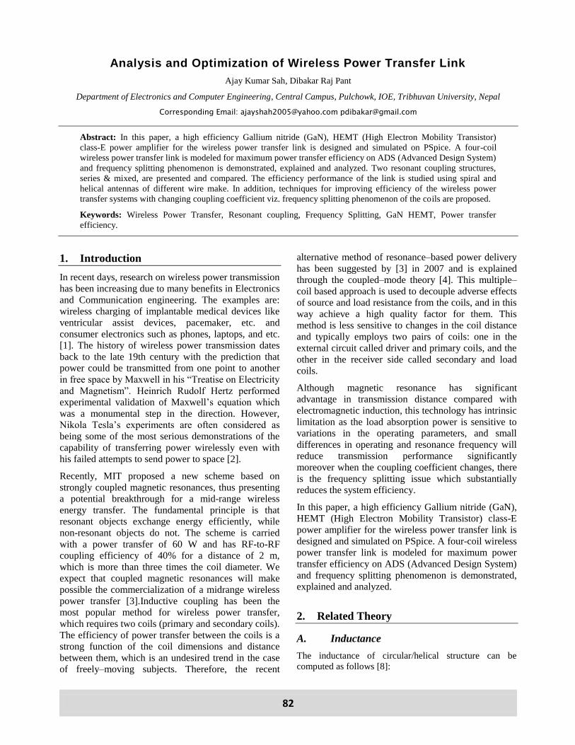
A. Inductance
The inductance of circular/helical structure can be
computed as follows [8]:
Proceedings of IOE Graduate Conference, 2014 83
Figure 1: Inductance Definition
Where:
N: Number of turns
: Relative permeability
R: Radius of the coil
: Radius of the cross section of the coil
Inductance is one of the characteristic variables of
conductor coils. The inductance of a conductor coil
depends totally upon the material properties
(permeability) of the space that the flux flows
through and the geometry of the layout.
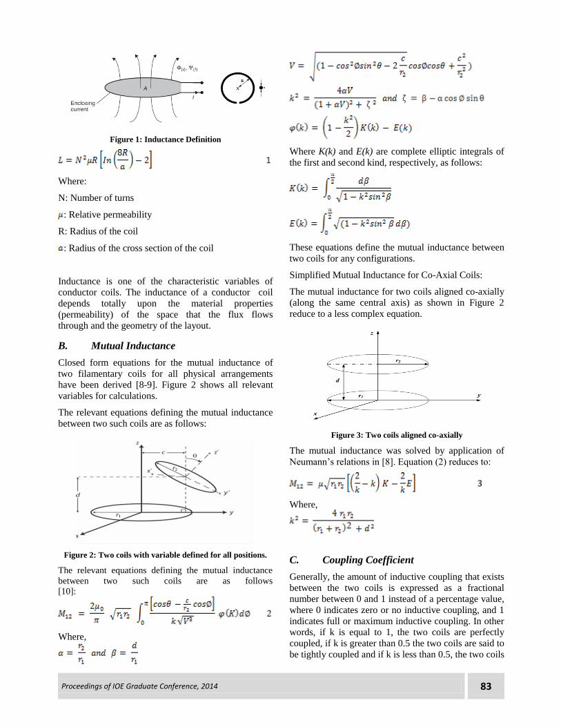
B. Mutual Inductance
Closed form equations for the mutual inductance of
two filamentary coils for all physical arrangements
have been derived [8-9]. Figure 2 shows all relevant
variables for calculations.
The relevant equations defining the mutual inductance
between two such coils are as follows:
Figure 2: Two coils with variable defined for all positions.
The relevant equations defining the mutual inductance
between two such coils are as follows
[10]:
Where,
Where K(k) and E(k) are complete elliptic integrals of
the first and second kind, respectively, as follows:
These equations define the mutual inductance between
two coils for any configurations.
Simplified Mutual Inductance for Co-Axial Coils:
The mutual inductance for two coils aligned co-axially
(along the same central axis) as shown in Figure 2
reduce to a less complex equation.
Figure 3: Two coils aligned co-axially
The mutual inductance was solved by application of
Neumann’s relations in [8]. Equation (2) reduces to:
Where,
C. Coupling Coefficient
Generally, the amount of inductive coupling that exists
between the two coils is expressed as a fractional
number between 0 and 1 instead of a percentage value,
where 0 indicates zero or no inductive coupling, and 1
indicates full or maximum inductive coupling. In other words, if k is equal to 1, the two coils are perfectly
coupled, if k is greater than 0.5 the two coils are said to
be tightly coupled and if k is less than 0.5, the two coils
84 Analysis and Optimization of Wireless Power Transfer Link
are said to be loosely coupled. Then the equation of
mutual inductance which assumes a perfect coupling
can be modified to take into account this coefficient of
coupling, k and is given as
When the coefficient of coupling, k is equal to 1, such
that all the lines of flux of on coil cut all of the turns of
the other, the mutual inductance is equal to the
geometric mean of the two individual inductances of
the coils. So, when the two inductances are equal and
L1 is equal to L2, the mutual inductance that exists
between the two coils can be defined as
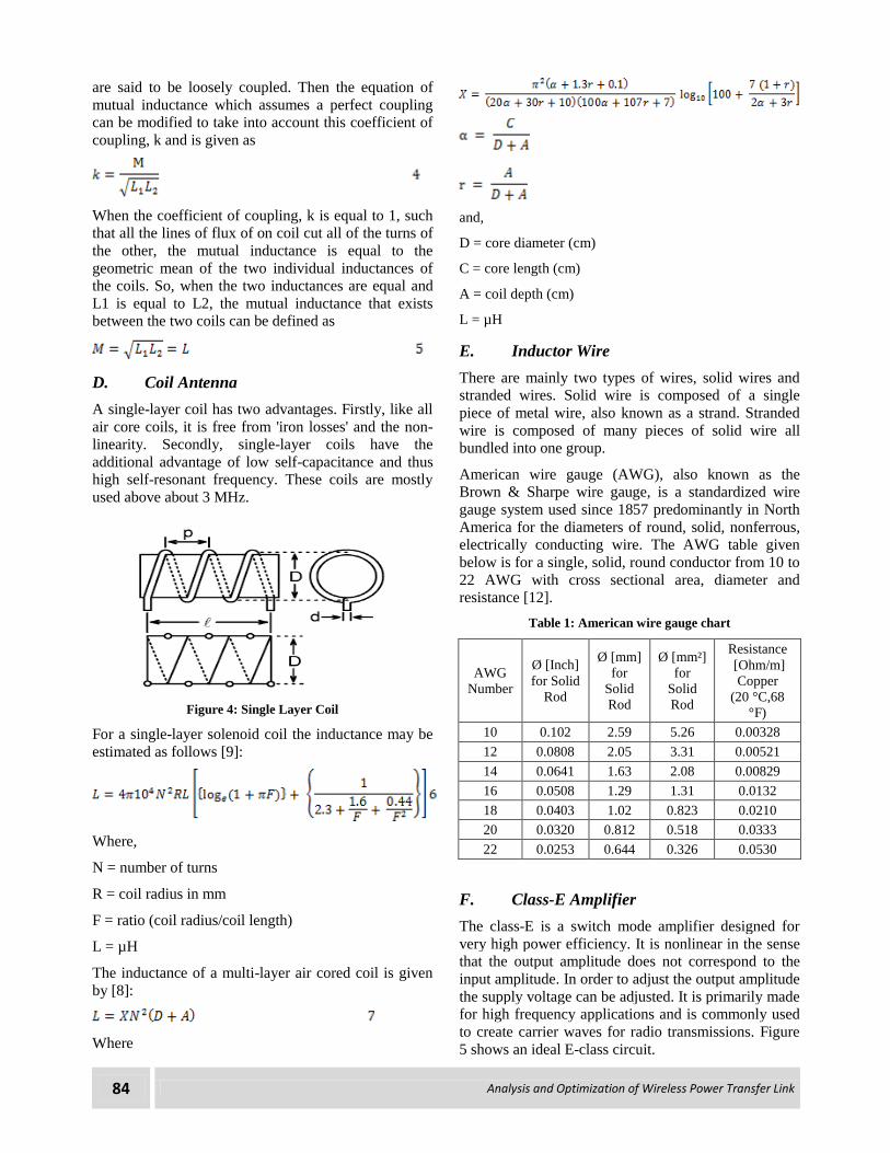
D. Coil Antenna
A single-layer coil has two advantages. Firstly, like all
air core coils, it is free from 'iron losses' and the non-
linearity. Secondly, single-layer coils have the
additional advantage of low self-capacitance and thus
high self-resonant frequency. These coils are mostly
used above about 3 MHz.
Figure 4: Single Layer Coil
For a single-layer solenoid coil the inductance may be
estimated as follows [9]:
Where,
N = number of turns
R = coil radius in mm
F = ratio (coil radius/coil length)
L = µH
The inductance of a multi-layer air cored coil is given
by [8]:
Where
and,
D = core diameter (cm)
C = core length (cm)
A = coil depth (cm)
L = µH
E. Inductor Wire
There are mainly two types of wires, solid wires and
stranded wires. Solid wire is composed of a single
piece of metal wire, also known as a strand. Stranded
wire is composed of many pieces of solid wire all
bundled into one group.
American wire gauge (AWG), also known as the
Brown & Sharpe wire gauge, is a standardized wire
gauge system used since 1857 predominantly in North
America for the diameters of round, solid, nonferrous,
electrically conducting wire. The AWG table given
below is for a single, solid, round conductor from 10 to
22 AWG with cross sectional area, diameter and
resistance [12].
Table 1: American wire gauge chart
AWG
Number
Ø [Inch]
for Solid
Rod
Ø [mm]
for
Solid
Rod
Ø [mm²]
for
Solid
Rod
Resistance
[Ohm/m]
Copper
(20 °C,68
°F)
10 0.102 2.59 5.26 0.00328
12 0.0808 2.05 3.31 0.00521
14 0.0641 1.63 2.08 0.00829
16 0.0508 1.29 1.31 0.0132
18 0.0403 1.02 0.823 0.0210
20 0.0320 0.812 0.518 0.0333
22 0.0253 0.644 0.326 0.0530
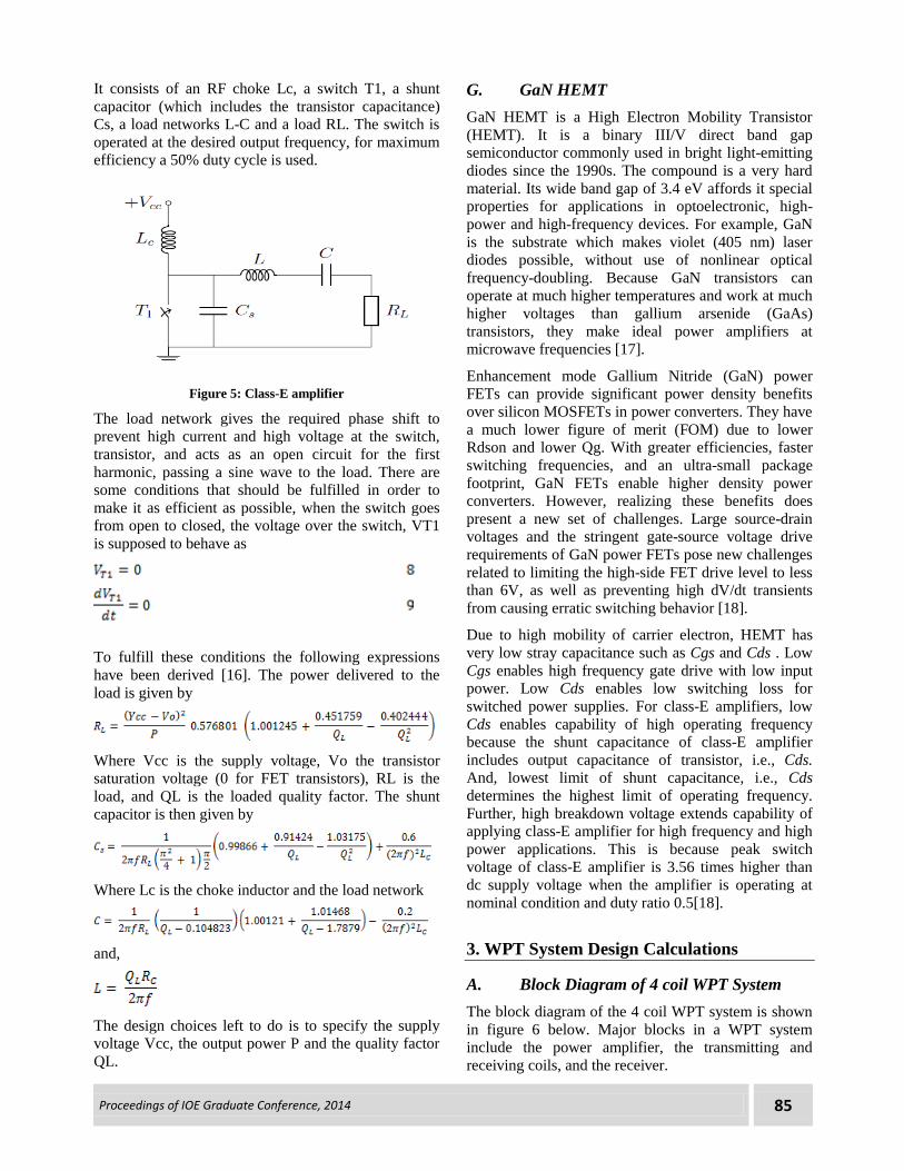
F. Class-E Amplifier
The class-E is a switch mode amplifier designed for
very high power efficiency. It is nonlinear in the sense
that the output amplitude does not correspond to the
input amplitude. In order to adjust the output amplitude
the supply voltage can be adjusted. It is primarily made for high frequency applications and is commonly used
to create carrier waves for radio transmissions. Figure
5 shows an ideal E-class circuit.
Proceedings of IOE Graduate Conference, 2014 85
It consists of an RF choke Lc, a switch T1, a shunt
capacitor (which includes the transistor capacitance)
Cs, a load networks L-C and a load RL. The switch is
operated at the desired output frequency, for maximum
efficiency a 50% duty cycle is used.
Figure 5: Class-E amplifier
The load network gives the required phase shift to
prevent high current and high voltage at the switch,
transistor, and acts as an open circuit for the first
harmonic, passing a sine wave to the load. There are
some conditions that should be fulfilled in order to
make it as efficient as possible, when the switch goes
from open to closed, the voltage over the switch, VT1
is supposed to behave as
To fulfill these conditions the following expressions
have been derived [16]. The power delivered to the
load is given by
Where Vcc is the supply voltage, Vo the transistor
saturation voltage (0 for FET transistors), RL is the
load, and QL is the loaded quality factor. The shunt
capacitor is then given by
Where Lc is the choke inductor and the load network
and,
The design choices left to do is to specify the supply
voltage Vcc, the output power P and the quality factor
QL.
G. GaN HEMT
GaN HEMT is a High Electron Mobility Transistor
(HEMT). It is a binary III/V direct band gap
semiconductor commonly used in bright light-emitting
diodes since the 1990s. The compound is a very hard
material. Its wide band gap of 3.4 eV affords it special
properties for applications in optoelectronic, high-
power and high-frequency devices. For example, GaN
is the substrate which makes violet (405 nm) laser
diodes possible, without use of nonlinear optical
frequency-doubling. Because GaN transistors can
operate at much higher temperatures and work at much
higher voltages than gallium arsenide (GaAs)
transistors, they make ideal power amplifiers at
microwave frequencies [17].
Enhancement mode Gallium Nitride (GaN) power
FETs can provide significant power density benefits
over silicon MOSFETs in power converters. They have
a much lower figure of merit (FOM) due to lower
Rdson and lower Qg. With greater efficiencies, faster
switching frequencies, and an ultra-small package
footprint, GaN FETs enable higher density power
converters. However, realizing these benefits does
present a new set of challenges. Large source-drain
voltages and the stringent gate-source voltage drive
requirements of GaN power FETs pose new challenges
related to limiting the high-side FET drive level to less
than 6V, as well as preventing high dV/dt transients
from causing erratic switching behavior [18].
Due to high mobility of carrier electron, HEMT has
very low stray capacitance such as Cgs and Cds . Low
Cgs enables high frequency gate drive with low input
power. Low Cds enables low switching loss for
switched power supplies. For class-E amplifiers, low
Cds enables capability of high operating frequency
because the shunt capacitance of class-E amplifier
includes output capacitance of transistor, i.e., Cds. And, lowest limit of shunt capacitance, i.e., Cds
determines the highest limit of operating frequency.
Further, high breakdown voltage extends capability of
applying class-E amplifier for high frequency and high
power applications. This is because peak switch
voltage of class-E amplifier is 3.56 times higher than
dc supply voltage when the amplifier is operating at
nominal condition and duty ratio 0.5[18].
3. WPT System Design Calculations
A. Block Diagram of 4 coil WPT System
The block diagram of the 4 coil WPT system is shown
in figure 6 below. Major blocks in a WPT system
include the power amplifier, the transmitting and
receiving coils, and the receiver.
86 Analysis and Optimization of Wireless Power Transfer Link
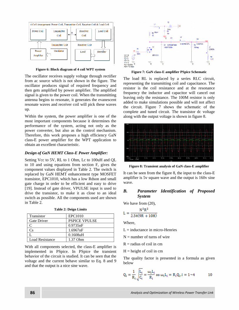
Figure 6: Block diagram of 4 coil WPT system
The oscillator receives supply voltage through rectifier
from ac source which is not shown in the figure. The
oscillator produces signal of required frequency and
then gets amplified by power amplifier. The amplified
signal is given to the power coil. When the transmitting
antenna begins to resonate, it generates the evanescent
resonate waves and receiver coil will pick these waves
up.
Within the system, the power amplifier is one of the
most important components because it determines the
performance of the system, acting not only as the
power converter, but also as the control mechanism.
Therefore, this work proposes a high efficiency GaN
class-E power amplifier for the WPT application to
obtain an excellent characteristic.
Design of GaN HEMT Class-E Power Amplifier:
Setting Vcc to 5V, RL to 1 Ohm, Lc to 100uH and QL
to 10 and using equations from section F, gives the
component values displayed in Table 2. The switch is
replaced by GaN HEMT enhancement type MOSFET
transistor, EPC1010, which has a low Rdson and small
gate charge in order to be efficient and easy to drive
[19]. Instead of gate driver, VPULSE input is used to
drive the transistor, to make it as close to an ideal
switch as possible. All the components used are shown
in Table 2.
Table 2: Deign Limits
Transistor EPC1010
Gate Driver PSPICE VPULSE
C 0.9735nF
Cs 1.6967nF
L 0.1608uH
Load Resistance 1.37 Ohm
With all components selected, the class-E amplifier is
implemented in PSpice. In PSpice the transient
behavior of the circuit is studied. It can be seen that the
voltage and the current behave similar to Eq. 8 and 9
and that the output is a nice sine wave.
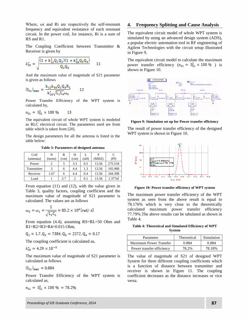
Figure 7: GaN class-E amplifier PSpice Schematic
The load RL is replaced by a series RLC circuit,
representing the transmitting coil and capacitance. The
resistor is the coil resistance and at the resonance
frequency the inductor and capacitor will cancel out
leaving only the resistance. The 100M resistor is only
added to make simulations possible and will not affect
the circuit. Figure 7 shows the schematic of the
complete and tuned circuit. The transistor dc voltage
along with the output voltage is shown in figure 8.
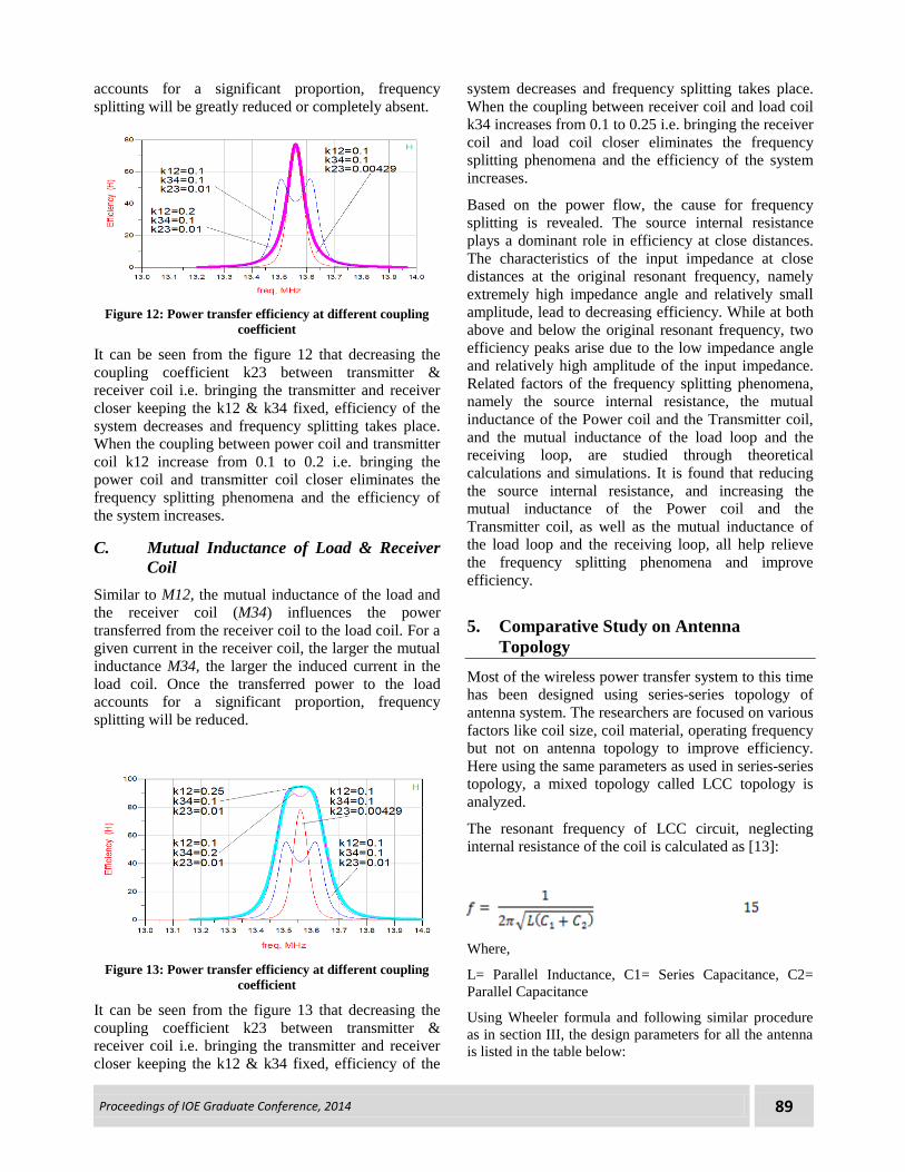
Figure 8: Transient analysis of GaN class-E amplifier
It can be seen from the figure 8, the input to the class-E
amplifier is 5v square wave and the output is 160v sine
wave.
B. Parameter Identification of Proposed
System
We have from (20),
Where,
L = inductance in micro-Henries
N = number of turns of wire
R = radius of coil in cm
H = height of coil in cm
The quality factor is presented in a formula as given
below
Proceedings of IOE Graduate Conference, 2014 87
Where, ωi and Ri are respectively the self-resonant
frequency and equivalent resistance of each resonant
circuit. In the power coil, for instance, Ri is a sum of
RS and R1.
The Coupling Coefficient between Transmitter &
Receiver is given by
And the maximum value of magnitude of S21 parameter
is given as follows
Power Transfer Efficiency of the WPT system is
calculated by,
The equivalent circuit of whole WPT system is modeled
as RLC electrical circuit. The parameters used are from
table which is taken from [20].
The design parameters for all the antenna is listed in the
table below:
Table 3: Parameters of designed antenna
Coil
(antenna)
N
(turns)
R
(cm)
H
(cm)
L
(uH)
F
(MHZ)
C
(Pf)
Power 2 5 3.3 0.5 13.56 275.518
Transmitter 3 6 4.4 1.3 13.56 105.968
Receiver 1.67 6 4.4 0.4 13.56 344.398
Load 1 3.7 2 0.1 13.56 1.377nf
From equation (11) and (12), with the value given in
Table 3, quality factors, coupling coefficient and the
maximum value of magnitude of S21 parameter is
calculated. The values are as follows
From equation (4.4), assuming RS=RL=50 Ohm and
R1=R2=R3=R4=0.015 Ohm,
The coupling coefficient is calculated as,
The maximum value of magnitude of S21 parameter is
calculated as follows
Power Transfer Efficiency of the WPT system is
calculated as,
4. Frequency Splitting and Cause Analysis
The equivalent circuit model of whole WPT system is
simulated by using an advanced design system (ADS),
a popular electric automation tool in RF engineering of
Agilent Technologies with the circuit setup illustrated
in Figure 9.
The equivalent circuit model to calculate the maximum
power transfer efficiency ( ) is
shown in Figure 10.
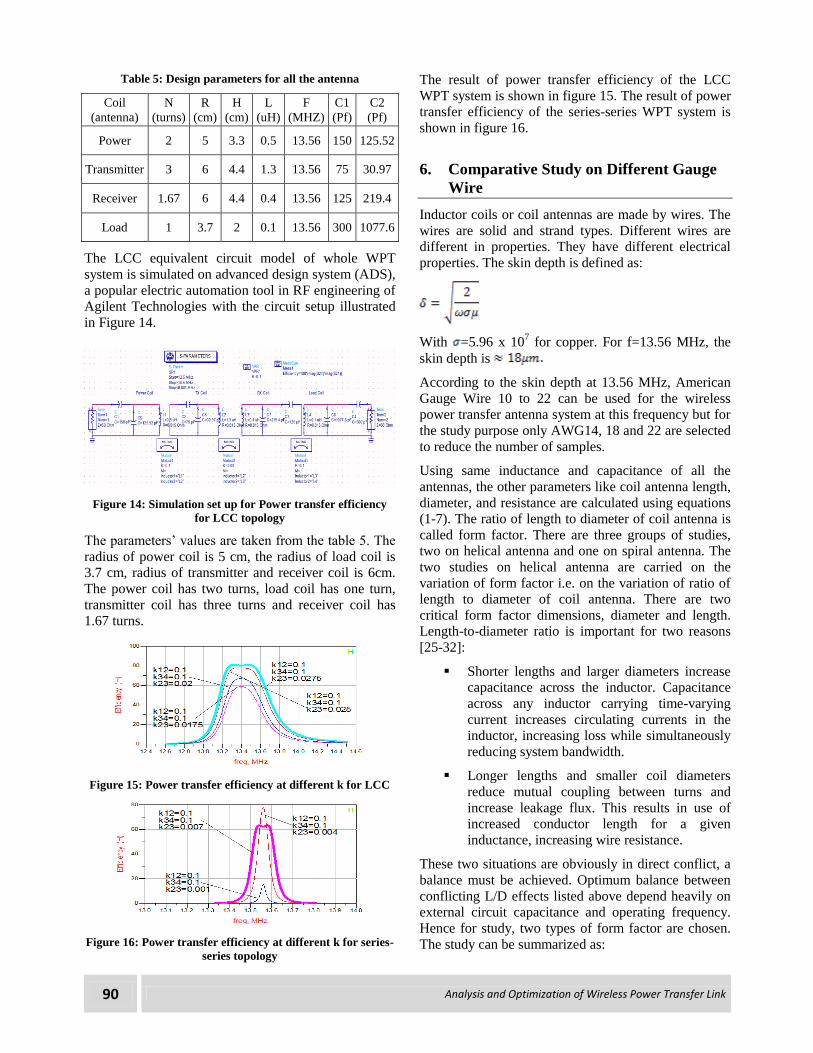
Figure 9: Simulation set up for Power transfer efficiency
The result of power transfer efficiency of the designed
WPT system is shown in Figure 10.
Figure 10: Power transfer efficiency of WPT system
The maximum power transfer efficiency of the WPT
system as seen from the above result is equal to
78.176% which is very close to the theoretically
calculated maximum power transfer efficiency
77.79%.The above results can be tabulated as shown in
Table 4.
Table 4: Theoretical and Simulated Efficiency of WPT
System
Parameter Theoretical Simulation
Maximum Power Transfer 0.884 0.884
Power transfer efficiency 78.2% 78.18%
The value of magnitude of S21 of designed WPT
System for three different coupling coefficients which
is a function of distance between transmitter and
receiver is shown in Figure 11. The coupling
coefficient decreases as the distance increases or vice versa.

88 Analysis and Optimization of Wireless Power Transfer Link
Figure 11: Simulation result showing │S21│ at different k23
Figure 11 reveals how efficiency varies with frequency
at different distances. At remote distances, the
efficiency peaks only at the resonant frequency. Closer
distance leads to frequency splitting. The efficiency
peaks at both below and above the original resonant
frequency. The shorter the transfer distance, more
obvious the phenomena is.
Efficiency reflects the distribution of the input power
in the viewpoint of power flow. The input power is
consumed in three aspects, i.e. the loss of the source
internal resistance, the ohmic losses of the resonant
coils, and the load. High efficiency is achieved when
the bulk of the input power is consumed in the load.
Any increase in the share of the ohmic losses of the
source internal resistance and the resonant coils leads
to lowered efficiency. As a consequence, analyzing the
effects of the source internal resistance and the
equivalent resistances of the resonant coils is of great
importance to frequency splitting. The expression of
the input impedance is deduced to examine how the
input impedance responds to the distance (namely
M23). At the resonant frequency, the input impedance
can be expressed as [21-24]:
14
Owing to the fact that the reduced distance leads to the
dramatic increase of the mutual inductance M23, the
amplitude of the input impedance is declining and the
angle is reaching towards 90°, close to pure
inductiveness. At close distances, the input impedance
is characteristic of large impedance angle and low
amplitude. The real part of the input impedance is
proportional to the power transferred and consumed from the source to the source loop, and the imaginary
part is in proportion to the power exchanged between
the source and the source loop. On the one hand, the
amplitude of the input impedance at close distances is
small enough to produce a large current in the source
loop, thus leading to a large source internal resistance
loss. On the other hand, due to the extremely large
impedance angle, the transferred power only accounts
for a small proportion of the large input power in the
source loop. Much power is exchanged between the
source and the source loop, without being transferred
to the load. Therefore, efficiency drops sharply.
In conclusion, the explanation for frequency splitting is
provided as follows. Close distances lead to the great
influence of the source internal resistance on
efficiency. At close distances, the input impedance at
the original resonant frequency point is characteristic
of extremely large impedance angle and relatively low
amplitude. Large impedance angle causes very low
transferred power, and much is exchanged between the
source and the source loop. Small amplitude results in
a large source current, thus increasing the source
internal resistance loss. Both of these two factors
reduce efficiency. While at below and above the
original resonant frequency, the input impedance is
characteristic of extremely small impedance angle and
relatively high amplitude. Due to the opposite
characteristics, efficiency peaks at these two frequency
points.
Frequency splitting occurs when the input impedance
is changed into small amplitude and large impedance
angle at close distances. In this section, the related
factors, i.e. the source internal resistance (Rs), the
mutual inductance between the Power coil and the
Transmitter coil (M12), and the mutual inductance
between the load loop and the receiving loop
(M34)[24], will be explored to pursue investigation
into their impacts on frequency splitting.
A. Source Internal Resistance
On the basis of the analysis above, it can be expected
that an increase of the source internal resistance will
highlight the frequency splitting phenomena.
Moreover, with a large enough increase in the source
internal resistance, frequency splitting will also appear
on the occasions where frequency splitting does not
occur previously.
B. Mutual Inductance of Source &
Transmitter Coil
The mutual inductance of the Power coil and the
Transmitter coil (M12) affects the amount of power
transferred from the Power coil to the Transmitter coil.
For a given current in the power coil, the larger the
mutual inductance M12, the larger the induced current
in the Transmitter coil. Once the transferred power
Proceedings of IOE Graduate Conference, 2014 89
accounts for a significant proportion, frequency
splitting will be greatly reduced or completely absent.
Figure 12: Power transfer efficiency at different coupling
coefficient
It can be seen from the figure 12 that decreasing the
coupling coefficient k23 between transmitter &
receiver coil i.e. bringing the transmitter and receiver
closer keeping the k12 & k34 fixed, efficiency of the
system decreases and frequency splitting takes place.
When the coupling between power coil and transmitter
coil k12 increase from 0.1 to 0.2 i.e. bringing the
power coil and transmitter coil closer eliminates the
frequency splitting phenomena and the efficiency of
the system increases.
C. Mutual Inductance of Load & Receiver
Coil
Similar to M12, the mutual inductance of the load and
the receiver coil (M34) influences the power
transferred from the receiver coil to the load coil. For a
given current in the receiver coil, the larger the mutual
inductance M34, the larger the induced current in the
load coil. Once the transferred power to the load
accounts for a significant proportion, frequency
splitting will be reduced.
Figure 13: Power transfer efficiency at different coupling
coefficient
It can be seen from the figure 13 that decreasing the
coupling coefficient k23 between transmitter &
receiver coil i.e. bringing the transmitter and receiver
closer keeping the k12 & k34 fixed, efficiency of the
system decreases and frequency splitting takes place.
When the coupling between receiver coil and load coil
k34 increases from 0.1 to 0.25 i.e. bringing the receiver
coil and load coil closer eliminates the frequency
splitting phenomena and the efficiency of the system
increases.
Based on the power flow, the cause for frequency
splitting is revealed. The source internal resistance
plays a dominant role in efficiency at close distances.
The characteristics of the input impedance at close
distances at the original resonant frequency, namely
extremely high impedance angle and relatively small
amplitude, lead to decreasing efficiency. While at both
above and below the original resonant frequency, two
efficiency peaks arise due to the low impedance angle
and relatively high amplitude of the input impedance.
Related factors of the frequency splitting phenomena,
namely the source internal resistance, the mutual
inductance of the Power coil and the Transmitter coil,
and the mutual inductance of the load loop and the
receiving loop, are studied through theoretical
calculations and simulations. It is found that reducing
the source internal resistance, and increasing the
mutual inductance of the Power coil and the
Transmitter coil, as well as the mutual inductance of
the load loop and the receiving loop, all help relieve
the frequency splitting phenomena and improve
efficiency.
5. Comparative Study on Antenna
Topology
Most of the wireless power transfer system to this time
has been designed using series-series topology of
antenna system. The researchers are focused on various
factors like coil size, coil material, operating frequency
but not on antenna topology to improve efficiency.
Here using the same parameters as used in series-series
topology, a mixed topology called LCC topology is
analyzed.
The resonant frequency of LCC circuit, neglecting
internal resistance of the coil is calculated as [13]:
Where,
L= Parallel Inductance, C1= Series Capacitance, C2=
Parallel Capacitance
Using Wheeler formula and following similar procedure
as in section III, the design parameters for all the antenna
is listed in the table below:
90 Analysis and Optimization of Wireless Power Transfer Link
Table 5: Design parameters for all the antenna
Coil
(antenna)
N
(turns)
R
(cm)
H
(cm)
L
(uH)
F
(MHZ)
C1
(Pf)
C2
(Pf)
Power 2 5 3.3 0.5 13.56 150 125.52
Transmitter 3 6 4.4 1.3 13.56 75 30.97
Receiver 1.67 6 4.4 0.4 13.56 125 219.4
Load 1 3.7 2 0.1 13.56 300 1077.6
The LCC equivalent circuit model of whole WPT
system is simulated on advanced design system (ADS),
a popular electric automation tool in RF engineering of
Agilent Technologies with the circuit setup illustrated
in Figure 14.
Figure 14: Simulation set up for Power transfer efficiency
for LCC topology
The parameters’ values are taken from the table 5. The
radius of power coil is 5 cm, the radius of load coil is
3.7 cm, radius of transmitter and receiver coil is 6cm.
The power coil has two turns, load coil has one turn,
transmitter coil has three turns and receiver coil has
1.67 turns.
Figure 15: Power transfer efficiency at different k for LCC
Figure 16: Power transfer efficiency at different k for series-
series topology
The result of power transfer efficiency of the LCC
WPT system is shown in figure 15. The result of power
transfer efficiency of the series-series WPT system is
shown in figure 16.
6. Comparative Study on Different Gauge
Wire
Inductor coils or coil antennas are made by wires. The
wires are solid and strand types. Different wires are
different in properties. They have different electrical
properties. The skin depth is defined as:
With =5.96 x 10⁷ for copper. For f=13.56 MHz, the
skin depth is
According to the skin depth at 13.56 MHz, American
Gauge Wire 10 to 22 can be used for the wireless
power transfer antenna system at this frequency but for
the study purpose only AWG14, 18 and 22 are selected
to reduce the number of samples.
Using same inductance and capacitance of all the
antennas, the other parameters like coil antenna length,
diameter, and resistance are calculated using equations
(1-7). The ratio of length to diameter of coil antenna is
called form factor. There are three groups of studies,
two on helical antenna and one on spiral antenna. The
two studies on helical antenna are carried on the
variation of form factor i.e. on the variation of ratio of
length to diameter of coil antenna. There are two
critical form factor dimensions, diameter and length.
Length-to-diameter ratio is important for two reasons
[25-32]:
Shorter lengths and larger diameters increase
capacitance across the inductor. Capacitance
across any inductor carrying time-varying
current increases circulating currents in the
inductor, increasing loss while simultaneously
reducing system bandwidth.
Longer lengths and smaller coil diameters
reduce mutual coupling between turns and
increase leakage flux. This results in use of
increased conductor length for a given
inductance, increasing wire resistance.
These two situations are obviously in direct conflict, a
balance must be achieved. Optimum balance between
conflicting L/D effects listed above depend heavily on
external circuit capacitance and operating frequency.
Hence for study, two types of form factor are chosen.
The study can be summarized as:
Proceedings of IOE Graduate Conference, 2014 91
1. Helical antenna 1 (0.5≤ Form Factor ≥0.6)
2. Helical antenna 2 (1≤ Form Factor ≥1.65)
3. Spiral Antenna
The parameters of helical antenna 1, helical antenna 2
are calculated using single-layer air coil equation (6).
The parameters of spiral antenna are calculated using
multi-layer air coil equation (7). The resistances are
calculated using calcoil software. When length of the
multilayer coil is kept equal to diameter of wire and
increasing the single turn per layer, a spiral antenna is
forms.
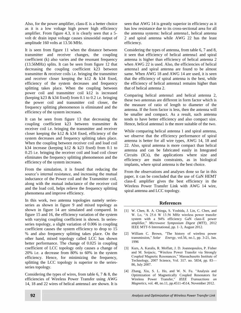
The maximum efficiencies for AWG 18 and AWG 14
wire are calculated using equations (11-13). The
simulation result of maximum efficiency of wireless
power transfer link using AWG 14, 18 and 22 wire for
helical antenna is shown in figure 17.
Figure 17: Power transfer efficiency of different wire gauge
The maximum efficiencies for AWG 18 and AWG 14
wire are calculated. The simulation result of maximum
efficiency of wireless power transfer link using AWG
14, 18 and 22 wire for helical antenna is shown in
figure 18.
Figure 18: Power transfer efficiency of different wire gauge
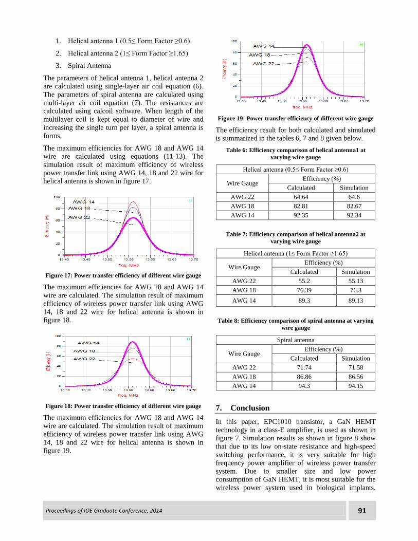
The maximum efficiencies for AWG 18 and AWG 14
wire are calculated. The simulation result of maximum
efficiency of wireless power transfer link using AWG
14, 18 and 22 wire for helical antenna is shown in
figure 19.
Figure 19: Power transfer efficiency of different wire gauge
The efficiency result for both calculated and simulated
is summarized in the tables 6, 7 and 8 given below.
Table 6: Efficiency comparison of helical antenna1 at
varying wire gauge
Helical antenna (0.5≤ Form Factor ≥0.6)
Wire Gauge Efficiency (%)
Calculated Simulation
AWG 22 64.64 64.6
AWG 18 82.81 82.67
AWG 14 92.35 92.34
Table 7: Efficiency comparison of helical antenna2 at
varying wire gauge
Helical antenna (1≤ Form Factor ≥1.65)
Wire Gauge Efficiency (%)
Calculated Simulation
AWG 22 55.2 55.13
AWG 18 76.39 76.3
AWG 14 89.3 89.13
Table 8: Efficiency comparison of spiral antenna at varying
wire gauge
Spiral antenna
Wire Gauge Efficiency (%)
Calculated Simulation
AWG 22 71.74 71.58
AWG 18 86.86 86.56
AWG 14 94.3 94.15
7. Conclusion
In this paper, EPC1010 transistor, a GaN HEMT
technology in a class-E amplifier, is used as shown in
figure 7. Simulation results as shown in figure 8 show
that due to its low on-state resistance and high-speed
switching performance, it is very suitable for high
frequency power amplifier of wireless power transfer
system. Due to smaller size and low power
consumption of GaN HEMT, it is most suitable for the
wireless power system used in biological implants.
92 Analysis and Optimization of Wireless Power Transfer Link
Also, for the power amplifier, class-E is a better choice
as it is a low voltage high power high efficiency
amplifier. From figure 4.3, it is clearly seen that a 5-
volt dc drain input voltage causes sinusoidal output of
amplitude 160 volts at 13.56 MHz.
It is seen from figure 11 when the distance between
transmitter and receiver changes, the coupling
coefficient (k) also varies and the resonant frequency
(13.56MHz) splits. It can be seen from figure 12 that
decreasing the coupling coefficient k23 between
transmitter & receiver coils i.e. bringing the transmitter
and receiver closer keeping the k12 & k34 fixed,
efficiency of the system decreases and frequency
splitting takes place. When the coupling between
power coil and transmitter coil k12 is increased
(keeping k23 & k34 fixed) from 0.1 to 0.2 i.e. bringing
the power coil and transmitter coil closer, the
frequency splitting phenomenon is eliminated and the
efficiency of the system increases.
It can be seen from figure 13 that decreasing the
coupling coefficient k23 between transmitter &
receiver coil i.e. bringing the transmitter and receiver
closer keeping the k12 & k34 fixed, efficiency of the
system decreases and frequency splitting takes place.
When the coupling between receiver coil and load coil
k34 increase (keeping k12 & k23 fixed) from 0.1 to
0.25 i.e. bringing the receiver coil and load coil closer
eliminates the frequency splitting phenomenon and the
efficiency of the system increases.
From the simulation, it is found that reducing the
source’s internal resistance, and increasing the mutual
inductance of the Power coil and the Transmitter coil,
along with the mutual inductance of the receiver coil
and the load coil, helps relieve the frequency splitting
phenomena and improve efficiency.
In this work, two antenna topologies namely series-
series as shown in figure 9 and mixed topology as
shown in figure 14 are simulated and compared. In
figure 15 and 16, the efficiency variation of the system
with varying coupling coefficient is shown. In series-
series topology, a slight variation of 0.006 in coupling
coefficient causes the system efficiency to drop to 15
% and also frequency splitting takes place. On the
other hand, mixed topology called LCC has shown
better performance. The change of 0.025 in coupling
coefficient of LCC topology only causes a change of
20% i.e. a decrease from 80% to 60% in the system
efficiency. Hence, for minimizing the frequency,
splitting the LCC topology is superior to the series-
series topology.
Considering the types of wires, from table 6, 7 & 8, the
efficiencies of Wireless Power Transfer using AWG
14, 18 and 22 wires of helical antenna1 are shown. It is
seen that AWG 14 is greatly superior in efficiency as it
has low resistance due to its cross-sectional area for all
the antenna systems: helical antenna1, helical antenna
2 and spiral antenna while AWG 22 has the least
efficiency.
Considering the types of antenna, from table 6, 7 and 8,
it seen that efficiency of helical antenna1 and spiral
antenna is higher than efficiency of helical antenna 2
when AWG 22 is used. Also, the efficiencies of helical
antenna1 and spiral antenna are found to be almost
same. When AWG 18 and AWG 14 are used, it is seen
that the efficiency of spiral antenna is the best, while
the efficiency of helical antenna1 remains higher than
that of helical antenna 2.
Comparing helical antenna1 and helical antenna 2,
these two antennas are different in form factor which is
the measure of ratio of length to diameter of the
antenna. If the form factor is less, then the antenna will
be smaller and compact. As a result, such antenna
tends to have better efficiency and also compact size.
Hence, helical antenna1 is the more suitable of the two.
While comparing helical antenna 1 and spiral antenna,
we observe that the efficiency performance of spiral
antenna is better for all wire types, AWG 14, 18 and
22. Also, spiral antenna is more compact than helical
antenna and can be fabricated easily in Integrated
Circuits (ICs), the applications where size and
efficiency are main constraints, as in biological
implants, where spiral antenna is the best choice.
From the observations and analyses done so far in this
paper, it can be concluded that the use of GaN HEMT
class-E amplifier gives the best efficiency in the
Wireless Power Transfer Link with AWG 14 wire,
spiral antenna and LCC topology.
References
[1] W. Chen, R. A. Chinga, S. Yoshida, J. Lin, C. Chen, and
W. Lo, “A 25.6 W 13.56 MHz wireless power transfer
system with a 94% efficiency GaN class-E power
amplifier,” Microwave Symposium Digest (MTT), 2012
IEEE MTT-S International, pp. 1–3, August 2012.
[2] William C. Brown, "The history of wireless power
transmission," Solar Energy, vol.56, no.1, pp. 3-21, Jan.
1996
[3] Kurs, A. Karalis, R. Moffatt, J. D. Joannopoulos, P. Fisher
and M. Soijacic, “Wireless Power Transfer via Strongly
Coupled Magnetic Resonances,” Massachusetts Institute of
Technology, 2007 Science, Vol. 317. no. 5834, pp. 83—
86, July 2007.
[4] Zhang, Xiu, S. L. Ho, and W. N. Fu. "Analysis and
Optimization of Magnetically Coupled Resonators for
Wireless Power Transfer," IEEE Transactions on
Magnetics, vol. 48, no.11, pp.4511-4514, November 2012.

Proceedings of IOE Graduate Conference, 2014 93
[5] Chen, Linhui, Shuo Liu, Yong Chun Zhou, and Tie Jun
Cui, "An optimizable circuit structure for high-efficiency
wireless power transfer," IEEE Transactions on Industrial
Electronics, vol. 60, no. 1, pp.339-349, January 2013.
[6] Nadakuduti, Jagadish, Lin Lu, and Paul Guckian,
"Operating frequency selection for loosely coupled wireless
power transfer systems with respect to RF emissions and
RF exposure requirements," In Wireless Power Transfer
(WPT), 2013 IEEE, pp. 234-237. IEEE, May 2013.
[7] Karalis, Aristeidis, John D. Joannopoulos, and Marin
Soljačić. "Efficient wireless non-radiative mid-range
energy transfer." Annals of Physics 323.1, pp. 34-48,
January 2008
[8] Babic, Slobodan I., Frederic Sirois, and Cevdet Akyel.
"Validity check of mutual inductance formulas for circular
filaments with lateral and angular
misalignments." Progress In Electromagnetics Research M,
vol. 8, pp. 15-26, 2009
[9] Grover, Frederick W. "The calculation of the mutual
inductance of circular filaments in any desired
positions." Proceedings of the IRE 32.10, pp. 620-629,
1944
[10] Lundin, Richard. "A handbook formula for the inductance
of a single-layer circular coil." Proceedings of the
IEEE 73.9, pp. 1428-9, 1985
[11] Grover, Frederick W. Inductance calculations: working
formulas and tables. Courier Dover Publications, 2004.
[12] http://en.wikipedia.org/wiki/American_wire_gauge
[13] Nilsson, James William., and Susan A. Riedel. Electric
Circuits. Boston: Prentice Hall, 2011. Print
[14] Kawamura, Atsuo, and Tae-Woong Kim. "Proposed
Equivalent Circuit and Parameter Identification Method for
Electro-Magnetic Resonance Based Wireless Power
Transfer.” April 2013
[15] Beh, TeckChuan, et al. "Wireless Power Transfer System
via Magnetic Resonant Coupling at Fixed Resonance
Frequency―Power Transfer System Based on Impedance
Matching―." Proc. The 25th World Battery, Hybrid and
Fuel Cell Electric Vehicle Symposium & Exhibition
(EVS25). November 2010.
[16] Sokal, Nathan O. "Class-E RF power amplifiers." QEX
Commun. Quart 204, pp. 9-20, 2001
[17] de Rooij, Michael A., and Johan T. Strydom. "eGaN FETs
in Low Power Wireless Energy Converters." ECS
Transactions 50.3, pp. 377-388, 2013
[18] Uchiyama, Hiroyuki, et al. "Consideration of impact of
GaN HEMT for class E amplifier." TENCON 2010-2010
IEEE Region 10 Conference. IEEE, 2010.
[19] http://epc-co.com/epc/documents/datasheets/
EPC1010_datasheet.pdf
[20] Sah, Ajay Kumar and Timalsina, Arun. “Design of Simple
Wireless Power Transfer System via Magnetic Resonant
Coupling at 13.56MHz.” Proceedings of IOE Graduate
Conference, Vol. 1, pp. 206-210, November 2013
[21] Yang, Ching-Wen, and Chin-Lung Yang. "Analysis on
numbers and adaptive ranges of resonators for efficient
resonant coupling wireless power transmission." Wireless
Power Transfer Conference (WPTC), 2014 IEEE. IEEE,
2014.
[22] Zhang, Y., Zhengming Zhao, and Kainan Chen.
"Frequency Splitting Analysis of Four-Coil Resonant
Wireless Power Transfer.", Energy Conversion Congress
and Exposition (ECCE), 2013 IEEE , pp. 1-1, September
2013
[23] Yiming Zhang, Zhengming Zhao and Kainan Chen,
"Frequency splitting analysis of magnetically-coupled
resonant wireless power transfer," Energy Conversion
Congress and Exposition (ECCE), 2013 IEEE , pp.2227-
2232, 15-19 September 2013.
[24] Y. Zhang, Z. Zhao and K. Chen, "Frequency decrease
analysis of resonant wireless power transfer," IEEE Trans.
Power Electron., vol. 29, no. 3, pp. 1058-1063, Mar. 2014.
[25] Waters, Benjamin H., et al. "Optimal coil size ratios for
wireless power transfer applications." Circuits and Systems
(ISCAS), 2014 IEEE International Symposium on. IEEE,
2014.
[26] Yan, Zhuo, et al. "Influence Factors Analysis and
Improvement Method on Efficiency of Wireless Power
Transfer Via Coupled Magnetic Resonance."Magnetics,
IEEE Transactions on 50.4, pp. 1-4, 2014
[27] Choi, Hyo-Jin, Sangbin Lee, and Cheolung Cha.
"Optimization of geometric parameters for circular loop
antenna in magnetic coupled wireless power
transfer." Wireless Power Transfer Conference (WPTC),
2014 IEEE. IEEE, 2014.
[28] Sample, Alanson P., David A. Meyer, and Joshua R. Smith.
"Analysis, experimental results, and range adaptation of
magnetically coupled resonators for wireless power
transfer," IEEE Transactions on Industrial Electronics, vol.
58, no. 2, pp. 544-554, February 2011.
[29] Hwang, Hyeonseok, et al. "An analysis of magnetic
resonance coupling effects on wireless power transfer by
coil inductance and placement." Consumer Electronics,
IEEE Transactions on 60.2, pp. 203-209, 2014
[30] Fu, Minfan, et al. "Subsystem-level efficiency analysis of a
wireless power transfer system." Wireless Power Transfer
Conference (WPTC), 2014 IEEE. IEEE, 2014.
[31] Zhang, Yiming, Zhengming Zhao, and Ting Lu.
"Quantitative Analysis of System Efficiency and Output
Power of Four-Coil Resonant Wireless Power Transfer."
IEEE Transactions on Power Electronics, pp. 1-1, 2013.
[32] Pozar, David M. Microwave engineering. John Wiley &
Sons, 2009.
[33] Jordan, Edward C., and K. G. Balmain. Electromagnetic
Waves and Radiating Systems. Second ed. New Dehli:
Prentice-Hall of India, 2006. Print.
[34] Jonah, Olutola, "Optimization of Wireless Power Transfer
via Magnetic Resonance in Different Media," Ph.D. Thesis,
FIU Electronic Theses and Dissertations, Paper 876, March
2013.