analysis and redesign of spokes on rotary kiln · 2.2 thermal load given the rotary kiln is heated...
TRANSCRIPT

THE 5th STUDENT SYMPOSIUM ON MECHANICAL AND MANUFACTURING ENGINEERING
ANALYSIS AND REDESIGN OF SPOKES ON ROTARY KILN
Adrien Chereau, Fahimeh Shakibapour, Ioakeim Dourlios, Karim A. Moaty and Yang-Che Lin
Department of Mechanical and Manufacturing Engineering, Aalborg UniversityFibigerstraede 16, DK-9220 Aalborg East, Denmark
Email: achere17, fshaki16, idourl16, kmoaty16, [email protected],Web page: http://www.mechman.m-tech.aau.dk/
AbstractIn asphalt mixing plants, the rotary kiln is a massive machine whose function is to dry and heat a mixture of sand andgravel. The rotation of the kiln is transferred through supporting rings which are fitted to the drum shell by meansof spokes. Loads acting on these spokes are both thermal and mechanical. Indeed, the rotary kiln is highly heatedby a burner and loaded as well by its self-weight and the raw material passing through it. The spokes are weldedonto both the supporting ring and the drum shell. Fatigue can lead after some time of operation to spoke or weldcrack. In this article, a load investigation is carried out using analytical and numerical approaches. Stress results areobtained by finite element simulation and numerical model is compared with strain gauge measurements performedon an operating rotary kiln. Then, fatigue analysis is conducted to find the expected lifetime of both the spoke andthe welds. Finally, an optimized redesign of the spoke is presented to improve fatigue lifetime.
Keywords: Rotary kiln, Fatigue, Finite Element Analysis, Welded joints, Optimization, Redesign
1. Introduction
Rotary kilns are extensively used for asphalt, cementand in other industries because of their efficient mixingperformance and heat transfer capacity [1]. In asphaltproduction, their function is to provide a first mix andraise raw material, composed of sand and aggregates, toa high temperature. Raw material is fed into the rotarykiln from one end and a burner supplies heat at the otherend, as shown in Fig.1.
Fig. 1 Elements of rotary kiln studied
The studied rotary kiln employs two ring-roller stations,each with eighteen welded spokes, to transmit torquefrom rotating rollers to the drum shell. During operation,spokes are cyclically loaded by the self-weight of thestructure as well as the raw material passing by. In worstcase scenarios both loads combined can reach more than30 tons. In addition, the temperature of the drum shell at
the burner end can reach around 400◦ C creating a largegradient of temperature throughout the rotary kiln. Thetemperature difference imposes a significant additionalload on the spokes.
Fatigue is a main concern here since crack formationsare noticed on both spokes and welds. On the cold sideof the kiln (i.e. far away from the burner), cracks appearon the spoke (see Fig.2), whereas they initiate on thewelds on the hot side (i.e. close to the burner). Thesefailures require maintenance and repairing procedureswhich are costly as well as time-consuming.
Fig. 2 Spoke and crack propagation on the cold side
This paper focuses on detailed analysis and redesign ofthe kiln spokes on the cold side. Firstly, a load modelis built considering both mechanical and thermal loads.Numerical analysis is then carried out to extract stressresults for fatigue analysis. To verify the simulationmodel, strain gauge measurements are performed onan operating rotary kiln. Finally, an improved lifetimespoke is designed using optimization methods.
1

2. Load model
To approximate the load acting on the rotary kiln in asteady-state, a static model is taken into consideration.Consequently, dynamic effects as torsion on spokes atstart or cascading bed motion are neglected. The loadsacting on the 10-meter long kiln can be categorizedas the self-weight of the kiln (15 tons), the rawmaterial (16 tons) and the thermal load due to theburner. All components are made of structural steel.The drum is assumed parallel with the ground and otherspecifications are given in Tab.I.
Reaction force of the rollers F 151 kNOuter drum shell radius R1 1235 mmInner ring radius R′1 1320 mmOuter ring radius R2 1415 mmAngle of rollers wrt. vertical axis 37 ◦
Rotating speed of the kiln 8 rpm
Tab. I Specifications of rotary kiln studied
An analytical model is built to study the influence ofmechanical load. Besides that, the thermal load is takeninto account in the numerical model.
2.1 Mechanical Load
Based on research presented in [2], a two-dimensional(2D) static analysis is performed to obtain bending stressdistribution on the ring (spokes are omitted here). Inorder to model the reality more accurately, the rawmaterial inside the rotary kiln is considered to beunevenly distributed (i.e. bed motion) as shown in Fig.3.
qdqm
Qb Qa
!
0∘
270∘
100∘
200∘
90∘
217∘ 143∘
Y
X
Rotating direction M0 N0
Fig. 3 Two-dimension model with uneven load distribution
The distributed loads qd and qm represent the self-weight of kiln and raw material, respectively. Qa and Qbare the reaction forces contributed by the two supportingrollers. M0 is the bending moment and N0 is thehorizontal force acting on the cross section. Both qd andqm are assumed to be functions of cosine and can beexpressed as Eq.1. The resultant forces of qd and qm aredenoted as Qd and Qm, respectively. The coefficientsin Eq.1 are determined by assuming (a) the summationof Qd and Qm in X-direction is equal to F and (b)Qd = Qm due to the fact that the weight of the kilnand raw material are almost the same.
qd =0.3412 · F
R1· cos (ϕ)
qm =0.5188 · F
R1· cos
(9
5ϕ− π
2
) (1)
In order to find bending stress distribution on the ring,moment must be considered first. The ring can be treatedas a curved beam. The bending moment Mb acting onthe ring can be found by Eq.2, where Mqd and Mqm
are the moment caused by qd and qm, respectively andRavg = (R1 +R2) /2.
Mb = M0 +N0Ravg (1− cosϕ) +Mqd +Mqm
−QaRavg sin
(ϕ− 5π
6
)−QbRavg sin
(ϕ− 7π
6
)(2)
By applying Castigliano theorem, M0 and N0 can bedetermined as shown in Eq.3. α|ϕ=0 is the rotationangle and δ|ϕ=0 is the horizontal displacement at ϕ = 0.Note that since the material is not evenly distributed,they are not exactly zero but have negligible values.
α|ϕ=0 =∂U
∂M0
∣∣∣∣ϕ=0
=RavgEI
∫ π
0
2Mb ·∂Mb
∂M0dϕ = 0
δ|ϕ=0 =∂U
∂N0
∣∣∣∣ϕ=0
=RavgEI
∫ π
0
2Mb ·∂Mb
∂N0dϕ = 0
(3)
Finally, the bending stress σb on the inner surface ofthe ring (i.e. on the drum shell) can be found by Eq.4[2], where A is the area of the ring cross sectionand Rn = (R2 −R1) / ln (R2/R1). The distribution ispresented in Fig.4.
σb =Mb (Rn −R1)
AR1 (Ravg −Rn)(4)
2

0 90 180 270 360Degree
-1.5
-1
-0.5
0
0.5
1
1.5
2
2.5
Stre
ss (P
a)
107 Bending stress on inner surface of the ring
Fig. 4 Bending stress on the inner surface of the ring
Instead of one single ring, the rotary kiln studied in thisarticle has a set of spokes between the drum and thering. Therefore, this analytical model is not directly usedbut it provides an understanding of stress distribution onthe drum shell. Futhermore, distributed loads qd and qmare reutilized in the numerical model.
2.2 Thermal Load
Given the rotary kiln is heated by a burner, componentsare subjected to thermal expansion which impliesthermal stresses, especially on the spokes. This occursbecause the shell and the ring do not have the sametemperature creating a significant temperature differenceon the spoke, even on the cold side. The spokes arewelded onto both the shell and the ring and thereforetheir expansion are restricted at both ends which resultsin thermal stresses.
In order to obtain thermal stresses on the spokes, analy-sis is done in the numerical model which is elaborated insection 3.2. However, a general understanding of the ba-sic principles of heat transfer and the coefficients neededfor the Finite Element Analysis (FEA) are discussedfirst. Basically, there are three modes of heat transfer:conduction, convection and radiation which require todefine temperature distribution, heat transfer coefficientand emissivity, respectively [3].
Heat transfer coefficient for spokes is found in tablesfrom reference [3]. To obtain temperature field andemissivity of the spokes, an experiment is taken intoconsideration using an infrared (IR) camera. In an IRthermography application, object’s surface emissivity iscrucial since it significantly impacts the temperaturemeasurement results. Different methods exist in order toobtain it [4]. The method applied in this case is by usingthermometer working parallel to the camera, spoke’s
emissivity has been measured to 0,93. Afterwards, thetemperature distribution for spokes on the cold side ofthe rotary kiln is captured and is shown in Fig.5.
Fig. 5 Temperature distribution for spokes captured by IRcamera (◦C)
3. Finite Element Analysis
FEA is considered here because it is hard to predictboundary conditions of the spokes analytically. Inaddition, it is convenient to extract results for fatigueanalysis of the spokes and the welds as well asperforming shape optimization. A three-dimensional(3D) model of the rotary kiln is therefore studiedusing ANSYS Workbench with the actual boundaryconditions. Accurate results on local areas can beobtained using submodeling procedure from the roughmodel.
3.1 Submodeling
The full 3D geometry of the rotary kiln is modeled fordifferent reasons. The first one is because only loadsacting on the entire structure are known. The otherreason is that no symmetric simplification can be donebecause of the unevenly distributed load (bed motion)and the position of the kiln with respect to the rollers.As shown in Fig.6 (a), only relevant parts are includedin this model.
In this study, multiple submodels are introduced for dif-ferent purposes as it can be seen in Fig.6. Submodelingis a finite element technique which enables to zoom intoa region of interest, to refine the mesh and to get moreaccurate results.
(a) (b) (c)
(d)
(e)
Fig. 6 Submodeling process
3

Firstly, the full model of the rotary kiln (a) is solvedwith a coarse mesh. Then, a submodel (b) is consideredto compare strains with the strain gauge measurements,to locate the critical position of the spokes and to extractresults for fatigue analysis. Once the critical position isdetermined, a new submodel (c) is made to be used tofind a better design of spoke using shape optimization.Finally, two submodels (d) and (e) are placed on eachweld of the spoke considered in order to apply the notchstress method for fatigue assessment of welded joints.
3.2 Mesh and Boundary Conditions
Once the modeling part is done, the structure should bediscretized that is to say divided into a series of simpleelements defined by n nodes [5]. For static analysis,higher order 3D SOLID186 elements are used.
Defining the most suitable boundary conditions iscrucial in FEA, even more for thermo-mechanicalanalysis where both thermal and structural boundaryconditions have to be determined. Rollers are consideredas cylindrical fixed supports. Their contact with thering is defined as No Seperation contact due to itsability to allow some small sliding. It is assumed thatthe displacements are small compared to the length ofthe rotary kiln.
The thermal load should be applied according to thedata mentioned in section 2.2. This means that thesame temperature distribution and emissivity capturedby the IR camera are used in the model. Moreover, heattransfer coefficient is considered for the spokes due tothe convection (see Fig.7).
Fig. 7 Boundary conditions for the thermal analysis per-formed on submodel (b)
By importing the nodal temperatures from the steady-state thermal analysis into the static structural scheme,thermal stresses are computed. By adding static loads aspressure acting on the drum shell, boundary conditionsare completed.
3.3 Numerical Results
After solving the FEA submodel Fig.6 (b), stress resultscan be extracted and evaluated. As seen in Fig.8, themaximum principal stress (σ1) is noticed highest on thespoke at the identified reference point. The maximumprincipal stress remains highest at the reference pointthroughout one revolution of the kiln.
Fig. 8 Maximum principal stresses at the critical position ofthe spoke
Recalling Fig.2, it can be said that the FEA model isvalidated by the existence of the crack at the samelocation as in the reference point. In order to evaluatethis effect of this high stress on the lifetime, a fatigueanalysis is essential to be carried out. To do so, acyclic load is extracted using the submodel presented inFig.9 to obtain the maximum principal stresses from thesame reference point for eighteen spokes. This illustratesthe stress variation through one revolution. Noted thatsmall additional rotations are done in order to have asatisfactory overview of the stress range. Results arerepresented in Tab.II with the same numeration as inFig.9.
Fig. 9 Submodel with critical region where σ1 is maximum
4

Also, it can be seen in Tab.II that a critical region existsbetween the two rollers as predicted in section 2.1.
Spoke Max. Principal Stress Spoke Max. Principal Stress1 103.21 MPa 10 49.76MPa2 10.49 MPa 11 37.38 MPa3 4.62 MPa 12 33.93 MPa4 11.19 MPa 13 35.43 MPa5 41.06 MPa 14 56.57 MPa6 42.09 MPa 15 39.21 MPa7 33.9 MPa 16 5.31 MPa8 15.97 MPa 17 87.81 MPa9 52.81 MPa 18 97.01 MPa
Tab. II Maximum principal stresses obtained from thespokes (see Fig.9) at the reference point (see Fig.8)
4. Wireless Strain Gauge Experiment
To verify if the assumptions taken for the numericalmodel built in FEA are correct, strain gauge experimenton an operating rotary kiln in an asphalt plant is done.To perform such an experiment, a wireless strain gaugesetup is used which consists of different componentsincluding a strain gauge (input sensor), a wirelessnode (transmitter), a gateway (receiver) and a specificsoftware to save the data [6].
In the experiment conducted for this article, one singlestrain gauge is attached on a spoke on the cold side ofthe rotary kiln. After the setup and the calibration done,the rotary kiln starts operating. Then data is recordedonce the rotary kiln has reached a steady-state condition.It means that the raw material is introduced within thekiln rotating with a constant speed of 8 rpm and thetemperature field is steady along its length.
Fig. 10 Strain gauge location on rotary kiln and CAD model
The location where the strain gauge is attached duringthe experiment is as well considered in the numericalmodel (see Fig.10). Afterwards, normal strains areextracted from the eighteen FEA spokes. For onerevolution of the rotary kiln, both strain results are
plotted in Fig.11. The shape of these two curves seemssimilar and cohesive.
Fig. 11 Experimental and numerical results on eighteenspokes for one revolution of the rotary kiln
The maximum peak for the strain gauge is located in thearea where the bed motion ends. The other maximumis situated between the two rollers. Also, two strainminima are observed when the spoke passes throughthe rollers.
For the strain gauge measurements, it can be explainedthat one peak is higher than the other by the fact thatin reality the temperature field is not evenly distributedalong the cross section. In fact, the bed motion whichis unevenly distributed conducts heat implying someadditional thermal load at its location.
It is worth mentioning that the values from the numer-ical model are shrinked by a factor of three in Fig.11.Two main explanations have been formulated about theoverestimation of the FEA model compared to the straingauge measurements:- Either one software parameter called Slope, deter-mined automatically after strain gauge calibration, is notreliable and gives lower strain gauge results. To extractstrains from the data collected by the software, Eq.5must be used [7].
Output = Slope ∗Bits+Offset (5)
Using a slope three times higher, the results for bothstrain gauge measurements and the numerical modelwould be comparable.- Or the contacts assumed in FEA are too conservative.
5

5. Fatigue Analysis
The definition of fatigue is the process of progressivelocalized permanent structural change occurring in amaterial subjected to conditions that produce fluctuatingstresses and strains at some points which may culminatein cracks or complete fracture after a sufficient numberof fluctuations [8]. As mentioned before, fatigue plays amajor role in the failure of both the spoke and the welds.It is therefore vital to introduce fatigue assessmentapproaches to evaluate the lifetime of the spoke andthe welds based on the analysis conducted in section 3.
5.1 Fatigue of Welded Joints
There are different fatigue strength assessment ap-proaches that can be used to evaluate the fatigue lifetimeof welded joints. In this work, the notch stress approachis used for this evaluation process since it is found tobe the most suitable. This is in regard to the size andcomplexity of the components of the rotary kiln, and italso fits best with the current FEA models. The approachis very flexible in the sense that both the toe and theroot of all types of welded joints can be assessed usinga single S-N curve [9].
Fig. 12 Schematic principles of fatigue assessment using thenotch stress approach [9]
The basic work flow of this approach is illustrated inFig.12. The notch stress approach correlates the stressrange in a fictitious rounding in the weld toe or rootto the fatigue life using a single S-N curve. The notchstress is typically calculated using finite element models,which is also suggested from the IIW recommendations[10], with a reference radius of 1mm (the notch)to avoid the presence of stress singularities in sharpnotches. A very fine mesh is needed so that the localstresses can converge. It is indicated by Fricke [11]that quadratic elements should be used with maximumelement length of 0.25mm in the case of a 1mm notchradius. In this paper, the notch stresses are calculatedusing the largest numerical principal stress range andassessed against a S-N curve, commonly the fatigueclass of FAT225 as indicated by Sonsino [12].
As mentioned before, a fine meshed region is needed to-wards the notch area to get accurate stresses. Therefore,
the submodeling technique is applied as seen in Fig.6.The principal stresses are then extracted accordingly aspresented in Tab.III.
Position σ1 σ2 σ3
Ring 70 MPa -55 MPa 1,35 MPaShell 18 MPa -133 MPa -12 MPa
Tab. III Principal Stresses on welds at ring and shell
Based on the values in Tab.III, the largest numericalprincipal stress range for both welds located on thering and the shell, as seen in figure 6, are computed.The calculation procedure is formulated in Eq.6. It isworth mentioning that the stress range is conservativelycalculated to obtain a maximum value. Note that σref ,which is the value of principal stress when the rotarykiln is not loaded, is set to 0.
Ring: ∆σR = σ1 − σref = 70MPa
Shell: ∆σS = σref − σ2 = 133MPa(6)
Fig. 13 S-N curve of fatigue class in terms of the notch stress(FAT225) [11]
According to the fatigue curve of FAT225 and the valuesobtained as seen in Fig.13, the weld on the ring hasan infinite lifetime while the weld on the shell has anexpected lifetime of 6·107 which is considered too large.This conclusion is expected since investigation showsthat far away from the burner (i.e. cold side) only thespokes failed at the ring and not the welds. It is thereforereasonable to obtain such results for the fatigue lifetimeof the welds.
6

5.2 Fatigue Analysis of Spoke
Components and structures are continuously subjectedto quite diverse load histories. At one extreme, theirhistories may be rather simple and repetitive, also knownas the constant amplitude loading. At the other extreme,they may be completely random, also referred to asvariable amplitude loading in this case [8].
It is important to point out that the spokes studied aresubjected to a load that varies during operation, that is tosay a variable amplitude loading. In this case, a methodis needed in order to deal with such situation since thisvariable amplitude spectrum is not suitable for directuse of S-N curve.
Fig. 14 Variable amplitude loading model
To estimate the fatigue life of the spoke, the schematicshown in Fig.14 is followed accordingly. The procedurestarts by calculating the first principal stress, σ1, at acertain reference point from the FEA model as shownin Fig.8. At this location, the stresses are at a maximumthroughout the entire operation. This reference pointis the same location where actual cracks propagateand failure occurs at the spoke, as seen in Fig.2. Theextracted principal stresses are plotted in a time historygraph, as illustrated in Fig.15, where rainflow countingmethod can afterwards be applied.
Fig. 15 Load history diagram
Rainflow counting method is considered as one ofthe best methods for cycle counting [8]. This methodidentifies all of the stress ranges as well as indicatingall reversals. In the next step, the stress ranges ∆σi aregrouped in suitable intervals. The total number of cycles
ni in each interval corresponds to half the number ofreversals. The results from this procedure are shown inTab.IV.
∆σ[MPa] 2·ni ni ∆σi ni(∆σi)3
0-15 6 3 7.5 1265.625(*)15-35 7 3.5 25 54687.5(*)35-55 5 2.5 45 227812.5(*)55-75 4 2 65 549250(*)75-95 2 1 85 614125
95-115 2 1 105 1157627∑4 2 — 1771752
Tab. IV Procedure of rainflow counting
From Tab.IV, the concept of an equivalent stress rangeto correlate data from variable amplitude cyclic loadtests with data from constant amplitude tests can nowbe implemented. The concept states that, for the samenumber of cycles, the equivalent (constant amplitude)stress range will cause the same fatigue damage as thesequence of variable amplitude stress ranges it replaces[13]. The equivalent stress range can be expressed asEq.7.
∆σeq =
(∑(ni(∆σi
)m)∑ni
) 1m
(7)
Substituting the values in Tab.IV into Eq.7, the equiv-alent stress is therefore equal to ∆σeq = 96MPa. Itis now possible to read off the allowable equivalentnumber of cycle nf,eq as seen from Fig.16. The valueapproximately corresponds to nf,eq = 4 · 106. The S-Ncurve used is of detail category 125 from the Eurocodestandards [14] as it fits the specifications and descriptionof the spoke.
Fig. 16 Allowable equivalent number of cycles nf,eq [14]
7

The damage D caused by the equivalent stress range canbe calculated using Eq.8. It is stated that no damageoccurs if D ≤ 1. Also, the lifetime of the spoke isevaluated using Eq.9 where time corresponds to onerevolution of the rotary kiln and is equal to 7.5 s. Thetotal life is expected to be 4166h of operating time.
D =
∑ni
nf,eq(8)
tf =nf,eq∑ni· time = 4166h (9)
If it is assumed that the rotary kiln operates eight hoursper day, failure is then expected to occur on the spokeafter 520 days.
6. Optimization
The basic concept of optimization is to find a solutionwhich can minimize the objective (cost) function sub-jected to several equality and inequality constraints. Inorder to increase life time of the spokes, the objectivefunction is set to be the maximum principal stress. Tofind the optimum design, one approach with MATLABand the other one with ANSYS Workbench are consid-ered. Combining the results from two approaches, thenew design of spoke is presented and evaluated in theend.
6.1 Optimization in MATLAB
The optimization is carried out by MATLAB build-in optimizer "fmincon" with gradient based algorithmsequential quadratic programming (SQP) [15]. A batchfile of ANSYS APDL is created containing the in-formation of model geometry, design variables, mesh,boundary conditions and data outputs. This batch fileis used as a function to run evaluations and providesthe necessary information for further optimization. Themodel geometry, containing only one spoke without anywelding, is built using bottom-up modeling. Hence, itis possible to analyze the new model at each iterationwhen one point (i.e. design variable) is moved duringoptimization. It should be emphasized that the boundaryconditions are taken from the result of ANSYS Work-bench submodeling. Due to the lack of contact stressinformation in Workbench, the stresses are lower inAPDL. However, the contours of stress in both modelsare very similar. In conclusion, the optimization resultof this model is served as a first guess which should beevaluated carefully.
Additionally, multi-objective function is applied in theinterest of obtaining a better result. The procedure isdescribed as follows (a) sort the maximum principalstress values in a descending order (b) select the first 500values to be the objective functions fk, k is 1 to 500(c) treat the functions with Kreisselmeier-Steinhauser(KS) function (Eq.10) and set it to be the final objectivefunction. Note that ρ is taken as 4 in this case. fmax isthe largest value among the objective functions and nis the number of objective functions.
fKS = fmax +1
ρlog
(n∑k=1
eρ(fk−fmax)
)(10)
Fig.17 shows the design variables (DV) set up and thecomparison of original and optimized shape. There areeight points set on the boundary of the model withdifferent constraints. Note that the bound indicates thedesign variables can only move in horizontal direction.The maximum principal stress on the optimized spoke isreduced by 15% compare to the value of original spoke.
Fig. 17 Design variables set up and result in MATLAB
6.2 Optimization in ANSYS
Given the insufficiency of the MATLAB script to opti-mize main dimensions of the spoke, an other approachusing ANSYS Workbench is used. The built-in opti-mizer ANSYS DesignXplorer enables to solve optimiza-tion problems with different algorithms including the socalled Multi-Objective Genetic Algorithm (MOGA)[16].Genetic Algorithm (GA) is a meta-heuristic relying onbio-inspired operators such as mutation, crossover andnatural selection to generate a new population [17].This optimization method is therefore used to avoid thepossibility of trapping in a local minimum.
There are two objective functions considered in theproblem. The first one (high priority objective function)concerns maximum principal stress on a path of the
8
spoke, where the critical point is located. The secondone concerns maximum principal stress on the surfaceof the spoke in order to monitor any shift of the criticalpoint. Five parameters of the spoke are defined in thisoptimization problem as shown in Fig.18.
Critical Maximum Principal Stress
P4
P5P1
P2 P3
Fig. 18 Optimization parameters defined on the spoke
After eight numbers of MOGA iterations, the bestcandidate point is returned by DesignXplorer. It showsthat the maximum principal stress of the critical pointhas reduced from 121 MPa to 86.8 MPa, whichimplies a 28% reduction. The bounds and optimizedvalues of parameters are given in Tab.V. It can benoticed that after optimization all these parameters areclose to the lower bounds defined.
Parameters Lower bound Upper bound Optimized valueP1 (mm) 420 455 421,7P2 (mm) 85 105 86,3P3 (mm) 240 280 247,9P4 (mm) 350 420 353,3P5 (mm) 12 25 12,4
Tab. V Bounds and optimized values of input parameters
6.3 Results evaluation
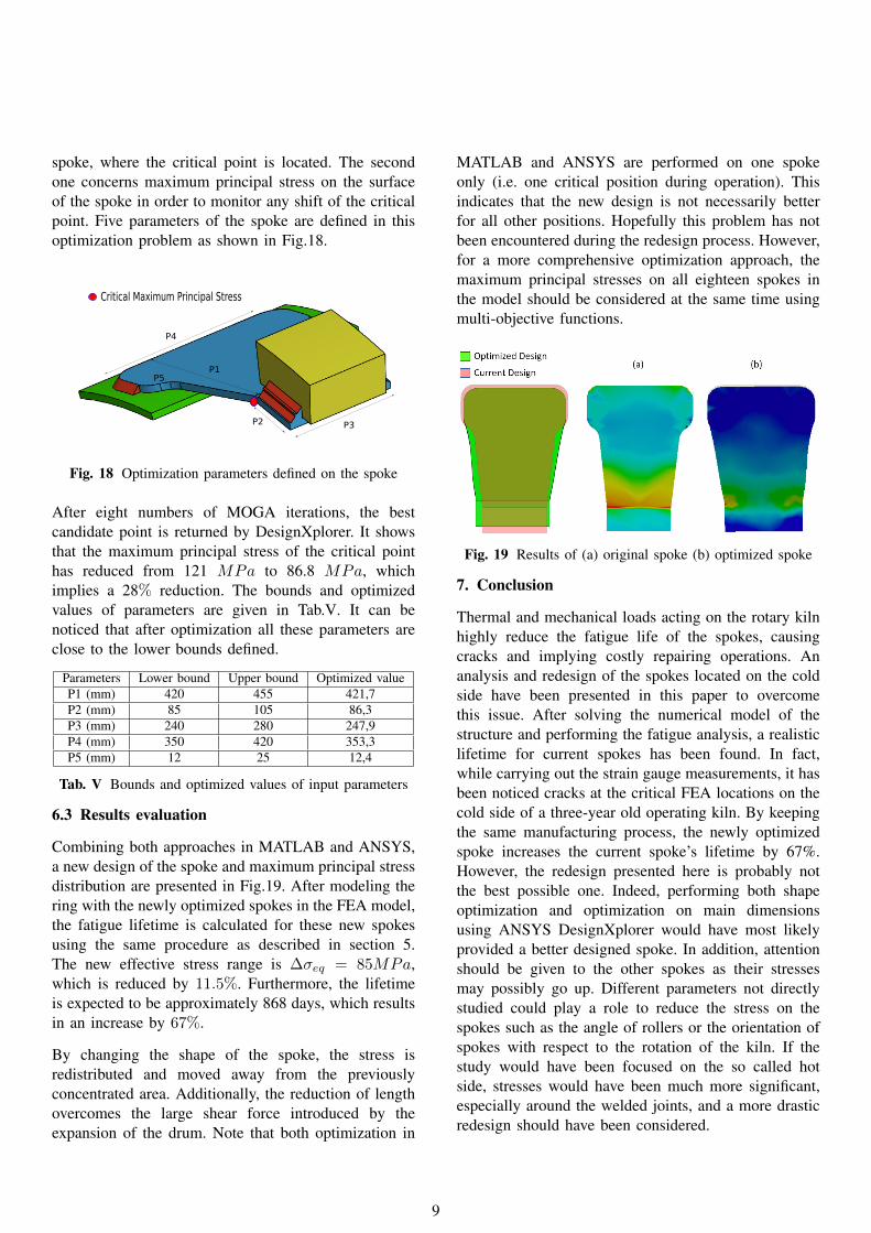
Combining both approaches in MATLAB and ANSYS,a new design of the spoke and maximum principal stressdistribution are presented in Fig.19. After modeling thering with the newly optimized spokes in the FEA model,the fatigue lifetime is calculated for these new spokesusing the same procedure as described in section 5.The new effective stress range is ∆σeq = 85MPa,which is reduced by 11.5%. Furthermore, the lifetimeis expected to be approximately 868 days, which resultsin an increase by 67%.
By changing the shape of the spoke, the stress isredistributed and moved away from the previouslyconcentrated area. Additionally, the reduction of lengthovercomes the large shear force introduced by theexpansion of the drum. Note that both optimization in
MATLAB and ANSYS are performed on one spokeonly (i.e. one critical position during operation). Thisindicates that the new design is not necessarily betterfor all other positions. Hopefully this problem has notbeen encountered during the redesign process. However,for a more comprehensive optimization approach, themaximum principal stresses on all eighteen spokes inthe model should be considered at the same time usingmulti-objective functions.
Fig. 19 Results of (a) original spoke (b) optimized spoke
7. Conclusion
Thermal and mechanical loads acting on the rotary kilnhighly reduce the fatigue life of the spokes, causingcracks and implying costly repairing operations. Ananalysis and redesign of the spokes located on the coldside have been presented in this paper to overcomethis issue. After solving the numerical model of thestructure and performing the fatigue analysis, a realisticlifetime for current spokes has been found. In fact,while carrying out the strain gauge measurements, it hasbeen noticed cracks at the critical FEA locations on thecold side of a three-year old operating kiln. By keepingthe same manufacturing process, the newly optimizedspoke increases the current spoke’s lifetime by 67%.However, the redesign presented here is probably notthe best possible one. Indeed, performing both shapeoptimization and optimization on main dimensionsusing ANSYS DesignXplorer would have most likelyprovided a better designed spoke. In addition, attentionshould be given to the other spokes as their stressesmay possibly go up. Different parameters not directlystudied could play a role to reduce the stress on thespokes such as the angle of rollers or the orientation ofspokes with respect to the rotation of the kiln. If thestudy would have been focused on the so called hotside, stresses would have been much more significant,especially around the welded joints, and a more drasticredesign should have been considered.
9

AcknowledgementThe authors of this work gratefully acknowledge Sintexfor sponsoring the 5th MechMan symposium.
References[1] A. A. Boateng, Rotary Kiln. Elsevier, 2008.[2] A. Z. et al, “Analytical and numerical stress
analysis of the rotary kiln ring,”[3] Y. A. Cengel, Heat Transfer. Mcgraw-Hill,
2nd ed., 2002.[4] “Keysight technologies how to measure the
unknown thermal emissivity of objects/materialsusing the u5855a trueir thermal imager,” 2015.
[5] Cook et al, Concepts and applications of finiteelement analysis. Wiley, 3rd ed., 2002.
[6] “Lord user manual, v-link-lxrs wireless 7 channelanalog input sensor nodel,” 2015.
[7] “User guide version 8500-0017 rev 001 little,wsda-base-101 analog output base stationl,” 2011.
[8] Stephensl, Metal Fatigue in Engineering.Mcgraw-Hill, 2nd ed., 2000.
[9] O. s. H. M. R. A. J. G. Pedersen, MikkelMelters; Mouritsen, “Experience with the notchstress approach for fatigue assessment of weldedjoints,” 2010.
[10] A. Hobbacher, Recommendations for FatigueDesign of Welded Joints and Components.Springer, 2nd ed., 2014.
[11] W. Fricke, “Iiw recommendations for the fatigueassessment of welded structures by notchl,” 2010.
[12] C.M.Sonsino, “A consideration of allowableequivalent stresses for fatigue design of weldedjoints according to the notch stress concept withthe reference radii rref = 1.00 and 0.05 mm,”2009.
[13] J.M.Bloom, Probabilistic Fracture Mechanics andFatigue Methods. STP 798, 1st ed., 1983.
[14] “Eurocode 3,” 2007.[15] J. S. Arora, Introduction to Optimum Design.
4th ed., 2017.[16] “Design xploration user guide,” 2015.[17] A. S. A. Konak, D.W. Coit, “Multi-objective
optimiation using genetic algorithms: a tutorial,”Elsevier, pp. 993–995, 2005.
10