analysis, design, and testing of a low force … · linear proof mass actuator for structural...
TRANSCRIPT

ANALYSIS, DESIGN, AND TESTING OF A LOW COST, DIRECT FORCE COMMAND
LINEAR PROOF MASS ACTUATOR
FOR STRUCTURAL CONTROL
G.L. Slater
Professor
Department of Aerospace Engineering
and Engineering Mechanics
Stuart Shelley
Research Assistant Professor
Department of Mechanical, Industrial, and Nuclear
Engineering
University of Cincinnati
Mark Jacobson
Undergraduate student
Department of Mechanical Engineering
The Ohio State University
Abstract
In this paper, the design, analysis, and test of a low cost,
linear proof mass actuator for vibration control is presented. The
actuator is based on a linear induction coil from a large computer
disk drive. Such disk drives are readily available and provide the
linear actuator, current feedback amplifier, and power supply for
a highly effective, yet inexpensive, experimental laboratory
actuator. The device is implemented as a force command input
system, and the performance is virtually the same as other, more
sophisticated, linear proof mass systems.
Introduction
Vibration suppression for large flexible structures in space
requires some meansof transferring the mechanical vibration energy
into heat. A popularly proposed solution to implement this in
realizable hardware is the linear proof mass actuator (or "Linear
Momentum Exchange Device"). (see Refs. 1-3) The linear actuator
achieves control by accelerating a mass along a linear track. The
force driver is a linear motor, which applies a force to the moving
mass, and hence by Newton's Laws, an equal and opposite force
applied to the structure on which the actuator is mounted. If an
ideal "velocity sensor" is used to apply the driving signal to a
"perfect" force actuator, we have the classical force-velocity
collocated control scheme, which is guaranteed to be energy
dissipative, and results in a stable, damped structure.
751
https://ntrs.nasa.gov/search.jsp?R=19930009754 2018-07-05T07:10:14+00:00Z

The use of linear proof-mass actuators for control has long been
recognized as a useful technique for implementing this type of
control scheme. In addition to action as a control actuator, an
alternate application of this device is as a force producer, where
it acts essentially as a mechanical shaker. As a shaker, this
device is capable of exciting the structure through a force input
at the physical location of the mounting between the actuator andthe structure.
The construction of linear proof mass actuators is conceptually
quite simple, yet in practice, tends to be difficult to implement.
They are heavy, the desired friction free linear track motion is
difficult to maintain due to the precision alignment required for
the linear motion, stiction in the bearings, and magnetization of
the bearings and other materials. For laboratory experimentation,
the construction of such actuators may be an expensive, time
consuming task. The purpose of this paper is to report on an easy,
low-cost implementation of a proof mass actuator which may besuitable for laboratory studies.
Proof Mass Actuator Description
The key element being proposed here to construct a proof mass
actuator is to utilize the head actuation mechanism from a hard
disk drive. For this application it is relatively easy to find
obsolete disk drives, which are fairly large, heavy, and very
reliable. The mechanism in these older drives is a sophisticated
implementation of a common voice coil moving in a magnetic field.
The primary advantages of these actuators are: (i) They are fairly
large, hence they are easy to work with in a laboratory
environment, (2) the mechanisms are very precise and reliable. The
suspension system and track of the actuator are very smooth with
low friction, and(3)theprimaryelectroniccomponent in the actuators
is a high precision constant current DC amplifier. The constant
current feature eliminates the back emf effect seen in a constant
voltage drive system, hence there is almost no interaction of the
actuator dynamics with the structure on which it is mounted.
The proof mass actuators constructed in our laboratory wereconstructed from old Hewlett Packard HP7925D disk drives. These
are relatively old (circa 1980), fairly large drives which are
obsolete for use as data storage devices. Nevertheless, the
electronics and actuation are still perfectly good, and the head
positioning subsystem of the disk drive makes an excellent proof
mass actuator. This consists of a linear actuator, with
approximately a four inch stroke, plus the power supply and
regulator. For laboratory work this actuator produces several
advantages. First it is reasonably inexpensive! Surplus drives of
this type are commonly available for several hundred dollars. It
is likely that most organizations have drives of this or other similar
types, sitting around as unused, surplus equipment. Secondly, the
linear actuator is fairly large, making it relatively easy to work
on and modify. (Of course, it is also large and heavy making it
less than desirable for a realistic space actuator. For our
752
purposes, however, this is not viewed as a major problem.)
The mass moves within a coil of approximately three inches
in diameter. Current passing through the coil produces a magnetic
field, which produces a force on the mass moving within the coil.
The standard mass of the actuator moving within the coil is quite
small, especially in comparison to the fixed mass of the actuator.
Because there is ample room on the actuator, additional mass was
added to make the device more efficient in producing force without
being track limited. The primary limitation on the amount of mass
that can be added is the bearing which guides the actuator on its
track. For our design we rather arbitrarily used a nominal 2.2 kg
additional mass on the actuator to reduce the stroke required
especially at low frequencies.
The current driving the coil comes from a current amplifier
which produces a current proportional to the input voltage. The
specifications for the power supply and amplifier can be found inthe manufacturer's documentation but should be measured in situ to
get the correct value for your individual system. For the HP
drives used the manual specifies the amplifier gain as 1.2 amp/v.
Laboratory measurements obtained a value closer to 1 amp/v, with
some slight variations within the group of amplifiers tested. The
actuator itself was tested by constraining the actuator mass and
using a load cell to measure the force produced by the coil. For
the system tested the nominal value of this gain was found to be
between 1-2 ib/amp. This value can vary widely between systems and
is very sensitive to the track alignment in the system. The
nominal force constant in the system is close to the upper figure.
Disassembly of, or damage to, the permanent magnet during
construction can reduce the magnetic flux and reduce the force
constant toward the lower value. Nevertheless it is easy to see
from this value that the actuator can be very effective in
producing a force on the attaching structure.
Conversion to a Force Actuator
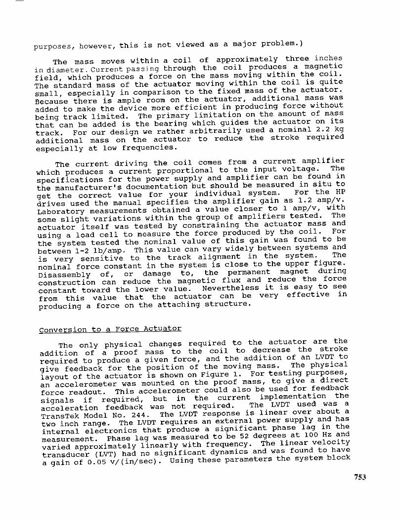
The only physical changes required to the actuator are the
addition of a proof mass to the coil to decrease the stroke
required to produce a given force, and the addition of an LVDT to
give feedback for the position of the moving mass. The physical
layout of the actuator is shown on Figure I. For testing purposes,
an accelerometer was mounted on the proof mass, to give a direct
force readout. This accelerometer could also be used for feedback
signals if required, but in the current implementation the
acceleration feedback was not required. The LVDT used was a
TransTek Model No. 244. The LVDT response is linear over about a
two inch range. The LVDT requires an external power supply and has
internal electronics that produce a significant phase lag in the
measurement. Phase lag was measured to be 52 degrees at i00 Hz and
varied approximately linearly with frequency. The linear velocity
transducer (LVT) had no significant dynamics and was found to have
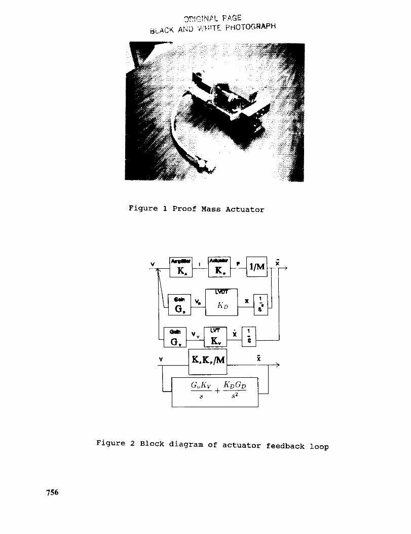
a gain of 0.05 v/(in/sec). Using these parameters the system block
753

diagram was modeled as shown in Figure 2. The overall transfer
function (neglecting the dynamics of the LVDT) are a second ordersystem
F KaK: 2
v ,2÷K x/C:+KoX/C ,
where K(.) indicates an appropriate gain witha - Amplifier
f- Force/current constant
V- LVT transducer gain
D- LVDT gain
A simple operational amplifier circuit was added to sum the LVT and
LVDT signals, and to allow relative scaling of the signals to theamplifier. The general schematic of this circuit is shown in
Figure 3. For our purposes the gains were set to give a low
frequency cutoff of about three Hertz. Initial tests showed a lot
of high frequency noise corrupting these feedback signals and
causing very poor performance. Shielding all the leads from the
sensors to the op-amps, and adding a number of small capacitors to
the circuitry as shown on the figure, ultimately eliminated this
problem and made the system respond very nicely.
Test results
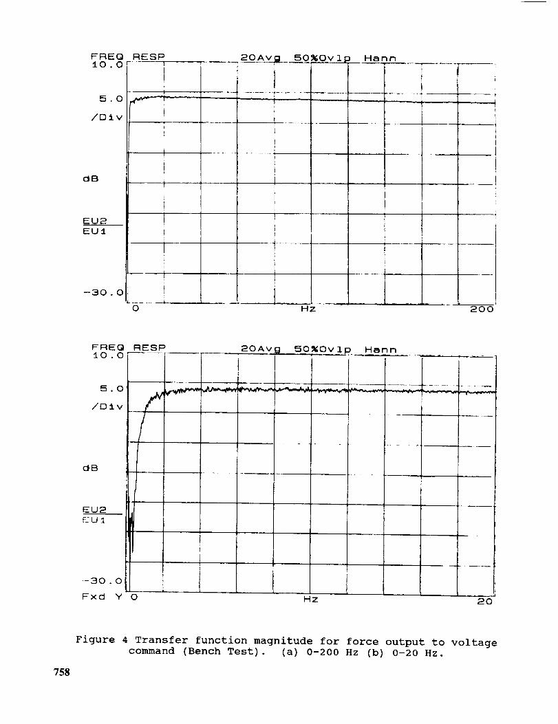
Tests of the actuator show that this device performs very well
as a force command proof mass actuator over a large frequencyrange. Figures 4 a,b show the measured transfer function from
voltage input to force output (as measured by an accelerometer) for
the actuator mounted in a bench test. The input used here is a one
volt random input. The force output level is approximately 1.6
Ib/v. As seen, the force output is extremely flat from about 2 Hz
to over 200 Hz. The phase plot (not shown here) is generally quite
flat but does exhibit noticeable phase shift at frequencies below
about 5 Hz. In initial tests, the proof mass was not exactly
centered on the axis of the moving coil. This produced noticed
ripples in the response curves starting at about 50 Hz due to
exciting structural dynamics of the actuator frame. Centering the
mass produces the smooth response shown in the figure. Linearity
of the device was tested by applying a sinusoidal voltage and
plotting the voltage -force relationship. These results are shown
in Figure 5. If perfectly linear, the curve should be a straight
line. As seen in the figure there is slight non-linearity, and a
small amount of hysteresis, but overall we judge the response to be
extremely good.
Several of these actuators have been constructed and mounted on
a five meter test structure in the Structural Dynamics Research
Laboratory at the University of Cincinnati. The truss structure is
shown in Figure 6. The bench tests previously described were
754

repeated on the test structure to verify that the proof mass
actuator continued to operate as expected when subjected to the
dynamics of the truss frame. The truss is mounted vertically and
suspended from the ceiling to simulate a free-free horizontal
suspension. A number of large aluminum plates are used as
attachment points for the actuators described here. The large
masses on the truss produce a set of dynamics with significant
modes at low frequency. A typical frequency response of
acceleration response to force input at one of the actuator
mounting points is shown in Figure 7. Numerous modes exist on the
truss throughout the frequency range tested. The bench test shown
in Figure 4 was repeated with the actuator mounted on the
structure. These results are shown in Figure 8. There is very
little difference between the two sets of curves, indicating that
the actuator dynamics have negligible interaction with the truss
dynamics.
Conclusions
The intent of this paper is to present the details of the
construction of a low cost proof mass actuator, suitable for
research into the dynamics and control of large flexible
structures. The actuators were constructed from surplus disk drive
actuators for a relatively modest cost. Neglecting the cost of the
drive (which we in fact obtained at no cost) the total expenditure
for equipment was less than about three hundred dollars. (Normally
the surplus disk drive itself may cost a comparable amount if
purchased). The analysis and test results show how this relatively
simple concept can be used as a highly effective linear proof mass
actuator suitable for control purposes, or as a mechanical shaker.
We have constructed over five of these systems and their
performance is fairly reliable and repeatable. Current studies are
under way to use these actuators in on-line identification schemes
for structures and for vibration suppression control experiments.
References
,
.
.
J.Sulla,J-N Juang, L. Horta, "Analysis and Application of
a Velocity Command Motor as a Reaction Mass Actuator",
AIAA Dynamics Specialist Conf., Long Beach, CA, 1990.
J. Sharkey, H. Waites, G. Doane, "Distributed Control
using Linear Momemtum Control Devices", NASA TM-100308,
October, 1987.
D. C. Zimmerman, D. J. Inman, "On the Nature of the
Interaction Between Structures and Proof-Mass Actuators,
J. of Guidance, Control, and Dynamics, Vol. 13, Jan-Feb,1990.
755
,,").?_._ _N 2..L FAGE
_,LACK A_'q'D V'./H!T£ PHOTOGI_APH
Figure 1 Proof Mass Actuator
K,K,[Mv
GvKv +S _2
Figure 2 Block diagram of actuator feedback loop
756

-_1,?' 'v'
! T
I
4F B
:",_e_
i
-T
__ 4,' _
1
-i ....
10 L'
{
• i _,
T
I
_ $
1[ ;,
transducer
i
100 k 33(':'
i
OUt['J!
Figure 30p-amp circuit for conditioning of sensor signals to input
amplifier
757
FREQ RESP_0 0 r ..... r------_'---_
• I --,
!
5.0 """_-'Y_ - " " 1t
t/D±v
OB
EU2EU:I
--30 . 0I
....... 1
0
20Av 50_Ov 1 Hahn
I ..... I
HZ .... L---200'
F FIEI3 FIESP10 . 0 ---'
5.0
/Dtv
20Av _1 50_Ov 1,p.__Han n
"r T i
dB
EU2EU1
--:30 . 0
Fxd Y 0 Hz 20
Figure 4 Transfer function magnitude for force output to voltage
command (Bench Test). (a) 0-200 Hz (b) 0-20 Hz.
758

ORBITSB.O
EU1
1 2%0v 1 p
1 I .... I
b|
l !--B.O
Fx(:l X -_0.5 '10 /I-
Figure 5 Force-voltage curve showing linearity of the actuator.
(Reference signal is 5 v at 20 Hz.)
759

ULACK ..... '2' T,E
Figure 6 Laboratory truss structure used in test
F' _ _. Q i-:.tL! _ r _:o.o[ ......
I
tO.O
,'[3 i'.
d_
F__UR
t i
!il
'I
20Avg 50%0vI Hann Ov;;
' / "--
t,__._, //f .........
k
i,
I'
I
760
--'o .oL-___ _. IL_
0 k4z
Figure 7 Frequency response of the truss structure
(Acceleration/force)
2o

..... l I !
.... i
50_Ov lp Harm
d i3
1
I........ i .....
0
i
I L I
i 1. L L_ J . [ ,_!z 200
F: F_IE QiO.Or
l
5.0
/23 i v
d_
EUP
--30 . O
20A"9 50%Ovlp k_ann OvP
LI
- l .......
0 H z
!• !
I m
i
I
I
I
ir
L_o
Figure 8 Transfer function magnitude for force output to voltage
command (On structure). (a) 0-200 Hz (b) 0-20 Hz.
761
