analysis of disc break by using fea and · pdf fileanalysis of disc break by using fea and...
TRANSCRIPT
International Journal of Advances in Applied
Science and Engineering (IJAEAS)
ISSN (P): 2348-1811; ISSN (E): 2348-182X
Vol-1, Iss.-3, JUNE 2014, 136-142
© IIST
International Journal of Advances in Engineering and Applied Science Vol-1, Iss-3, 2014
136
ANALYSIS OF DISC BREAK BY USING FEA AND ANSYS
R.LAKSHMANAIK1,DR. T. DHARMA RAJU2,T. JAYANAND3
1PG Student (M.Tech–CAD/CAM), Dept. of ME, GIET Rajahmundry, AP, India
2Professor, Dept.of ME, GIET Rajahmundry, AP, India
3Associate Professor, Dept.of ME, GIET Rajahmundry, AP, India
ABSTRACT: A transient analysis for the thermo elastic contact problem of the disk brakes with heat generation is performed using the finite
element analysis. To analyze the thermo elastic phenomenon occurring in the disk brakes, the occupied heat conduction and elastic equations are
solved with contact problems.
The numerical simulation for the thermo elastic behavior of disk brake is obtained in the repeated brake condition. The computational
results are presented for the distribution of heat flux and temperature on each friction surface between the contacting bodies. Also, thermo elastic
instability (TIE) phenomenon (the unstable growth of contact pressure and temperature) is investigated in the present study, and the influence of the
material properties on the thermo elastic behaviors (the maximum temperature on the friction surfaces) is investigated to facilitate the conceptual
design of the disk brake system. Based on these numerical results, the thermo elastic behaviors of the carbon-carbon composites with excellent
mechanical properties are also discussed.
KEYWORDS: Disc Brake, Structural Analysis, Thermal analysis, FEA, Ansys.
1. INTRODUCTION
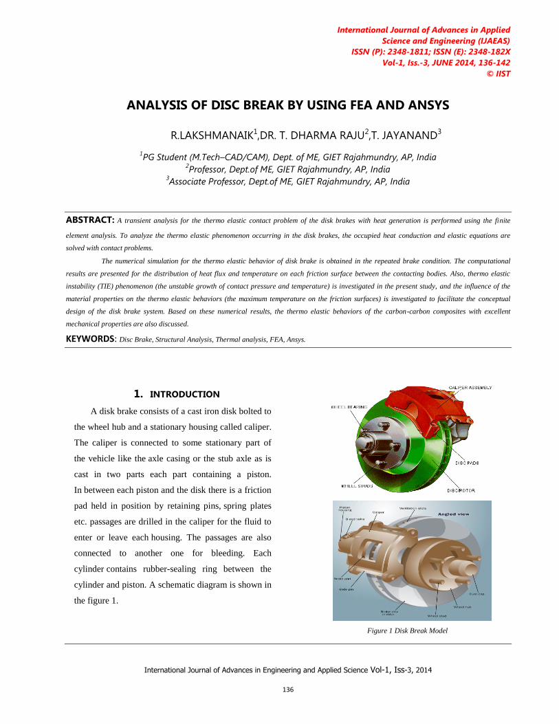
A disk brake consists of a cast iron disk bolted to
the wheel hub and a stationary housing called caliper.
The caliper is connected to some stationary part of
the vehicle like the axle casing or the stub axle as is
cast in two parts each part containing a piston.
In between each piston and the disk there is a friction
pad held in position by retaining pins, spring plates
etc. passages are drilled in the caliper for the fluid to
enter or leave each housing. The passages are also
connected to another one for bleeding. Each
cylinder contains rubber-sealing ring between the
cylinder and piston. A schematic diagram is shown in
the figure 1.
Figure 1 Disk Break Model

Material Selection Method in Design of Automotive Disc Brake
International Journal of Advances in Engineering and Applied Science Vol-1, Iss-3, 2014
137
When the brakes are applied, hydraulically actuated
pistons move the friction pads in to contact with the
rotating disk, applying equal and opposite forces on the
disk. Due to the friction in between disk and pad
surfaces, the kinetic energy of the rotating wheel is
converted into heat, by which vehicle is to stop after a
certain distance. On releasing the brakes the brakes the
rubber-sealing ring acts as return spring and retract the
pistons and the friction pads away from the disk.
In the course of brake operation, frictional heat is
dissipated mostly into pads and a disk, and an
occasional uneven temperature distribution on the
components could induce severe thermo elastic
distortion of the disk.
Ansys is useful software for design analysis in
mechanical engineering. That’s an introduction for you
who would like to learn more about Ansys. Ansys is a
design analysis automation application fully integrated
with Pro-Engineer. This software uses the Finite
Element Method (FEM) to simulate the working
conditions of your designs and predict their behavior.
FEM requires the solution of large systems of
equations.
Powered by fast solvers, Ansys makes it possible for
designers to quickly check the integrity of their designs
and search for the optimum solution.
A product development cycle typically includes the
following steps:
• Build your model in the Pro-Engineer system.
• Prototype the design.
• Test the prototype in the field.
• Evaluate the results of the field tests.
• Modify the design based on the field test results
2. MATERIAL PROPERTIES
The Disc brake discs are commonly manufactured out of
grey cast iron. The SAE maintains a specification for the
manufacture of grey iron for various applications. For
normal car and light truck applications, the SAE
specification is J431 G3000 (superseded to G10). This
specification dictates the correct range of hardness,
chemical composi-tion, tensile strength, and other
properties necessary for the intended use. Some racing
cars and airplanes use brakes with carbon fiber discs and
carbon fiber pads to reduce weight. Wear rates tend to be
high, and braking may be poor or grabby until the brake
is hot. The mate-rials used for rotor disc are explained in
detail.
It is investigated the temperature distribution, the
thermal deformation, and the thermal stress of automotive
brake disks have quite close relations with car safety;
therefore, much research in this field has been performed.
3. PERFORMANCE EVALUATION
Due to the application of brakes on the car disk brake
rotor, heat generation takes place due to friction and
this thermal flux has to be conducted and dispersed
across the disk rotor cross section. The condition of
braking is very much severe and thus the thermal
analysis has to be carried out.
Cast Iron Properties:
Material Properties Pad Disk
Thermal conductivity, K
(w/m k) 5 57
Density ( kg/m3) 1400 7100
Specific heat , c (J/Kg k) 1000 452
Poisson’s ratio, v 0.25 0.25
Thermal expansion , á
(106 / k ) 10 11
Elastic modulus, E (GPa) 1 106
Coefficient of friction, µ 0.0667
Material Selection Method in Design of Automotive Disc Brake
International Journal of Advances in Engineering and Applied Science Vol-1, Iss-3, 2014
138
Operation Conditions
Angular velocity, ù (rad/s) 150
Hydraulic pressure, P
(Mpa) 1
The thermal loading as well as structure is axis-
symmetric. Hence axis-symmetric analysis can be
performed, but in this study we performed 3-D
analysis, which is an exact representation for this
thermal analysis. Thermal analysis is carried out and
with the above load structural analysis is also
performed for analyzing the stability of the structure.
Stain less steel Properties:
Material Properties Pad Disk
Thermal conductivity, K (w/m
k) 5 17.2
Density, ( kg/m3) 1400 7800
Specific heat , c(J/Kg k) 1000 500
Poisson’s ratio, v 0.25 0.3
Thermal expansion , á
(106 / k ) 10 16
Elastic modulus, E(GPa) 1 190
Coefficient of friction, µ 0.0667
Operation Conditions
Angular velocity, ù(rad/s) 150
Hydraulic pressure, P(Mpa) 1
Figure 2 Dimensions of 24mm Disk Brake
The dimensions of brake disk used for
transient thermal and static structural analysis are
shown in Fig.2.
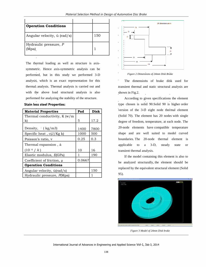
According to given specifications the element
type chosen is solid 90.Solid 90 is higher order
version of the 3-D eight node thermal element
(Solid 70). The element has 20 nodes with single
degree of freedom, temperature, at each node. The
20-node elements have compatible temperature
shape and are well suited to model curved
boundaries. The 20-node thermal element is
applicable to a 3-D, steady state or
transient thermal analysis.
If the model containing this element is also to
be analyzed structurally, the element should be
replaced by the equivalent structural element (Solid
95).
Figure 3 Model of 24mm Disk brake

Material Selection Method in Design of Automotive Disc Brake
International Journal of Advances in Engineering and Applied Science Vol-1, Iss-3, 2014
139
As shown in Fig. 4 a model presents a three
dimensional solid disk squeezed by two finite-width
friction material called pads. The entire surface, S, of
the disk has three different regions including S1 and
S2. On S1 heat flux is specified due to the frictional
heating between the pads and disk, and S2 is defined
for the convection boundary. The rest of the region,
except S1 U S2, is either temperature specified or
assumed to be insulated: the inner and outer rim area
of disk.
Figure 4 Thermal model
In the contact region S1, the local shear traction cause
frictional heating that flows into the disk and pads.
Heat flux q on a contact area is updated per the
pressure distribution at every simulation step
* * * * *q V p r P
Where µ is the coefficient of friction, V the sliding
speed, P the contact pressure, and ù is used for angular
velocity. In the solution procedure, frontal solver is
used. It involves two steps. After the individual element
matrices are calculated, the solver reads in the degree of
freedom (DOF) for the first element.
The program eliminates any degrees of freedom that can
be expressed in terms of the other DOF by writing an
equation to the .TRI file. This process repeats for all the
elements until all the degree of freedom have been
eliminated and a complete triangular zed matrix is left
on the .TRI file.
The term frequently used is the frontal solver is
wave front. The wave front is the number of degrees of
freedom retained by the solver while triangularization
of the matrix.
The nodal solution plots of temperature distribution
in thermal analysis. Graph of the temperature variation
with respect to the radial distance from the point of
application of the heat flux. Graph of the temperature
variation with respect to the time. The nodal solution
plot of Stress distribution in structural analysis.
(a) 1st braking (b) 4th braking

Material Selection Method in Design of Automotive Disc Brake
International Journal of Advances in Engineering and Applied Science Vol-1, Iss-3, 2014
140
(C) 7TH BRAKING (D) 10TH BRAKING
Figure 5 Temperature contours of 16mm Cast Iron disk (a)-(d)
(A) 1
ST BRAKING (B) 4
TH BRAKING
(C) 7
TH BRAKING (D) 10
TH BRAKING
Figure 6. Temperature contours of 16mm Stainless Steel disk (a)-(d)

Material Selection Method in Design of Automotive Disc Brake
International Journal of Advances in Engineering and Applied Science Vol-1, Iss-3, 2014
141
Figure 7. Distribution of Von misses Stress in 24 mm Cast iron & Stainless Steel Disk
Figure 8. Distribution of Hoop Stress in 24 mm Cast iron & Stainless Steel Disk
Figure 9. Average displacement in 24 mm Cast iron & Stainless Steel Disk

Material Selection Method in Design of Automotive Disc Brake
International Journal of Advances in Engineering and Applied Science Vol-1, Iss-3, 2014
142
4. CONCLUSIONS
By observing the Structural analysis and Thermal
analysis results using cast iron and Stainless steel the
stress values are within the permissible stress value. So
using these alloys is safe for Disc Brake. By observing
the frequency analysis, the vibrations are less for cast
iron Alloy than other two materials since its natural
frequency is less. And also weight of the cast iron alloy
reduces almost 3 times when compared with stainless
steel since its density is very less. Thereby mechanical
efficiency will be increased. But the strength of Cast
iron material is more than steel Alloy. Even from the
Thermal Analysis also Cast Iron is also permissible. By
observing analysis results, cast iron is best material for
Disc Brake.
5. ACKNOWLEDGEMENTS
The authors would like to thank the anonymous
reviewers for their comments which were very helpful
in improving the quality and presentation of this paper.
6. REFERENCES:
1]BRILLA, J. Laplace Transform and New Mathematical Theory of Visco elasticity,vol. 32, page 187- 195, (1997).
2]WANG, H. -C. AND BANERJEE, P. K.. Generalized Axis
symmetric Elastodynamic Analysis by Boundary Element Method,
vol. 30, page 115-131, (1990).
3]ZIENKIEWICZ, O. C. The Finite Element method, McGraw-Hill,
New York, (1977).
4]BEEKER, A.A. The Boundary Element Method in Engineering,
McGraw-Hill,New York, (1992).
5]FLOQUET, A. AND DUBOURG, M.-C. Non axis symmetric effects
for three dimensional Analyses of a Brake, ASME J. Tribology, vol. 116, page 401-407(1994).
6]J.O.Nordiana, S.O.Ogbeide, N.N.Ehigiamusoe and F.I.Anyasi., 2007,”Computer aided design of a spur gear, “Journal of
Engineering and Applied Sciences 2 (12); pp 1743 1747.
7]Zeping Wei., 2004”Stresses and Deformations in Involute spur
gears by Finite Element method,” M.S, Thesis, College of Graduate
Studiesand research, University of Saskatchewan,
8]Darle W.Dudley, 1954, Hand book of practical gear design Alec
strokes, 1970, High performance of gear design.