analysis of face stability during excavation of double-o-tube shield tunnel · 2017-05-09 ·...
TRANSCRIPT
Hindawi Publishing CorporationThe Scientific World JournalVolume 2013 Article ID 781968 11 pageshttpdxdoiorg1011552013781968
Research ArticleAnalysis of Face Stability during Excavation ofDouble-O-Tube Shield Tunnel
Yuyou Yang1 Qinghong Zhou12 Hongan Li1 Xuegang Huang1 and Xiaoming Tu1
1 School of Engineering and Technology China University of Geosciences (Beijing) Beijing 100083 China2Haikou Forest Farm Kunming Yunnan 650114 China
Correspondence should be addressed to Yuyou Yang yangyuyoucugbeducn
Received 3 July 2013 Accepted 7 August 2013
Academic Editors A Arulrajah and J Chu
Copyright copy 2013 Yuyou Yang et al This is an open access article distributed under the Creative Commons Attribution Licensewhich permits unrestricted use distribution and reproduction in any medium provided the original work is properly cited
This paper focuses on the face stability analysis of Double-O-Tube shield tunnel This kind of analysis is significant to ensure thesafety of workers and reduce the influence on the surrounding environment The key point of the stability analysis is to determinethe supporting pressure applied to the face by the shield A collapse failure will occur when the supporting pressure is not sufficientto prevent themovement of the soil mass towards the tunnel A three-dimensional collapse failuremechanismwas presented in thispaper Based on the mechanism of a single circular shield tunnel the mechanism of Double-O-Tube shield tunnel was establishedby using the fact that both of the mechanisms are symmetrical Then by means of the kinematic theorem of limit analysis thenumerical results were obtained and a design chart was providedThe finite difference software FLAC3Dwas applied to investigatethe face failure mechanism of DOT shield tunnel established in this paper the critical supporting pressures of the collapse failuremechanism in different strata (sand and silt) were calculated Through comparative analysis the theoretical values were very closeto the numerical valuesThis shows that the face failure mechanism of DOT shield tunnel is reasonable and it can be applied to thesand and silt strata
1 Introduction
Compared with the single circular shield tunnel the Double-O-Tube (DOT) shield tunnel has many advantages for exam-ple (i) optimizing use of the underground space (ii) savingconstruction cost and time and (iii) reducing the impact onnearby structures In 1989 Japan took the lead in adopting theDOT shield technology for a subway project inHiroshima [1]In the following ten years more than ten DOT shield tunnelshave been built in Japan for example Nagoya express railwaytunnel then China first applied the DOT shield technologyin the construction of Shanghai rail transit projects from 2002to 2006 [2 3] In 2009 the Taoyuan International AirportAccess Mass Rapid Transit system in Taipei Taiwan wasconstructed by the DOT shield machine [4] With the rapiddevelopment of underground engineering in urban areathere will be more DOT shield tunnels in the future
The stability analysis of a tunnel driven by a pressurizedshield is a key issue in real shield tunneling projects Duringthe construction of a tunnel the collapse failure at the cutter
face will lead to the settlement of ground surface which maycause damage to the surrounding buildings Ensuring tunnelface safety requires the determination of the supportingpressure applied to the face by the shield The DOT shield isan earth pressure balance type shield inwhich the supportingpressure is applied by controlling the moving speed of screwInvestigation of the face stability of circular tunnels has beenconducted by several authors in the literature Leca andDormieux proposed twomechanisms for the collapse failureone contained a single conical block the other one wascomposed of two conical blocks [5] Soubra et al proposedan optimizedmechanismwhichwas composed of five conicalblocks that allow the 3D slip surfaces to develop more freely[6] Then the mechanism by Mollon et al was generatedldquopoint by pointrdquo instead of the simple use of existing standardgeometric shapes such as cones or cylinders All of these sig-nificant approaches are translational three-dimensional fail-ure mechanisms and are based on the kinematical approachof limit analysis [7] In addition some scholars have studiedthis issue by experiments and numerical methods Chambon
2 The Scientific World Journal
and Corte carried out the centrifuge tests the experimentalresults show that the collapse failure surface is similar toa chimney that does not necessarily outcrop at the groundsurface [8] Yang and Li proposed a three-dimensional col-lapse failure mechanism and investigated the ground surfacesettlements and failure mechanism above large-diametershield tunnels under different supporting pressures [9] Yanget al did some research about soil improvement techniquesto guarantee the stability of excavation face [10 11] In orderto observe the contour of failure surface Takano et al usedX-ray computed tomography scanner it was suggested thatthe contour of the failure surface can be simulated with twolog-spirals in the vertical cross-sections and elliptical contourin the horizontal cross-sectionsThese experiments are bene-ficial to establish the more optimized analytical mechanisms[12] Wei et al used the finite element software MIDASGTSto simulate the construction process of the Double-O-Tube(DOT) shield tunnel and analyzed the building-soil-tunnelinteraction [13]
This paper focuses on the face stability analysis of DOTtunnels The biggest challenge of this kind of analysis is toestablish a failure mechanism It is necessary to note thatthe generation of the mechanism associating with the DOTtunnel can be developed from that of a single circular tunnelThis can be achieved if one realized that both themechanismsare symmetrical Detailed modeling progress of the DOTshield tunnels will be described later The face stability analy-sis requires the determination of the supporting pressure thatis applied to the tunnel face by the shield to ensure the stabilityof tunnel face and limit environmental impact A three-dimensional collapse failure mechanism was presented andthe kinematical approach of the limit analysis theorywas usedto calculate the critical supporting pressures A design chartwas provided in the aim of computing the collapse pressuresexpediently Then the finite difference software FLAC3D wasapplied to investigate the face failure mechanism of DOTshield tunnel established in this paper and the results werepresented
2 Limit Analysis in Tunnel Face Stability
Limit analysis was first presented in terms of the theorems byDrucker et al to estimate the critical height of slope it alsocan be used to evaluate bounds on the limit load inducingor resisting failure in structures built of perfectly plasticmaterials [14 15] The aim of tunnel face stability analysis isto ensure that the supporting pressure is sufficient to pretendthe soil mass collapse in front of the tunnel face In fact thekey point of the analysis is to determine the lower boundpressures Hence the face stability analysis is a typical limitstate problem The kinematic theorem of limit analysis isknown as the ldquoupper bound theoremrdquo because it can be statedas ldquothe power of external loads applied to the structure islarger than the power that dissipated in the structure duringits failurerdquo Generally it can be described in the followingmathematical form
int119881
( 120576119894119895) 119889119881 ge int
119878V
119879119894V119894119889119878V + int
119878119905
119879119894V119894119889119878119905+ int119881
120574119894V119894119889119881
(1)
The left side of (1) represents the rate of work dissipationduring an incipient failure of a structure and the right sideincludes the work rates of all external forces 119879
119894is the stress
vector on boundaries 119878V and 119878119905 Vector 119879
119894is unknown (limit
load) on 119878V and it is known on 119878119905(for instance surcharge
pressure) V119894is the velocity vector in the kinematically admis-
sible mechanism 120574119894is specific weight vector and 119881 is the
volume of the mechanism [16]The collapse failure will occurif the supporting pressure is lower than the critical pressureIn this case the supporting pressure is not a load becauseit prevents the failure to appear This can explain the puzzlethe ldquoupper bound theoremrdquo is applied to calculate the lowerbound critical pressure
In order to apply the limit analysis some assumptionsmust be given (i) the strain rates resulting from the velocityfield must satisfy the flow rule (ii) the failure must complywith the Mohr-Coulomb yield condition which containstwo material constants the internal friction angle 120593 and thecohesion intercept 119888 According to the normality conditionfor an associated flow rule Coulombmaterial for a kinemati-cally admissible failuremechanism the velocity discontinuityalong a plastically deformed surface must make an angle 120593with this velocity discontinuity surface [17]
In this paper the external loads acting on the collapsefailure mechanism contain (i) the self-weight of the soil (ii)the pressure 120590
119905acting on the tunnel face (iii) the possible
surcharge loading 120590119904acting on the ground surface (if the
mechanism outcrops) Then the kinematic theorem of limitanalysis can be written in the following mathematical form
119863 = 119882120574+ 119882120590119905
+ 119882120590119904
(2)
where 119863 represents the rate of internal energy dissipation119882120574 119882120590119905
and 119882120590119904
represent the rate of work of the soil self-weight the rate of work of the applied pressure and the rateof work of the possible surcharge respectively
The rate of work of the soil weight is calculated from ageneral expression as in
119882120574= ∭
119881
V119894120574119894119889119881 (3)
where V119894and 120574
119894are the velocity vector and the unit weight
vector respectively and 119881 are the volume of the mechanism(below the ground surface)
The Rate of work of the pressure 120590119905is calculated from a
general expression as in
119882120590119905
= minus120590119905∬119878
V119894119889119878 = minus120590
119905V cos120573119860
119879 (4)
where 119860119879are the area of intersection of the tunnel face with
the lower coneThe rate of work of the possible uniform surcharge 120590
119904
acting on the ground surface is calculated from a generalexpression as in
119882120590119904
= 120590119904∬119878
V119894119889119878 = 120590
119904V sin120573119860
119878 (5)
where119860119878are the possible area of the intersection of themech-
anism with ground surface
The Scientific World Journal 3
Considering that the mechanism is rigid the only sourceof energy dissipation is derived from the plastic soil deforma-tion that occurs along the velocity discontinuity surface Therate of internal energy dissipation is calculated from a generalexpression as in
119863 = ∬119878
119888V119894cos120593119889119878 (6)
where S is the superficial area of the mechanism (belowthe ground surface) It should be mentioned here that thecomputation of energy dissipation could be made using analternative convenient approach (for more details see [17])
By equating the total rate of external forces (3)ndash(5) to thetotal rate of internal energy dissipation (6) the pressure 120590
119905
can be expressed as follows
120590119905= 120574119863119873
120574+ 120590119904119873119904minus 119888119873119888 (7)
where 119873120574 119873119888 and 119873
119904are nondimensional coefficients rep-
resenting respectively the effect of soil self-weight cohesionand surcharge loading
3 The 3D Collapse Failure Mechanism
31 Geometrical Construction of the 3D Failure MechanismAs mentioned previously the generation of the mechanismassociating with the DOT tunnel is based on that of asingle circular tunnel To better introduce the geometricalconstruction of the 3D failuremechanism of the DOT tunnelit is necessary to introduce that of a single circular tunnel atfirst Figure 1 shows the cross-section of themechanism in thevertical plane passing through the tunnel axis The diameterof the tunnel is 119863 and 119862 represents the cover depth Asshown in Figure 1 themechanism is composed of a truncatedconical block and a rotational curvilinear cone (the shapeof the cone is like a ldquohornrdquo) and the ldquohornrdquo is located onthe conical block the contacting cross-section Σ
1is circular
The opening angle of the conical block is equal to 2120593 Therotational curvilinear cone can be described by two log spirals1199031and 1199032 which emerg from 119860 and 119864 respectively and share
a common center 119874 The two log spirals intersect at point 119865Their respective equations in a polar (119903 120573) coordinate systemare as follows
1199031= 119903119860
sdot exp ((120572 minus 120573) sdot tan120593) 1199032= 119903119864sdot exp ((120573 minus 120572) sdot tan120593) (8)
where 119903119860and 119903119864represent the distance between119874 and 119860 and
119864 respectively The central point 119874 is located 119863119899 above thetunnel as shown in Figure 1 Consider that
119903119860
= 1119899 cos120572 sdot 119863
119903119864= [ 1
119899 cos120572 + cos (120572 + 120593)cos120593 ] sdot 119863
(9)
The character of the ldquohornrdquo contains (i) each radial cross-section is circular with the diameter (119903
2minus 1199031) (ii) the apex
angle of the horn equals 2120593 (iii) there is a vertical symmetryplane passing through the tunnel axis The mechanism iskinematical admissibility which requires along the entiresliding surface the velocity of the rotating soil to be inclinedat angle 120593 to the surface this assures that the dilatancy (vol-ume increase) of the shearing soil is accommodated by themechanism This dilatancy is the direct consequence of theMohr-Coulomb yield condition and the normality flow ruleTo satisfy this admissibility requirement the apex angle of theldquohornrdquo needs to be equal to 2120593 It is obvious that the shape ofthe mechanism depends on three variables 120593 119899 and 120572
Then based on the study of single-circular tunnel themechanism can be modified with plane inserts to ensuretransition to a planemechanismwith an increase in the widthof the insertThe generating progress of the mechanism asso-ciating with the DOT tunnel is shown in Figure 2 Excitingthe vertical symmetry plane allows the mechanism to extendalong the width direction
32 Velocity Field At first the velocity in the rotation sectionis introduced The velocity direction is normal to the radialplanes and themagnitude is a function of radius 119903
119898and angle
120573 as shown in
V = sdot 119903119898 (10)
where120596 is the angular velocity about the axis passing throughpoint 119874 and
119903119898
= 1199031+ 1199032
2 (11)
As shown in Figure 1 V1is the velocity of the conical
block For the calculation of the rate of wok of these forcesV1must be expressed in terms of the angular velocity 120596 To
solve this problem one can use the fact that the contactingcross section Σ
1is circular The velocity of point 119868 which is
the centre of plane Σ1 is shown in
V119868= sdot 119903
119868 (12)
where
119903119868= 119903119860
+ 119903119864
2 = [ 1119899 cos120572 + cos (120572 + 120593)
2 cos120593 ] sdot 119863 (13)
At the same time considering the fact that V119868= V1 then
the expression of V1can be obtained as follows
V1= sdot [ 1
119899 cos120572 + cos (120572 + 120593)2 cos120593 ] sdot 119863 (14)
4 Numerical Results
41 Limit Supporting Pressures Based on the kinematicalapproach of limit analysis theory in tunnel face stabilitythe previouslymentioned three non-dimensional coefficients(119873120574 119873119888 and 119873
119904) can be obtained As mentioned previously
for the same 120593 the mechanism is different along with thechange of the values of 119899 and 120572 However the change of119873
120574is
4 The Scientific World Journal
Ground surface
C
D
Dn
120590t
120573
120572
y1
F
r1
A
x
y
Ω
Y
ZZ1
x
x
y
y
r2
minusrarrV
minusrarrV1
O
O998400
E
B
I
Tunnel
120593 120593
120593120593
Intersection of the failure mechanismwith the tunnel faceΣ1
Figure 1 Cross-section of the collapse failure mechanism associating with a single circular tunnel in the (119910 119911) plane
D
Symmetry plane Plane insert
WD
Figure 2 The evolutionary progress of the collapse failure mecha-nism from a single circular tunnel to DOT tunnel
tiny when 119899 gt 35 The results are optimized when 120572 = 30∘So the numerical results presented in this paper are obtainedfor 119899 = 35 120572 = 30∘
The values of 119873120574and 119873
119888are provided in Figures 3 and
4 respectively Table 1 presents the collapse pressures for twodrained clays (i) 119888 = 5 kPa and 120593 = 15∘ (soft clay) (ii) 119888 =12 kPa and 120593 = 30∘ (stiff clay) The presented critical collapsepressures are calculated for the diameter of the tunnel that isequal to 10m and 120574 = 18 kNm3 It is necessary to note thatwhen the overburden ratio is high enough (119862119863 gt 05) themechanism is always with nooutcrop It is the reason why thecoefficient 119873
119904is equal to zero and 119873
120574and 119873
119888are constant
with the increase of 119862119863
Table 1 Critical collapse pressures of given soil parameters
Soft clay (119888 = 5 kPa 120593 = 15∘) Stiff clay (119888 = 12 120593 = 30∘)119873120574
0442 0155119873119888
3732 1732119873119904
0 0120590119888
60878 kPa 7175 kPa
42 Design Chart In order to make the numerical resultsassociated with the proposed mechanism can be used expe-diently to compute the collapse pressures a design chart isprovided in Figure 3 The equation of each line in Figure 5 ispresented in (15) It is obvious that the intercept on verticalcoordinate represents the values of 119873
120574 and the slope of
the line represents the values of 119873119888 Notice that the design
chart also can be used to compute the required tunnelface supporting pressure when the safety factor 119865
119878is given
The safety factor 119865119878is defined with respect to the two soil
parameters 119888 and tan120593 This may be achieved if one uses thechart with 119888
119889and 120593
119889instead of 119888 and 120593 where 119888
119889and 120593
119889are
based on the following equations120590119888
120574119863 = 119873120574minus 119888
120574119863 sdot 119873119888 (15)
119888119889= 119888
119865119878
(16)
120593119889= arctan( tan120593
119865119878
) (17)
The Scientific World Journal 5
005
015
025
035
045
00 10 20 30
N120574
CD
120593 = 15∘
120593 = 20∘
120593 = 25∘
120593 = 30∘
120593 = 35∘
Figure 3 The values of 119873120574
10
15
20
25
30
35
40
00 10 20 30CD
Nc
120593 = 15∘
120593 = 20∘
120593 = 25∘
120593 = 30∘
120593 = 35∘
Figure 4 The values of 119873119888
5 Numerical Analysis for Failure Mechanismof DOT Shield Tunnel Face
In order to verify the applicability of failure mechanism ofDOT shield face established in this paper the application ofthe failure mechanism used for sand and silt layers was ana-lyzed and the critical supporting pressures of collapse failuremechanism in different strata were calculated And then thenumerical results and theoretical results were comparativelyanalyzed to illustrate whether the failure mechanism is appli-cable In the numerical calculation the supporting pressureat the central of the tunnel face is taken to represent the mag-nitude of the face supporting pressure In order to facilitatethe description the conception of supporting pressure ratio
120593 = 15∘
120593 = 20∘
120593 = 25∘
120593 = 30∘
120593 = 35∘
00
01
02
03
04
05
000 002 004 006 008 010 012c120574D
120590c120574D
Figure 5 Design chart of critical pressure
(SPR) is introduced to measure the magnitude of the facesupporting pressure [18] namely
120582 = 120590119905
1205900
(18)
where 120590119905is thesupporting pressure of tunnel face 120590
0is the
earth pressure at rest of tunnel face
51 Simulation of the Construction Mechanical Behavior ofDOT Shield Tunnel In this paper the collapse failure oftunnel face and surface settlement caused by the impropersupporting pressure during the shield tunnel constructionare investigated to calculate the critical supporting pressureof tunnel face when the collapse failure occurs Thereforethe finite difference software FLAC3D which can reflect thelarge deformation of the rock mass was applied to simulatethe excavation process of DOT shield tunnel The lagrangianmethod follows the assumption of a continuous medium itallows the medium to large deformation and can reflect thegeometric large deformation problems
During the shield tunnel construction the soil excava-tion shield driving segment installation and tail groutingare a continuous cycle The influence of different supportingpressure on the excavated surface deformation destructionsand the surface subsidence is the focus of the analysis inthis paper Therefore the excavation process is simulatedusing a simplified single-step excavation scheme assumingthat the tunnel is excavated a certain distance instantaneouslyand the supporting structure is installed And then the facesupporting pressure is reduced gradually the influence ofthe magnitude of the face supporting pressure on the sur-rounding soil deformation is investigated Such a simplifiedmodeling scheme has been successfully adopted in previousstudies [19 20] When grouting at shield tail cement slurryfills gaps and infiltrates into soil mass then gradually hardensIn this process soil and cement slurry form a mixture whosemechanical properties are affected by nature of soil cementslurry material and amount and pressure of grouting In
6 The Scientific World Journal
Block groupExcavated soilTunnel liningGroutSoil
(a) Three-dimensional meshes
XY
Z
(b) Meshes of the excavation unit
XY
Z
XY
Z
(c) Meshes of the lining unit
Figure 6 Meshes of the computing model
real analysis it is very difficult to analyze quantitatively thesefactors Taking into account the effects of the shield tail voidthe degree of filling grout and the disturbance of soil aroundthe tunnel on the ground deformations the conception ofequivalent circle zone is used to simulate the shield tailgrouting which is a layer of homogeneous and continuouselements representing the shield tail void between the outersurface of lining and the overexcavation surface [21]
52 Three-Dimensional Model and Parameters According tothe construction conditions of DOT shield tunnel at homethe tunnel excavation diameter is 65m depth is 75mthe center distance is 46m segment is the C50 reinforcedconcrete material and thickness is 03m In order to reducethe influence of the model size on the numerical resultsthe lateral length of the three-dimensional model is 80mthe longitudinal length is 60m and the height is 35m Themodel has 28652 nodes and 52850 unitsThree-dimensionalmodel meshes excavation unit and lining unit are shown inFigure 6 The surface boundary in the present model is freewhile the bottom boundary of the model is fully fixed infour vertical boundaries all horizontal displacements normalto the boundary are constrained to be zero and the verticaldisplacement is free The tunnel is constructed from thevertical start boundary at 119910 = 0m in the positive 119910-directionAn elastic perfectly plastic constitutive model based on theMohr-Coulomb criterion is adopted to simulate deformationstrength and failure behavior of the soil the lining ismodeledusing continuous elements and it is governed by a linear-elastic behavior Physical and mechanical parameters of thematerials are shown in Table 2
53 Numerical Results Analysis In this paper two formationsof sand and silt are considered the influences of differentmagnitudes of face supporting pressure on the horizontaldisplacement and failure form of DOT shield tunnel faceand surface deformation are investigated In the numericalsimulations the continuity and circularity of shield construc-tion are ignored tunnel is excavated 25m one time alongthe positive direction of the 119910-axis at the same time thesupporting structure is timely installed and the shield tailis grouting And then face supporting pressure is reducedgradually until the collapsed failure of tunnel face occursthe impact of magnitude of face supporting pressure on thesurrounding soil deformation is investigated to obtain thecritical supporting pressure of tunnel face
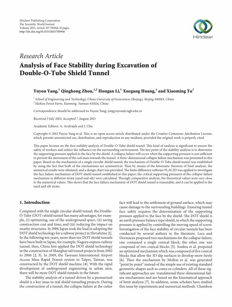
531 Analysis of the Failure Forms of the Tunnel FaceFigures 7 and 8 show the failure forms of the tunnel face afterthe face collapse of DOT shield tunnel From Figure 7 thecollapse failure occurs at the top of tunnel face in the sandstrata however the collapse failure occurs at the central oftunnel face in the silt strata FromFigure 8 it can be seen thatwhen the collapse failure tunnel face occur the affected areasin sand strata are less than the affected areas in silt strata
532 Analysis of the Critical Supporting Pressure of theTunnel Face In shield tunneling in order to reduce the soildisturbance ahead of the tunnel face the supporting pressureapplied in the tunnel face should be equal to the in situ stressat the tunnel face (ie the earth pressure at rest) When theface supporting pressure is less than the earth pressure at
The Scientific World Journal 7
Contour of displacement magPlane on behind
10083e minus 004 to 20000e minus 00120000e minus 001 to 40000e minus 00140000e minus 001 to 60000e minus 00160000e minus 001 to 80000e minus 00180000e minus 001 to 10000e + 00010000e + 000 to 12000e + 00012000e + 000 to 14000e + 00014000e + 000 to 16000e + 00016000e + 000 to 18000e + 00018000e + 000 to 19667e + 000
Interval = 20e minus 001
Magfac = 0000e + 000
(a) Sand strata
Contour of displacement magPlane on behind
23581e minus 004 to 10000e minus 00110000e minus 001 to 20000e minus 00120000e minus 001 to 30000e minus 00130000e minus 001 to 40000e minus 00140000e minus 001 to 50000e minus 00150000e minus 001 to 60000e minus 00160000e minus 001 to 64578e minus 001
Interval = 10e minus 001
Magfac = 0000e + 000
(b) Silt strata
Figure 7 Cross-sectional failure form of the tunnel face
Table 2 Physical and mechanical parameters of the materials
Material type Thickness (m) Bulk density (kNm3) Cohesion (kN) Friction angle (∘) Elastic modulus (MPa) Poissonrsquos ratioSand mdash 18 0 25 25 034Silt mdash 18 10 15 15 033C50 reinforcedconcrete lining 03 25 mdash mdash 34500 017
Tail grouting 015 165 mdash mdash 12 02
rest the face deformation occurs towards the inside of thetunnel in extreme cases the face collapse failure occurs whenthe face supporting pressure is larger than the earth pressureat rest the compressional deformation of soil in front oftunnel face occurs and the ground surface appears uplift Inthis numerical calculation the earth pressure at rest at thecenter of the tunnel face was 100 kPa The face supportingpressurewas reduced gradually and themaximumhorizontal
displacement of the tunnel face was calculated until themaximum horizontal displacement of tunnel face suddenlyincreases sharply therefore the face supporting pressure atthis time was considered as the critical supporting pressurecausing the collapse failure of tunnel face
Figure 9 shows the relationship curve between the sup-porting pressure ratio and themaximumhorizontal displace-ment of the tunnel face When the face support pressure is
8 The Scientific World Journal
Contour of displacement magPlane on behind
32135e minus 004 to 20000e minus 00120000e minus 001 to 40000e minus 00140000e minus 001 to 60000e minus 00160000e minus 001 to 80000e minus 00180000e minus 001 to 10000e + 00010000e + 000 to 12000e + 00012000e + 000 to 14000e + 00014000e + 000 to 16000e + 00016000e + 000 to 18000e + 00018000e + 000 to 19667e + 000
Interval = 20e minus 001
Magfac = 0000e + 000
(a) Sand strata
Contour of displacement magPlane on behind
25797e minus 004 to 50000e minus 00250000e minus 002 to 10000e minus 00110000e minus 001 to 15000e minus 00115000e minus 001 to 20000e minus 00120000e minus 001 to 25000e minus 00125000e minus 001 to 30000e minus 00130000e minus 001 to 35000e minus 00135000e minus 001 to 40000e minus 00140000e minus 001 to 45000e minus 00145000e minus 001 to 50000e minus 001
Magfac = 0000e + 000
(b) Silt strata
Figure 8 Longitudinal section failure form of the tunnel face
less than the earth pressure at rest with the decrease of thesupporting pressure the face deformation towards the insideof the tunnel gradually increases when the face supportpressure is greater than the earth pressure at rest with theincrease of the supporting pressure the compressional defor-mation in front of the tunnel face gradually increases In thesand strata when the supporting pressure ratio is of 02ndash10 the growth rate of the maximum horizontal displacementof the tunnel face is almost consistent when the supportingpressure ratio120582 lt 02 themaximumhorizontal displacementof the tunnel face increases sharply Therefore in the sandstrata when the face collapse failure of DOT shield tunneloccurs the critical supporting pressure ratio 120582 is consideredto be 02 namely the critical supporting pressure is 20 kPaIn the silt strata when the supporting pressure ratio 120582 is 01ndash10 the growth rate of the maximum horizontal displacementof the tunnel face increases gradually when the supporting
pressure ratio120582 lt 01 themaximumhorizontal displacementof the tunnel face increases sharply Therefore in the siltstrata when the face collapse failure of DOT shield tunneloccurs the critical supporting pressure ratio 120582 is consideredto be 01 namely the critical supporting pressure is 10 kPaWhen the face supporting pressure is greater than the criticalsupporting pressure decreasing the face supporting pressurethe face deformation is small and the face deformationin the silt strata is greater than that in the sand strataWhen the face supporting pressure is less than the criticalsupporting pressure in the sand strata decreasing supportingpressure slightly the face deformation increases rapidly orthe face collapse failure occurs in the silt strata decreasingsupporting pressure slightly the face deformation increasesrapidly but the growth rate of the horizontal displacement ofthe tunnel face is less than the growth rate of the horizontaldisplacement in the sand strata
The Scientific World Journal 9
minus500
minus400
minus300
minus200
minus100
minus010
100
0 02 04 06 08 1 12 14
Max
imum
hor
izon
tal
disp
lace
men
t of t
he tu
nnel
face
(mm
)Supporting pressure ratio
Sand strataSilt strata
Figure 9 Relationship curve between the supporting pressure ratioand the maximum horizontal displacement of the tunnel face Notea negative value indicates the deformation towards inside the tunnela positive value indicates the compressional deformation in front ofthe tunnel face
minus45
minus40
minus35
minus30
minus25
minus20
minus15
minus10
minus5
00 3 6 9 12 15 18 21 24 27
Gro
und
settl
emen
ts (c
m)
The longitudinal distance from the tunnel face (m)
Sand strataSilt strata
Figure 10The longitudinal ground settlements ahead of tunnel faceafter collapse failure of the tunnel face
From Figure 9 it can be seen that the deformationand failure of the tunnel face caused by the change of thesupporting pressure applied in the DOT shield tunnel facecan be divided into three stagesThe first stage when the facesupporting pressure is greater than the earth pressure at restthe compressional deformation of soil in front of tunnel faceoccurs The second phase when the face supporting pressureis located between the earth pressure at rest and critical sup-porting pressure the face deformation caused by decreasingthe supporting pressure is small The third stage when theface supporting pressure is less than the critical supportingpressure decreasing the face supporting pressure slightly willcause a significant deformation or the collapse failure of theDOT shield tunnel face
It can be seen from Table 3 in the sand strata that thetheoretical result of the critical supporting pressure is slightlylarger than the numerical result when the face collapse failureof the DOT shield tunnel occurs but the both are close in thesilt strata the theoretical result is very close to the numerical
minus45minus40minus35minus30minus25minus20minus15minus10minus5
05
minus30 minus25 minus20 minus15 minus10 minus5 0 5 10 15 20 25 30
Gro
und
settl
emen
ts (m
m)
Distance from the tunnel axis (m)
Sand strataSilt strata
Figure 11 The transverse ground settlements ahead of tunnel faceafter collapse failure of the tunnel face
minus25
minus20
minus15
minus10
minus5
0minus30 minus25 minus20 minus15 minus10 minus5 0 5 10 15 20 25 30
Gro
und
settl
emen
ts (m
m)
Distance from the tunnel axis (m)
120582 = 06
120582 = 04120582 = 02120582 = 01
Figure 12 Relation curves between the supporting pressure and thehorizontal ground settlements in the sand strata
result Therefore the face collapse failure mechanism of theDOT shield tunnel established in this paper is reasonable andit can be applied in the sand and silt strata
533 Analysis of the Ground Settlement after the Face CollapseFailure In order to investigate the ground settlement afterthe destruction of the tunnel face the longitudinal andtransverse subsidence monitoring points were laid on theground surface in front of tunnel face Figure 10 shows thelongitudinal ground settlements after the face collapse failureoccurs The figure shows that there is a V-shaped settlementtrough in sand strata after the face collapse failure of theDOTshield tunnel occurs However there is aU-shaped settlementtrough in silt strata after the face collapse failure of the DOTshield tunnel occurs the maximum settlement occurs in thefront side about 3m of tunnel face (approximately 1198632 119863 isthe diameter of the tunnel)Themaximumground settlementvalue in the sand strata is greater than that in the silt stratahowever the sphere of influence on the ground in the sandstrata is smaller than in the silt strata
In order to conduct a study on the transverse ground set-tlements the transverse ground settlements in the front side
10 The Scientific World Journal
minus80
minus70
minus60
minus50
minus40
minus30
minus20
minus10
0minus30 minus25 minus20 minus15 minus10 minus5 0 5 10 15 20 25 30
Gro
und
settl
emen
ts (m
m)
Distance from the tunnel axis (m)
120582 = 04
120582 = 02
120582 = 01
120582 = 0025
Figure 13 Relation curves between the supporting pressure and thehorizontal ground settlements in the silt strata
Table 3 Critical supporting pressure of the DOT shield tunnel
Strata Theoretical results (kPa) Numerical results (kPa)Sand 23 20Silt 107 10
about 3mof tunnel face (the largest settlement position) weremonitored Figure 11 shows the transverse ground settlementsafter the face collapse failure occurs The figure shows thatthere is a V-shaped settlement trough in sand strata afterthe face collapse failure of the DOT shield tunnel occursHowever there is a U-shaped settlement trough in silt strataafter the face collapse failure of theDOT shield tunnel occursand the width of the settlement trough in the silt strata islarger than the width of the settlement trough in the sandstrata
534 Effects of Supporting Pressure on the Ground Set-tlements It is important to take the relation between theface supporting pressure and the ground settlements for theprojects especially the changes of ground settlements whenthe supporting pressure is smaller than the critical supportingpressure Figures 12 and 13 are the relation curves between thesupporting pressure ratio and the transverse ground settle-ments in the sand strata and silt strata
Figures 12 and 13 show that when the supporting pressureis larger than the critical supporting pressure (120582 gt 02 or 01)the changes of ground settlements induced by decreasing thesupporting pressure are not large and when the supportingpressure is less than the critical supporting pressure (120582 lt 02or 01) decreasing the supporting pressure slightly makes theground settlements become large sharply
6 Conclusions
A three-dimensional collapse failure mechanism associatedwith the DOT shield tunnel was presented in the aim tocalculate the critical pressure Exciting the rotational ldquohornrdquoin the mechanism allows the slip surface to develop morefreely than the mechanism composed of conical blocks The
kinematical approach of the limit analysis theory was used tocalculate the critical pressures A design chart in terms of theparameters 120593 119888120574119863 and 120590
119888120574119863 was provided which can be
used to determine the lower bound pressure applied to thetunnel face
The finite difference software FLAC3D was applied toinvestigate the face failure mechanism of DOT shield tunnelestablished in this paper the critical supporting pressure ofthe collapse failure mechanism in different strata (sand andsilt) were calculated Analytical results show that the facefailure mechanism of DOT shield tunnel is reasonable andit can be applied to the sand and silt stratas
Acknowledgments
Thepaper was supported by Project (41202220) supported bythe National Natural Science Foundation of China Project(20120022120003) supported by the Research Fund for theDoctoral Program of Higher Education China Project(29201265) supported by the Fundamental Research Fundsfor the Central Universities China and Project (2013006)supported by the Research Fund for Key Laboratory on DeepGeoDrilling Technology Ministry of Land and ResourcesChina
References
[1] S-L Shen Y-J Du and C-Y Luo ldquoEvaluation of the effect ofrolling correction of double-o-tunnel shields via one-side load-ingrdquo Canadian Geotechnical Journal vol 47 no 10 pp 1060ndash1070 2010
[2] B Chow ldquoDouble-O-tube shield tunneling technology in theShanghai Rail Transit Projectrdquo Tunnelling and UndergroundSpace Technology vol 21 no 6 pp 594ndash601 2006
[3] S-L Shen S Horpibulsuk S-M Liao and F-L Peng ldquoAnalysisof the behavior of DOT tunnel lining caused by rolling correc-tion operationrdquo Tunnelling and Underground Space Technologyvol 24 no 1 pp 84ndash90 2009
[4] Y-S Fang C-C Kao and Y-F Shiu ldquoDouble-O-tube shieldtunneling for taoyuan international airport access MRTrdquo Tun-nelling and Underground Space Technology vol 30 pp 233ndash2452012
[5] E Leca and L Dormieux ldquoUpper and lower bound solutionsfor the face stability of shallow circular tunnels in frictionalmaterialrdquo Geotechnique vol 40 no 4 pp 581ndash606 1990
[6] A-H Soubra D Dias F Emeriault and R Kastner ldquoThree-dimensional face stability analysis of circular tunnels by akinematical approachrdquo in Proceedings of the CharacterizationMonitoring and Modeling of GeoSystems (GeoCongress rsquo08) pp894ndash901 New Orleans La USA March 2008
[7] G Mollon D Dias and A-H Soubra ldquoFace stability analysisof circular tunnels driven by a pressurized shieldrdquo Journal ofGeotechnical and Geoenvironmental Engineering vol 136 no 1Article ID 025001QGT pp 215ndash229 2010
[8] P Chambon and J-F Corte ldquoShallow tunnels in cohesionlesssoil stability of tunnel facerdquo Journal of Geotechnical Engineeringvol 120 no 7 pp 1148ndash1165 1994
[9] Y Yang and H-A Li ldquoFailure mechanism of large-diametershield tunnels and its effects on ground surface settlementsrdquoJournal of Central South University of Technology vol 19 no 10pp 2958ndash2965 2012
The Scientific World Journal 11
[10] Y-Y Yang and G-H Wang ldquoExperimental study on ameliora-tion effects of foam for EPBS tunnelsrdquoDisaster Advances vol 5no 4 pp 1495ndash1950 2012
[11] Y-Y Yang G-H Wang H-A Li and X-G Huang ldquoThe newclay mud and its improvement effects of tunnelsrdquo Applied ClayScience vol 79 no 7 pp 49ndash56 2013
[12] D Takano J Otani HNagatani andTMukunoki ldquoApplicationof x-ray CT on boundary value problems in geotechnical engi-neering research on tunnel face failurerdquo in Proceedings of theGeotechnical Engineering in the Information Technology Age(GeoCongress rsquo06) p 50 Atlanta Ga USA March 2006
[13] X Wei J Hong and G Wei ldquoImpact of double-o-tube shieldtunnel construction on grillage beams foundation frame build-ingrdquo Applied Mechanics and Materials vol 71ndash78 pp 32ndash362011
[14] D C Drucker W Prager and H J Q Greenberg ldquoExtendedlimit design theorems for continuous mediardquoQuarterly JournalApplied Mathematic no 4 pp 381ndash389 1952
[15] R L Michalowski and A Drescher ldquoThree-dimensional stabil-ity of slopes and excavationsrdquo Geotechnique vol 59 no 10 pp839ndash850 2009
[16] R L Michalowski ldquoLimit analysis in stability calculations ofreinforced soil structuresrdquo Geotextiles and Geomembranes vol16 no 6 pp 311ndash331 1998
[17] W F Chen Limit Analysis and Soil Plasticity Developmentsin Geotechnical Engineering vol 7 Elsevier Amsterdam TheNetherlands 1975
[18] W Zhu J-S Qin and T-H Lu ldquoNumerical study on facemovement and collapse around shield tunnels in sandrdquo ChineseJournal of Geotechnical Engineering vol 27 no 8 pp 897ndash9022005
[19] G Gioda and G Swoboda ldquoDevelopments and applicationsof the numerical analysis of tunnels in continuous mediardquoInternational Journal for Numerical and Analytical Methods inGeomechanics vol 23 no 13 pp 1393ndash1405 1999
[20] Y Li F Emeriault R Kastner and Z X Zhang ldquoStability anal-ysis of large slurry shield-driven tunnel in soft clayrdquo Tunnellingand Underground Space Technology vol 24 no 4 pp 472ndash4812009
[21] Z Yun Y Zongze and X Yongfu ldquoAnalysis on three-dimen-sional ground surface deformations due to shield tunnelrdquo Chi-nese Journal of Rock Mechanics and Engineering vol 21 no 3pp 388ndash392 2002
Impact Factor 173028 Days Fast Track Peer ReviewAll Subject Areas of ScienceSubmit at httpwwwtswjcom
Hindawi Publishing Corporation httpwwwhindawicom Volume 2013Hindawi Publishing Corporation httpwwwhindawicom Volume 2013
The Scientific World Journal

2 The Scientific World Journal
and Corte carried out the centrifuge tests the experimentalresults show that the collapse failure surface is similar toa chimney that does not necessarily outcrop at the groundsurface [8] Yang and Li proposed a three-dimensional col-lapse failure mechanism and investigated the ground surfacesettlements and failure mechanism above large-diametershield tunnels under different supporting pressures [9] Yanget al did some research about soil improvement techniquesto guarantee the stability of excavation face [10 11] In orderto observe the contour of failure surface Takano et al usedX-ray computed tomography scanner it was suggested thatthe contour of the failure surface can be simulated with twolog-spirals in the vertical cross-sections and elliptical contourin the horizontal cross-sectionsThese experiments are bene-ficial to establish the more optimized analytical mechanisms[12] Wei et al used the finite element software MIDASGTSto simulate the construction process of the Double-O-Tube(DOT) shield tunnel and analyzed the building-soil-tunnelinteraction [13]
This paper focuses on the face stability analysis of DOTtunnels The biggest challenge of this kind of analysis is toestablish a failure mechanism It is necessary to note thatthe generation of the mechanism associating with the DOTtunnel can be developed from that of a single circular tunnelThis can be achieved if one realized that both themechanismsare symmetrical Detailed modeling progress of the DOTshield tunnels will be described later The face stability analy-sis requires the determination of the supporting pressure thatis applied to the tunnel face by the shield to ensure the stabilityof tunnel face and limit environmental impact A three-dimensional collapse failure mechanism was presented andthe kinematical approach of the limit analysis theorywas usedto calculate the critical supporting pressures A design chartwas provided in the aim of computing the collapse pressuresexpediently Then the finite difference software FLAC3D wasapplied to investigate the face failure mechanism of DOTshield tunnel established in this paper and the results werepresented
2 Limit Analysis in Tunnel Face Stability
Limit analysis was first presented in terms of the theorems byDrucker et al to estimate the critical height of slope it alsocan be used to evaluate bounds on the limit load inducingor resisting failure in structures built of perfectly plasticmaterials [14 15] The aim of tunnel face stability analysis isto ensure that the supporting pressure is sufficient to pretendthe soil mass collapse in front of the tunnel face In fact thekey point of the analysis is to determine the lower boundpressures Hence the face stability analysis is a typical limitstate problem The kinematic theorem of limit analysis isknown as the ldquoupper bound theoremrdquo because it can be statedas ldquothe power of external loads applied to the structure islarger than the power that dissipated in the structure duringits failurerdquo Generally it can be described in the followingmathematical form
int119881
( 120576119894119895) 119889119881 ge int
119878V
119879119894V119894119889119878V + int
119878119905
119879119894V119894119889119878119905+ int119881
120574119894V119894119889119881
(1)
The left side of (1) represents the rate of work dissipationduring an incipient failure of a structure and the right sideincludes the work rates of all external forces 119879
119894is the stress
vector on boundaries 119878V and 119878119905 Vector 119879
119894is unknown (limit
load) on 119878V and it is known on 119878119905(for instance surcharge
pressure) V119894is the velocity vector in the kinematically admis-
sible mechanism 120574119894is specific weight vector and 119881 is the
volume of the mechanism [16]The collapse failure will occurif the supporting pressure is lower than the critical pressureIn this case the supporting pressure is not a load becauseit prevents the failure to appear This can explain the puzzlethe ldquoupper bound theoremrdquo is applied to calculate the lowerbound critical pressure
In order to apply the limit analysis some assumptionsmust be given (i) the strain rates resulting from the velocityfield must satisfy the flow rule (ii) the failure must complywith the Mohr-Coulomb yield condition which containstwo material constants the internal friction angle 120593 and thecohesion intercept 119888 According to the normality conditionfor an associated flow rule Coulombmaterial for a kinemati-cally admissible failuremechanism the velocity discontinuityalong a plastically deformed surface must make an angle 120593with this velocity discontinuity surface [17]
In this paper the external loads acting on the collapsefailure mechanism contain (i) the self-weight of the soil (ii)the pressure 120590
119905acting on the tunnel face (iii) the possible
surcharge loading 120590119904acting on the ground surface (if the
mechanism outcrops) Then the kinematic theorem of limitanalysis can be written in the following mathematical form
119863 = 119882120574+ 119882120590119905
+ 119882120590119904
(2)
where 119863 represents the rate of internal energy dissipation119882120574 119882120590119905
and 119882120590119904
represent the rate of work of the soil self-weight the rate of work of the applied pressure and the rateof work of the possible surcharge respectively
The rate of work of the soil weight is calculated from ageneral expression as in
119882120574= ∭
119881
V119894120574119894119889119881 (3)
where V119894and 120574
119894are the velocity vector and the unit weight
vector respectively and 119881 are the volume of the mechanism(below the ground surface)
The Rate of work of the pressure 120590119905is calculated from a
general expression as in
119882120590119905
= minus120590119905∬119878
V119894119889119878 = minus120590
119905V cos120573119860
119879 (4)
where 119860119879are the area of intersection of the tunnel face with
the lower coneThe rate of work of the possible uniform surcharge 120590
119904
acting on the ground surface is calculated from a generalexpression as in
119882120590119904
= 120590119904∬119878
V119894119889119878 = 120590
119904V sin120573119860
119878 (5)
where119860119878are the possible area of the intersection of themech-
anism with ground surface
The Scientific World Journal 3
Considering that the mechanism is rigid the only sourceof energy dissipation is derived from the plastic soil deforma-tion that occurs along the velocity discontinuity surface Therate of internal energy dissipation is calculated from a generalexpression as in
119863 = ∬119878
119888V119894cos120593119889119878 (6)
where S is the superficial area of the mechanism (belowthe ground surface) It should be mentioned here that thecomputation of energy dissipation could be made using analternative convenient approach (for more details see [17])
By equating the total rate of external forces (3)ndash(5) to thetotal rate of internal energy dissipation (6) the pressure 120590
119905
can be expressed as follows
120590119905= 120574119863119873
120574+ 120590119904119873119904minus 119888119873119888 (7)
where 119873120574 119873119888 and 119873
119904are nondimensional coefficients rep-
resenting respectively the effect of soil self-weight cohesionand surcharge loading
3 The 3D Collapse Failure Mechanism
31 Geometrical Construction of the 3D Failure MechanismAs mentioned previously the generation of the mechanismassociating with the DOT tunnel is based on that of asingle circular tunnel To better introduce the geometricalconstruction of the 3D failuremechanism of the DOT tunnelit is necessary to introduce that of a single circular tunnel atfirst Figure 1 shows the cross-section of themechanism in thevertical plane passing through the tunnel axis The diameterof the tunnel is 119863 and 119862 represents the cover depth Asshown in Figure 1 themechanism is composed of a truncatedconical block and a rotational curvilinear cone (the shapeof the cone is like a ldquohornrdquo) and the ldquohornrdquo is located onthe conical block the contacting cross-section Σ
1is circular
The opening angle of the conical block is equal to 2120593 Therotational curvilinear cone can be described by two log spirals1199031and 1199032 which emerg from 119860 and 119864 respectively and share
a common center 119874 The two log spirals intersect at point 119865Their respective equations in a polar (119903 120573) coordinate systemare as follows
1199031= 119903119860
sdot exp ((120572 minus 120573) sdot tan120593) 1199032= 119903119864sdot exp ((120573 minus 120572) sdot tan120593) (8)
where 119903119860and 119903119864represent the distance between119874 and 119860 and
119864 respectively The central point 119874 is located 119863119899 above thetunnel as shown in Figure 1 Consider that
119903119860
= 1119899 cos120572 sdot 119863
119903119864= [ 1
119899 cos120572 + cos (120572 + 120593)cos120593 ] sdot 119863
(9)
The character of the ldquohornrdquo contains (i) each radial cross-section is circular with the diameter (119903
2minus 1199031) (ii) the apex
angle of the horn equals 2120593 (iii) there is a vertical symmetryplane passing through the tunnel axis The mechanism iskinematical admissibility which requires along the entiresliding surface the velocity of the rotating soil to be inclinedat angle 120593 to the surface this assures that the dilatancy (vol-ume increase) of the shearing soil is accommodated by themechanism This dilatancy is the direct consequence of theMohr-Coulomb yield condition and the normality flow ruleTo satisfy this admissibility requirement the apex angle of theldquohornrdquo needs to be equal to 2120593 It is obvious that the shape ofthe mechanism depends on three variables 120593 119899 and 120572
Then based on the study of single-circular tunnel themechanism can be modified with plane inserts to ensuretransition to a planemechanismwith an increase in the widthof the insertThe generating progress of the mechanism asso-ciating with the DOT tunnel is shown in Figure 2 Excitingthe vertical symmetry plane allows the mechanism to extendalong the width direction
32 Velocity Field At first the velocity in the rotation sectionis introduced The velocity direction is normal to the radialplanes and themagnitude is a function of radius 119903
119898and angle
120573 as shown in
V = sdot 119903119898 (10)
where120596 is the angular velocity about the axis passing throughpoint 119874 and
119903119898
= 1199031+ 1199032
2 (11)
As shown in Figure 1 V1is the velocity of the conical
block For the calculation of the rate of wok of these forcesV1must be expressed in terms of the angular velocity 120596 To
solve this problem one can use the fact that the contactingcross section Σ
1is circular The velocity of point 119868 which is
the centre of plane Σ1 is shown in
V119868= sdot 119903
119868 (12)
where
119903119868= 119903119860
+ 119903119864
2 = [ 1119899 cos120572 + cos (120572 + 120593)
2 cos120593 ] sdot 119863 (13)
At the same time considering the fact that V119868= V1 then
the expression of V1can be obtained as follows
V1= sdot [ 1
119899 cos120572 + cos (120572 + 120593)2 cos120593 ] sdot 119863 (14)
4 Numerical Results
41 Limit Supporting Pressures Based on the kinematicalapproach of limit analysis theory in tunnel face stabilitythe previouslymentioned three non-dimensional coefficients(119873120574 119873119888 and 119873
119904) can be obtained As mentioned previously
for the same 120593 the mechanism is different along with thechange of the values of 119899 and 120572 However the change of119873
120574is
4 The Scientific World Journal
Ground surface
C
D
Dn
120590t
120573
120572
y1
F
r1
A
x
y
Ω
Y
ZZ1
x
x
y
y
r2
minusrarrV
minusrarrV1
O
O998400
E
B
I
Tunnel
120593 120593
120593120593
Intersection of the failure mechanismwith the tunnel faceΣ1
Figure 1 Cross-section of the collapse failure mechanism associating with a single circular tunnel in the (119910 119911) plane
D
Symmetry plane Plane insert
WD
Figure 2 The evolutionary progress of the collapse failure mecha-nism from a single circular tunnel to DOT tunnel
tiny when 119899 gt 35 The results are optimized when 120572 = 30∘So the numerical results presented in this paper are obtainedfor 119899 = 35 120572 = 30∘
The values of 119873120574and 119873
119888are provided in Figures 3 and
4 respectively Table 1 presents the collapse pressures for twodrained clays (i) 119888 = 5 kPa and 120593 = 15∘ (soft clay) (ii) 119888 =12 kPa and 120593 = 30∘ (stiff clay) The presented critical collapsepressures are calculated for the diameter of the tunnel that isequal to 10m and 120574 = 18 kNm3 It is necessary to note thatwhen the overburden ratio is high enough (119862119863 gt 05) themechanism is always with nooutcrop It is the reason why thecoefficient 119873
119904is equal to zero and 119873
120574and 119873
119888are constant
with the increase of 119862119863
Table 1 Critical collapse pressures of given soil parameters
Soft clay (119888 = 5 kPa 120593 = 15∘) Stiff clay (119888 = 12 120593 = 30∘)119873120574
0442 0155119873119888
3732 1732119873119904
0 0120590119888
60878 kPa 7175 kPa
42 Design Chart In order to make the numerical resultsassociated with the proposed mechanism can be used expe-diently to compute the collapse pressures a design chart isprovided in Figure 3 The equation of each line in Figure 5 ispresented in (15) It is obvious that the intercept on verticalcoordinate represents the values of 119873
120574 and the slope of
the line represents the values of 119873119888 Notice that the design
chart also can be used to compute the required tunnelface supporting pressure when the safety factor 119865
119878is given
The safety factor 119865119878is defined with respect to the two soil
parameters 119888 and tan120593 This may be achieved if one uses thechart with 119888
119889and 120593
119889instead of 119888 and 120593 where 119888
119889and 120593
119889are
based on the following equations120590119888
120574119863 = 119873120574minus 119888
120574119863 sdot 119873119888 (15)
119888119889= 119888
119865119878
(16)
120593119889= arctan( tan120593
119865119878
) (17)
The Scientific World Journal 5
005
015
025
035
045
00 10 20 30
N120574
CD
120593 = 15∘
120593 = 20∘
120593 = 25∘
120593 = 30∘
120593 = 35∘
Figure 3 The values of 119873120574
10
15
20
25
30
35
40
00 10 20 30CD
Nc
120593 = 15∘
120593 = 20∘
120593 = 25∘
120593 = 30∘
120593 = 35∘
Figure 4 The values of 119873119888
5 Numerical Analysis for Failure Mechanismof DOT Shield Tunnel Face
In order to verify the applicability of failure mechanism ofDOT shield face established in this paper the application ofthe failure mechanism used for sand and silt layers was ana-lyzed and the critical supporting pressures of collapse failuremechanism in different strata were calculated And then thenumerical results and theoretical results were comparativelyanalyzed to illustrate whether the failure mechanism is appli-cable In the numerical calculation the supporting pressureat the central of the tunnel face is taken to represent the mag-nitude of the face supporting pressure In order to facilitatethe description the conception of supporting pressure ratio
120593 = 15∘
120593 = 20∘
120593 = 25∘
120593 = 30∘
120593 = 35∘
00
01
02
03
04
05
000 002 004 006 008 010 012c120574D
120590c120574D
Figure 5 Design chart of critical pressure
(SPR) is introduced to measure the magnitude of the facesupporting pressure [18] namely
120582 = 120590119905
1205900
(18)
where 120590119905is thesupporting pressure of tunnel face 120590
0is the
earth pressure at rest of tunnel face
51 Simulation of the Construction Mechanical Behavior ofDOT Shield Tunnel In this paper the collapse failure oftunnel face and surface settlement caused by the impropersupporting pressure during the shield tunnel constructionare investigated to calculate the critical supporting pressureof tunnel face when the collapse failure occurs Thereforethe finite difference software FLAC3D which can reflect thelarge deformation of the rock mass was applied to simulatethe excavation process of DOT shield tunnel The lagrangianmethod follows the assumption of a continuous medium itallows the medium to large deformation and can reflect thegeometric large deformation problems
During the shield tunnel construction the soil excava-tion shield driving segment installation and tail groutingare a continuous cycle The influence of different supportingpressure on the excavated surface deformation destructionsand the surface subsidence is the focus of the analysis inthis paper Therefore the excavation process is simulatedusing a simplified single-step excavation scheme assumingthat the tunnel is excavated a certain distance instantaneouslyand the supporting structure is installed And then the facesupporting pressure is reduced gradually the influence ofthe magnitude of the face supporting pressure on the sur-rounding soil deformation is investigated Such a simplifiedmodeling scheme has been successfully adopted in previousstudies [19 20] When grouting at shield tail cement slurryfills gaps and infiltrates into soil mass then gradually hardensIn this process soil and cement slurry form a mixture whosemechanical properties are affected by nature of soil cementslurry material and amount and pressure of grouting In
6 The Scientific World Journal
Block groupExcavated soilTunnel liningGroutSoil
(a) Three-dimensional meshes
XY
Z
(b) Meshes of the excavation unit
XY
Z
XY
Z
(c) Meshes of the lining unit
Figure 6 Meshes of the computing model
real analysis it is very difficult to analyze quantitatively thesefactors Taking into account the effects of the shield tail voidthe degree of filling grout and the disturbance of soil aroundthe tunnel on the ground deformations the conception ofequivalent circle zone is used to simulate the shield tailgrouting which is a layer of homogeneous and continuouselements representing the shield tail void between the outersurface of lining and the overexcavation surface [21]
52 Three-Dimensional Model and Parameters According tothe construction conditions of DOT shield tunnel at homethe tunnel excavation diameter is 65m depth is 75mthe center distance is 46m segment is the C50 reinforcedconcrete material and thickness is 03m In order to reducethe influence of the model size on the numerical resultsthe lateral length of the three-dimensional model is 80mthe longitudinal length is 60m and the height is 35m Themodel has 28652 nodes and 52850 unitsThree-dimensionalmodel meshes excavation unit and lining unit are shown inFigure 6 The surface boundary in the present model is freewhile the bottom boundary of the model is fully fixed infour vertical boundaries all horizontal displacements normalto the boundary are constrained to be zero and the verticaldisplacement is free The tunnel is constructed from thevertical start boundary at 119910 = 0m in the positive 119910-directionAn elastic perfectly plastic constitutive model based on theMohr-Coulomb criterion is adopted to simulate deformationstrength and failure behavior of the soil the lining ismodeledusing continuous elements and it is governed by a linear-elastic behavior Physical and mechanical parameters of thematerials are shown in Table 2
53 Numerical Results Analysis In this paper two formationsof sand and silt are considered the influences of differentmagnitudes of face supporting pressure on the horizontaldisplacement and failure form of DOT shield tunnel faceand surface deformation are investigated In the numericalsimulations the continuity and circularity of shield construc-tion are ignored tunnel is excavated 25m one time alongthe positive direction of the 119910-axis at the same time thesupporting structure is timely installed and the shield tailis grouting And then face supporting pressure is reducedgradually until the collapsed failure of tunnel face occursthe impact of magnitude of face supporting pressure on thesurrounding soil deformation is investigated to obtain thecritical supporting pressure of tunnel face
531 Analysis of the Failure Forms of the Tunnel FaceFigures 7 and 8 show the failure forms of the tunnel face afterthe face collapse of DOT shield tunnel From Figure 7 thecollapse failure occurs at the top of tunnel face in the sandstrata however the collapse failure occurs at the central oftunnel face in the silt strata FromFigure 8 it can be seen thatwhen the collapse failure tunnel face occur the affected areasin sand strata are less than the affected areas in silt strata
532 Analysis of the Critical Supporting Pressure of theTunnel Face In shield tunneling in order to reduce the soildisturbance ahead of the tunnel face the supporting pressureapplied in the tunnel face should be equal to the in situ stressat the tunnel face (ie the earth pressure at rest) When theface supporting pressure is less than the earth pressure at
The Scientific World Journal 7
Contour of displacement magPlane on behind
10083e minus 004 to 20000e minus 00120000e minus 001 to 40000e minus 00140000e minus 001 to 60000e minus 00160000e minus 001 to 80000e minus 00180000e minus 001 to 10000e + 00010000e + 000 to 12000e + 00012000e + 000 to 14000e + 00014000e + 000 to 16000e + 00016000e + 000 to 18000e + 00018000e + 000 to 19667e + 000
Interval = 20e minus 001
Magfac = 0000e + 000
(a) Sand strata
Contour of displacement magPlane on behind
23581e minus 004 to 10000e minus 00110000e minus 001 to 20000e minus 00120000e minus 001 to 30000e minus 00130000e minus 001 to 40000e minus 00140000e minus 001 to 50000e minus 00150000e minus 001 to 60000e minus 00160000e minus 001 to 64578e minus 001
Interval = 10e minus 001
Magfac = 0000e + 000
(b) Silt strata
Figure 7 Cross-sectional failure form of the tunnel face
Table 2 Physical and mechanical parameters of the materials
Material type Thickness (m) Bulk density (kNm3) Cohesion (kN) Friction angle (∘) Elastic modulus (MPa) Poissonrsquos ratioSand mdash 18 0 25 25 034Silt mdash 18 10 15 15 033C50 reinforcedconcrete lining 03 25 mdash mdash 34500 017
Tail grouting 015 165 mdash mdash 12 02
rest the face deformation occurs towards the inside of thetunnel in extreme cases the face collapse failure occurs whenthe face supporting pressure is larger than the earth pressureat rest the compressional deformation of soil in front oftunnel face occurs and the ground surface appears uplift Inthis numerical calculation the earth pressure at rest at thecenter of the tunnel face was 100 kPa The face supportingpressurewas reduced gradually and themaximumhorizontal
displacement of the tunnel face was calculated until themaximum horizontal displacement of tunnel face suddenlyincreases sharply therefore the face supporting pressure atthis time was considered as the critical supporting pressurecausing the collapse failure of tunnel face
Figure 9 shows the relationship curve between the sup-porting pressure ratio and themaximumhorizontal displace-ment of the tunnel face When the face support pressure is
8 The Scientific World Journal
Contour of displacement magPlane on behind
32135e minus 004 to 20000e minus 00120000e minus 001 to 40000e minus 00140000e minus 001 to 60000e minus 00160000e minus 001 to 80000e minus 00180000e minus 001 to 10000e + 00010000e + 000 to 12000e + 00012000e + 000 to 14000e + 00014000e + 000 to 16000e + 00016000e + 000 to 18000e + 00018000e + 000 to 19667e + 000
Interval = 20e minus 001
Magfac = 0000e + 000
(a) Sand strata
Contour of displacement magPlane on behind
25797e minus 004 to 50000e minus 00250000e minus 002 to 10000e minus 00110000e minus 001 to 15000e minus 00115000e minus 001 to 20000e minus 00120000e minus 001 to 25000e minus 00125000e minus 001 to 30000e minus 00130000e minus 001 to 35000e minus 00135000e minus 001 to 40000e minus 00140000e minus 001 to 45000e minus 00145000e minus 001 to 50000e minus 001
Magfac = 0000e + 000
(b) Silt strata
Figure 8 Longitudinal section failure form of the tunnel face
less than the earth pressure at rest with the decrease of thesupporting pressure the face deformation towards the insideof the tunnel gradually increases when the face supportpressure is greater than the earth pressure at rest with theincrease of the supporting pressure the compressional defor-mation in front of the tunnel face gradually increases In thesand strata when the supporting pressure ratio is of 02ndash10 the growth rate of the maximum horizontal displacementof the tunnel face is almost consistent when the supportingpressure ratio120582 lt 02 themaximumhorizontal displacementof the tunnel face increases sharply Therefore in the sandstrata when the face collapse failure of DOT shield tunneloccurs the critical supporting pressure ratio 120582 is consideredto be 02 namely the critical supporting pressure is 20 kPaIn the silt strata when the supporting pressure ratio 120582 is 01ndash10 the growth rate of the maximum horizontal displacementof the tunnel face increases gradually when the supporting
pressure ratio120582 lt 01 themaximumhorizontal displacementof the tunnel face increases sharply Therefore in the siltstrata when the face collapse failure of DOT shield tunneloccurs the critical supporting pressure ratio 120582 is consideredto be 01 namely the critical supporting pressure is 10 kPaWhen the face supporting pressure is greater than the criticalsupporting pressure decreasing the face supporting pressurethe face deformation is small and the face deformationin the silt strata is greater than that in the sand strataWhen the face supporting pressure is less than the criticalsupporting pressure in the sand strata decreasing supportingpressure slightly the face deformation increases rapidly orthe face collapse failure occurs in the silt strata decreasingsupporting pressure slightly the face deformation increasesrapidly but the growth rate of the horizontal displacement ofthe tunnel face is less than the growth rate of the horizontaldisplacement in the sand strata
The Scientific World Journal 9
minus500
minus400
minus300
minus200
minus100
minus010
100
0 02 04 06 08 1 12 14
Max
imum
hor
izon
tal
disp
lace
men
t of t
he tu
nnel
face
(mm
)Supporting pressure ratio
Sand strataSilt strata
Figure 9 Relationship curve between the supporting pressure ratioand the maximum horizontal displacement of the tunnel face Notea negative value indicates the deformation towards inside the tunnela positive value indicates the compressional deformation in front ofthe tunnel face
minus45
minus40
minus35
minus30
minus25
minus20
minus15
minus10
minus5
00 3 6 9 12 15 18 21 24 27
Gro
und
settl
emen
ts (c
m)
The longitudinal distance from the tunnel face (m)
Sand strataSilt strata
Figure 10The longitudinal ground settlements ahead of tunnel faceafter collapse failure of the tunnel face
From Figure 9 it can be seen that the deformationand failure of the tunnel face caused by the change of thesupporting pressure applied in the DOT shield tunnel facecan be divided into three stagesThe first stage when the facesupporting pressure is greater than the earth pressure at restthe compressional deformation of soil in front of tunnel faceoccurs The second phase when the face supporting pressureis located between the earth pressure at rest and critical sup-porting pressure the face deformation caused by decreasingthe supporting pressure is small The third stage when theface supporting pressure is less than the critical supportingpressure decreasing the face supporting pressure slightly willcause a significant deformation or the collapse failure of theDOT shield tunnel face
It can be seen from Table 3 in the sand strata that thetheoretical result of the critical supporting pressure is slightlylarger than the numerical result when the face collapse failureof the DOT shield tunnel occurs but the both are close in thesilt strata the theoretical result is very close to the numerical
minus45minus40minus35minus30minus25minus20minus15minus10minus5
05
minus30 minus25 minus20 minus15 minus10 minus5 0 5 10 15 20 25 30
Gro
und
settl
emen
ts (m
m)
Distance from the tunnel axis (m)
Sand strataSilt strata
Figure 11 The transverse ground settlements ahead of tunnel faceafter collapse failure of the tunnel face
minus25
minus20
minus15
minus10
minus5
0minus30 minus25 minus20 minus15 minus10 minus5 0 5 10 15 20 25 30
Gro
und
settl
emen
ts (m
m)
Distance from the tunnel axis (m)
120582 = 06
120582 = 04120582 = 02120582 = 01
Figure 12 Relation curves between the supporting pressure and thehorizontal ground settlements in the sand strata
result Therefore the face collapse failure mechanism of theDOT shield tunnel established in this paper is reasonable andit can be applied in the sand and silt strata
533 Analysis of the Ground Settlement after the Face CollapseFailure In order to investigate the ground settlement afterthe destruction of the tunnel face the longitudinal andtransverse subsidence monitoring points were laid on theground surface in front of tunnel face Figure 10 shows thelongitudinal ground settlements after the face collapse failureoccurs The figure shows that there is a V-shaped settlementtrough in sand strata after the face collapse failure of theDOTshield tunnel occurs However there is aU-shaped settlementtrough in silt strata after the face collapse failure of the DOTshield tunnel occurs the maximum settlement occurs in thefront side about 3m of tunnel face (approximately 1198632 119863 isthe diameter of the tunnel)Themaximumground settlementvalue in the sand strata is greater than that in the silt stratahowever the sphere of influence on the ground in the sandstrata is smaller than in the silt strata
In order to conduct a study on the transverse ground set-tlements the transverse ground settlements in the front side
10 The Scientific World Journal
minus80
minus70
minus60
minus50
minus40
minus30
minus20
minus10
0minus30 minus25 minus20 minus15 minus10 minus5 0 5 10 15 20 25 30
Gro
und
settl
emen
ts (m
m)
Distance from the tunnel axis (m)
120582 = 04
120582 = 02
120582 = 01
120582 = 0025
Figure 13 Relation curves between the supporting pressure and thehorizontal ground settlements in the silt strata
Table 3 Critical supporting pressure of the DOT shield tunnel
Strata Theoretical results (kPa) Numerical results (kPa)Sand 23 20Silt 107 10
about 3mof tunnel face (the largest settlement position) weremonitored Figure 11 shows the transverse ground settlementsafter the face collapse failure occurs The figure shows thatthere is a V-shaped settlement trough in sand strata afterthe face collapse failure of the DOT shield tunnel occursHowever there is a U-shaped settlement trough in silt strataafter the face collapse failure of theDOT shield tunnel occursand the width of the settlement trough in the silt strata islarger than the width of the settlement trough in the sandstrata
534 Effects of Supporting Pressure on the Ground Set-tlements It is important to take the relation between theface supporting pressure and the ground settlements for theprojects especially the changes of ground settlements whenthe supporting pressure is smaller than the critical supportingpressure Figures 12 and 13 are the relation curves between thesupporting pressure ratio and the transverse ground settle-ments in the sand strata and silt strata
Figures 12 and 13 show that when the supporting pressureis larger than the critical supporting pressure (120582 gt 02 or 01)the changes of ground settlements induced by decreasing thesupporting pressure are not large and when the supportingpressure is less than the critical supporting pressure (120582 lt 02or 01) decreasing the supporting pressure slightly makes theground settlements become large sharply
6 Conclusions
A three-dimensional collapse failure mechanism associatedwith the DOT shield tunnel was presented in the aim tocalculate the critical pressure Exciting the rotational ldquohornrdquoin the mechanism allows the slip surface to develop morefreely than the mechanism composed of conical blocks The
kinematical approach of the limit analysis theory was used tocalculate the critical pressures A design chart in terms of theparameters 120593 119888120574119863 and 120590
119888120574119863 was provided which can be
used to determine the lower bound pressure applied to thetunnel face
The finite difference software FLAC3D was applied toinvestigate the face failure mechanism of DOT shield tunnelestablished in this paper the critical supporting pressure ofthe collapse failure mechanism in different strata (sand andsilt) were calculated Analytical results show that the facefailure mechanism of DOT shield tunnel is reasonable andit can be applied to the sand and silt stratas
Acknowledgments
Thepaper was supported by Project (41202220) supported bythe National Natural Science Foundation of China Project(20120022120003) supported by the Research Fund for theDoctoral Program of Higher Education China Project(29201265) supported by the Fundamental Research Fundsfor the Central Universities China and Project (2013006)supported by the Research Fund for Key Laboratory on DeepGeoDrilling Technology Ministry of Land and ResourcesChina
References
[1] S-L Shen Y-J Du and C-Y Luo ldquoEvaluation of the effect ofrolling correction of double-o-tunnel shields via one-side load-ingrdquo Canadian Geotechnical Journal vol 47 no 10 pp 1060ndash1070 2010
[2] B Chow ldquoDouble-O-tube shield tunneling technology in theShanghai Rail Transit Projectrdquo Tunnelling and UndergroundSpace Technology vol 21 no 6 pp 594ndash601 2006
[3] S-L Shen S Horpibulsuk S-M Liao and F-L Peng ldquoAnalysisof the behavior of DOT tunnel lining caused by rolling correc-tion operationrdquo Tunnelling and Underground Space Technologyvol 24 no 1 pp 84ndash90 2009
[4] Y-S Fang C-C Kao and Y-F Shiu ldquoDouble-O-tube shieldtunneling for taoyuan international airport access MRTrdquo Tun-nelling and Underground Space Technology vol 30 pp 233ndash2452012
[5] E Leca and L Dormieux ldquoUpper and lower bound solutionsfor the face stability of shallow circular tunnels in frictionalmaterialrdquo Geotechnique vol 40 no 4 pp 581ndash606 1990
[6] A-H Soubra D Dias F Emeriault and R Kastner ldquoThree-dimensional face stability analysis of circular tunnels by akinematical approachrdquo in Proceedings of the CharacterizationMonitoring and Modeling of GeoSystems (GeoCongress rsquo08) pp894ndash901 New Orleans La USA March 2008
[7] G Mollon D Dias and A-H Soubra ldquoFace stability analysisof circular tunnels driven by a pressurized shieldrdquo Journal ofGeotechnical and Geoenvironmental Engineering vol 136 no 1Article ID 025001QGT pp 215ndash229 2010
[8] P Chambon and J-F Corte ldquoShallow tunnels in cohesionlesssoil stability of tunnel facerdquo Journal of Geotechnical Engineeringvol 120 no 7 pp 1148ndash1165 1994
[9] Y Yang and H-A Li ldquoFailure mechanism of large-diametershield tunnels and its effects on ground surface settlementsrdquoJournal of Central South University of Technology vol 19 no 10pp 2958ndash2965 2012
The Scientific World Journal 11
[10] Y-Y Yang and G-H Wang ldquoExperimental study on ameliora-tion effects of foam for EPBS tunnelsrdquoDisaster Advances vol 5no 4 pp 1495ndash1950 2012
[11] Y-Y Yang G-H Wang H-A Li and X-G Huang ldquoThe newclay mud and its improvement effects of tunnelsrdquo Applied ClayScience vol 79 no 7 pp 49ndash56 2013
[12] D Takano J Otani HNagatani andTMukunoki ldquoApplicationof x-ray CT on boundary value problems in geotechnical engi-neering research on tunnel face failurerdquo in Proceedings of theGeotechnical Engineering in the Information Technology Age(GeoCongress rsquo06) p 50 Atlanta Ga USA March 2006
[13] X Wei J Hong and G Wei ldquoImpact of double-o-tube shieldtunnel construction on grillage beams foundation frame build-ingrdquo Applied Mechanics and Materials vol 71ndash78 pp 32ndash362011
[14] D C Drucker W Prager and H J Q Greenberg ldquoExtendedlimit design theorems for continuous mediardquoQuarterly JournalApplied Mathematic no 4 pp 381ndash389 1952
[15] R L Michalowski and A Drescher ldquoThree-dimensional stabil-ity of slopes and excavationsrdquo Geotechnique vol 59 no 10 pp839ndash850 2009
[16] R L Michalowski ldquoLimit analysis in stability calculations ofreinforced soil structuresrdquo Geotextiles and Geomembranes vol16 no 6 pp 311ndash331 1998
[17] W F Chen Limit Analysis and Soil Plasticity Developmentsin Geotechnical Engineering vol 7 Elsevier Amsterdam TheNetherlands 1975
[18] W Zhu J-S Qin and T-H Lu ldquoNumerical study on facemovement and collapse around shield tunnels in sandrdquo ChineseJournal of Geotechnical Engineering vol 27 no 8 pp 897ndash9022005
[19] G Gioda and G Swoboda ldquoDevelopments and applicationsof the numerical analysis of tunnels in continuous mediardquoInternational Journal for Numerical and Analytical Methods inGeomechanics vol 23 no 13 pp 1393ndash1405 1999
[20] Y Li F Emeriault R Kastner and Z X Zhang ldquoStability anal-ysis of large slurry shield-driven tunnel in soft clayrdquo Tunnellingand Underground Space Technology vol 24 no 4 pp 472ndash4812009
[21] Z Yun Y Zongze and X Yongfu ldquoAnalysis on three-dimen-sional ground surface deformations due to shield tunnelrdquo Chi-nese Journal of Rock Mechanics and Engineering vol 21 no 3pp 388ndash392 2002
Impact Factor 173028 Days Fast Track Peer ReviewAll Subject Areas of ScienceSubmit at httpwwwtswjcom
Hindawi Publishing Corporation httpwwwhindawicom Volume 2013Hindawi Publishing Corporation httpwwwhindawicom Volume 2013
The Scientific World Journal
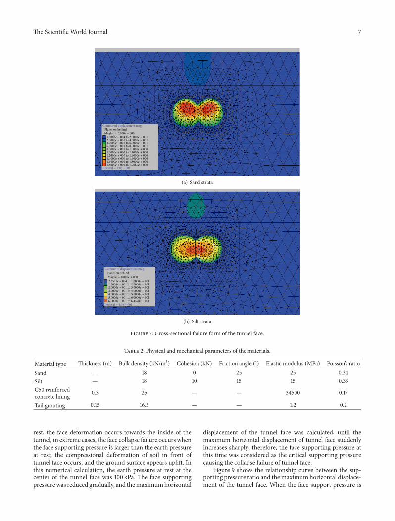
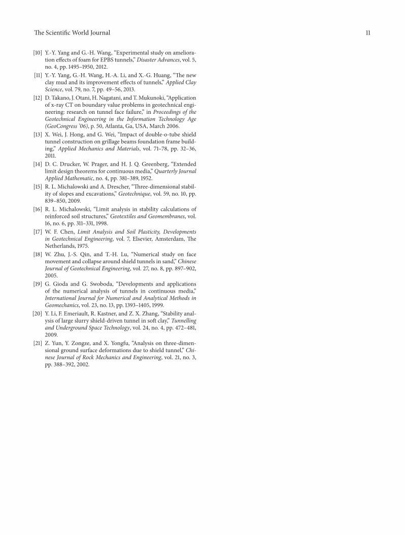

Impact Factor 173028 Days Fast Track Peer ReviewAll Subject Areas of ScienceSubmit at httpwwwtswjcom
Hindawi Publishing Corporation httpwwwhindawicom Volume 2013Hindawi Publishing Corporation httpwwwhindawicom Volume 2013
The Scientific World Journal