analysis of gyroscopic effects n rotor-disc …ethesis.nitrkl.ac.in/4686/1/211me1160.pdf · this is...
TRANSCRIPT
ANALYSIS OF GYROSCOPIC EFFECTS IN
ROTOR-DISC SYSTEMS
A thesis submitted to National Institute of Technology, Rourkela in partial fulfilment
for the degree of
Master of Technology
in
Mechanical Engineering
by
Gaurav Maurya
211ME1160
Department of Mechanical Engineering
National Institute of Technology, Rourkela
Rourkela - 769008, Odisha, India.
June - 2013
ANALYSIS OF GYROSCOPIC EFFECTS IN
ROTOR-DISC SYSTEMS
A thesis submitted to National Institute of Technology, Rourkela in partial fulfilment
for the degree of
Master of Technology
in
Mechanical Engineering
by
Gaurav Maurya
211ME1160
Under the guidance of
Dr. H. Roy
Assistant Professor
Department of Mechanical Engineering
National Institute of Technology, Rourkela
Rourkela - 769008, Odisha, India.
June - 2013
National Institute of Technology, Rourkela
CERTIFICATE
This is to certify that the thesis entitled, “Analysis of Gyroscopic Effects in Rotor-
Disc Systems”, which is submitted by Mr. Gaurav Maurya in partial fulfilment of
the requirement for the award of degree of M.Tech in Mechanical Engineering to
National Institute of Technology, Rourkela is a record of candidate’s own work
carried out by him under my supervision. The matter embodied in this thesis is
original and has not been used for the award of any other degree.
Date: 03/06/2013
Rourkela Dr. H. Roy
Assistant Professor
Mechanical Engineering Department
i
ABSTRACT
This work deals with study of dynamics of a viscoelastic rotor shaft system, where
Stability Limit of Spin Speed (SLS) and Unbalance Response amplitude (UBR) are
two indices. The Rotor Internal Damping in the system introduces rotary dissipative
forces which is tangential to the rotor orbit, well known to cause instability after
certain spin speed. There are two major problems in rotor operation, namely high
transverse vibration response at resonance and instability due to internal damping.
The gyroscopic stiffening effect has some influence on the stability. The gyroscopic
effect on the disc depends on the disc dimensions and disc positions on the rotor. The
dynamic performance of the rotor shaft system is enhanced with the help of
gyroscopic stiffening effect by optimizing the various disc parameters (viz. disc
position and disc dimension). This optimization problem can be formulated using
Linear Matrix Inequalities (LMI) technique. The LMI defines a convex constraint on
a variable which makes an optimization problem involving the minimization or
maximization of a performance function belong to the class of convex optimization
problems and these can incorporate design parameter constraints efficiently. The
unbalance response of the system can be treated with H∞ norm together with
parameterization of system matrices. The system matrices in the equation of motion
here are obtained after discretizing the continuum by beam finite element. The
constitutive relationship for the damped beam element is written by assuming a
Kelvin – Voigt model and is used to obtain the equation of motion. A numerical
example of a viscoelastic rotor is shown to demonstrate the effectiveness of the
proposed technique.
ii
ACKNOWLEDGEMENTS
I am grateful to my supervisor Dr. Haraprasad Roy, whose valuable advice, interest
and patience made this work a truly rewarding experience on so many levels. I am
also thankful to my friends and colleagues for standing by me during the past
difficult times. Particularly, I am indebted to Mr. Saurabh Chandraker for his utterly
selfless help.
As for Girish Kumar Sahu, Mallikarajan Reddy, Kamal Kumar Basumatary,
Rakesh Kumar Sonkar, Akhileshwar Singh and Abhinav Deo: You were there for me
when really needed and I am yours forever.
Gaurav Maurya

iii
NOMENCLATURE
l Length of an Element
dm Disc Mass
ir Inner Radius of an Element
or Outer Radius of an Element
s Axial Position along an Element
t Time in Seconds
T Kinetic Energy
P Potential Energy
DI Element Diametral Inertia Per Unit Length
pI Element Polar Inertia Per Unit Length
,V W Translations in Y and Z Directions
oR Position Vector of Displaced Centre of Rotation
E Young’s Modulus of Elasticity
,Y ZM M Bending Moment about Y and Z Axes
, Angles of Rotation about Y and Z Axes
Spin Angle
Spin Speed
Whirl Speed
iv
Whirl Ratio
, ,a b c
Angular Rate Components of Cross-Section about Fixed Frame
Element Mass Per Unit Length
v Viscous Damping Coefficient
,q p Displacement Vectors relative to Fixed and Rotational Frame of Reference
,Q P External Force Vectors relative to Fixed and Rotational Frame of Reference
TM Translatory Mass Matrix
RM Rotary Mass Matrix
T RM M M Total Mass Matrix of an Element
,G K Gyroscopic and Stiffness Matrices
R Orthogonal Rotation Matrix
ˆˆ ˆ, ,M G K
Transformed Mass, Gyroscopic and Stiffness Matrices
I Identity Matrix
BK Bending Stiffness Matrix
CK Skew Symmetric Circulatory Matrix
Shape Function Matrix for Displacements
Shape Function Matrix for Rotation
v
CONTENTS
Abstract i
Acknowledgements ii
Nomenclature iii
List of figures iv
1. Introduction 1
1.1 Background and Importance 1
1.2 Analysis Objective 2
1.3 Thesis Outline 4
2. Overview of Available Literature 5
2.1 History 5
2.2 Dynamics of Viscoelastic Rotor 7
2.3 Optimisation for High Performance 8
2.4 Summary 10
3. Rotor System Modelling and Optimisation 12
3.1 Equation of Motion of the System 12
3.1.1 Rigid Disc 14
3.1.2 Undamped Flexible Shaft 15
3.1.3 Damped Flexible Shaft 19
3.2 Optimisation of Disc Component 20
3.2.1 Convex Optimisation 21
3.2.2 Linear Matrix Inequalities 21
3.2.2.1 Definition 22
3.2.2.2 Formulation 23
4. Results and Discussions 28
4.1 LMI Optimisations 29
4.2 Disc Positions 31
5. Conclusions and Future Scope 34
5.1 Conclusions 34
5.2 Proposed Future Work 35
6. References 36
List of Publications 39
vi
LIST OF FIGURES
S. No. Caption Page No.
3.1 Typical Rotor Disc System Configuration 12
3.2 Cross Section Rotation Angles 13
3.3 Finite Rotor Elements and Coordinates 16
3.4 Displaced Position of the Shaft Cross-Section 16
4.1 Schematic Diagram of a Rotor System 29
4.2 Unbalance Response Bound and Optimisation of 30
4.3 Unbalance Response for Optimised and Unoptimised Disc
Dimensions
30
4.4 Decay Rate Plot for Initial and Optimised Dimensions of Disc 31
4.5 SLS plots for One Disc and Multi-Discs Rotor System 33

1
Chapter 1
INTRODUCTION
1.1 Background and importance
By the ISO definition, a rotor is a body suspended through a set of cylindrical
hinges or bearings that allow it to rotate freely about an axis fixed in space. The non-
rotating supporting structure is defined as a stator. Rotordynamics may be defined as
a specialised branch of applied mechanics dealing with the dynamics and stability of
rotating machinery. In our daily life, we frequently and unconsciously experience
rotordynamics; in the engines of aircraft jets, automobile, the pumps used in
household appliances, the drum of the washing machine, computer hard disc drives,
spindles of machine tools etc.
As the rotation speed increases, the amplitude of vibration often passes
through a maximum that is called a critical speed and corresponding zone is called as
resonance. If the amplitude of vibration at a critical speed is excessive catastrophic
failure can occur. Moreover, another phenomenon occurs quite often in rotating
machinery: instability. Rotors may develop unstable behaviour after certain spin
speed. The centrifugal force causes, in some cases, an unbounded growth of
amplitude of vibrations in time. The ranges of rotation speeds in which self-
excitation occurs are called the instability fields. These so-called self-excited
vibrations can result in catastrophic failure.
This is why accurate modelling of the rotordynamic behaviour is crucial in
the design of rotating machinery in order to improve product reliability, to increase
process efficiency to prolong machinery life and enable safe operation.
Developments in computer technology and numerical methods such as Finite
Element Method (FEM) have made more accurate and detailed rotordynamic
analysis possible. Nowadays, extensive studies are available in the literature about
the modelling and testing of the effects of different physical phenomena on rotating
machineries.
2
Rotordynamics analysis date backs to the second half of the nineteenth
century because of the necessity of including the rotation speed into dynamic
analysis as the rotational speed of many machine elements started to increase. Many
scientists tried to provide a theoretical explanation of the rotordynamic behaviour. In
1919, Jeffcott introduced his paper about the dynamic analysis of rotors and
presented a simple model that consists of a point mass attached to a massless shaft.
Even though the Jeffcott rotor is much simpler then the real-life rotors, it still
provides insight into important phenomena in rotordynamics. But for precise analysis
of complex machines such as steam and gas turbines, compressors, pumps, etc., more
advanced models are required.
1.2 Analysis Objective
By the turn of 20th
century, turbine manufacturers had started to design and
operate rotors supercritically. That was only after DeLaval’s experiment
demonstration of the safely sustained supercritical operation of a steam turbine. His
experiment refuted Rankine’s hypothesis that rotors, modelled with no Coriolis
component, cannot be stable if operated over a speed above the critical one.
No sooner did turbine manufacturers start operating supercritical rotors than
they encountered severe vibrations that were at first related to imbalance. The
industry was bewildered by the successful supercritical operations of some units but
not others of similar constructions. A few researchers hypothesised on the possibility
of Rotor Internal Damping (RID) or Material Damping of rotor system being the
cause but took it no further until General Electrics (GE) severe problems with their
blast furnaces’ compressors. In 1924, Kimball came to then apparently illogical
reasoning that RID caused such instability as it induced a follower force that is
tangential to the rotor’s orbit, acts in its direction of precession and increases in
magnitude with speed of the rotor. He then argued that this force could overcome the
stabilising external damping forces at a certain supercritical onset speed, thereby
rendering the rotor unstable.
3
RID or material damping was the first recognised cause of instability and oil-
whip followed shortly after. The material damping (RID) in the rotor shaft introduces
rotary dissipative force which is tangential to the rotor orbit, well known to cause
instability after certain spin speed. Thus high speed rotor operation suffers from two
problems viz. 1) high transverse response due to resonance and 2) instability of the
rotor-shaft system over a spin-speed. Both phenomena occur due to material inherent
properties and set limitations on operating speed of a rotor. By using light weight and
strong rotor, the rotor operating speed can be enhanced. These two parameters have
some practical limitations. In other words, the gyroscopic stiffening effect has some
influence on the stability. The gyroscopic effect on the disc depends on the disc
dimensions and disc position on the rotor. Thus, the proper positioning of the discs
and optimised dimensions may ensure high speeds and maximum stability.
Optimization of a structural design within the constraints imposed by machine
functionality and physical feasibility can minimize the circulatory effects,
transmitted noise and vibration, reduce machine wear, and reduce the likelihood of
premature failure. A number of researchers have developed numerical methods for
optimizing the structural design of a rotor system subject to dynamic performance
constraints, with particular focus on critical speed locations.
This work has used finite element method as the basis for assessing vibration
behaviour. It reports on a different approach to structural design optimization, where
objectives for dynamic performance are formulated as a set of linear matrix
inequalities (LMIs) that directly incorporate the design variables to be optimized.
Linear matrix inequalities are being increasingly used in the analysis and control of
dynamic systems as there are fast and efficient numerical algorithms to solve them.
Multiple LMIs relating to performance, stability, or parameter constraints can be
combined to form a single LMI, which can be solved using the same generic-
algorithms. This flexibility means that LMIs can be used to solve a wide range of
optimization problems and create design specifications concerning vibration
4
amplitudes, stability, critical speeds, modal damping levels, and parameter
constraints. Moreover, multiple criteria can be combined without destroying the
underlying mathematical form of the optimization problem or the algorithm required
to solve it. Another advantage of the LMI formulation is that it can deal effectively
with uncertain or time varying parameters, particularly those arising from speed
dependent dynamics.
1.3 Thesis Outline
Chapter 2 gives a brief history of rotordynamics which is followed by a
brief overview of the development of dynamics of rotor shaft systems. It discusses
the various rotor models and stability study of systems under various internal and
external effects. Then, an overview of various optimisation techniques used in recent
past and present. Chapter 3 develops the equation of motion for a viscously damped
rotor system. It discusses the finite element modelling of the system which is later
used in the optimisation of disc parameters to ensure high stability for a specific
configuration of the system. It discusses the Linear Matrix Inequalities (LMIs)
technique for optimisation of disc dimensions. Chapter 4 discusses design of a disc
for a rotor disc system and a theoretical method to obtain proper disc positions
ensuring high working stability for the system. Finally, the conclusions, future scope
of the work and references are presented in chapters 5and 6, respectively.
5
Chapter 2
OVERVIEW OF AVAILABLE LITERATURE
2.1 History
Rotordynamic studies related to technological applications date back to the
second half of the nineteenth century, when the increase of the rotational speed of
many machine elements made it necessary to include rotation into the analysis of
their dynamic behaviour. However, the dynamics of rotating systems, as far as rigid
rotors are concerned, was already well understood and the problem of the behaviour
of the spinning top had been successfully dealt with by several mathematicians and
theoretical mechanicists.
The paper which is considered to be the first paper fully devoted to
Rotordynamics is, on the centrifugal force on rotating shafts, published in The
Engineer by Rankine [29]. It correctly states that a flexible rotating system has a
speed, defined by the author as critical speed, at which very large vibration
amplitudes are encountered. However, the author incorrectly predicts that stable
running above the critical speed is impossible.
Earlier attempts to build turbines, mainly steam turbines, at the end of
nineteenth century led to rotational speeds far higher than those common in other
fields of mechanical engineering. At these speeds, some peculiar dynamic problems
are usually encountered and must be dealt with to produce a successful design. De
Laval had to solve the problem correctly understanding the behaviour of a rotor
running at speeds in excess of critical speed, i.e., in supercritical conditions, while
designing his famous cream separator and then his steam turbine.
A theoretical explanation of supercritical running was supplied first by Foppl
[21], Belluzzo [9], Stodola [6] and Jeffcott [25] in his famous paper of 1919.
Although the first turbine rotors were very simple and could be dealt with by using
simple models, of the type now widely known as Jeffcott rotor, more complex
machines required a more detailed modelling. Actually, although a simplified
6
approach like the above-mentioned Jeffcott rotor can explain qualitatively many
important features of real-life rotors, the most important being self-centring in
supercritical conditions and the different roles of the damping of the rotor and of the
nonrotating parts of the machine, it fails to explain other features, such as the
dependence of the natural frequencies on the rotational speed. Above all, the simple
Jeffcott rotor does not allow us to obtain a precise quantitative analysis of the
dynamic behaviour of complex systems, e.g., those encountered in gas or steam
turbines, compressors, pumps, and many other types of machines.
To cope with the increasing complexity of rotating systems, graphical
computation schemes were devised. The availability of electromechanical calculators
allowed us to develop tabular computational procedures, mainly based on the
transfer matrices approach, which eventually substituted graphical computations. In
particular, Holzer’s method for the torsional vibrations of shafts and the Myklestadt-
Prohl method for the computation of the critical speeds of turbine rotors were, and
still are, widely used. These methods were immediately automatized when digital
computers became available.
The wide diffusion of the finite element method (FEM) deeply influenced
also the field of rotordynamics. Strictly speaking, usual general purpose FEM codes
cannot be used for rotordynamic analysis owing to the lack of consideration of
gyroscopic effects. It is true that a gyroscopic matrix can be forced in the
conventional formulation and that several manufacturers use commercial FEM codes
to perform rotordynamic analysis, but the rotordynamic field is one of these
applications in which purposely written, specialized FEM codes can give their best.
Through FEM modelling, it is possible to study the dynamic behaviour of machines
containing high-speed rotors in greater detail and consequently to obtain quantitative
predictions with an unprecedented degree of accuracy.
7
2.2 Dynamics of a Viscoelastic Rotor
Extensive studies are available in the literature about the modelling and
testing of the effects of different physical phenomena on rotating machineries.
Nelson and McVaugh [26] presented a procedure for dynamic modelling of rotor
bearing systems which consisted of rigid discs, distributed parameter finite rotor
elements, and discrete bearings. They presented their formulation in both a fixed and
rotating frame of reference. They developed a finite element model including the
effects of rotary inertia, gyroscopic moments, and axial load. The model was based
on Euler-Bernoulli beam theory. Later, Zorzi and Nelson [34] extrapolated the same
model for rotor with internal damping. Their model consisted of both viscous as well
as hysteretic damping. They demonstrated that the material damping in the rotor
shaft introduces rotary dissipative forces which are tangential to the rotor orbit, well
known to cause instability after certain spin speed. Both forms of internal damping
destabilise the rotor system and induce non-synchronous forward precession. This
model is one of the best models that explain effects of internal damping and spin
speed on the dynamic behaviour of the system in its full entirety.
Correct quantitative prediction is particularly important as the trends of
technology toward higher power density, lower weight, and faster machines tend to
make worse all problems linked with the dynamic behaviour of rotating machinery.
Higher speeds are often a goal in themselves, like in machine tools or other
production machines in which spinning faster means directly increasing productivity.
In applications related to power generation or utilization, a faster machine can
develop or convert more power manipulating the same torque. As torque is usually
the critical factor in dimensioning machine elements (shaft cross section, size of the
conductors in electrical machinery, etc.), increasing the speed allows us to make
power devices lighter. The use of materials able to withstand higher stresses allows
us to reduce the mass and the size of machinery, but stronger materials (e.g., high
strength steels or light alloys) are usually not stiffer and then these lighter machines

8
are more compliant and more prone to vibrate and thus, causing them to become
unstable.
Researchers like Gunter [23], Dutt and Nakra [19], Genta [3], and Lalanne
and Ferraris [4], studied the stability of the system with internal damping. They
obtained the results in form of Campbell diagrams and Decay Rate plots. Unbalance
response and the threshold spin speed called Stability Limit of Spin Speed were
taken as indices of stability. Bulatovic [11-14] performed a great deal of
mathematical operations and obtained many theorems, necessary and sufficient
conditions for stability of both conservative and non-conservative systems including
gyroscopic effect. Gyroscopic effects enhance stability in a damped rotor which has
been discussed by M. A. Kandil in his Doctoral Thesis [7].
With the invention of composite materials and their advantages over
conventional material, their utilisation became frequent and now most of the
machines working over supercritical speeds are made using composite material for
their long lives. Accordingly, researchers were not only restricted to a mono-material
system but they started analysing multi-material systems. Panda and Dutt [27-28]
attempted to predict the frequency dependent material properties of polymeric
supports for obtaining optimum performance of rotor-shaft systems i.e. to achieve
simultaneously lowest synchronous unbalanced response amplitude as well as
highest stability limit of the spin speed. Dutt and Roy [20] studied the stability of
polymeric rotor systems, where the equation of motion in the finite element
formulation is developed by using the operator based constitutive relationship.
2.3 Optimisation for High Performance
A number of researchers have developed numerical methods for optimizing
the structural design of a rotor system subject to dynamic performance constraints, in
order to obtain high stability with system running at high speeds. Early work by
Bhavikatti [10] and Ranta [30] and co-researchers tackled the problem of minimizing
the weight of a rotor subject to constraints on stresses and eigenvalues of the system,
9
respectively. The design variables considered in these studies included the inner
radius of hollow rotor sections, the positions of bearings and rigid disc elements, and
the bearing stiffnesses. Chen and Wang [16] have tackled similar design
optimization problems but used an iterative method to manipulate the eigenvalues of
rotor vibration modes. In their study the outer diameter of rotor sections was varied,
together with bearing stiffness and damping coefficients. Jafari et al. [24] aimed at
finding an optimal disc profiles for minimum weight design using the Karush-Kunh-
Tucker (KKT) method as classical optimisation method, Simulated Annealing (SA),
and Particle Swarm Optimization (PSO) as two modern optimisation methods. They
used the von Mises failure criterion of optimum disc as an inequality constraint to
make sure that the rotating disc does not fail. Their result showed that KKT method
gives a profile that is slightly less weight while the implementation of PSO and SA is
easier and provide flexibility as compared to KKT. A study by Choi and Yang [17]
considered using immune genetic algorithms to minimize rotor weight and
transmitted bearing forces. Stocki et al. [32] found that the commonly observed
nowadays tendency of weight minimization of rotor-shafts of the rotating machinery
leads to decrease of shaft bending rigidity making a risk of dangerous stress
concentrations and rubbing effects more probable. They aimed at determination of
optimal balance between reducing the rotor shaft weight and assuring its admissible
bending flexibility. The random nature of residual unbalances of the rotor shaft as
well as randomness of journal bearing stiffness have been taken into account in the
frame work of robust design optimization. Such a formulation of optimization
problem leads to the optimum design that combines an acceptable structural weight
with the robustness with respect to uncertainties of residual unbalance – the main
source of bending vibrations causing the rubbing effects. They applied robust
optimization technique based on Latin Hypercubes in scatter analysis of vibration
response. The proposed method has been applied for the optimization of the typical
single-span rotor shaft of the 8-stage centrifugal compressor. Further work by Shiau
10
et al. [31] involved a two-stage optimization with a genetic algorithm to find initial
values of design variables for further optimization. In their study, various parameter
constraints were incorporated in an objective function using a Lagrange multiplier
method.
Cole et al. [18] considered optimization of rotor system design using stability
and vibration response criteria. Their study included the effects of certain design
changes that can be parameterized in a rotor dynamic model through their influence
on the system matrices obtained by finite element modelling. They derived a suitable
vibration response measure by considering an unknown and axial distribution of
unbalanced components having bounded magnitude. They showed that the worst
case unbalanced response can be given by an absolute row sum norm of the system
frequency response matrix. They minimized this norm through the formulation of
linear matrix inequalities (LMIs) that were incorporated with design parameter
constraints and the stability criteria. A case study was presented where the method
was applied for the optimal selection of bearing support stiffness and damping levels
to minimize the worst case vibration of a flexible rotor over a finite speed range. The
LMIs are capable of dealing with non-linear systems and they can include design
constraints directly. The LMI defines a convex constraint on a variable which makes
an optimization problem involving the minimization or maximization of a
performance function belong to the class of convex optimization problems and these
can incorporate design parameter constraints efficiently. Multiple LMIs relating to
performance, stability, or parameter constraints can be combined to form a single
LMI, which can be solved using the same usual algorithms. This flexibility means
that LMIs can be used to solve a wide range of optimization problems [1].
2.4 Summary
As can be seen from the literature survey a great deal of work has been done
in analysing a rotating system both undamped and damped. Researchers established
the stability of the system and recognised various factors affecting stability of a
11
particular rotating system. Optimisation techniques have been utilised in order to
improve dynamic performance of different configuration of systems. Rotor internal
damping which is one of the main factors causing instability can be countered easily
if a favourable gyroscopic effect can be maintained in the system. This gyroscopic
effect will aid in stability and depends upon various factors such as dimensions of
rotor system and positions of mountings such as gears, pulley, wheels, etc.
Researchers have used many different techniques like Genetic Algorithm (GA),
Particle Swarm Optimisation (PSO), etc., to optimise rotor parameters to obtain
favourable working. But these optimisation techniques are cumbersome as they
require obtaining both local and global minima and maxima, whereas Linear Matrix
Inequalities (LMI) technique can efficiently handle non-linear systems. Many
optimisation problems in control, identification and signal processing can be
formulated (or reformulated) using Linear Matrix Inequalities. Since an LMI defines
a convex constraint on the variable, the optimisation problems involving the
minimisation or maximisation of a performance function belong to the class of
convex optimisation problems. In Convex Optimisation, the local minima and global
minima are same and in case of strictly convex function the minimum value of a
function is unique. Thus, if the system can be reduced or formulated to a system of
LMIs defining strict convex constraint on the variables, then, the problem remains to
find the global optimum. The motivation here was the absentia of such methods
which can be applied directly to systems to be controlled. The sole purpose of this
piece of work is to represent the factors affecting stability of a system, optimisation
of parameters to ensure high stability and a presentation of a less known technique of
optimisation for efficient optimisation.
This work includes a theoretical technique to obtain disc positions where the
system would be more stable and also, includes optimisation of disc dimensions
using LMI technique for ensuring high stability.
12
Chapter 3
ROTOR SYSTEM MODELLING AND OPTIMISATION
The foundation of analysis is laid here. This chapter includes the Finite
Element Modelling of a rotor system followed by optimisation of various disc
parameters ensuring high stability of the system.
3.1 Equation of Motion of the System
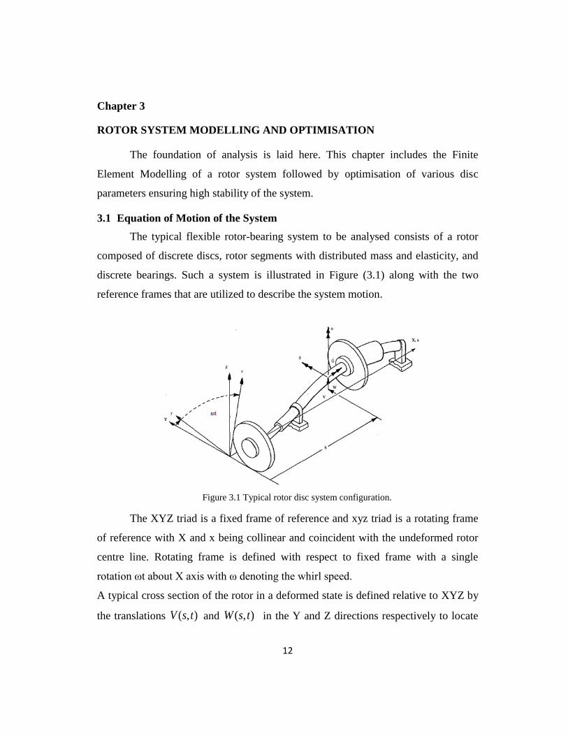
The typical flexible rotor-bearing system to be analysed consists of a rotor
composed of discrete discs, rotor segments with distributed mass and elasticity, and
discrete bearings. Such a system is illustrated in Figure (3.1) along with the two
reference frames that are utilized to describe the system motion.
Figure 3.1 Typical rotor disc system configuration.
The XYZ triad is a fixed frame of reference and xyz triad is a rotating frame
of reference with X and x being collinear and coincident with the undeformed rotor
centre line. Rotating frame is defined with respect to fixed frame with a single
rotation ωt about X axis with ω denoting the whirl speed.
A typical cross section of the rotor in a deformed state is defined relative to XYZ by
the translations ( , )V s t and ( , )W s t in the Y and Z directions respectively to locate
13
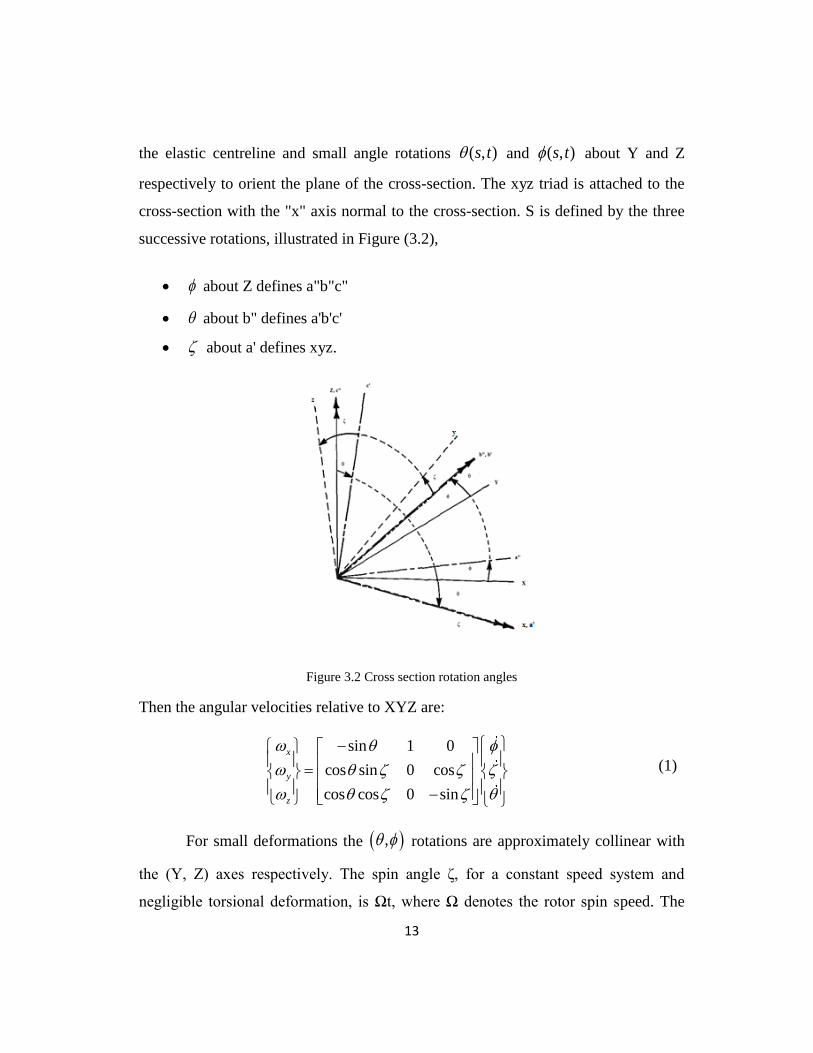
the elastic centreline and small angle rotations ( , )s t and ( , )s t about Y and Z
respectively to orient the plane of the cross-section. The xyz triad is attached to the
cross-section with the "x" axis normal to the cross-section. S is defined by the three
successive rotations, illustrated in Figure (3.2),
about Z defines a"b"c"
about b" defines a'b'c'
about a' defines xyz.
Figure 3.2 Cross section rotation angles
Then the angular velocities relative to XYZ are:
sin 1 0
cos sin 0 cos
cos cos 0 sin
x
y
z
(1)
For small deformations the , rotations are approximately collinear with
the (Y, Z) axes respectively. The spin angle ζ, for a constant speed system and
negligible torsional deformation, is Ωt, where Ω denotes the rotor spin speed. The
14
displacements , , ,V W of a typical cross-section relative to XYZ are transformed
to corresponding displacements , , ,v w relative to xyz by the orthogonal
transformation.
q R p (2)
with
cos sin 0 0
sin cos 0 0, &
0 0 cos sin
0 0 sin cos
V v t t
W w t tq p R
t t
t t
Their time first and second time derivative can be given as
2 2
q S p R p
q R p p S p
(3)
with
sin cos 0 0
cos sin 0 01
0 0 sin cos
0 0 cos sin
t t
t tS R
t t
t t
Here the rotor-bearing system is considered to comprise a set of
interconnecting components consisting of rigid discs, rotor segments with distributed
mass and elasticity, and linear bearings. In this section the rigid disc equation of
motion is developed using a Lagrangian formulation. The finite rotor element
equation of motion is developed in an analogous manner by specifying spatial shape
functions and then treating the rotor element as an integration of an infinite set of
differential discs. The bearing equations are not developed and only the linear forms
of the equations are utilized in this work.
3.1.1 Rigid Disc
The kinetic energy of a typical rigid disc with mass centre coincident with the
elastic rotor centreline is given by the expression

15
0 001 1
0 002 2
0 0
T
T x d x
d
d y d y
d
z p z
ImV V
T ImW W
I
(4)
With the aid of Eq. (3), Eq. (4) becomes
0 01 1
0 02 2
TT
d d
d p
d d
m IV VT I
m IW W
(5)
The Lagrangian equation of motion of the rigid disc using above equation
and the constant spin speed restrictions, t , is
d d d d d d
T RM M q G q Q (6)
The preceding equation is the equation of motion of the rigid disc referred to the
fixed frame of reference with the forcing term including mass unbalance,
interconnection forces, and other external disc effects on the disc.
By using Eqs. (2-3) and pre-multiplying by T
R , Eq. (6) transforms to
2 ˆˆ ˆ2d d d d d d d d d d d d
T R T R T RM M p M M G p M M G p P (7)
For the case of thin disc ( 2P dI I ), Eq. (7) becomes
2ˆ2 1 1 2d d d d d d d d d d
T R T T RM M p M G p M M p P (8)
The Eq. (8) is the equation of motion of a rigid disc referred to rotating frame with
whirl ratio .
3.1.2 Undamped Flexible Shaft
A typical finite rotor element is illustrated in Figure (3.3). The coordinates
1 2 3 8, , ,.......,q q q q are the time dependent end point displacements (translations and
rotations).
16
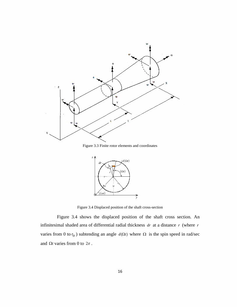
Figure 3.3 Finite rotor elements and coordinates
Figure 3.4 Displaced position of the shaft cross-section
Figure 3.4 shows the displaced position of the shaft cross section.
An
infinitesimal shaded area of differential radial thickness dr at a distance r (where r
varies from 0 to or ) subtending an angle ( )d t where is the spin speed in rad/sec
and t varies from 0 to 2 .
v
wRo
z
t
t
y
r0
d t
r
dr
17
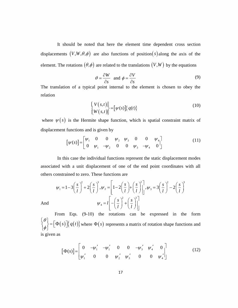
It should be noted that here the element time dependent cross section
displacements , , ,V W are also functions of position s along the axis of the
element. The rotations , are related to the translations ,V W by the equations
W
s
and
V
s
(9)
The translation of a typical point internal to the element is chosen to obey the
relation
,( ) ( )
,
V s ts q t
W s t
(10)
where s is the Hermite shape function, which is spatial constraint matrix of
displacement functions and is given by
1 2 3 4
1 2 3 4
0 0 0 0( )
0 0 0 0s
(11)
In this case the individual functions represent the static displacement modes
associated with a unit displacement of one of the end point coordinates with all
others constrained to zero. These functions are
2 3
1 1 3 2s s
l l
,
2
2 1 2s s
l l
,
2 3
3 3 2s s
l l
And
2 3
4
s sl
l l
From Eqs. (9-10) the rotations can be expressed in the form
s q t
where s represents a matrix of rotation shape functions and
is given as
1 1 3 4
1 2 3 4
0 0 0 0( )
0 0 0 0s
(12)
18
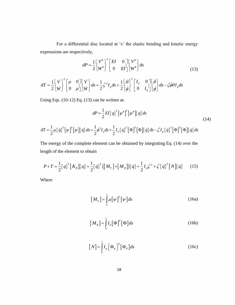
For a differential disc located at ‘s’ the elastic bending and kinetic energy
expressions are respectively,
01
02
TV EI V
dP dsW EI W
2001 1 1
002 2 2
TT
d
p p
d
IV VdT ds I ds ds I ds
IW W
(13)
Using Eqs. (10-12) Eq. (13) can be written as
1
2
TTdP EI q q ds
21 1 1
2 2 2
T T TT T T
p d pdT q q ds I ds I q q ds I q q ds
(14)
The energy of the complete element can be obtained by integrating Eq. (14) over the
length of the element to obtain
21 1 1
2 2 2
T T T
B T R pP T q K q q M M q I q N q (15)
Where
0
lT
TM ds (16a)
0
lT
R dM I ds (16b)
0
lT
pN I ds (16c)

19
0
lT
BK EI ds (16d)
T
G N N (16e)
Then, the Lagrangian equation of motion for the finite rotor element and the constant
spin speed restriction, t , is
T R BM M q G q K q Q (17)
3.1.3 Damped Flexible Shaft
To extend this model to a damped rotor, internal damping is assumed to be
of viscous in nature (Zorzi and Nelson [34]) and as such the stress and strain
relationship can be given as:
vE 2
2
( , )cos oR x t
r tx
(18a)
2 2
2 2sin coso oR R
r t r tx t x
(18b)
Where E and v are modulus of elasticity and viscous damping coefficient,
respectively.
It is noteworthy that some insight into the characteristics of internal damping
can be gained from inspection of Eqs. (18a) and (18b). From Eq. (18b), it is apparent
that if the system is in a synchronous precessional state, , and if the orbit is
circular, 2 2 0ot R x , then the viscous damping component can offer no
alteration of the axial stress Eq. (18). Thus, for circular synchronous orbits, the
internal viscous damping component cannot produce any out of phase loading to

20
reduce the critical speed orbit. Therefore, either external damping or anisotropic
bearings are beneficial here in limiting excursions when traversing critical speeds.
The bending moments at any instant about X and Y-axes are expressed as
o
2 o
0 0
2
0 0
cos ( )
sin ( )
r
Z
r
Y
M V r t rdrd t
M W r t rdrd t
(19)
Substituting values from Eq. (18) and performing required integration, the equations
for bending moment becomes
1 0
1 0
v vZ
v vY
M V VEI EI
M W W
(20)
Defining the differential bending energy and dissipation function as:
11
12
01
02
v
v
v
v
VdP EI ds
W
VdD EI ds
W
(21)
From Eqs. (20-21)
1
2
2
TT
TTv
dP EI q q ds
dD EI q q ds
(22)
Combining this with earlier equations giving the kinetic energy of the system,
the Lagrangian equations of motion can be established for damped rotor finite
element as
T R v B B v cM M q K G q K K q Q t (23)
21
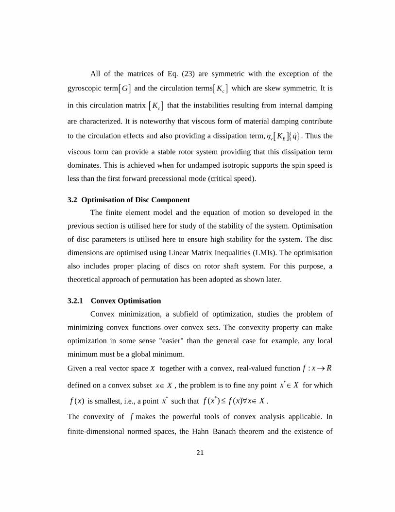
All of the matrices of Eq. (23) are symmetric with the exception of the
gyroscopic term G and the circulation terms cK which are skew symmetric. It is
in this circulation matrix cK that the instabilities resulting from internal damping
are characterized. It is noteworthy that viscous form of material damping contribute
to the circulation effects and also providing a dissipation term, v BK q . Thus the
viscous form can provide a stable rotor system providing that this dissipation term
dominates. This is achieved when for undamped isotropic supports the spin speed is
less than the first forward precessional mode (critical speed).
3.2 Optimisation of Disc Component
The finite element model and the equation of motion so developed in the
previous section is utilised here for study of the stability of the system. Optimisation
of disc parameters is utilised here to ensure high stability for the system. The disc
dimensions are optimised using Linear Matrix Inequalities (LMIs). The optimisation
also includes proper placing of discs on rotor shaft system. For this purpose, a
theoretical approach of permutation has been adopted as shown later.
3.2.1 Convex Optimisation
Convex minimization, a subfield of optimization, studies the problem of
minimizing convex functions over convex sets. The convexity property can make
optimization in some sense "easier" than the general case for example, any local
minimum must be a global minimum.
Given a real vector space X together with a convex, real-valued function :f x R
defined on a convex subset x X , the problem is to fine any point *x X for which
( )f x is smallest, i.e., a point *x such that
*( ) ( )f x f x x X .
The convexity of f makes the powerful tools of convex analysis applicable. In
finite-dimensional normed spaces, the Hahn–Banach theorem and the existence of
22
sub gradients lead to a particularly satisfying theory of necessary and sufficient
conditions for optimality, a duality theory generalizing that for linear programming,
and effective computational methods.
Convex minimization has applications in a wide range of disciplines, such
as automatic control systems, estimation and signal processing, communications and
networks, electronic circuit design, data analysis and modelling, statistics (optimal
design), and finance. With recent improvements in computing and in optimization
theory, convex minimization is nearly as straightforward as linear programming.
Many optimization problems can be reformulated as convex minimization problems.
For example, the problem of maximizing a concave function can be re-formulated
equivalently as a problem of minimizing the function, which is convex.
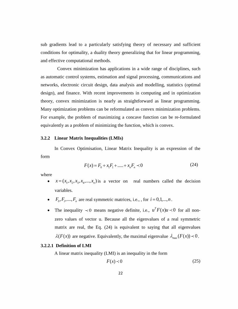
3.2.2 Linear Matrix Inequalities (LMIs)
In Convex Optimisation, Linear Matrix Inequality is an expression of the
form
0 1 1( ) ..... 0n nF x F x F x F (24)
where
1 2 3 4( , , , ,..., )nx x x x x x is a vector on real numbers called the decision
variables.
0 1, ,...., nF F F are real symmetric matrices, i.e., , for 0,1,...,i n .
The inequality 0 means negative definite, i.e., ( ) 0Tu F x u for all non-
zero values of vector u. Because all the eigenvalues of a real symmetric
matrix are real, the Eq. (24) is equivalent to saying that all eigenvalues
( ( ))F x are negative. Equivalently, the maximal eigenvalue max ( ( )) 0F x .
3.2.2.1 Definition of LMI
A linear matrix inequality (LMI) is an inequality in the form
( ) 0F x (25)
23
Where ( )F x is an affine function mapping in a finite dimensional vector space x to
either Hermitian or Symmetric vector space.
In most control applications, LMI’s arise as functions of matrix variables rather than
scalar valued decision variables. This means that we consider inequalities of the form
Eq. (25) where 1 2
1
m mx R is the set of real matrices of dimension 1 2m m .
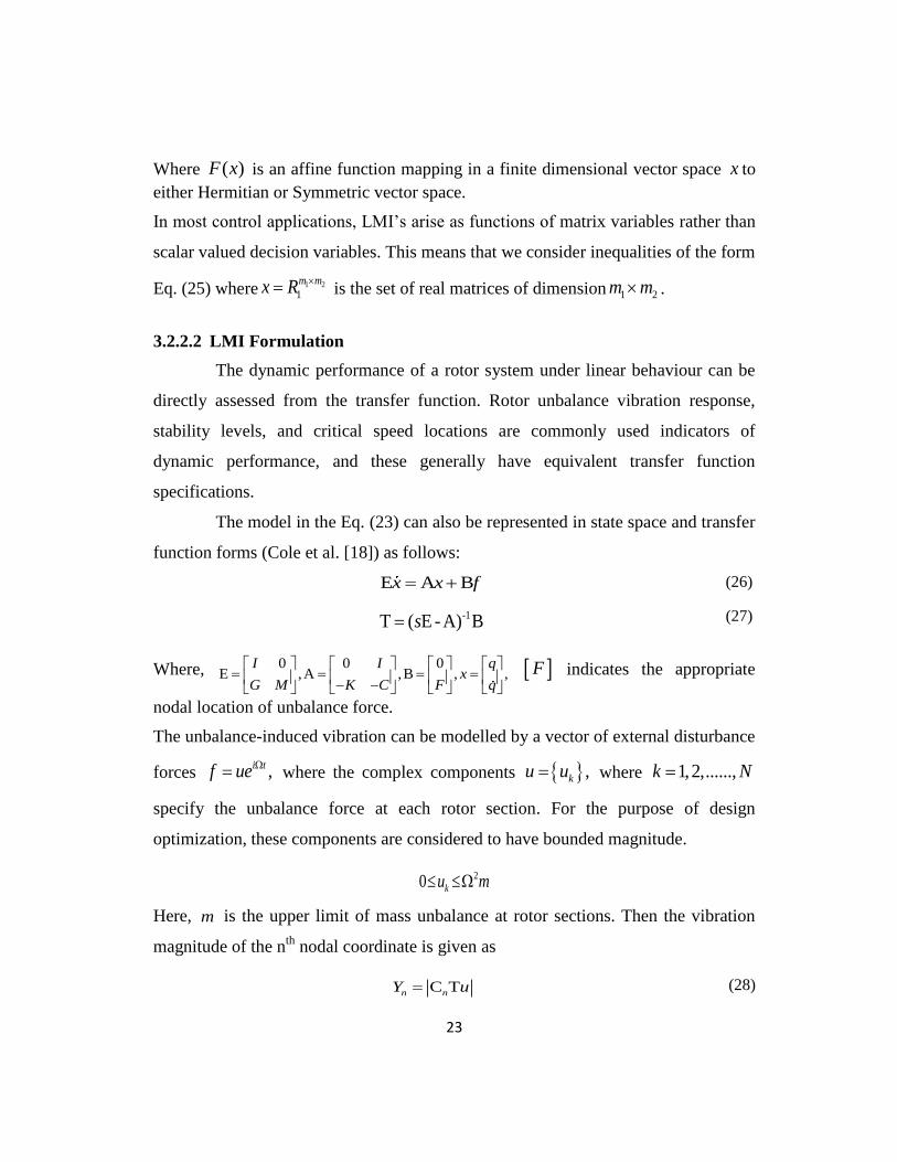
3.2.2.2 LMI Formulation
The dynamic performance of a rotor system under linear behaviour can be
directly assessed from the transfer function. Rotor unbalance vibration response,
stability levels, and critical speed locations are commonly used indicators of
dynamic performance, and these generally have equivalent transfer function
specifications.
The model in the Eq. (23) can also be represented in state space and transfer
function forms (Cole et al. [18]) as follows:
E A Bx x f (26)
-1T ( E - A) Bs (27)
Where, 0 0 0E ,A ,B , ,
I I qx
G M K C F q
F indicates the appropriate
nodal location of unbalance force.
The unbalance-induced vibration can be modelled by a vector of external disturbance
forces ,i tf ue where the complex components ,ku u where 1,2,......,k N
specify the unbalance force at each rotor section. For the purpose of design
optimization, these components are considered to have bounded magnitude.
20 ku m
Here, m is the upper limit of mass unbalance at rotor sections. Then the vibration
magnitude of the nth
nodal coordinate is given as
C Tn nY u (28)

24
Where Cn selects the appropriate rows of T .
It can also be written as
1 1
N N
n k k k k
k k
Y g u g u
(29)
Where,
1 2T ,T ,......,T C Tn ng
The worst case occurs when the maximum value of ku is reached which is given as
2
ku m .
Therefore, the worst case performance for a system can be given as
2
1
N
n k k
k
Y g m
(30)
Thus, the worst-case vibration amplitude at a particular machine location is
given by the absolute row-sum of the corresponding frequency response matrix ' 'g
with each input scaled by 2m . For the purpose of system design, a constraint can
be specified in the form ,Y f giving, for all values of and is the scaling
factor.
2
1
/N
k k
k
g m f
(31)
Where the bounding function f may be chosen to reflect any design
constraints concerning critical speed locations and running speed ranges. The
bounding function 2f can be treated using a stable transfer functionW . With
a tight bound min , it follows that there exists wc for which
min
1
N
k k
k
g m
(32)
The objective of the design optimization is to minimize . The requirement
of stable operation of the rotor system can be further specified in terms of quadratic
stability of the system. To treat the row sum norm specification of Eq. (31), consider

25
first the more commonly used L norm-bound on the system with the input scaled by
kd .
2
21
| |Nk
k k
g
d
(33)
If 1k kd m and the above condition is satisfied with min , it then followed that
min min minN
Consequently, the L norm-bound can provide a loose bound on the row-
sum norm.
In an effort to obtain a much tighter bound during an optimisation procedure
a direct calculation of the worst-case vibration components k kt g can be used to
select / ,k k kd t m the input scaling factor. The vibration response criteria of Eq.
(29) can then be tackled with an iterative design optimisation procedure by
minimising the bound in Eq. (33) at each design iteration and then updating kt . If
after a number of design iterations
2 2
1 1
( ) ( )N Nk k k wc k
k kk k
g j m g j m
t t
(34)
Then it follows that
2
min
1
( )Nk wc k
k k
g j m
t
(35)
And thus min min
The time domain equivalent of Eq. (33), is the peak RMS bound
2 2
0 0
D
T T
T
ny dt f fdt (36)
26
For all ( ),f t where 1 2 3D , , ,......, ,kdiag d d d d
is a diagonal scaling matrix.
Quadratic stability of the system can be proved by the existence of a Lyapunov
function of the form.
V( ) ( ) P ( )Tt x t x t (37)
Where P is a positive definite matrix such that V 0 for all possible state variables
with 0 ,f from Eq. (26), defining 1 1Q E PE 0
T
V A B QE E Q A BT T Tx f x x x f (38)
Combining Eqs. (36-37) we get 2 2V f D f 0T
ny (39)
With ,n ny C x the above equation becomes
2A B QE E Q A B C C f D f 0T T T T T T
n nx f x x x f x x (40)
Therefore,
2
A QE E QA C C E QB0
ff B QE D
T T T T T
n n
T T
xx
(41)
For all f 0T
T Tx Thus, the design criterion is equivalent to the existence of a
symmetric matrix Q 0 for which the following symmetric matrix is negative
definite:
2
A QE E QA C C E QB0
B QE D
T T T T
n n
T
(42)
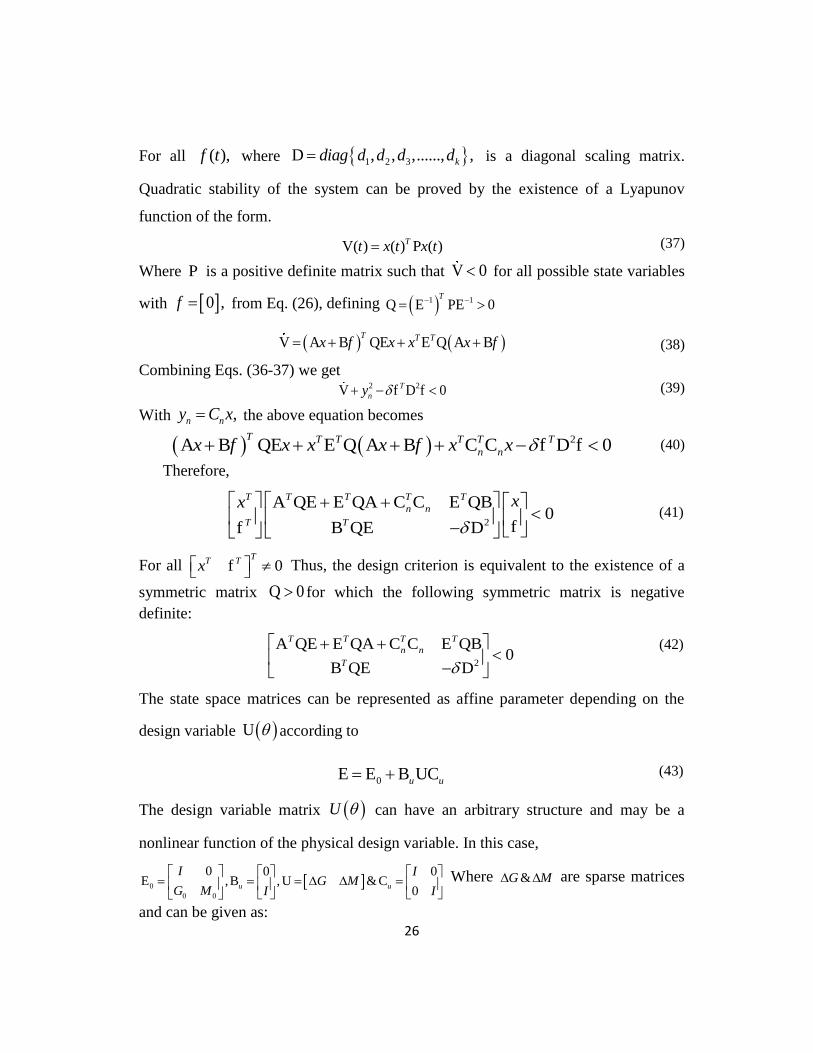
The state space matrices can be represented as affine parameter depending on the
design variable U according to
0E E B UCu u (43)
The design variable matrix U can have an arbitrary structure and may be a
nonlinear function of the physical design variable. In this case,
0
0 0
0 0 0E ,B , U &C
0u u
I IG M
G M I I
Where &G M are sparse matrices
and can be given as:
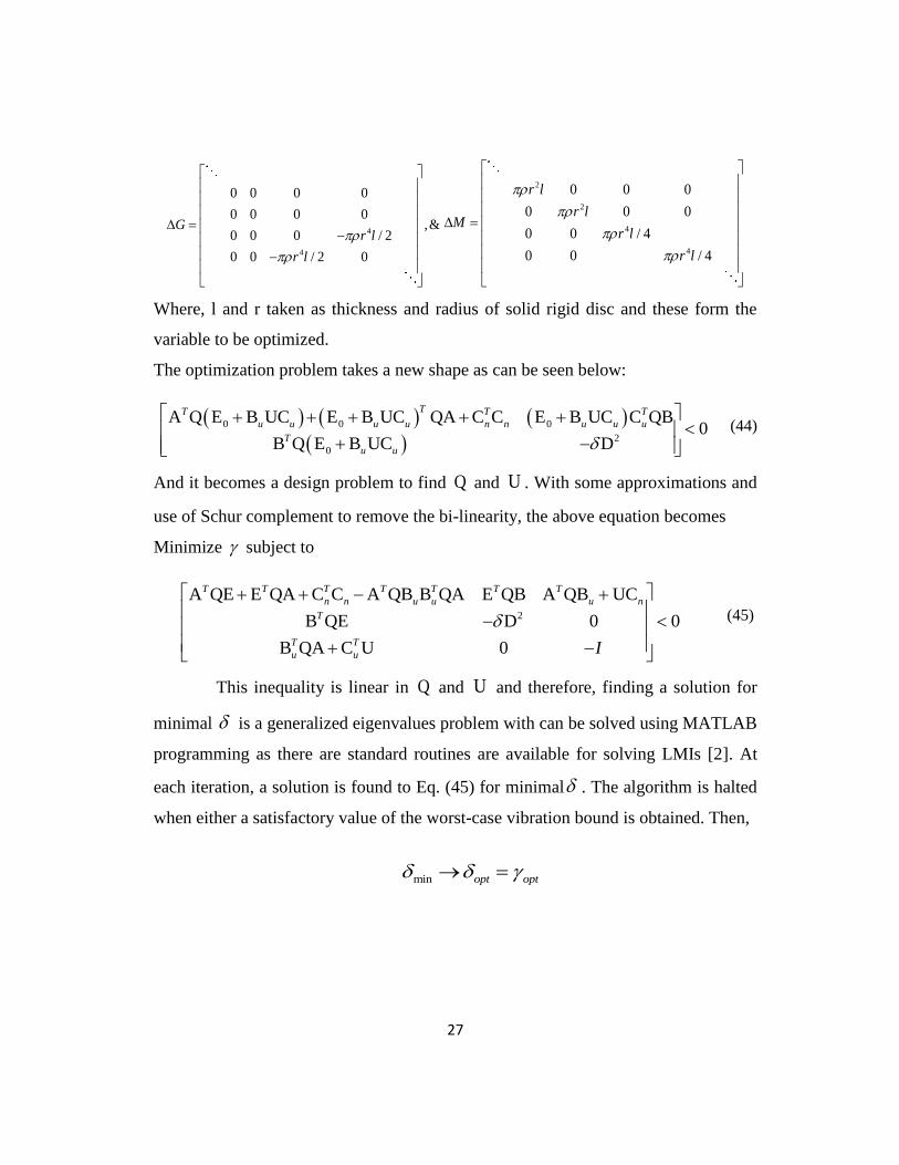
27
4
4
0 0 0 0
0 0 0 0,&
0 0 0 / 2
0 0 / 2 0
Gr l
r l
2
2
4
4
0 0 0
0 0 0
0 0 / 4
0 0 / 4
r l
r lM
r l
r l
Where, l and r taken as thickness and radius of solid rigid disc and these form the
variable to be optimized.
The optimization problem takes a new shape as can be seen below:
0 0 0
2
0
A Q E B UC E B UC QA C C E B UC C QB0
B Q E B UC D
TT T T
u u u u n n u u u
T
u u
(44)
And it becomes a design problem to find Q and U . With some approximations and
use of Schur complement to remove the bi-linearity, the above equation becomes
Minimize subject to
2
A QE E QA C C A QB B QA E QB A QB UC
B QE D 0 0
B QA C U 0
T T T T T T T
n n u u u n
T
T T
u u I
(45)
This inequality is linear in Q and U and therefore, finding a solution for
minimal is a generalized eigenvalues problem with can be solved using MATLAB
programming as there are standard routines are available for solving LMIs [2]. At
each iteration, a solution is found to Eq. (45) for minimal . The algorithm is halted
when either a satisfactory value of the worst-case vibration bound is obtained. Then,
min opt opt
28
Chapter 4
RESULTS AND DISCUSSIONS
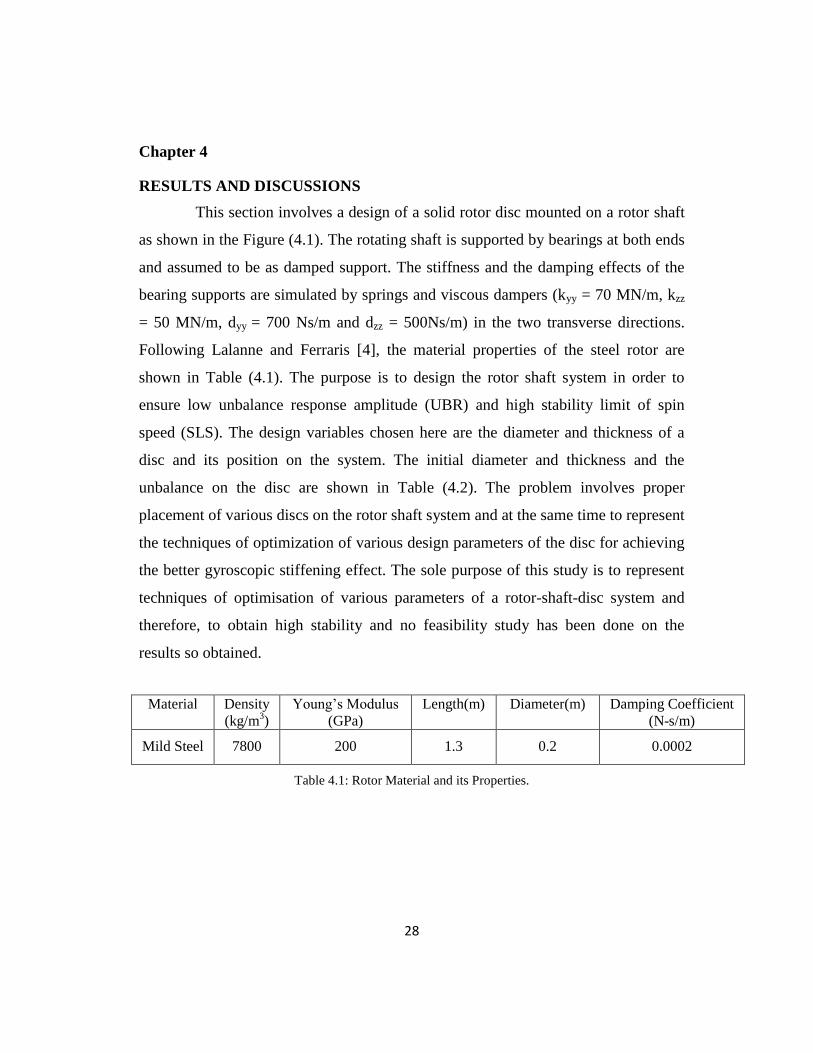
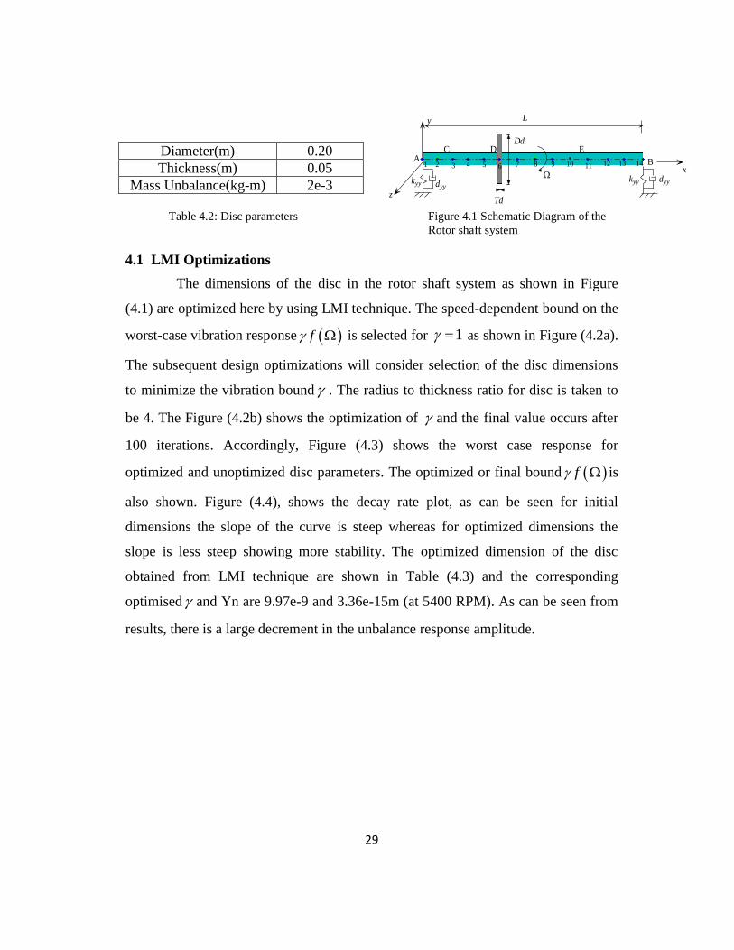
This section involves a design of a solid rotor disc mounted on a rotor shaft
as shown in the Figure (4.1). The rotating shaft is supported by bearings at both ends
and assumed to be as damped support. The stiffness and the damping effects of the
bearing supports are simulated by springs and viscous dampers (kyy = 70 MN/m, kzz
= 50 MN/m, dyy = 700 Ns/m and dzz = 500Ns/m) in the two transverse directions.
Following Lalanne and Ferraris [4], the material properties of the steel rotor are
shown in Table (4.1). The purpose is to design the rotor shaft system in order to
ensure low unbalance response amplitude (UBR) and high stability limit of spin
speed (SLS). The design variables chosen here are the diameter and thickness of a
disc and its position on the system. The initial diameter and thickness and the
unbalance on the disc are shown in Table (4.2). The problem involves proper
placement of various discs on the rotor shaft system and at the same time to represent
the techniques of optimization of various design parameters of the disc for achieving
the better gyroscopic stiffening effect. The sole purpose of this study is to represent
techniques of optimisation of various parameters of a rotor-shaft-disc system and
therefore, to obtain high stability and no feasibility study has been done on the
results so obtained.
Material Density
(kg/m3)
Young’s Modulus
(GPa)
Length(m) Diameter(m) Damping Coefficient
(N-s/m)
Mild Steel 7800 200 1.3 0.2 0.0002
Table 4.1: Rotor Material and its Properties.
29
x
y
z
kyy dyy
BA
dyykyy
C
L
D E
1 3 6542 10987 11 12 13 14
Dd
Td
Diameter(m) 0.20
Thickness(m) 0.05
Mass Unbalance(kg-m) 2e-3
Table 4.2: Disc parameters Figure 4.1 Schematic Diagram of the
Rotor shaft system
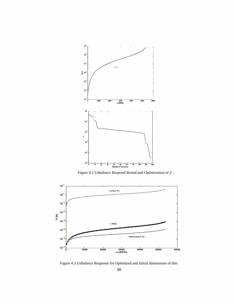
4.1 LMI Optimizations
The dimensions of the disc in the rotor shaft system as shown in Figure
(4.1) are optimized here by using LMI technique. The speed-dependent bound on the
worst-case vibration response f is selected for 1 as shown in Figure (4.2a).
The subsequent design optimizations will consider selection of the disc dimensions
to minimize the vibration bound . The radius to thickness ratio for disc is taken to
be 4. The Figure (4.2b) shows the optimization of and the final value occurs after
100 iterations. Accordingly, Figure (4.3) shows the worst case response for
optimized and unoptimized disc parameters. The optimized or final bound f is
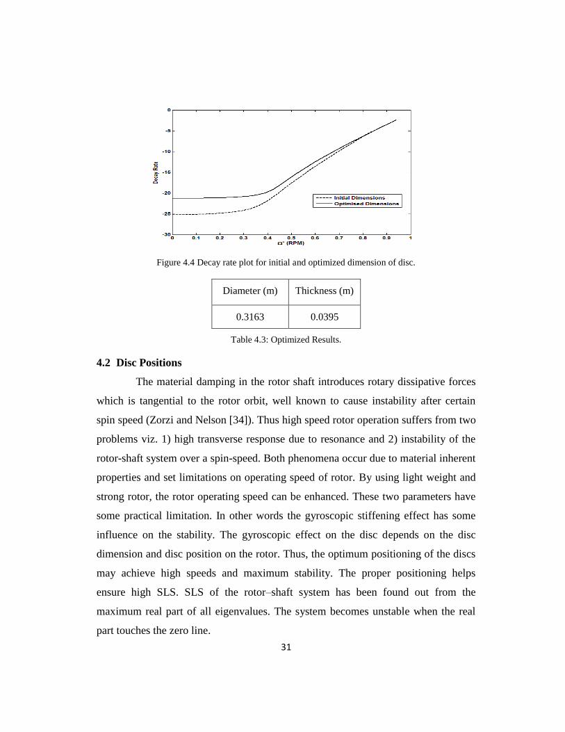
also shown. Figure (4.4), shows the decay rate plot, as can be seen for initial
dimensions the slope of the curve is steep whereas for optimized dimensions the
slope is less steep showing more stability. The optimized dimension of the disc
obtained from LMI technique are shown in Table (4.3) and the corresponding
optimised and Yn are 9.97e-9 and 3.36e-15m (at 5400 RPM). As can be seen from
results, there is a large decrement in the unbalance response amplitude.
30
Figure 4.2 Unbalance Respond Bound and Optimization of .
Figure 4.3 Unbalance Response for Optimized and Initial dimensions of disc
31
Figure 4.4 Decay rate plot for initial and optimized dimension of disc.
Diameter (m) Thickness (m)
0.3163 0.0395
Table 4.3: Optimized Results.
4.2 Disc Positions
The material damping in the rotor shaft introduces rotary dissipative forces
which is tangential to the rotor orbit, well known to cause instability after certain
spin speed (Zorzi and Nelson [34]). Thus high speed rotor operation suffers from two
problems viz. 1) high transverse response due to resonance and 2) instability of the
rotor-shaft system over a spin-speed. Both phenomena occur due to material inherent
properties and set limitations on operating speed of rotor. By using light weight and
strong rotor, the rotor operating speed can be enhanced. These two parameters have
some practical limitation. In other words the gyroscopic stiffening effect has some
influence on the stability. The gyroscopic effect on the disc depends on the disc
dimension and disc position on the rotor. Thus, the optimum positioning of the discs
may achieve high speeds and maximum stability. The proper positioning helps
ensure high SLS. SLS of the rotor–shaft system has been found out from the
maximum real part of all eigenvalues. The system becomes unstable when the real
part touches the zero line.
32
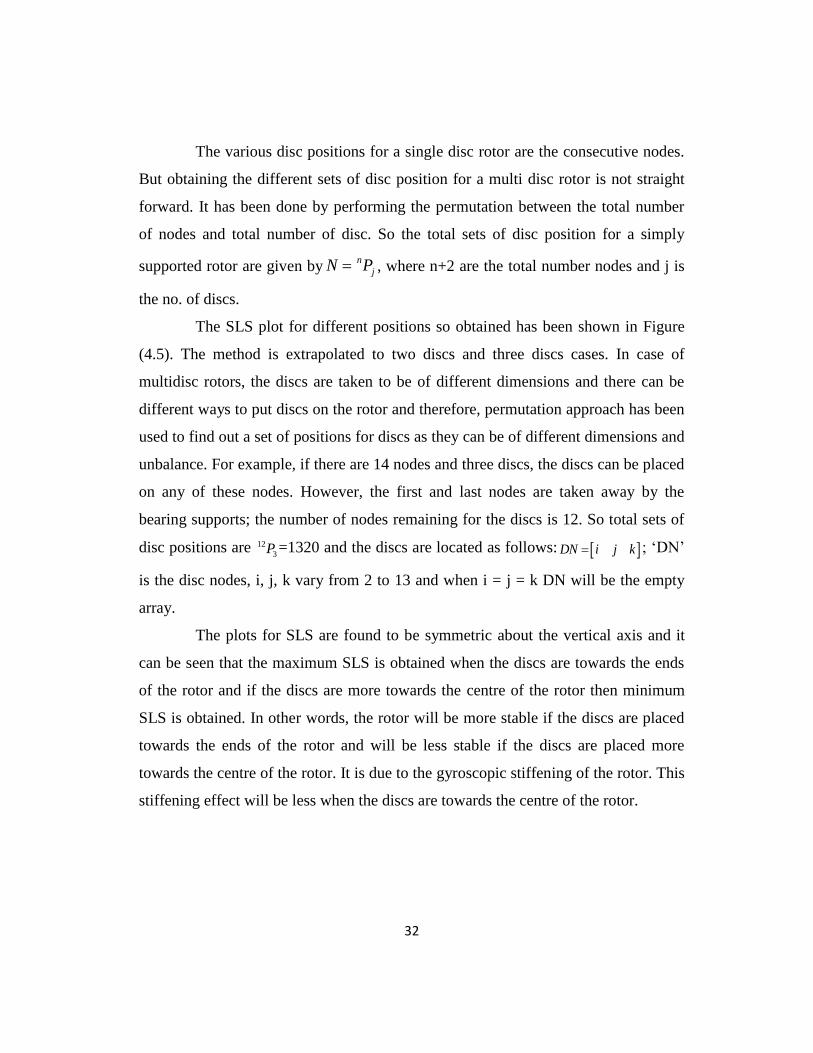
The various disc positions for a single disc rotor are the consecutive nodes.
But obtaining the different sets of disc position for a multi disc rotor is not straight
forward. It has been done by performing the permutation between the total number
of nodes and total number of disc. So the total sets of disc position for a simply
supported rotor are given byn
jN P , where n+2 are the total number nodes and j is
the no. of discs.
The SLS plot for different positions so obtained has been shown in Figure
(4.5). The method is extrapolated to two discs and three discs cases. In case of
multidisc rotors, the discs are taken to be of different dimensions and there can be
different ways to put discs on the rotor and therefore, permutation approach has been
used to find out a set of positions for discs as they can be of different dimensions and
unbalance. For example, if there are 14 nodes and three discs, the discs can be placed
on any of these nodes. However, the first and last nodes are taken away by the
bearing supports; the number of nodes remaining for the discs is 12. So total sets of
disc positions are 12
3P =1320 and the discs are located as follows: DN i j k ; ‘DN’
is the disc nodes, i, j, k vary from 2 to 13 and when i = j = k DN will be the empty
array.
The plots for SLS are found to be symmetric about the vertical axis and it
can be seen that the maximum SLS is obtained when the discs are towards the ends
of the rotor and if the discs are more towards the centre of the rotor then minimum
SLS is obtained. In other words, the rotor will be more stable if the discs are placed
towards the ends of the rotor and will be less stable if the discs are placed more
towards the centre of the rotor. It is due to the gyroscopic stiffening of the rotor. This
stiffening effect will be less when the discs are towards the centre of the rotor.
33
(a)
(b)
(c)
Figure 4.5 Effect on stability (SLS) of the system with position in case of one disc, two disc and three
disc rotors.
34
Chapter 5
CONCLUSIONS AND FUTURE SCOPE
5.1 Conclusions
The aim of this research is to gain insight into the gyroscopic effects on the
rotor disc system. For this purpose mathematical model of the system is used to
study its stability. Furthermore, optimisation techniques are utilised in order to
ensure high stability of the system under working conditions. The main
concentration was speed of the system as nowadays high speed rotors are of prime
importance because of the need for speedy works.
A literature survey has been carried out to investigate the developments in
modelling and optimisation techniques. It is observed that a huge amount of work
has been done in modelling different kinds of rotor with bearings. Most of them
involved the Finite Element Modelling. It was also, observed that a number of
researchers have used different optimisation techniques with different objective
functions in order to make rotor systems stable. However, the existing literature fails
to give us a technique that can be combined readily with today’s advanced
computation techniques and easy to handle both linear and non-linear systems. As a
consequence, it was decided to work on some technique that can fulfil the required
need.
Here, this work gives the equations of motion of a viscoelastic rotor-shaft
system. The linear viscoelastic rotor-material behaviour is represented in the time
domain where the damped shaft element is assumed to behave as Voigt model. The
finite element model is used to discretize the continuum which is based on Euler-
Bernoulli beam theory. Use of LMI technique has been shown here to optimize disc
dimension for high dynamic performance of the rotor shaft system. The advantage of
the proposed method is the flexibility offered by the LMI formulation, which can be
used to create design specifications concerning vibration amplitudes, stability,
critical speeds, modal damping levels, and parameter constraints. This work also
35
includes the effects of disc positions in a rotor system. Results are obtained for
different sets of disc positions to study the dynamic characteristics, where stability
limit of spin speed and unbalance response amplitude are two indices. The rotor will
be more stable if the discs are placed towards the ends of the rotor and will be less
stable if the discs are placed more towards the centre of the rotor. Thus, proper
placement of disc together with optimized dimensions will ensure high stability and
less response amplitude.
5.2 Proposed Future Work
Here, a linear system has been taken under study. The LMI technique can
handle non-linear systems as well. So, this work can be extrapolated to deal with a
non-linear system, which would be more realistic as the real time systems are more
non-linear than linear.
Also, the radius to thickness ratio is taken constant here. A polynomial
function can be used to specify the variable thickness of the disc and hence shape
optimisation of disc is possible. Multi-disc rotor with discs of different dimensions
and shapes could possibly be solved using LMIs.
There is a wide scope in the use of LMI technique. But there are currently
some drawbacks to the technique due to lack of fast and guaranteed methods to solve
bilinear matrix inequalities, which arise through the dependence of the system state-
space matrices on the design variables. The importance of developing improved
algorithms to solve this problem is widely recognised by researchers in the field of
numerical methods. With further development of these numerical tools, methods
based on LMIs would prove very useful in active and passive control systems.

36
Chapter 6
REFERENCES
[1] Boyd, S., Ghaoui, L. EI, Feron, E. and Balakrishnan, V., 1994, Linear Matrix
Inequalities in system and control theory, SIAM, Philadelphia.
[2] Gahinet, G., Nemirovski, A., Laub, A. J. and Chilai, M., 1995, LMI control
toolbox, The Mathworks, Inc..
[3] Genta, G., 1999, Dynamics of rotating systems, Springer Verlag.
[4] Lalanne, M. and Ferraris, G., 1998, Rotor dynamics prediction in engineering,
John Wiley and Sons.
[5] Rao, J. S., 1996, Rotor dynamics, New Age International Publishers.
[6] Stodola, A., 1927, Steam and gas turbines, McGraw-Hill, New York.
[7] Kandil, M. A., 2004, “On rotor internal damping instability”, Doctoral thesis,
Department of Mechanical Engineering, Imperial College of London.
[8] Dickmen, E., 2010, “Multiphysical effects on high-speed rotordynamics”,
Doctoral Thesis, University of Twente, Enschede, Netherlands.
[9] Belluzzo, G., 1905, “Le turbine a vapore ed a gas”, Hoepli, Milano, Italy.
[10] Bhavikatti, S. S. and Ramakrishnan, C. V., 1980, “Optimum shape design of
rotating discs”, Computers and Structures, Pergamon Press Ltd, 11, pp. 377-
401.
[11] Bulatovic, R. M., 1999, “A stability theorem for gyroscopic systems”, Acta
Mechanica, 136, pp. 119-124.
[12] Bulatovic, R. M., 2001, “Condition for instability of conservative gyroscopic
systems”, Theoretical and Applied Mechanics, 26, pp. 127-133.
[13] Bulatovic, R. M., 2001, “On the Lyapunov stability of linear conservative
gyroscopic systems”, C.R. Acad. Sci., Paris, 324, pp. 679-683.
[14] Bulatovic, R. M., 1997, “The stability of linear potential gyroscopic systems
when the potential energy has a maximum”, Journal of Applied Mathematics
and Mechanics, 61, pp. 371-375.
[15] Cao, Y. Y., Lam, J., Sun, X. Y., 1998, “Static output feedback: An ILMI
approach”, Automatica, 34 (12), pp. 1641-1645.
[16] Chen, T. Y., and Wang, B. P., 1993, “Optimum design of rotor-bearing system
with eigenvalue constraints”, Journal of Engineering for Gas Turbines and
Power, 115, pp. 256-260.
37
[17] Choi, B. G. and Yang, B. S., 2000, “Optimum shape design of rotor shaft using
genetic algorithm”, Journal of Vibration and Control, Sage Publication Inc., 6,
pp. 207-222.
[18] Cole, M. O., Wongratanaphisan, T. and Keogh, P. S., 2006, “On LMI-based
optimization of vibration and stability in rotor system design”, ASME Journal
of Engineering for Gas Turbines and Power, 128, pp. 679-684.
[19] Dutt, J. K. and Nakra, B. C., “Stability of rotor systems with viscoelastic
supports”, Journal of Sound and Vibration, 153 (1), pp. 89-96.
[20] Dutt, J. K. and Roy, H., 2011, “Viscoelastic Modelling of Rotor-Shaft Systems
using an operator based approach”, Journal of Mechanical Science, IMechE,
Part-C, 225, pp. 73-87.
[21] Foppl, A., 1895, “Das problem der laval’shen turbinewelle”, Civilingenieur,
pp. 332-342.
[22] Fujimori, A., 2004, “Optimisation of static output feedback using substitutive
LMI formulation”, IEEE Trans. Autom. Control, 49 (6), pp. 995-999.
[23] Gunter Edgar J. Jr., “Rotor bearing stability”, Proceedings of the First Turbo-
Machinery Symposium.
[24] Jafari, S., Hojjati, M. H. and Fathi, A., 2012, “Classical and modern
optimization methods in minimum weight design of elastic rotating discs with
variable thickness and density”, International Journal of Pressure Vessels and
Piping, 92, pp. 41-47.
[25] Jeffcott, H., 1919, “The lateral vibration of loaded shafts in the neighbourhood
of a whirling speed-the effect of want of balance”, Phil. Mag., 37 (6), pp. 304-
314.
[26] Nelson, H. D. and McVaugh, J. N., 1976, “The dynamics of rotor-bearing
system using finite elements”, Journal of Engineering for Industry, 98, pp.
593-600.
[27] Panda, K. C. and Dutt, J. K., 1999, “Design of optimum support parameters for
minimum rotor response and maximum stability limit”, Journal of Sound and
Vibration, 223 (1), pp. 1-21.
[28] Panda, K. C. and Dutt, J. K., 2003, “Optimum Support Characteristics for
Rotor–Shaft System with Preloaded Rolling Element Bearings”, Journal of
Sound and Vibration, 260, pp. 731–755.
[29] Rankine, W., 1869, “Centrifugal whirling of shafts”, The Engineer.
38
[30] Ranta, A. Matti, 1969, “On the optimum shape design of a rotating disc of any
isotropic material”, International Journal of Solid Structures, 5, pp. 1247-
1257.
[31] Shiau, T. N. and Chang, J. R., 1993, “Multi-objective optimization of rotor-
bearing system with critical speed constraints”, Journal of Engineering for Gas
Turbine and Power, 115, pp. 246-255.
[32] Stocki, R., Szolc, T., Tauzowski, P. and Knabel, J., 2012, “Robust design
optimization of the vibrating rotor-shaft system subjected to selected dynamic
constraints”, Mechanical Systems and Signal Processing, 29, pp. 34-44.
[33] VanAntwerp, J. and Braatz, 2000, R. D., “A tutorial on linear and bilinear
matrix inequalities”, Journal of Process Control, 10, pp. 363-385.
[34] Zorzi, E. S. and Nelson, H. D., 1977, “Finite element simulation of rotor-
bearing systems with internal damping”, ASME Journal of Engineering for
Power, 99, pp. 71-76.
39
LIST OF PUBLICATIONS
1) S. Chandraker, G. Maurya, H. Roy, 2012, “Optimization of discs position for
high stability of damped multi-disc rotor”, Proceedings of ICCMS, Dec 09-12,
IIT Hyderabad, India, Paper ID – 122.
2) S. Chandraker, G. Maurya, H. Roy, 2013, “Parameterized optimization of disc
for a damped rotor model using LMI approach”, accepted for the publications in
the proceeding of (ICOVP), September 09-12, Lisbon, Portugal, Paper ID – 551.