analysis of heat conduction in a disk brake system - unicampphoenics/em974/projetos/projetos 2...
TRANSCRIPT
ORIGINAL
Analysis of heat conduction in a disk brake system
Faramarz Talati Æ Salman Jalalifar
Received: 3 July 2008 / Accepted: 5 January 2009 / Published online: 27 January 2009
� Springer-Verlag 2009
Abstract In this paper, the governing heat equations for
the disk and the pad are extracted in the form of transient
heat equations with heat generation that is dependant to
time and space. In the derivation of the heat equations,
parameters such as the duration of braking, vehicle
velocity, geometries and the dimensions of the brake
components, materials of the disk brake rotor and the pad
and contact pressure distribution have been taken into
account. The problem is solved analytically using Green’s
function approach. It is concluded that the heat generated
due to friction between the disk and the pad should be
ideally dissipated to the environment to avoid decreasing
the friction coefficient between the disk and the pad and to
avoid the temperature rise of various brake components
and brake fluid vaporization due to excessive heating.
List of symbols
c Specific heat (J kg-1 K-1)
d1 Pad thickness (m)
d2 Disk thickness (m)
d _E Thermal energy per unit time (W)
dP Friction power (W)
Ec Kinetic energy (J)
Ff Friction force (N)
h Heat transfer coefficient (W m-2 K-1)
J0(�) Bessel’s function of the first kind
k Thermal conductivity (W m-1 K-1)
M Total vehicle mass (kg)
m Mass of the vehicle distributed on the front
axle (kg)
pmax Maximum pressure in the pad (N m-2)
p Pressure at radial distance r (N m-2)
_q Heat flux density (W m-2)
q0 Heat flux density at time t = 0 (W m-2)
r Space variable in radial distance (m)
r0 Dummy space variable in radial distance (m)
r1 Inner disk radius (m)
r2 Inner pad radius (m)
r3 Outer radius of the disk and the pad (m)
S Frictional surface (m2)
t Time (s)
tb Braking time (s)
T0 Initial temperature (K)
T? Ambient temperature (K)
Y0(�) Bessel’s function of the second kind
V Instantaneous velocity of the vehicle (m s-1)
V0 Initial velocity of the vehicle (m s-1)
z Space variable in axial direction (m)
z0 Dummy space variable in axial direction (m)
Greek symbolsa Thermal diffusivity (m s-2)
r Heat partition coefficient, dimensionless
/0 Pad contact angle (Rad)
n Thermal effusivity (Jm2 K-1 s-0.5)
q Mass density (kg m-3)
l Coefficient of friction, dimensionless
x Instantaneous angular velocity of the disk (s-1)
x0 Initial angular velocity of the disk (s-1)
s Dummy variable for time (s)
F. Talati � S. Jalalifar (&)
Faculty of Mechanical Engineering, University of Tabriz,
Tabriz, Iran
e-mail: [email protected]
F. Talati
e-mail: [email protected]
123
Heat Mass Transfer (2009) 45:1047–1059
DOI 10.1007/s00231-009-0476-y
Subscripts
d Disk
p Pad
1 Introduction
Recently, disk brakes have been widely used in light
vehicles. Proper performance of a vehicle brake system is
one of its advantages. Long repetitive braking leads to
temperature rise of various brake components of the
vehicle that reduces the performance of the brake system.
Long repetitive braking, such as one which occurs
during a mountain descent, will result in a brake fluid
temperature rise and may cause brake fluid vaporization.
This may be a concern particularly for passenger cars
equipped with aluminum calipers and with a limited air
flow to the wheel brake systems. Braking performance of a
vehicle can be significantly affected by the temperature rise
in the brake components. High temperature during braking
may cause brake fade, premature wear, brake fluid vapor-
ization, bearing failure, thermal cracks, and thermally
excited vibration. Therefore, it is important to predict the
temperature rise of a given brake system and assess its
thermal performance in the early design stage. Recently,
brake fluid vaporization has been suspected as a possible
cause of some collisions and a proper inspection procedure
has been recommended [1, 2].
Disk brakes are exposed to large thermal stresses during
routine braking and extraordinary thermal stresses during
hard braking. High-g decelerations typical of passenger
vehicles are known to generate temperatures as high as
900�C in a fraction of a second. These large temperature
excursions have two possible outcomes: thermal shock that
generates surface cracks; and/or large amounts of plastic
deformation in the brake rotor. In the absence of thermal
shock, a relatively small number of high-g braking cycles
are found to generate macroscopic cracks running through
the rotor thickness and along the radius of the disk brake
[3].
Heat generation due to friction in the sliding contact of
two bodies influences friction and wear characteristics of
brake systems. We note that numerous experimental evi-
dences suggest that the contact area is generally circular,
e.g. tread broke railway wheels exhibit circular thermally
affected zones on the surface [4].
According to Ostermeyer [5], the contact area in brake
systems shows characteristic structures. With respect to
wear, equilibrium of flow of growing and destruction of
hard patches is to be found on the contact surface. These
patches modulate the friction coefficient of the brake sys-
tem. Dealing with this principal wear mechanism of brake
pads the dynamic friction coefficient describes the
stationary and transient friction behavior of brake pads. For
instance the fading effect is the result of a temporary higher
destruction rate than the grow rate, when normal force and
velocity get high, up to that point, where the equilibrium of
flow of power is reached again on a lower level.
Gao and Lin [6] have presented an analytical model
for the determination of the contact temperature distri-
bution on the working surface of a brake. To consider
the effects of the moving heat source (the pad) with
relative sliding speed variation, a transient finite element
technique is used to characterize the temperature fields of
the solid rotor with appropriate thermal boundary con-
ditions. Numerical results shows that the operating
characteristics of the brake exert an essentially influence
on the surface temperature distribution and the maximal
contact temperature.
Dufrenoy [7] proposed a macrostructural model of the
thermomechanical behavior of the disk brake, taking into
account the real three-dimensional geometry of the disk–
pad couple. Contact surface variations, distortions and
wear are taken into account. Real body geometry and
thermoelastoplastic modeling of the disk material are
specially introduced. Such a model aims to give predictions
of the thermal gradients varying with time and of the
thermomechanical response of the components. Predictions
of the temperature distributions are compared with exper-
imental measurements obtained by thermographs and
thermocouples. Such a model seems to be a suitable base
for the study of the thermal dissipation and the thermo-
mechanical behavior and for the introduction of local
friction effects.
Formation of hot spots as well as non-uniform distri-
bution of the contact pressure is an unwanted effect
emerging in disk brakes in the course of braking or during
engagement of a transmission clutch. If the sliding velocity
is high enough, this effect can become unstable and can
result in disk material damage, frictional vibration, wear,
etc. [8].
Naji et al. [9] presented a mathematical model to
describe the thermal behavior of a brake system which
consists of the shoe and the drum. The model is solved
analytically using Green’s function method for any type of
the stopping braking action. The thermal behavior is
investigated for three specified braking actions which were
the impulse, the unit step and trigonometric stopping
actions.
Thermal response of disk brake systems to different
materials used for the disk–pad couple has been studied in
many researches [10–17].
Aerodynamic cooling of high performance disk brake
systems is investigated by many researchers [18–20].
This paper presents a mathematical model for describing
the thermal behavior of a disk brake system in a vehicle.
1048 Heat Mass Transfer (2009) 45:1047–1059
123
The time dependant heat equation is extracted from the
energy balance for the brake rotor and the pad. In deriva-
tion of the equations, different aspects with the assumption
of constant deceleration braking action have been consid-
ered including different pressure distributions. Appropriate
boundary conditions have been used to solve the governing
equations using Green’s function approach. Effects of
various design parameters, geometry and operating condi-
tions are taken into account.
2 Formulation of the problem
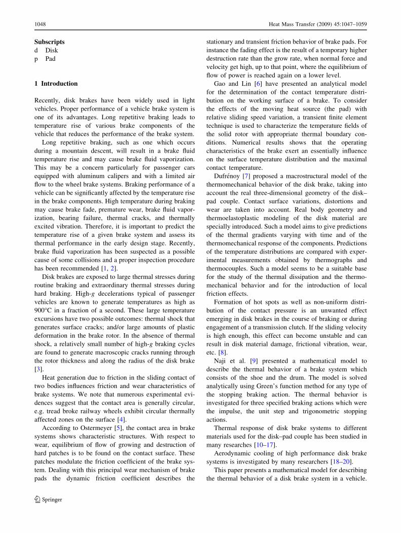
Figure 1 shows the disk brake system of a car and pad that
is separated from wheel assembly to better show the disk
and the pad in sliding contact. As it can be seen, typical
disk brake system and caliper assembly of a solid disk
brake rotor is completely noticeable. Figure 2 shows
schematic form of the disk and the pad in sliding contact.
2.1 Models of heat dissipation in disk brakes
2.1.1 Macroscopic model
Brakes are essentially a mechanism to change the energy
types. When a car is moving with speed, it has kinetic
energy. Applying the brakes, the pads or shoes that press
against the brake drum or rotor convert this energy into
thermal energy. The cooling of the brakes dissipates the
heat and the vehicle slows down. This is all to do with the
first law of thermodynamics, sometimes known as the law
of conservation of energy that states that energy cannot be
created nor destroyed; it can only be converted from one
form to another. In the case of brakes, it is converted from
kinetic energy to thermal energy:
Ec ¼1
2MV2
0 ð1Þ
where M is the total mass of the vehicle and V0 is the initial
speed of the vehicle. To obtain the amount of heat
dissipated by each of the front brake disks, we should know
the weight distribution of the vehicle. So the amount of
heat dissipated by each of the disks will be:
E ¼ 0:5� 1
2mV2
0 ¼ 0:25mV20 ð2Þ
where m is the amount of the distributed mass on the front
axle of the vehicle. Velocity of the vehicle slows down
with the assumption of constant deceleration:
V ¼ V0 1� t=tb
� �) x ¼ x0 1� t=tb
� �ð3Þ
2.1.2 Microscopic model
Rate of generated heat due to friction is equal to the friction
power. Some of this frictional heat is absorbed by the disk
and the rest is absorbed by the pads. Two kinds of thermal
contacts are usually used in analysis [21]:
(1) Perfect contact: considering the equal surface tem-
perature of the disk and the pad.
(2) Imperfect contact: considering a heat resistance
between the disk and the pad due to the formation
of the third body constituted by detached particles.
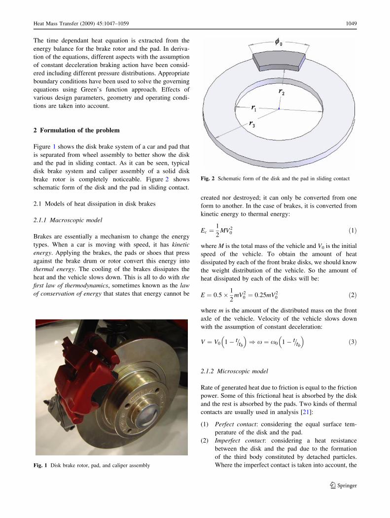
Where the imperfect contact is taken into account, theFig. 1 Disk brake rotor, pad, and caliper assembly
Fig. 2 Schematic form of the disk and the pad in sliding contact
Heat Mass Transfer (2009) 45:1047–1059 1049
123
heat partition coefficient is given by the following
equation:
r ¼ ndSd
ndSd þ npSp
ð4Þ
where np and nd are the thermal effusivities of the pad
and the disk and Sp and Sd are frictional contact
surfaces of the pad and the disk, respectively. Thermal
effusivity is defined as:
f ¼ffiffiffiffiffiffiffiffikqc
pð5Þ
To calculate the frictional heat generation at the contact
surfaces of two components of the brake system, para-
meters, e.g. the friction coefficient between two sliding
components, relative sliding velocity, geometry of the disk
brake rotor and the pad and the pressure distribution at
the sliding surfaces must be available. Here two types of
pressure distributions is considered:
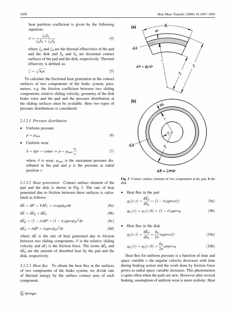
2.1.2.1 Pressure distribution
• Uniform pressure
p ¼ pmax ð6Þ
• Uniform wear
d ¼ kpr ¼ const) p ¼ pmax
r2
rð7Þ
where d is wear, pmax is the maximum pressure dis-
tributed in the pad and p is the pressure at radial
position r.
2.1.2.2 Heat generation Contact surface element of the
pad and the disk is shown in Fig. 3. The rate of heat
generated due to friction between these surfaces is calcu-
lated as follows:
d _E ¼ dP ¼ VdFf ¼ rxlp/0rdr ð8aÞ
d _E ¼ d _Ep þ d _Ed ð8bÞ
d _Ep ¼ ð1� rÞdP ¼ ð1� rÞlpx/0r2dr ð8cÞ
d _Ed ¼ rdP ¼ rlpx/0r2dr ð8dÞ
where d _E is the rate of heat generated due to friction
between two sliding components, V is the relative sliding
velocity and dFf is the friction force. The terms d _Ep and
d _Ed are the amount of absorbed heat by the pad and the
disk, respectively.
2.1.2.3 Heat flux To obtain the heat flux at the surfaces
of two components of the brake system, we divide rate
of thermal energy by the surface contact area of each
component.
• Heat flux in the pad
q1ðr; tÞ ¼d _Ep
dSp
¼ ð1� rÞlprxðtÞ ð9aÞ
q01ðrÞ ¼ q1ðr; 0Þ ¼ ð1� rÞlprx0 ð9bÞ
• Heat flux in the disk
q2ðr; tÞ ¼d _Ed
dSd
¼ /0
2prlprxðtÞ ð10aÞ
q02ðrÞ ¼ q2ðr; 0Þ ¼
/0
2plrprx0 ð10bÞ
Heat flux for uniform pressure is a function of time and
space variable r; the angular velocity decreases with time
during braking action and the work done by friction force
grows as radial space variable increases. This phenomenon
is quite often when the pads are new. However after several
braking, assumption of uniform wear is more realistic. Heat
Fig. 3 Contact surface element of two components a the pad, b the
disk
1050 Heat Mass Transfer (2009) 45:1047–1059
123
flux obtained for the uniform wear is just a function of time
and it is independent of the space variable; the work done
by friction force is the same at radial direction.
3 Governing equation for two components in sliding
contact
By looking at the mechanism of the disk brake, it may be
deduced that we have temperature gradient in / direction.
On the other hand, since the disk is turning, the temperature
gradient in / direction is negligible. Also experimental
investigations approve this phenomenon [4, 22]. So we can
assume that the pad acts on the entire circumferential angle
of the disk, so that the amount of generated heat is divided
by this hypothetical surface. Hence the heat equation for
the disk and the pad will be a function of r, z and t while
independent of /.
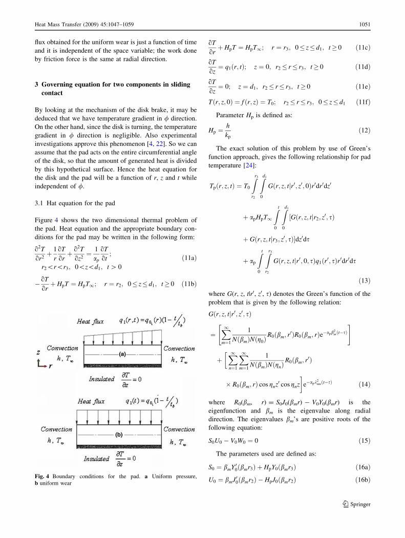
3.1 Hat equation for the pad
Figure 4 shows the two dimensional thermal problem of
the pad. Heat equation and the appropriate boundary con-
ditions for the pad may be written in the following form:
o2T
or2þ 1
r
oT
orþ o2T
oz2¼ 1
ap
oT
ot;
r2\r\r3; 0\z\d1; t [ 0
ð11aÞ
� oT
orþ HpT ¼ HpT1; r ¼ r2; 0� z� d1; t� 0 ð11bÞ
oT
orþ HpT ¼ HpT1; r ¼ r3; 0� z� d1; t� 0 ð11cÞ
oT
oz¼ q1ðr; tÞ; z ¼ 0; r2� r� r3; t� 0 ð11dÞ
oT
oz¼ 0; z ¼ d1; r2� r� r3; t� 0 ð11eÞ
Tðr; z; 0Þ ¼ f ðr; zÞ ¼ T0; r2� r� r3; 0� z� d1 ð11fÞ
Parameter Hp is defined as:
Hp ¼h
kp
ð12Þ
The exact solution of this problem by use of Green’s
function approach, gives the following relationship for pad
temperature [24]:
Tpðr; z; tÞ ¼ T0
Zr3
r2
Zd1
0
Gðr; z; tjr0; z0; 0Þr0dr0dz0
þ apHpT1
Z t
0
Zd1
0
Gðr; z; tjr2; z0; sÞ½
þ Gðr; z; tjr3; z0; sÞ�dz0ds
þ ap
Z t
0
Zr3
r2
Gðr; z; tjr0; 0; sÞq1ðr0; sÞr0dr0ds
ð13Þ
where G(r, z, t|r0, z0, s) denotes the Green’s function of the
problem that is given by the following relation:
Gðr; z; tjr0; z0; sÞ
¼X1m¼1
1
NðbmÞNðg0ÞR0ðbm; r
0ÞR0ðbm; rÞe�apb2mðt�sÞ
" #
þ�X1
n¼1
X1m¼1
1
NðbmÞNðgnÞR0ðbm; r
0Þ
� R0ðbm; rÞ cos gnz0 cos gnz
�e�apk
2nmðt�sÞ ð14Þ
where R0(bm, r) = S0J0(bmr) - V0Y0(bmr) is the
eigenfunction and bm is the eigenvalue along radial
direction. The eigenvalues bm’s are positive roots of the
following equation:
S0U0 � V0W0 ¼ 0 ð15Þ
The parameters used are defined as:
S0 ¼ bmY 00ðbmr3Þ þ HpY0ðbmr3Þ ð16aÞ
U0 ¼ bmJ00ðbmr2Þ � HpJ0ðbmr2Þ ð16bÞFig. 4 Boundary conditions for the pad. a Uniform pressure,
b uniform wear
Heat Mass Transfer (2009) 45:1047–1059 1051
123
V0 ¼ bmJ00ðbmr3Þ þ HpJ0ðbmr3Þ ð16cÞ
W0 ¼ bmY 00ðbmr2Þ � HpY0ðbmr2Þ ð16dÞ
B ¼ H2p þ b2
m ð16eÞ
1
NðbmÞ¼ p2
2
b2mU2
0
BðU20 � V2
0 Þð16fÞ
gn’s the eigenvalues along z direction and the eigen-
functions along z direction are obtained as follows:
Zðgn; zÞ ¼cos gnz; gn 6¼ 0
1; g0 ¼ 0
�ð17Þ
Eigenvalues gn’s are the positive roots of the following
equation:
sinðgnd1Þ ¼ 0) gn ¼npd1
n ¼ 0; 1; 2; . . .ð Þ ð18Þ
The norm along z direction is obtained from the
following relation:
1
NðgnÞ¼
2
d1
; gn 6¼ 0
1
d1
; g0 ¼ 0
8>><>>:
ð19Þ
The parameter knm is obtained from the following
relation:
k2nm ¼ g2
n þ b2m; k2
0m ¼ g20 þ b2
m ¼ b2m ð20Þ
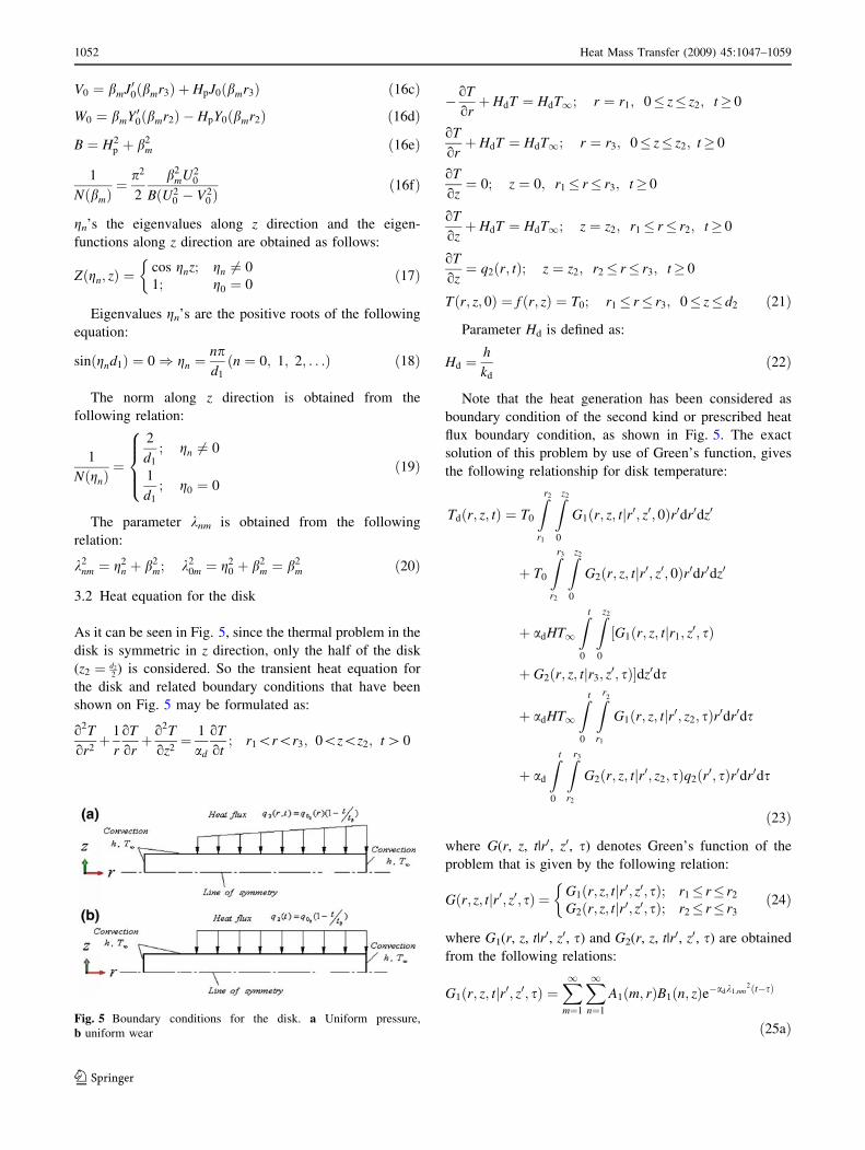
3.2 Heat equation for the disk
As it can be seen in Fig. 5, since the thermal problem in the
disk is symmetric in z direction, only the half of the disk
(z2 ¼ d2
2) is considered. So the transient heat equation for
the disk and related boundary conditions that have been
shown on Fig. 5 may be formulated as:
o2T
or2þ 1
r
oT
orþ o2T
oz2¼ 1
ad
oT
ot; r1\r\r3; 0\z\z2; t [0
� oT
orþ HdT ¼ HdT1; r ¼ r1; 0� z� z2; t� 0
oT
orþ HdT ¼ HdT1; r ¼ r3; 0� z� z2; t� 0
oT
oz¼ 0; z ¼ 0; r1� r� r3; t� 0
oT
ozþ HdT ¼ HdT1; z ¼ z2; r1� r� r2; t� 0
oT
oz¼ q2ðr; tÞ; z ¼ z2; r2� r� r3; t� 0
Tðr; z; 0Þ ¼ f ðr; zÞ ¼ T0; r1� r� r3; 0� z� d2 ð21Þ
Parameter Hd is defined as:
Hd ¼h
kd
ð22Þ
Note that the heat generation has been considered as
boundary condition of the second kind or prescribed heat
flux boundary condition, as shown in Fig. 5. The exact
solution of this problem by use of Green’s function, gives
the following relationship for disk temperature:
Tdðr; z; tÞ ¼ T0
Zr2
r1
Zz2
0
G1ðr; z; tjr0; z0; 0Þr0dr0dz0
þ T0
Zr3
r2
Zz2
0
G2ðr; z; tjr0; z0; 0Þr0dr0dz0
þ adHT1
Z t
0
Zz2
0
G1ðr; z; tjr1; z0; sÞ½
þ G2ðr; z; tjr3; z0; sÞ�dz0ds
þ adHT1
Z t
0
Zr2
r1
G1ðr; z; tjr0; z2; sÞr0dr0ds
þ ad
Z t
0
Zr3
r2
G2ðr; z; tjr0; z2; sÞq2ðr0; sÞr0dr0ds
ð23Þ
where G(r, z, t|r0, z0, s) denotes Green’s function of the
problem that is given by the following relation:
Gðr; z; tjr0; z0; sÞ ¼ G1ðr; z; tjr0; z0; sÞ; r1� r� r2
G2ðr; z; tjr0; z0; sÞ; r2� r� r3
�ð24Þ
where G1(r, z, t|r0, z0, s) and G2(r, z, t|r0, z0, s) are obtained
from the following relations:
G1ðr; z; tjr0; z0; sÞ ¼X1m¼1
X1n¼1
A1ðm; rÞB1ðn; zÞe�adk1;nm2ðt�sÞ
ð25aÞFig. 5 Boundary conditions for the disk. a Uniform pressure,
b uniform wear
1052 Heat Mass Transfer (2009) 45:1047–1059
123
G2ðr; z; tjr0; z0; sÞ ¼X1m¼1
A2ðm; rÞz2
e�adb2;m2ðt�sÞ
þX1n¼1
X1m¼1
A2ðm; rÞB2ðn; zÞe�adk2;nm2ðt�sÞ
ð25bÞ
where A1(m, r), A2(m, r), B1(n, z) and B2(n, z) are defined as:
A1ðm; rÞ ¼1
Nðb1;mÞR1ðb1;m; r
0ÞR1ðb1;m; rÞ ð26aÞ
A2ðm; rÞ ¼1
Nðb2;mÞR2ðb2;m; r
0ÞR2ðb2;m; rÞ ð26bÞ
B1ðn; zÞ ¼1
Nðg1;nÞZ1ðg1;n; z
0ÞZ1ðg1;n; zÞ ð26cÞ
B2ðn; zÞ ¼1
Nðg2;nÞZ2ðg2;n; z
0ÞZ2ðg2;n; zÞ ð26dÞ
The eigenvalues b1,m and b2,m are positive roots of the
following equations:
Zr2
r1
Zz2
0
r0G1ðr2; z; tjr0; z0; 0Þdz0dr0
¼Zr3
r2
Zz2
0
r0G2ðr2; z; tjr0; z0; 0Þdz0dr0 ð27aÞ
Zr2
r1
Zz2
0
r0oG1ðr; z; tjr0; z0; 0Þ
or
����r¼r2
dz0dr0
¼ �Zr3
r2
Zz2
0
r0oG2ðr; z; tjr0; z0; 0Þ
or
����r¼r2
dz0dr0 ð27bÞ
The eigenfunctions R1(b1,m, r) and R2(b2,m, r) are as
follows:
R1ðb1;m; rÞ ¼ U0J0ðb1;mrÞ �W0Y0ðb1;mrÞ ð28Þ
R2ðb2;m; rÞ ¼ S0J0ðb2;mr3Þ � V0Y0ðb2;mr3Þ ð29Þ
where the parameters used are defined as:
U0 ¼ b1Y 00ðb1r1Þ � HdY0ðb1r1Þ ð30aÞ
W0 ¼ b1J00ðb1r1Þ � HdJ0ðb1r1Þ ð30bÞ
V0 ¼ b2J00ðb2r3Þ þ HdJ0ðb2r3Þ ð30cÞ
S0 ¼ b2Y 00ðb2r3Þ þ HdY0ðb2r3Þ ð30dÞ
The eigenfunctions Z1(g1,n, z) Z2(g2,n, z) are defined as
follows:
Z1ðg1;n; zÞ ¼ cosðg1;nzÞ ð31Þ
Z2ðg2;n; zÞ ¼cosðg2;nzÞ; g2;n 6¼ 0
1; g2;0 ¼ 0
(ð32Þ
The eigenvalues g1,n’s are the positive roots of the fol-
lowing equation:
g1;n tanðg1;nz2Þ ¼ Hd ð33Þ
and the eigenvalues g2,n’s are the positive roots of the
following equation:
sinðg2;nz2Þ ¼ 0) g2;n ¼npz2
; n ¼ 0; 1; 2; . . . ð34Þ
and the norms are obtained from the following relation:
1
Nðg1;nÞ¼
2ðg21;n þ H2Þ
z2ðg21;n þ H2Þ þ H
ð35Þ
1
Nðg2;nÞ¼
2
z2
; g2;n 6¼ 0
1
z2
; g2;0 ¼ 0
8>><>>:
ð36Þ
4 Automotive brake application
Consider the automotive disk brake issued from literature
data. The details of the dimensions and operating condi-
tions are given in Table 1. The disk material is steel while
the pad material is made of an organic matrix composite.
Their physical properties at room temperature are detailed
in Table 2.
5 Results and discussion
Figure 6 shows the disk surface temperatures with respect
to time. As it can be seen the current work results assuming
uniform wear, are in a good agreement with Limpert and
Newcomb models.
Maximum contact surface temperatures of the pad
and the disk for two types of pressure distributions are
illustrated in Fig. 7. Maximum temperature obtained for
uniform pressure distribution is higher than that for uni-
form wear. The reason is that with the assumption of
uniform pressure, the work done by friction force grows as
the radius increases. Meanwhile the work done by friction
force with the assumption of uniform wear does not vary
with radius. Moreover the mean value of the surface tem-
perature for the two pressure distribution is the same. As it
can be seen, the difference between the surface temperature
of the disk and the pad is relatively high. This is due to the
thermal resistance between the disk and the pad, consti-
tuted by the accumulation of wear particles that form a thin
layer (usually called third body). Therefore, this thermal
resistance causes a heat partition between the disk and the
pad.
Heat Mass Transfer (2009) 45:1047–1059 1053
123
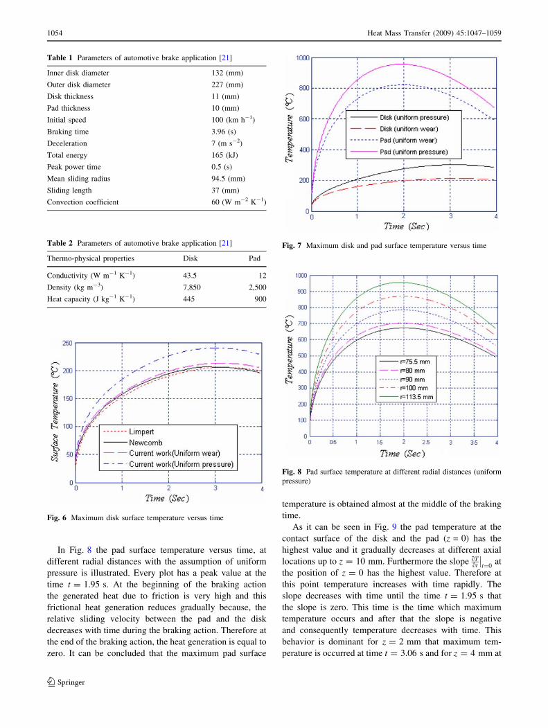
In Fig. 8 the pad surface temperature versus time, at
different radial distances with the assumption of uniform
pressure is illustrated. Every plot has a peak value at the
time t = 1.95 s. At the beginning of the braking action
the generated heat due to friction is very high and this
frictional heat generation reduces gradually because, the
relative sliding velocity between the pad and the disk
decreases with time during the braking action. Therefore at
the end of the braking action, the heat generation is equal to
zero. It can be concluded that the maximum pad surface
temperature is obtained almost at the middle of the braking
time.
As it can be seen in Fig. 9 the pad temperature at the
contact surface of the disk and the pad (z = 0) has the
highest value and it gradually decreases at different axial
locations up to z = 10 mm. Furthermore the slope oTot
��t¼0
at
the position of z = 0 has the highest value. Therefore at
this point temperature increases with time rapidly. The
slope decreases with time until the time t = 1.95 s that
the slope is zero. This time is the time which maximum
temperature occurs and after that the slope is negative
and consequently temperature decreases with time. This
behavior is dominant for z = 2 mm that maximum tem-
perature is occurred at time t = 3.06 s and for z = 4 mm at
Table 1 Parameters of automotive brake application [21]
Inner disk diameter 132 (mm)
Outer disk diameter 227 (mm)
Disk thickness 11 (mm)
Pad thickness 10 (mm)
Initial speed 100 (km h-1)
Braking time 3.96 (s)
Deceleration 7 (m s-2)
Total energy 165 (kJ)
Peak power time 0.5 (s)
Mean sliding radius 94.5 (mm)
Sliding length 37 (mm)
Convection coefficient 60 (W m-2 K-1)
Table 2 Parameters of automotive brake application [21]
Thermo-physical properties Disk Pad
Conductivity (W m-1 K-1) 43.5 12
Density (kg m-3) 7,850 2,500
Heat capacity (J kg-1 K-1) 445 900
Fig. 6 Maximum disk surface temperature versus time
Fig. 7 Maximum disk and pad surface temperature versus time
Fig. 8 Pad surface temperature at different radial distances (uniform
pressure)
1054 Heat Mass Transfer (2009) 45:1047–1059
123
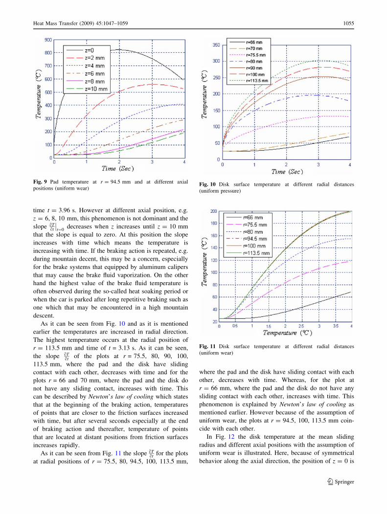
time t = 3.96 s. However at different axial position, e.g.
z = 6, 8, 10 mm, this phenomenon is not dominant and the
slope oTot
��t¼0
decreases when z increases until z = 10 mm
that the slope is equal to zero. At this position the slope
increases with time which means the temperature is
increasing with time. If the braking action is repeated, e.g.
during mountain decent, this may be a concern, especially
for the brake systems that equipped by aluminum calipers
that may cause the brake fluid vaporization. On the other
hand the highest value of the brake fluid temperature is
often observed during the so-called heat soaking period or
when the car is parked after long repetitive braking such as
one which that may be encountered in a high mountain
descent.
As it can be seen from Fig. 10 and as it is mentioned
earlier the temperatures are increased in radial direction.
The highest temperature occurs at the radial position of
r = 113.5 mm and time of t = 3.13 s. As it can be seen,
the slope oTot of the plots at r = 75.5, 80, 90, 100,
113.5 mm, where the pad and the disk have sliding
contact with each other, decreases with time and for the
plots r = 66 and 70 mm, where the pad and the disk do
not have any sliding contact, increases with time. This
can be described by Newton’s law of cooling which states
that at the beginning of the braking action, temperatures
of points that are closer to the friction surfaces increased
with time, but after several seconds especially at the end
of braking action and thereafter, temperature of points
that are located at distant positions from friction surfaces
increases rapidly.
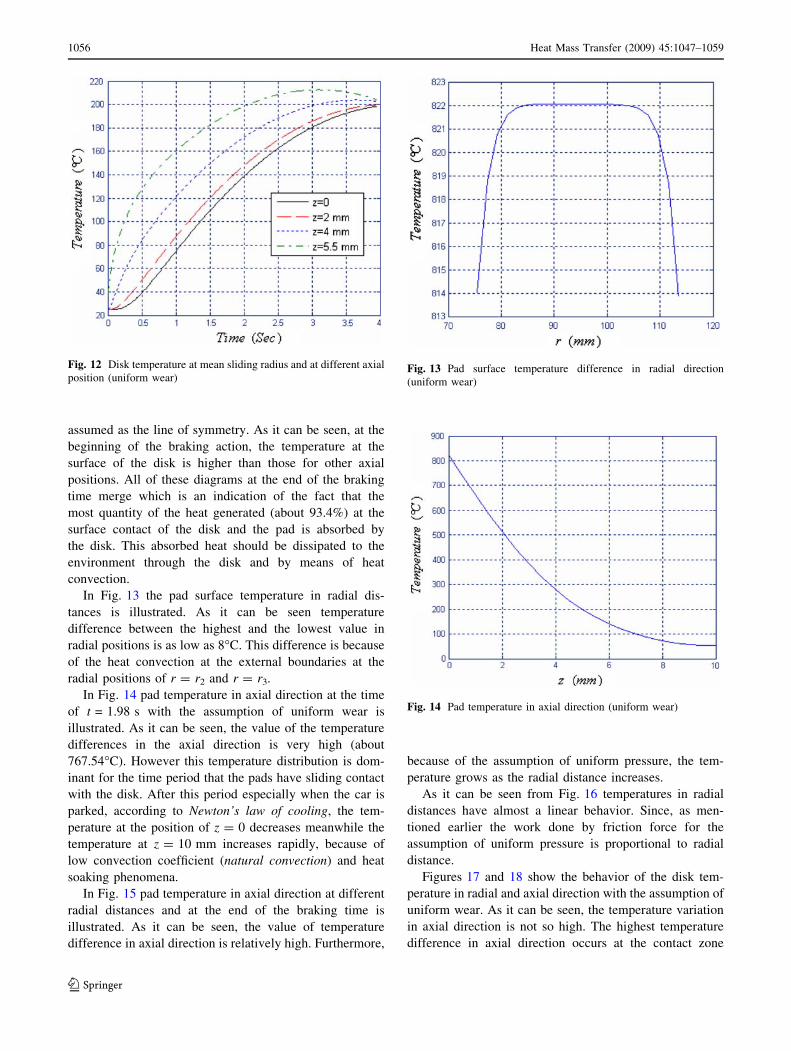
As it can be seen from Fig. 11 the slope oTot for the plots
at radial positions of r = 75.5, 80, 94.5, 100, 113.5 mm,
where the pad and the disk have sliding contact with each
other, decreases with time. Whereas, for the plot at
r = 66 mm, where the pad and the disk do not have any
sliding contact with each other, increases with time. This
phenomenon is explained by Newton’s law of cooling as
mentioned earlier. However because of the assumption of
uniform wear, the plots at r = 94.5, 100, 113.5 mm coin-
cide with each other.
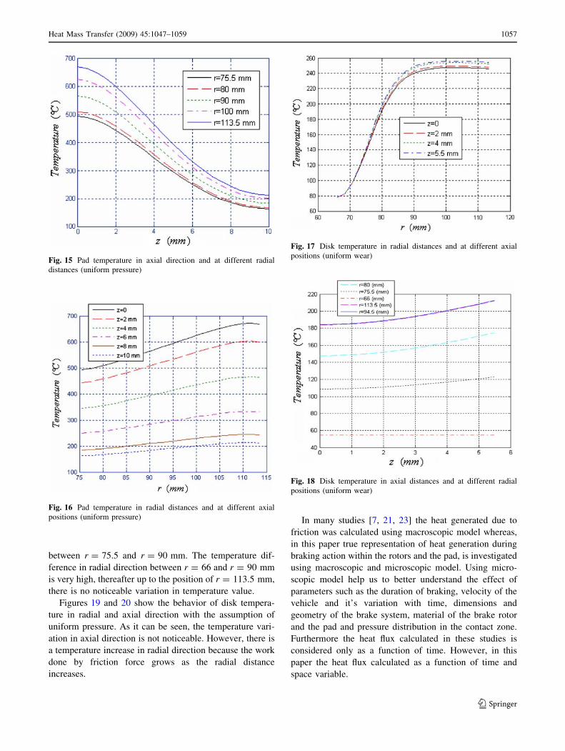
In Fig. 12 the disk temperature at the mean sliding
radius and different axial positions with the assumption of
uniform wear is illustrated. Here, because of symmetrical
behavior along the axial direction, the position of z = 0 is
Fig. 9 Pad temperature at r = 94.5 mm and at different axial
positions (uniform wear)Fig. 10 Disk surface temperature at different radial distances
(uniform pressure)
Fig. 11 Disk surface temperature at different radial distances
(uniform wear)
Heat Mass Transfer (2009) 45:1047–1059 1055
123
assumed as the line of symmetry. As it can be seen, at the
beginning of the braking action, the temperature at the
surface of the disk is higher than those for other axial
positions. All of these diagrams at the end of the braking
time merge which is an indication of the fact that the
most quantity of the heat generated (about 93.4%) at the
surface contact of the disk and the pad is absorbed by
the disk. This absorbed heat should be dissipated to the
environment through the disk and by means of heat
convection.
In Fig. 13 the pad surface temperature in radial dis-
tances is illustrated. As it can be seen temperature
difference between the highest and the lowest value in
radial positions is as low as 8�C. This difference is because
of the heat convection at the external boundaries at the
radial positions of r = r2 and r = r3.
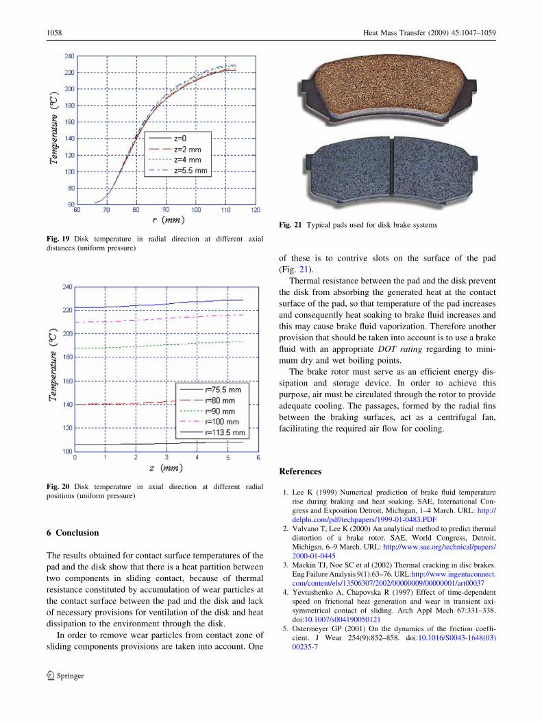
In Fig. 14 pad temperature in axial direction at the time
of t = 1.98 s with the assumption of uniform wear is
illustrated. As it can be seen, the value of the temperature
differences in the axial direction is very high (about
767.54�C). However this temperature distribution is dom-
inant for the time period that the pads have sliding contact
with the disk. After this period especially when the car is
parked, according to Newton’s law of cooling, the tem-
perature at the position of z = 0 decreases meanwhile the
temperature at z = 10 mm increases rapidly, because of
low convection coefficient (natural convection) and heat
soaking phenomena.
In Fig. 15 pad temperature in axial direction at different
radial distances and at the end of the braking time is
illustrated. As it can be seen, the value of temperature
difference in axial direction is relatively high. Furthermore,
because of the assumption of uniform pressure, the tem-
perature grows as the radial distance increases.
As it can be seen from Fig. 16 temperatures in radial
distances have almost a linear behavior. Since, as men-
tioned earlier the work done by friction force for the
assumption of uniform pressure is proportional to radial
distance.
Figures 17 and 18 show the behavior of the disk tem-
perature in radial and axial direction with the assumption of
uniform wear. As it can be seen, the temperature variation
in axial direction is not so high. The highest temperature
difference in axial direction occurs at the contact zone
Fig. 12 Disk temperature at mean sliding radius and at different axial
position (uniform wear)Fig. 13 Pad surface temperature difference in radial direction
(uniform wear)
Fig. 14 Pad temperature in axial direction (uniform wear)
1056 Heat Mass Transfer (2009) 45:1047–1059
123
between r = 75.5 and r = 90 mm. The temperature dif-
ference in radial direction between r = 66 and r = 90 mm
is very high, thereafter up to the position of r = 113.5 mm,
there is no noticeable variation in temperature value.
Figures 19 and 20 show the behavior of disk tempera-
ture in radial and axial direction with the assumption of
uniform pressure. As it can be seen, the temperature vari-
ation in axial direction is not noticeable. However, there is
a temperature increase in radial direction because the work
done by friction force grows as the radial distance
increases.
In many studies [7, 21, 23] the heat generated due to
friction was calculated using macroscopic model whereas,
in this paper true representation of heat generation during
braking action within the rotors and the pad, is investigated
using macroscopic and microscopic model. Using micro-
scopic model help us to better understand the effect of
parameters such as the duration of braking, velocity of the
vehicle and it’s variation with time, dimensions and
geometry of the brake system, material of the brake rotor
and the pad and pressure distribution in the contact zone.
Furthermore the heat flux calculated in these studies is
considered only as a function of time. However, in this
paper the heat flux calculated as a function of time and
space variable.
Fig. 15 Pad temperature in axial direction and at different radial
distances (uniform pressure)
Fig. 16 Pad temperature in radial distances and at different axial
positions (uniform pressure)
Fig. 17 Disk temperature in radial distances and at different axial
positions (uniform wear)
Fig. 18 Disk temperature in axial distances and at different radial
positions (uniform wear)
Heat Mass Transfer (2009) 45:1047–1059 1057
123
6 Conclusion
The results obtained for contact surface temperatures of the
pad and the disk show that there is a heat partition between
two components in sliding contact, because of thermal
resistance constituted by accumulation of wear particles at
the contact surface between the pad and the disk and lack
of necessary provisions for ventilation of the disk and heat
dissipation to the environment through the disk.
In order to remove wear particles from contact zone of
sliding components provisions are taken into account. One
of these is to contrive slots on the surface of the pad
(Fig. 21).
Thermal resistance between the pad and the disk prevent
the disk from absorbing the generated heat at the contact
surface of the pad, so that temperature of the pad increases
and consequently heat soaking to brake fluid increases and
this may cause brake fluid vaporization. Therefore another
provision that should be taken into account is to use a brake
fluid with an appropriate DOT rating regarding to mini-
mum dry and wet boiling points.
The brake rotor must serve as an efficient energy dis-
sipation and storage device. In order to achieve this
purpose, air must be circulated through the rotor to provide
adequate cooling. The passages, formed by the radial fins
between the braking surfaces, act as a centrifugal fan,
facilitating the required air flow for cooling.
References
1. Lee K (1999) Numerical prediction of brake fluid temperature
rise during braking and heat soaking. SAE, International Con-
gress and Exposition Detroit, Michigan, 1–4 March. URL: http://
delphi.com/pdf/techpapers/1999-01-0483.PDF
2. Valvano T, Lee K (2000) An analytical method to predict thermal
distortion of a brake rotor. SAE, World Congress, Detroit,
Michigan, 6–9 March. URL: http://www.sae.org/technical/papers/
2000-01-0445
3. Mackin TJ, Noe SC et al (2002) Thermal cracking in disc brakes.
Eng Failure Analysis 9(1):63–76. URL:http://www.ingentaconnect.
com/content/els/13506307/2002/00000009/00000001/art00037
4. Yevtushenko A, Chapovska R (1997) Effect of time-dependent
speed on frictional heat generation and wear in transient axi-
symmetrical contact of sliding. Arch Appl Mech 67:331–338.
doi:10.1007/s004190050121
5. Ostermeyer GP (2001) On the dynamics of the friction coeffi-
cient. J Wear 254(9):852–858. doi:10.1016/S0043-1648(03)
00235-7
Fig. 19 Disk temperature in radial direction at different axial
distances (uniform pressure)
Fig. 20 Disk temperature in axial direction at different radial
positions (uniform pressure)
Fig. 21 Typical pads used for disk brake systems
1058 Heat Mass Transfer (2009) 45:1047–1059
123
6. Gao CH, Lin XZ (2002) Transient temperature field analysis of a
brake in a non-axisymmetric three-dimensional model. J Mat
Proc Tech 129:513–517. doi:10.1016/S0924-0136(02)00622-2
7. Dufrenoy P (2004) Two-/three-dimensional hybrid model of the
thermomechanical behavior of disc brakes. J Rail Rapid Transit
Part F 218:17–30. doi:10.1243/095440904322804402
8. Voldrich J (2006) Frictionally excited thermoelastic instability in
disc brakes—Transient problem in the full contact regime. Int J
Mech Sci 49(2):129–137. doi:10.1016/j.ijmecsci.2006.08.008
9. Naji M, Al-Nimr M, Masoud S (2000) Transient thermal behavior
of a cylindrical brake system. J Heat Mass Transf 36:45–49
10. Mosleh M, Blau PJ, Dumitrescu D (2004) Characteristics and
morphology of wear particles from laboratory testing of disk
brake materials. J Wear 256:1128–1134. doi:10.1016/j.wear.
2003.07.007
11. Mutlu I, Alma MH, Basturk MA (2005) Preparation and char-
acterization of brake linings from modified tannin-phenol
formaldehyde resin and asbestos-free fillers. J Mat Sci 40(11):
3003–3005. doi:10.1007/s10853-005-2396-7
12. Hecht RL, Dinwiddie RB, Wang H (1999) The effect of graphite
flake morphology on the thermal diffusivity of gray cast irons
used for automotive brake discs. J Mat Sci 34(19):4775–4781.
doi:10.1023/A:1004643322951
13. Gudmand-Høyer L, Bach A, Nielsen GT, Morgen P (1999) Tri-
bological properties of automotive disc brakes with solid
lubricants. J Wear 232(2):168–175. doi:10.1016/S0043-1648(99)
00142-8
14. Uyyuru RK, Surappa MK, Brusethaug S (2007) Tribological
behavior of Al–Si–SiCp composites/automobile brake pad system
under dry sliding conditions. J Tribol Int 40(2):365–373. doi:
10.1016/j.triboint.2005.10.012
15. Cho MH, Cho KH, Kim SJ, Kim DH, Jang H (2005) The role of
transfer layers on friction characteristics in the sliding interface
between friction materials against gray iron brake disks. Trib Lett
20(2):101–108. doi:10.1007/s11249-005-8299-6
16. Boz M, Kurt A (2007) The effect of Al2O3 on the friction per-
formance of automotive brake friction materials. J Tribo Int
40(7):1161–1169. doi:10.1016/j.triboint.2006.12.004
17. Blau PJ, McLaughlin JC (2003) Effects of water films and sliding
speed on the frictional behavior of truck disc brake material. Trib
Int 36(10):709–715. doi:10.1016/S0301-679X(03)00026-4
18. McPhee AD, Johnson DA (2007) Experimental heat transfer and
flow analysis of a vented brake rotor. Int J Thermal Sci
47(4):458–467. doi:10.1016/j.ijthermalsci.2007.03.006
19. Wallis L, Leonardi E, Milton B, Joseph P (2002) Air flow and
heat transfer in ventilated disk brake rotors with diamond and
tear-drop pillars. Numer Heat Transf Part A 41:643–655. URL:
http://openurl.ingenta.com/content?genre=article&issn=1040-778
2&volume=41&issue=6-7&spage=643&epage=655
20. Johnson DA, Sperandei BA, Gilbert R (2003) Analysis of the
flow through a vented automotive brake rotor. J Fluids Eng
125:979–986. doi:10.1115/1.1624426
21. Majcherczak D, Dufrenoy P, Naıt-Abdelaziz M (2005) Third
body influence on thermal friction contact problems: application
to braking. J Tribol 127:89–95. doi:10.1115/1.1757490
22. Majcherczak D, Dufrenoy P, Berthier Y (2007) Tribological,
thermal and mechanical coupling aspects of the dry sliding contact.
Tribol Int 40:834–843. doi:10.1016/j.triboint.2006.08.004
23. Gotowicki PF, Nigrelli V, Mariotti GV, Aleksendric D, Duboka
C (2005) Numerical and experimental analysis of a Pegs-Wing
ventilated disk brake rotor, with pads and cylinders. 10th EAEC
European Automotive Congress, Serbia, Serbia and Montenegro,
30th May–1st June 2005, EAEC05YU-AS04. URL:http://www.
atnet.it/lista/EAEC05YU-AS04.pdf
24. Ozisik MN (1993) Heat conduction, Chap 3 and 6, 2nd edn. John
Wiley, New York
Heat Mass Transfer (2009) 45:1047–1059 1059
123