analysis of major changes to arrester standards iec 60099-4...analysis of major changes to arrester...
TRANSCRIPT

Analysis of Major Changes to Arrester Standards IEC 60099-4
STEVE BREWER

Analysis of Major Changes to Arrester Standard IEC 60099-4
2015 INMR World Congress October 18 - 21 Munich, Germany
Steve Brewer- Senior Product Manager - HPS Arrester Business Unit

®
Agenda
• Fundamental Differences between IEC 60099-4 Edition 2.2 and Edition 3.0– Arrester Classification
– Arrester Type Tests• Repetitive Charge Transfer
• Operating Duty
• Power-frequency voltage versus time
• Arrester disconnector / fault indicator
• Weather ageing test – polymer
2015 INMR World Congress October 18 - 21 Munich, Germany

®
IEC Arrester Classifications
Arrester Class Station Distribution
Designation SH SM SL DH DM DL
Nominal discharge current 20 kA 10 kA 10 kA 10 kA 5 kA 2.5 kA
Switching impulse discharge current2 kA 1 kA 0.5 kA -- -- --
Qrs (Coulombs) ≥ 2.4 ≥ 1.6 ≥ 1.0 ≥ 0.4 ≥ 0.2 ≥ 0.1
W th (kJ/kV of Rated Voltage) ≥ 10 ≥ 7 ≥ 4 -- -- --
Qth (Coulombs) -- -- -- ≥ 1.1 ≥ 0.7 ≥ 0.45
Edit
ion
3.0
Edit
ion
2.2
Standard nominal discharge current
20 000 A 10 000 A 5 000 A 2 500 A
Rated Voltage Ur (kV rms) 360 < Ur < 756 3 < Ur < 360 Ur ≤ 132 Ur ≤ 36
• Classifications now more associated with application
• Now 6 classes instead of 4, more finely divided according to expected duty
• Addition of the definitions for “distribution” and “substation”
MAIN
CHANGES
2015 INMR World Congress October 18 - 21 Munich, Germany

®
IEC Arrester ClassificationsArrester Class Station Distribution
Designation SH SM SL DH DM DL
Nominal discharge current 20 kA 10 kA 10 kA 10 kA 5 kA 2.5 kA
Switching impulse discharge current2 kA 1 kA 0.5 kA -- -- --
Qrs (Coulombs) ≥ 2.4 ≥ 1.6 ≥ 1.0 ≥ 0.4 ≥ 0.2 ≥ 0.1
W th (kJ/kV of Rated Voltage) ≥ 10 ≥ 7 ≥ 4 -- -- --
Qth (Coulombs) -- -- -- ≥ 1.1 ≥ 0.7 ≥ 0.45
Edit
ion
3.0
Distribution Class Arrester – intended for use on distribution systems to protect components primarily from the effects of lightning.
Station Class Arrester – intended for use in stations to protect the equipment from transient over-voltages.
2015 INMR World Congress October 18 - 21 Munich, Germany

®
IEC Arrester ClassificationsArrester Class Station Distribution
Designation SH SM SL DH DM DL
Nominal discharge current 20 kA 10 kA 10 kA 10 kA 5 kA 2.5 kA
Switching impulse discharge current2 kA 1 kA 0.5 kA -- -- --
Qrs (Coulombs) ≥ 2.4 ≥ 1.6 ≥ 1.0 ≥ 0.4 ≥ 0.2 ≥ 0.1
W th (kJ/kV of Rated Voltage) ≥ 10 ≥ 7 ≥ 4 -- -- --
Qth (Coulombs) -- -- -- ≥ 1.1 ≥ 0.7 ≥ 0.45
Edit
ion
3
.0
SH = Station High dutySM = Station Medium dutySL = Station Low duty
DH = Distribution High dutyDM = Distribution Medium dutyDL = Distribution Low duty
Sub-classifications – within each class there are designations relating to the duty that the arrester will experience as noted below.
2015 INMR World Congress October 18 - 21 Munich, Germany
®
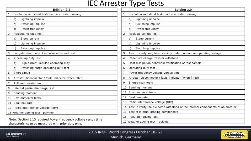
IEC Arrester Type TestsEdition 3.0
1 Insulation withstand tests on the arrester housing
a) Lightning impulse
b) Switching impulse
c) Power-frequency
2 Residual voltage test
a) Steep current
b) Lightning impulse
c) Switching impulse
3 Test to verify long term stability under continuous operating voltage
4 Repetitive charge transfer withstand
5 Heat dissipation behaviour verification of test sample
6 Operating duty test
7 Power-frequency voltage versus time
8 Arrester disconnector / fault indicator (when fitted)
9 Short-circuit tests
10 Bending moment
11 Environmental tests
12 Seal leak rate
13 Radio interference voltage (RIV)
14 Test to verify the dielectric withstand of the internal components of an arrester
15 Test of internal grading components
16 Polluted housing test
17 Weather ageing test – polymer
Edition 2.2
1 Insulation withstand tests on the arrester housing
a) Lightning impulse
b) Switching impulse
c) Power-frequency
2 Residual voltage test
a) Steep current
b) Lightning impulse
c) Switching impulse
3 Long-duration current impulse withstand test
4 Operating duty test
a) High-current impulse operating duty
b) Switching surge operating duty test
5 Short circuit
6 Arrester disconnector / fault indicator (when fitted)
7 Polluted housing test
8 Internal partial discharge test
9 Bending moment
10 Environmental tests
11 Seal leak rate
12 Radio interference voltage (RIV)
13 Weather ageing test - polymer
Note: Section 6.10 required Power-frequency voltage versus time characteristics to be measured with prior duty only.
2015 INMR World Congress October 18 - 21 Munich, Germany
®
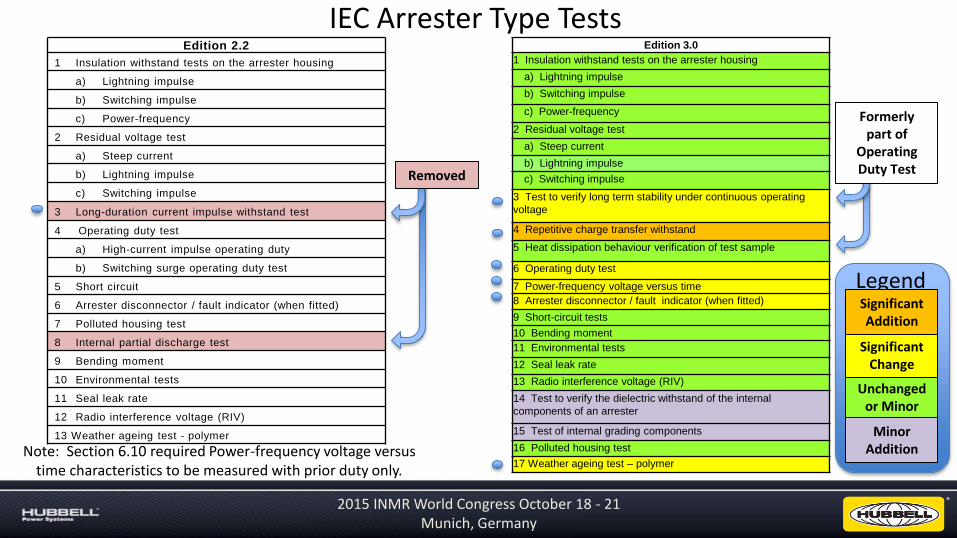
IEC Arrester Type TestsEdition 2.2
1 Insulation withstand tests on the arrester housing
a) Lightning impulse
b) Switching impulse
c) Power-frequency
2 Residual voltage test
a) Steep current
b) Lightning impulse
c) Switching impulse
3 Long-duration current impulse withstand test
4 Operating duty test
a) High-current impulse operating duty
b) Switching surge operating duty test
5 Short circuit
6 Arrester disconnector / fault indicator (when fitted)
7 Polluted housing test
8 Internal partial discharge test
9 Bending moment
10 Environmental tests
11 Seal leak rate
12 Radio interference voltage (RIV)
13 Weather ageing test - polymer
Note: Section 6.10 required Power-frequency voltage versus time characteristics to be measured with prior duty only.
Unchanged or Minor
Significant Change
Minor Addition
Legend
Formerly part of
Operating Duty Test
Significant Addition
2015 INMR World Congress October 18 - 21 Munich, Germany
Removed
Edition 3.0
1 Insulation withstand tests on the arrester housing
a) Lightning impulse
b) Switching impulse
c) Power-frequency
2 Residual voltage test
a) Steep current
b) Lightning impulse
c) Switching impulse
3 Test to verify long term stability under continuous operating
voltage
4 Repetitive charge transfer withstand
5 Heat dissipation behaviour verification of test sample
6 Operating duty test
7 Power-frequency voltage versus time
8 Arrester disconnector / fault indicator (when fitted)
9 Short-circuit tests
10 Bending moment
11 Environmental tests
12 Seal leak rate
13 Radio interference voltage (RIV)
14 Test to verify the dielectric withstand of the internal
components of an arrester
15 Test of internal grading components
16 Polluted housing test
17 Weather ageing test – polymer

1000 Hr Power Loss
Edition 3.0 – (8.4) Test to verify long term MOV stability with Uc applied
EDITION 3.0 - EVALUATION
Test considered passed if all three samples
behave as follows:
• After Pmin established – any increase is not
greater than 1.3 x Pmin
• Pend ≤ 1.3 x Pstart
In Edition 2.2 there was no pass / fail criteria. Pend could be any value as related to Pstart. A penalty factor was imposed on later testing based on the ratio - Pend/Pstart
CHANGES
2015 INMR World Congress October 18 - 21 Munich, Germany

®
MOV Aging Test Example
0 100 200 300 400 500 600 700 800 900 1000
Time (Hours)
Pow
er L
oss
(W
atts
)
2015 INMR World Congress October 18 - 21 Munich, Germany

Edition 2.2 – (8.4) Long-duration current impulse withstand test
3 arresters samples required6 groups of 3 impulses to each sample
50-60 seconds between impulsesCool samples to ambient between groups
X μsec
Impulse Close-up View
Duration (X)
LDC 1 2000 μsec
LDC 2 2000 μsec
LDC 3 2400 μsec
LDC 4 2800 μsec
LDC 5 3200 μsec
EVALUATION
• No physical damage is evident (puncture, flashover,
cracking)
• Measure residual voltage before and after test
sequence - Discharge voltage shall not change more
than 5% from initial measurements
EVALUATION
2015 INMR World Congress October 18 - 21 Munich, Germany

Edition 3.0 – (8.5) Repetitive charge transfer rating test - Qrs
• No physical damage is evident (puncture, flashover, cracking)
• Measure Residual Voltage before and after testing - shall not change more than 5%
• Measure Reference Voltage before and after testing - shall not change more than 5%
EVALUATION
10 Samples minimum required10 groups of 2 impulses to each sample
50-60 seconds between impulsesCool samples to ambient between groups
Charge levels shall equal the claimed value multiplied by 1.1Waveshape selectionStation class – rect. (2-4ms)Distribution class – 8/20Claimable charge ratings Qrs
0.1 C to 1.2 C in steps of 0.1 C1.2 C to 4.4 C in steps of 0.4 C4.4 C to 10 C in steps of 0.8 C10 C to 20 C in steps of 2 C20 C up in steps of 4 C
2015 INMR World Congress October 18 - 21 Munich, Germany

Edition 2.2 – (8.5) Operating Duty Tests – MOV Pre-conditioning
• Three samples• 4 groups of 5 impulses at nominal
discharge current• 50-60 seconds between impulses• Interval between groups: 25 - 30 min• During the impulses the MOVs are
energized at 1.2 X Uc
2015 INMR World Congress October 18 - 21 Munich, Germany

For Class 1 arresters and below (5kA, 2.5kA)
Less than 100msec after 2nd impulse apply Ur for 10 seconds
Within 1 second after the overvoltage apply Uc for 30 minutes
Measure temperature, resistive component of current or watts loss for 30 minutes to demonstrate thermal stability
Apply 1st 4/10 impulse, Preheat to 60°C, Apply 2nd 4/10 impulse
30 minutes
Pre
he
at t
o 6
0°C
Edition 2.2 – (8.5.4) High Current Impulse Operating Duty Test
10 sec
Arrester Classification
Peak 4/10 current
10kA 100kA
5kA 65kA
2.5kA 25kA
Amplitude per table below
Ur Uc
2015 INMR World Congress October 18 - 21 Munich, Germany

For Class 2 arresters and above
Less than 100msec after 2nd impulse apply Ur for 10 seconds
Within 1 second after the overvoltage apply Uc for 30 minutes
Measure temperature, resistive component of current or watts loss for 30 minutes to demonstrate thermal stability
Apply 2 x 4/10 impulses, Preheat to 60°C, Apply 2 x LD impulses 50-60 sec apart
30 minutes
Pre
he
at t
o 6
0°C
Edition 2.2 – (8.5.5) Switching Surge Operating Duty Test
10 sec
100kA 4/10 impulses Duration and Amplitude matches Long Duration Impulse Test
UrUc
2015 INMR World Congress October 18 - 21 Munich, Germany

®
Edition 3.0 – (8.7) Operating Duty Tests – MOV Pre-conditioning
4/10 Current Impulse amplitude requirements
Arrester Nominal Discharge Current (In)
Peak 4/10 current
20kA and 10kA 100kA
5kA 65kA
2.5kA 25kA
For Station Class Arresters
For Distribution Class ArrestersC
oo
l to
A
mb
ien
t
2015 INMR World Congress October 18 - 21 Munich, Germany
®
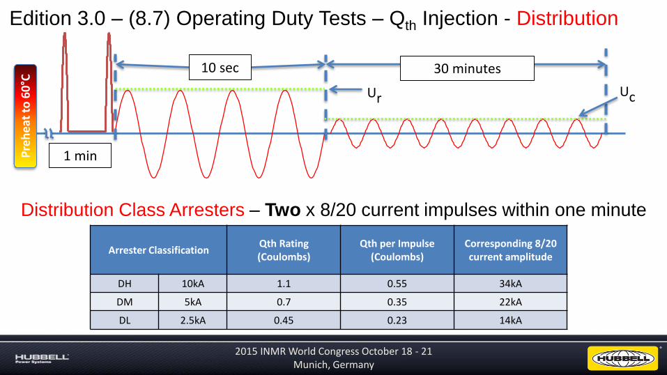
Edition 3.0 – (8.7) Operating Duty Tests – Qth Injection - Distribution
30 minutes
Pre
he
at t
o 6
0°C
10 sec
Distribution Class Arresters – Two x 8/20 current impulses within one minute
Arrester ClassificationQth Rating(Coulombs)
Qth per Impulse(Coulombs)
Corresponding 8/20 current amplitude
DH 10kA 1.1 0.55 34kA
DM 5kA 0.7 0.35 22kA
DL 2.5kA 0.45 0.23 14kA
1 min
Ur Uc
2015 INMR World Congress October 18 - 21 Munich, Germany
®
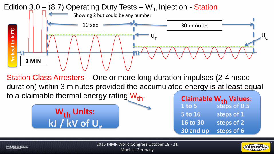
Edition 3.0 – (8.7) Operating Duty Tests – Wth Injection - Station
30 minutes
Pre
he
at t
o 6
0°C
10 sec
Station Class Arresters – One or more long duration impulses (2-4 msec
duration) within 3 minutes provided the accumulated energy is at least equal
to a claimable thermal energy rating Wth.
3 MIN
Claimable Wth Values:1 to 5 steps of 0.55 to 16 steps of 116 to 30 steps of 230 and up steps of 6
Wth Units:
kJ / kV of Ur
Ur Uc
Showing 2 but could be any number
2015 INMR World Congress October 18 - 21 Munich, Germany

®
Edition 3.0 – (8.8) Power-frequency (TOV) Voltage Versus Time Test
“Prior Duty” Test requires injection of Qth or
Wth energy exactly like operating duty test.
Four tests, One in each range = 4 data points.
TOV Required Time Ranges
(Seconds)
Range 1 0.1 to 1.0
Range 2 1.1 to 10
Range 3 10.1 to 100
Range 4 101 to 3,600
Duration per Chart
Pre
he
at t
o 6
0°C
Uc for 30 minutes
“Without Prior Duty” Test has no impulses
prior to start of TOV time period. Two tests, One from two ranges = 2 data points
This voltage is what is plotted
Station rectangular waves shown. If DH these would be 8/20
2015 INMR World Congress October 18 - 21 Munich, Germany

®
Edition 2.2 – (8.6) Arrester Disconnector Tests
Edition 3.0 – (8.9) Arrester Disconnector Tests
• Withstand without operating:
• Long-duration current impulse test
• Operating duty test
• Time versus current curve test
• 20A, 200A, 800A
• Withstand without operating:
• Repetitive Charge transfer test - Qrs
• Operating duty test – Wth or Qth
• Time versus current curve test
• 20A, 200A, 800A
• Bending moment, tensile load and torsional load tests
• Temperature cycling and seal pumping tests
Added
2015 INMR World Congress October 18 - 21 Munich, Germany
®
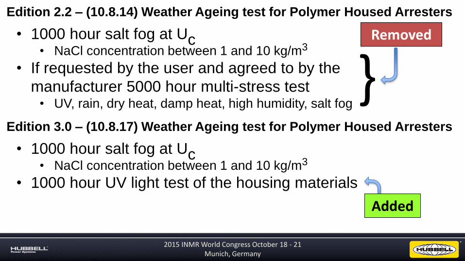
Edition 2.2 – (10.8.14) Weather Ageing test for Polymer Housed Arresters
• 1000 hour salt fog at Uc• NaCl concentration between 1 and 10 kg/m3
• If requested by the user and agreed to by the
manufacturer 5000 hour multi-stress test• UV, rain, dry heat, damp heat, high humidity, salt fog
Edition 3.0 – (10.8.17) Weather Ageing test for Polymer Housed Arresters
• 1000 hour salt fog at Uc• NaCl concentration between 1 and 10 kg/m3
• 1000 hour UV light test of the housing materials
Removed
Added
}
2015 INMR World Congress October 18 - 21 Munich, Germany
®
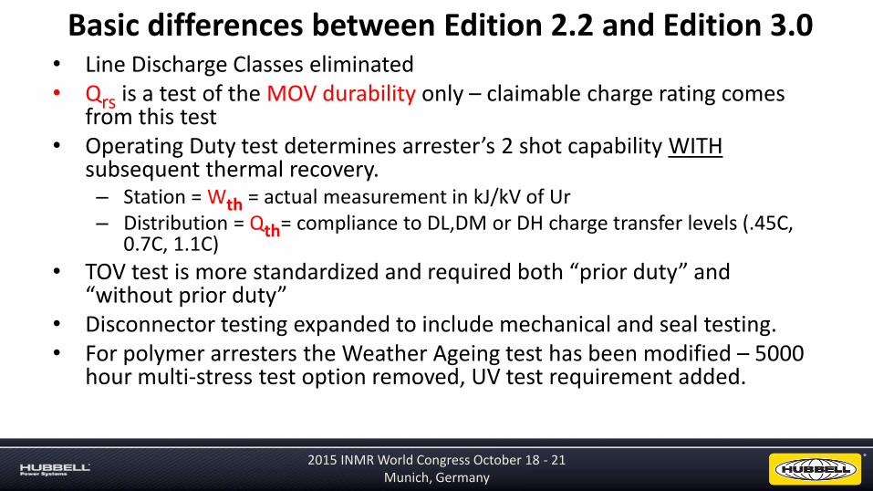
• Line Discharge Classes eliminated• Qrs is a test of the MOV durability only – claimable charge rating comes
from this test• Operating Duty test determines arrester’s 2 shot capability WITH
subsequent thermal recovery.– Station = Wth = actual measurement in kJ/kV of Ur– Distribution = Qth= compliance to DL,DM or DH charge transfer levels (.45C,
0.7C, 1.1C)
• TOV test is more standardized and required both “prior duty” and “without prior duty”
• Disconnector testing expanded to include mechanical and seal testing.• For polymer arresters the Weather Ageing test has been modified – 5000
hour multi-stress test option removed, UV test requirement added.
Basic differences between Edition 2.2 and Edition 3.0
2015 INMR World Congress October 18 - 21 Munich, Germany