analysis of optimization in an otec plant using organic ... · pdf fileanalysis of...
TRANSCRIPT
lable at ScienceDirect
Renewable Energy 68 (2014) 25e34
Contents lists avai
Renewable Energy
journal homepage: www.elsevier .com/locate/renene
Analysis of optimization in an OTEC plant using organic Rankine cycle
Min-Hsiung Yang a,*, Rong-Hua Yeh b
aDepartment of Naval Architecture and Ocean Engineering, National Kaohsiung Marine University, Taiwan, ROCbDepartment of Marine Engineering, National Kaohsiung Marine University, Taiwan, ROC
a r t i c l e i n f o
Article history:Received 29 August 2013Accepted 26 January 2014Available online 16 February 2014
Keywords:OTECORCOptimalEvaporationCondensationPerformance
* Corresponding author. No.142, Haizhuan Rd., NanzTaiwan, ROC. Tel.: þ886 7 3617141x3404; fax: þ886 7
E-mail address: [email protected] (M
0960-1481/$ e see front matter � 2014 Elsevier Ltd.http://dx.doi.org/10.1016/j.renene.2014.01.029
a b s t r a c t
This study quantified the effects of evaporation temperature, condensation temperature, and the inlet-and outlet-temperature differences of deep cold seawater and warm seawater on the performance of anocean thermal energy conversion (OTEC) plant using an organic Rankine cycle (ORC), and also investi-gated the optimal operations required for the performance. A finite-temperature-difference heat transfermethod is developed to evaluate the objective parameter, which is the ratio of net power output to thetotal heat transfer area of heat exchanger in the system, and R717, R600a, R245fa, R152a, and R134a wereused as the working fluids. The optimal evaporation and condensation temperatures were obtainedunder various conditions for maximal objective parameters in an OTEC system.
The results show that R717 performed optimally in objective parameter evaluation among the fiveworking fluids, and that R600a performed better than other fluids in thermal efficiency analysis. Theoptimal seawater temperature differences between the inlet and outlet of the evaporator and condenserare proposed. Furthermore, the influences of inlet temperatures of warm and cold seawater in the ORCare presented for an OTEC plant. The simulation results should enable the performance of an ORC systemto be compared when using various organic working fluids.
� 2014 Elsevier Ltd. All rights reserved.
1. Introduction
Saving energy and reducing carbon dioxide emissions havebecome increasingly critical aspects of energy usage because ofconcerns regarding energy shortage, global warming, and envi-ronmental pollution. Thus, researchers have extensively investi-gated approaches to use renewable and sustainable energy sourceseffectively. The ocean thermal energy conversion (OTEC) processuses the disparity in temperature between the warm seawater onthe ocean surface and the deep cold seawater to operate a Rankinecycle system for producing electrical power without consumingfuel or emitting carbon [1e3]. Although using ocean thermal en-ergy has enormous potential and the OTEC plants have a smallenvironment impact, the low net efficiency of OTEC resulting fromthe lower temperature differences between surface seawater andcold seawater restricts the implementation of this technology [4].
To improve the thermal efficiency of OTEC, suitable workingfluids for use in the Rankine cycle must be identified. Ammonia,which is named R717, was used in the OTEC system widely in thepast because of its excellent thermodynamic properties. Uehara
i Dist., Kaohsiung City 81157,3656481..-H. Yang).
All rights reserved.
et al. [5,6] investigated the major components of an OTEC planttheoretically and experimentally. In their simulation results, thetemperatures of warm and cold seawater were 26 �C and 4 �C,respectively, for optimizing a 100-MW OTEC system. Uehara et al.also reported that R717 was one of the suitable working fluids for aclosed-Rankine-cycle OTEC plant. Using R717 as the working fluid,Yeh et al. [7] studied theoretically the effects of temperature andflow rate of cold seawater on the net output of an OTEC plant. Theyconcluded that the network has a maximal output at a specific coldseawater flow rate.
To improve efficiency and to reduce system costs, the organicRankine cycle (ORC) is used with working liquids that have a lowboiling temperature. To identify suitable working fluids for an ORC,Chen et al. [8] and Wang et al. [9] investigated the thermodynamicperformances of ORC by using various working fluids to convertlow-grade heat. Sun et al. [10] optimized numerically the design foran ORC in OTEC with R717 and R134a. The exergy-analysis modewas used to evaluate the maximal net output under various warmwater mass-flow rates and evaporation temperatures. However, inthe calculation, the overall heat transfer coefficient remained un-changed and the work consumed in pumping seawater wasneglected. From the first law of thermodynamics, a high heat-source temperature would increase the pressure and enthalpy ofthe working fluid at the turbine inlet. To increase the thermal ef-ficiency of the OTEC system, solar heat energy [11,12] and the waste
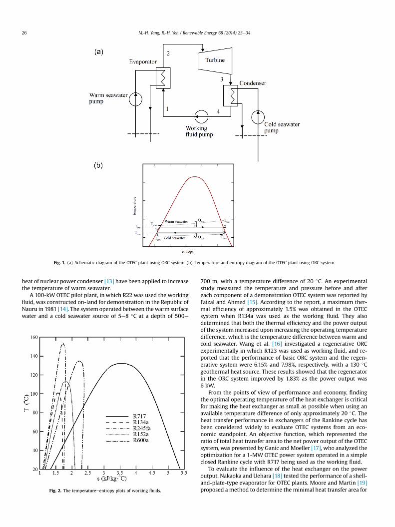
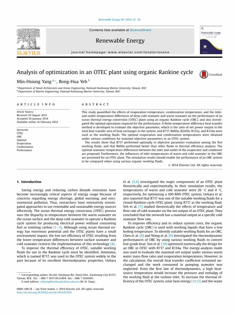
Fig. 1. (a). Schematic diagram of the OTEC plant using ORC system. (b). Temperature and entropy diagram of the OTEC plant using ORC system.
M.-H. Yang, R.-H. Yeh / Renewable Energy 68 (2014) 25e3426
heat of nuclear power condenser [13] have been applied to increasethe temperature of warm seawater.
A 100-kW OTEC pilot plant, in which R22 was used the workingfluid, was constructed on-land for demonstration in the Republic ofNauru in 1981 [14]. The system operated between thewarm surfacewater and a cold seawater source of 5e8 �C at a depth of 500e
Fig. 2. The temperatureeentropy plots of working fluids.
700 m, with a temperature difference of 20 �C. An experimentalstudy measured the temperature and pressure before and aftereach component of a demonstration OTEC system was reported byFaizal and Ahmed [15]. According to the report, a maximum ther-mal efficiency of approximately 1.5% was obtained in the OTECsystem when R134a was used as the working fluid. They alsodetermined that both the thermal efficiency and the power outputof the system increased upon increasing the operating temperaturedifference, which is the temperature difference betweenwarm andcold seawater. Wang et al. [16] investigated a regenerative ORCexperimentally in which R123 was used as working fluid, and re-ported that the performance of basic ORC system and the regen-erative system were 6.15% and 7.98%, respectively, with a 130 �Cgeothermal heat source. These results showed that the regeneratorin the ORC system improved by 1.83% as the power output was6 kW.
From the points of view of performance and economy, findingthe optimal operating temperature of the heat exchanger is criticalfor making the heat exchanger as small as possible when using anavailable temperature difference of only approximately 20 �C. Theheat transfer performance in exchangers of the Rankine cycle hasbeen considered widely to evaluate OTEC systems from an eco-nomic standpoint. An objective function, which represented theratio of total heat transfer area to the net power output of the OTECsystem, was presented by Ganic andMoeller [17], who analyzed theoptimization for a 1-MW OTEC power system operated in a simpleclosed Rankine cycle with R717 being used as the working fluid.
To evaluate the influence of the heat exchanger on the poweroutput, Nakaoka and Uehara [18] tested the performance of a shell-and-plate-type evaporator for OTEC plants. Moore and Martin [19]proposed a method to determine the minimal heat transfer area for
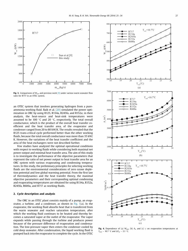
Fig. 3. Comparisons of Wver and previous work [9] under various warm seawater flowrates for R717 in an OTEC system.
M.-H. Yang, R.-H. Yeh / Renewable Energy 68 (2014) 25e34 27
an OTEC system that involves generating hydrogen from a pure-ammonia working fluid. Baik et al. [20] simulated the power opti-mization in ORC by using R125, R134a, R245fa, and R152a; in theiranalysis, the heat-source and heat-sink temperatures wereassumed to be 100 �C and 20 �C, respectively. The total overallconductance, which is the product of the overall heat transfer co-efficient and the heat transfer area, of the evaporator andcondenser ranged from 20 to 80 kW/K. The results revealed that theR125 trans-critical cycle performed better than the other workingfluids, because the total overall conductance was more than 35 kW/K. However, the variations of the heat transfer coefficient and thearea of the heat exchangers were not described further.
Few studies have analyzed the optimal operational conditionswith respect to working fluids while considering both maximal netpower output and minimal heat transfer area. The aim of this studyis to investigate the performance of the objective parameters thatrepresent the ratio of net power output to heat transfer area for anORC system with various evaporating and condensing tempera-tures. In this study, the preliminary principles for selecting workingfluids are the environmental considerations of zero ozone deple-tion potential and low global warming potential. From the first lawof thermodynamics and the heat transfer theory, the maximalobjective parameters and their corresponding optimal condensingand evaporating temperatures are obtained for using R134a, R152a,R245fa, R600a, and R717 as working fluids.
Fig. 4. Dependence of (a) Wnet, (b) At, and (c) g on evaporation temperatures atTcon ¼ 10.7 �C and DTw ¼ 2.1 �C.
2. Cycle description and analysis
The ORC in an OTEC plant consists mainly of a pump, an evap-orator, a turbine, and a condenser, as shown in Fig. 1(a). In theevaporator, the working fluid absorbs heat that is transferred fromthe warm seawater and reaches saturation temperature, afterwhich the working fluid continues to be heated and thereby be-comes a saturated vapor at the outlet of the evaporator. The vaporexpands while passing through the turbine and produces powerbecause of the pressure difference of evaporation and condensa-tion. The low-pressure vapor then enters the condenser cooled bycold deep seawater. After condensation, the liquid working fluid ispumped back into the evaporator to complete the cycle. In the OTEC
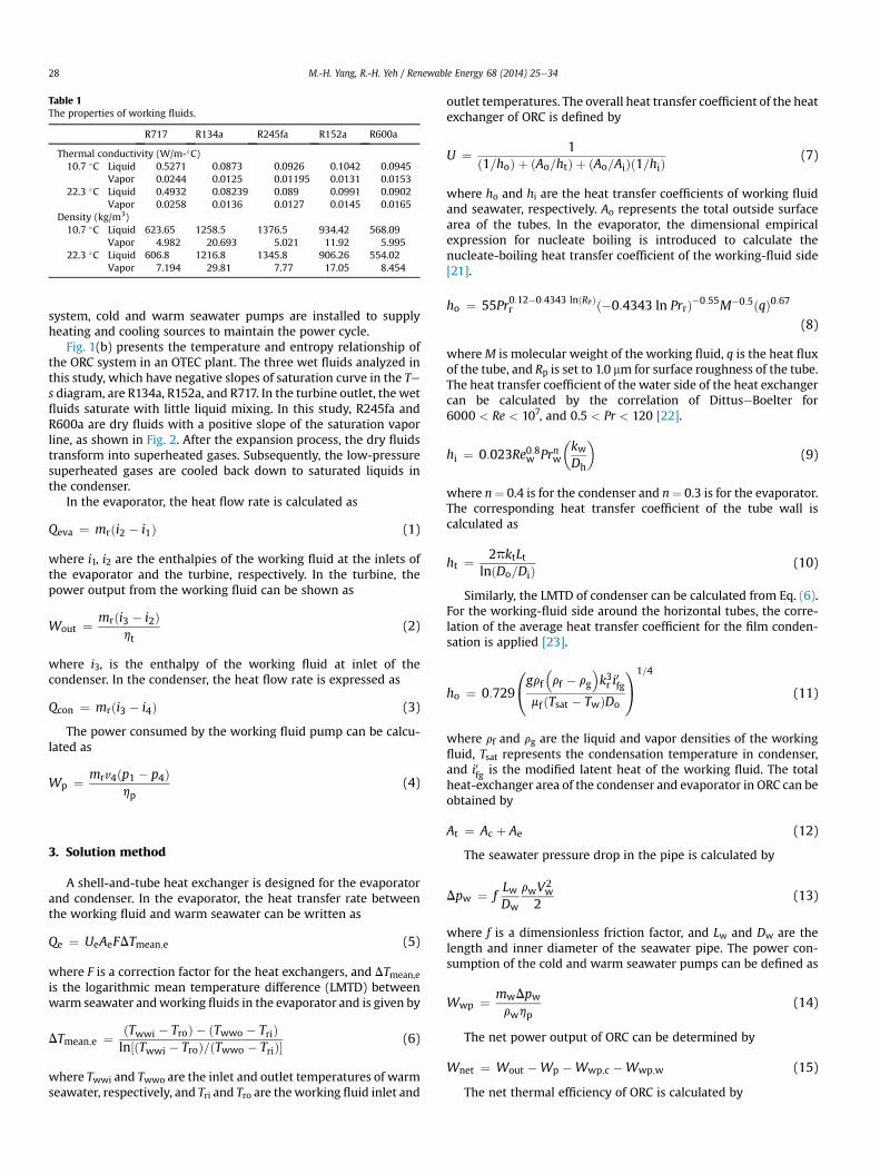
Table 1The properties of working fluids.
R717 R134a R245fa R152a R600a
Thermal conductivity (W/m-�C)10.7 �C Liquid 0.5271 0.0873 0.0926 0.1042 0.0945
Vapor 0.0244 0.0125 0.01195 0.0131 0.015322.3 �C Liquid 0.4932 0.08239 0.089 0.0991 0.0902
Vapor 0.0258 0.0136 0.0127 0.0145 0.0165Density (kg/m3)10.7 �C Liquid 623.65 1258.5 1376.5 934.42 568.09
Vapor 4.982 20.693 5.021 11.92 5.99522.3 �C Liquid 606.8 1216.8 1345.8 906.26 554.02
Vapor 7.194 29.81 7.77 17.05 8.454
M.-H. Yang, R.-H. Yeh / Renewable Energy 68 (2014) 25e3428
system, cold and warm seawater pumps are installed to supplyheating and cooling sources to maintain the power cycle.
Fig. 1(b) presents the temperature and entropy relationship ofthe ORC system in an OTEC plant. The three wet fluids analyzed inthis study, which have negative slopes of saturation curve in the Tes diagram, are R134a, R152a, and R717. In the turbine outlet, thewetfluids saturate with little liquid mixing. In this study, R245fa andR600a are dry fluids with a positive slope of the saturation vaporline, as shown in Fig. 2. After the expansion process, the dry fluidstransform into superheated gases. Subsequently, the low-pressuresuperheated gases are cooled back down to saturated liquids inthe condenser.
In the evaporator, the heat flow rate is calculated as
Qeva ¼ mrði2 � i1Þ (1)
where i1, i2 are the enthalpies of the working fluid at the inlets ofthe evaporator and the turbine, respectively. In the turbine, thepower output from the working fluid can be shown as
Wout ¼ mrði3 � i2Þht
(2)
where i3, is the enthalpy of the working fluid at inlet of thecondenser. In the condenser, the heat flow rate is expressed as
Qcon ¼ mrði3 � i4Þ (3)
The power consumed by the working fluid pump can be calcu-lated as
Wp ¼ mrv4ðp1 � p4Þhp
(4)
3. Solution method
A shell-and-tube heat exchanger is designed for the evaporatorand condenser. In the evaporator, the heat transfer rate betweenthe working fluid and warm seawater can be written as
Qe ¼ UeAeFDTmean;e (5)
where F is a correction factor for the heat exchangers, and DTmean,eis the logarithmic mean temperature difference (LMTD) betweenwarm seawater andworking fluids in the evaporator and is given by
DTmean;e ¼ ðTwwi � TroÞ � ðTwwo � TriÞln½ðTwwi � TroÞ=ðTwwo � TriÞ�
(6)
where Twwi and Twwo are the inlet and outlet temperatures of warmseawater, respectively, and Tri and Tro are theworking fluid inlet and
outlet temperatures. The overall heat transfer coefficient of the heatexchanger of ORC is defined by
U ¼ 1ð1=hoÞ þ ðAo=htÞ þ ðAo=AiÞð1=hiÞ
(7)
where ho and hi are the heat transfer coefficients of working fluidand seawater, respectively. Ao represents the total outside surfacearea of the tubes. In the evaporator, the dimensional empiricalexpression for nucleate boiling is introduced to calculate thenucleate-boiling heat transfer coefficient of the working-fluid side[21].
ho ¼ 55Pr0:12�0:4343 lnðRPÞr ð�0:4343 ln PrrÞ�0:55M�0:5ðqÞ0:67
(8)
whereM is molecular weight of the working fluid, q is the heat fluxof the tube, and Rp is set to 1.0 mm for surface roughness of the tube.The heat transfer coefficient of the water side of the heat exchangercan be calculated by the correlation of DittuseBoelter for6000 < Re < 107, and 0.5 < Pr < 120 [22].
hi ¼ 0:023Re0:8w Prnw
�kwDh
�(9)
where n¼ 0.4 is for the condenser and n¼ 0.3 is for the evaporator.The corresponding heat transfer coefficient of the tube wall iscalculated as
ht ¼ 2pktLtlnðDo=DiÞ
(10)
Similarly, the LMTD of condenser can be calculated from Eq. (6).For the working-fluid side around the horizontal tubes, the corre-lation of the average heat transfer coefficient for the film conden-sation is applied [23].
ho ¼ 0:729
0@grf
�rf � rg
�k3r i
0fg
mf ðTsat � TwÞDo
1A
1=4
(11)
where rf and rg are the liquid and vapor densities of the workingfluid, Tsat represents the condensation temperature in condenser,and i0fg is the modified latent heat of the working fluid. The totalheat-exchanger area of the condenser and evaporator in ORC can beobtained by
At ¼ Ac þ Ae (12)
The seawater pressure drop in the pipe is calculated by
Dpw ¼ fLwDw
rwV2w
2(13)
where f is a dimensionless friction factor, and Lw and Dw are thelength and inner diameter of the seawater pipe. The power con-sumption of the cold and warm seawater pumps can be defined as
Wwp ¼ mwDpwrwhp
(14)
The net power output of ORC can be determined by
Wnet ¼ Wout �Wp �Wwp;c �Wwp;w (15)
The net thermal efficiency of ORC is calculated by
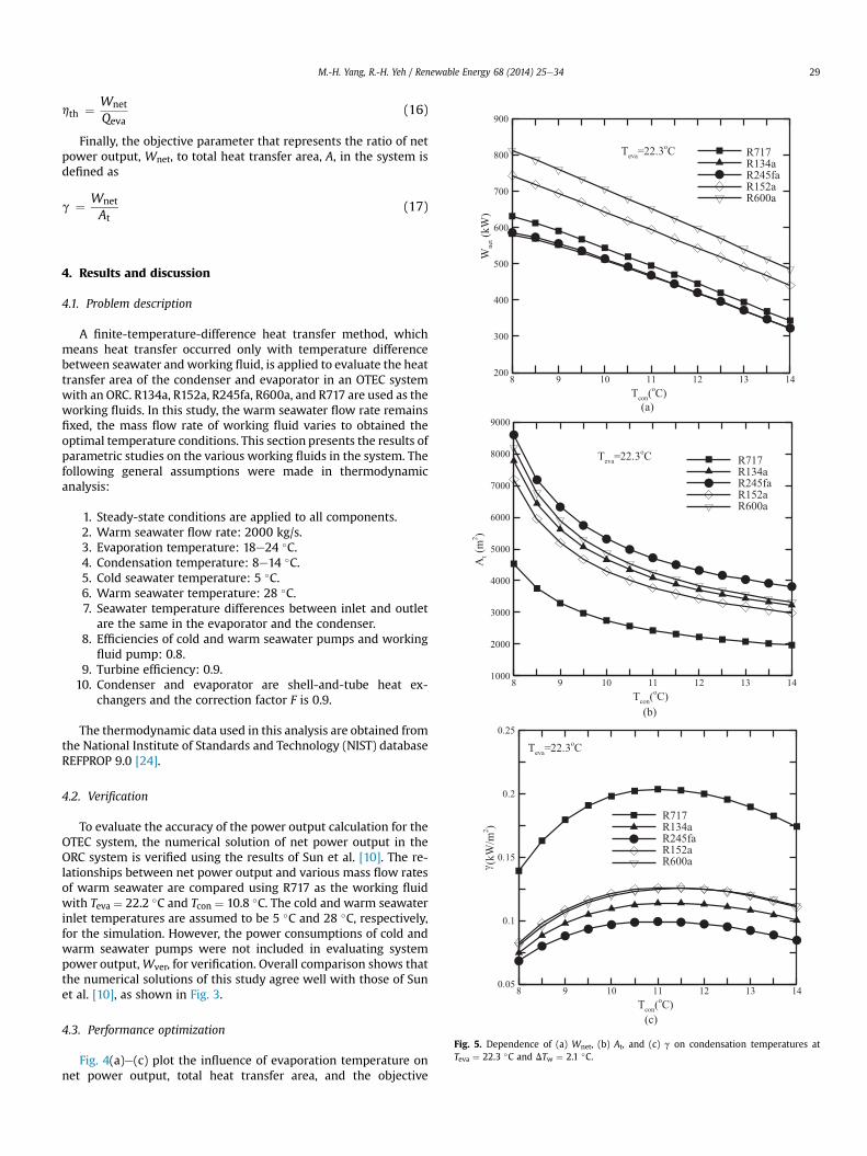
Fig. 5. Dependence of (a) Wnet, (b) At, and (c) g on condensation temperatures atTeva ¼ 22.3 �C and DTw ¼ 2.1 �C.
M.-H. Yang, R.-H. Yeh / Renewable Energy 68 (2014) 25e34 29
hth ¼ Wnet
Qeva(16)
Finally, the objective parameter that represents the ratio of netpower output, Wnet, to total heat transfer area, A, in the system isdefined as
g ¼ Wnet
At(17)
4. Results and discussion
4.1. Problem description
A finite-temperature-difference heat transfer method, whichmeans heat transfer occurred only with temperature differencebetween seawater and working fluid, is applied to evaluate the heattransfer area of the condenser and evaporator in an OTEC systemwith an ORC. R134a, R152a, R245fa, R600a, and R717 are used as theworking fluids. In this study, the warm seawater flow rate remainsfixed, the mass flow rate of working fluid varies to obtained theoptimal temperature conditions. This section presents the results ofparametric studies on the various working fluids in the system. Thefollowing general assumptions were made in thermodynamicanalysis:
1. Steady-state conditions are applied to all components.2. Warm seawater flow rate: 2000 kg/s.3. Evaporation temperature: 18e24 �C.4. Condensation temperature: 8e14 �C.5. Cold seawater temperature: 5 �C.6. Warm seawater temperature: 28 �C.7. Seawater temperature differences between inlet and outlet
are the same in the evaporator and the condenser.8. Efficiencies of cold and warm seawater pumps and working
fluid pump: 0.8.9. Turbine efficiency: 0.9.
10. Condenser and evaporator are shell-and-tube heat ex-changers and the correction factor F is 0.9.
The thermodynamic data used in this analysis are obtained fromthe National Institute of Standards and Technology (NIST) databaseREFPROP 9.0 [24].
4.2. Verification
To evaluate the accuracy of the power output calculation for theOTEC system, the numerical solution of net power output in theORC system is verified using the results of Sun et al. [10]. The re-lationships between net power output and various mass flow ratesof warm seawater are compared using R717 as the working fluidwith Teva ¼ 22.2 �C and Tcon ¼ 10.8 �C. The cold and warm seawaterinlet temperatures are assumed to be 5 �C and 28 �C, respectively,for the simulation. However, the power consumptions of cold andwarm seawater pumps were not included in evaluating systempower output,Wver, for verification. Overall comparison shows thatthe numerical solutions of this study agree well with those of Sunet al. [10], as shown in Fig. 3.
4.3. Performance optimization
Fig. 4(a)e(c) plot the influence of evaporation temperature onnet power output, total heat transfer area, and the objective
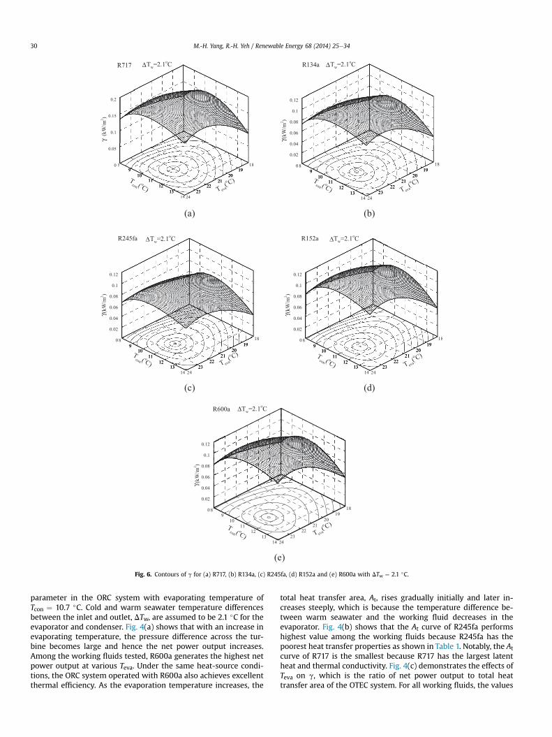
Fig. 6. Contours of g for (a) R717, (b) R134a, (c) R245fa, (d) R152a and (e) R600a with DTw ¼ 2.1 �C.
M.-H. Yang, R.-H. Yeh / Renewable Energy 68 (2014) 25e3430
parameter in the ORC system with evaporating temperature ofTcon ¼ 10.7 �C. Cold and warm seawater temperature differencesbetween the inlet and outlet, DTw, are assumed to be 2.1 �C for theevaporator and condenser. Fig. 4(a) shows that with an increase inevaporating temperature, the pressure difference across the tur-bine becomes large and hence the net power output increases.Among the working fluids tested, R600a generates the highest netpower output at various Teva. Under the same heat-source condi-tions, the ORC system operated with R600a also achieves excellentthermal efficiency. As the evaporation temperature increases, the
total heat transfer area, At, rises gradually initially and later in-creases steeply, which is because the temperature difference be-tween warm seawater and the working fluid decreases in theevaporator. Fig. 4(b) shows that the At curve of R245fa performshighest value among the working fluids because R245fa has thepoorest heat transfer properties as shown in Table 1. Notably, the At
curve of R717 is the smallest because R717 has the largest latentheat and thermal conductivity. Fig. 4(c) demonstrates the effects ofTeva on g, which is the ratio of net power output to total heattransfer area of the OTEC system. For all working fluids, the values
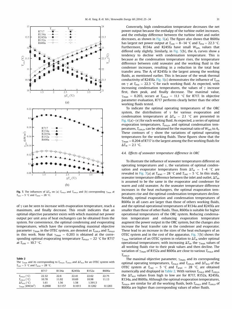
Fig. 7. The influences of DTw on (a) Teva,o and Tcon,o and (b) corresponding gmax atTwci ¼ 5 �C and Twwi ¼ 28 �C.
M.-H. Yang, R.-H. Yeh / Renewable Energy 68 (2014) 25e34 31
of g can be seen to increase with evaporation temperature, reach amaximum, and finally decrease. This result indicates that anoptimal objective parameter exists with which maximal net poweroutput per unit area of heat exchangers can be obtained from thesystem. For convenience, the optimal condensing and evaporatingtemperatures, which have the corresponding maximal objectiveparameter gmax in the OTEC system, are denoted as Tcon,o and Teva,oin this work. Note that gmax ¼ 0.203 is obtained at the corre-sponding optimal evaporating temperature Teva,o ¼ 22 �C for R717at Tcon ¼ 10.7 �C.
Table 2The gmax and its corresponding to Teva,o, Tcon,o and DTw,o for an OTEC system withTcwi ¼ 5 �C and Twwi ¼ 28 �C.
R717 R134a R245fa R152a R600a
Teva,o (�C) 22.32 22.6 22.41 22.62 22.75Tcon,o (�C) 10.78 11.02 10.69 10.98 11.13DTw,o (�C) 1.61 1.56 1.58 1.591.5gmax (kW/m2) 0.2068 0.1157 0.1011 0.1282 0.1283
Conversely, high condensation temperature decreases the netpower output because the enthalpy of the turbine outlet increases,and the enthalpy difference between the turbine inlet and outletdecreases, as shown in Fig. 5(a). The figure also shows that R600ahas largest net power output at Tcon ¼ 8e14 �C and Teva ¼ 22.3 �C.Furthermore, R134a and R245fa have small Wnet, values thatdiffered only slightly. Similarly, in Fig. 5(b), the At curves show atendency to decline with condensation temperature. This isbecause as the condensation temperature rises, the temperaturedifference between cold seawater and the working fluid in thecondenser increases, resulting in a reduction in the total heattransfer area. The At of R245fa is the largest among the workingfluids, as mentioned earlier. This is because of the weak thermalconductivity of R245fa. Fig. 5(c) demonstrates the influence of Tconon g at Teva ¼ 22.3 �C for each working fluid. As expected, withincreasing condensation temperatures, the values of g increasefirst, then peak, and finally decrease. The maximal value,gmax ¼ 0.203, occurs at Tcon,o ¼ 11.1 �C for R717. In objectiveparameter evaluation, R717 performs clearly better than the otherworking fluids tested.
To indicate the optimal operating temperatures of the ORCsystem, the distributions of g for various evaporation andcondensation temperatures at DTw ¼ 2.1 �C are presented inFig. 6(a)e(e) for each working fluid. As expected, a series of optimalevaporation temperatures, Teva,o, and optimal condensation tem-peratures, Tcon,o, can be obtained for the maximal ratio ofWnet to At.These contours of g show the variations of optimal operatingtemperatures for the working fluids. These figures show that thegmax¼ 0.204 of R717 is the largest among the fiveworking fluids forDTw ¼ 2.1 �C.
4.4. Effects of seawater temperature difference in ORC
To illustrate the influence of seawater temperatures different onoperating temperatures and g, the variations of optimal conden-sation and evaporator temperatures from DTw ¼ 1e4 �C arerevealed in Fig. 7(a) at Twwi ¼ 28 �C and Tcwi ¼ 5 �C. In this study,seawater temperature difference between the inlet and outlet, DTw,is assumed to be the same in the evaporator and condenser forwarm and cold seawater. As the seawater temperature differenceincreases in the heat exchangers, the optimal evaporation tem-peratures rise and the optimal condensation temperatures decline.Notably, optimal evaporation and condensation temperatures ofR600a in all cases are larger than those of others working fluids,and the optimal operational temperatures of R134a and R245fa aresmaller than those of other fluids. Thus, R600a is suitable for higheroperational temperatures of the ORC system. Reducing condensa-tion temperature and enhancing evaporation temperatureaugment the power output in the ORC system, but the changes alsoincrease the heat transfer rate in the condenser and evaporator.These lead to an increase in the sizes of the heat exchangers of anOTEC system and in the cost of the apparatus. Fig. 7(b) shows thegmax variation of an OTEC system in relation to DTw under optimaloperational temperatures; with increasing DTw, the gmax values ofall working fluids rise to their peak values and then decline. Thevariation of gmax of R152a and R600a are close to various Teva,o andTcon,o.
The maximal objective parameter, gmax, and its correspondingoptimal operating temperatures, Teva,o and Tcon,o, and DTw,o of theOTEC system at Tcwi ¼ 5 �C and Twwi ¼ 28 �C, are obtainednumerically and displayed in Table 2. With various Teva,o and Tcon,o,the DTw,o values from high to low are for R717, R152a, R245fa,R134a, and R600a. Although the optimal evaporation temperatures,Teva,o, are similar for all the working fluids, both Teva,o and Tcon,o ofR600a are higher than corresponding values of other fluids.
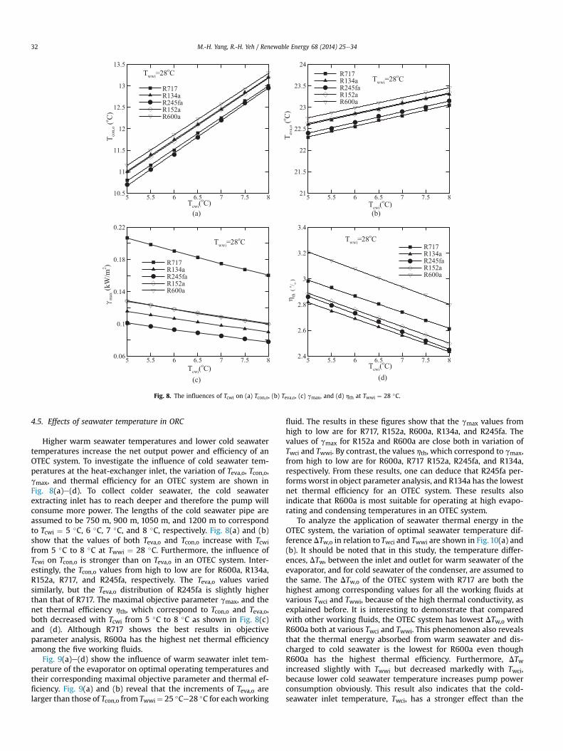
Fig. 8. The influences of Tcwi on (a) Tcon,o, (b) Teva,o, (c) gmax, and (d) hth at Twwi ¼ 28 �C.
M.-H. Yang, R.-H. Yeh / Renewable Energy 68 (2014) 25e3432
4.5. Effects of seawater temperature in ORC
Higher warm seawater temperatures and lower cold seawatertemperatures increase the net output power and efficiency of anOTEC system. To investigate the influence of cold seawater tem-peratures at the heat-exchanger inlet, the variation of Teva,o, Tcon,o,gmax, and thermal efficiency for an OTEC system are shown inFig. 8(a)e(d). To collect colder seawater, the cold seawaterextracting inlet has to reach deeper and therefore the pump willconsume more power. The lengths of the cold seawater pipe areassumed to be 750 m, 900 m, 1050 m, and 1200 m to correspondto Tcwi ¼ 5 �C, 6 �C, 7 �C, and 8 �C, respectively. Fig. 8(a) and (b)show that the values of both Teva,o and Tcon,o increase with Tcwifrom 5 �C to 8 �C at Twwi ¼ 28 �C. Furthermore, the influence ofTcwi on Tcon,o is stronger than on Teva,o in an OTEC system. Inter-estingly, the Tcon,o values from high to low are for R600a, R134a,R152a, R717, and R245fa, respectively. The Teva,o values variedsimilarly, but the Teva,o distribution of R245fa is slightly higherthan that of R717. The maximal objective parameter gmax, and thenet thermal efficiency hth, which correspond to Tcon,o and Teva,o,both decreased with Tcwi from 5 �C to 8 �C as shown in Fig. 8(c)and (d). Although R717 shows the best results in objectiveparameter analysis, R600a has the highest net thermal efficiencyamong the five working fluids.
Fig. 9(a)e(d) show the influence of warm seawater inlet tem-perature of the evaporator on optimal operating temperatures andtheir corresponding maximal objective parameter and thermal ef-ficiency. Fig. 9(a) and (b) reveal that the increments of Teva,o arelarger than those of Tcon,o from Twwi¼ 25 �Ce28 �C for eachworking
fluid. The results in these figures show that the gmax values fromhigh to low are for R717, R152a, R600a, R134a, and R245fa. Thevalues of gmax for R152a and R600a are close both in variation ofTwci and Twwi. By contrast, the values hth, which correspond to gmax,from high to low are for R600a, R717 R152a, R245fa, and R134a,respectively. From these results, one can deduce that R245fa per-forms worst in object parameter analysis, and R134a has the lowestnet thermal efficiency for an OTEC system. These results alsoindicate that R600a is most suitable for operating at high evapo-rating and condensing temperatures in an OTEC system.
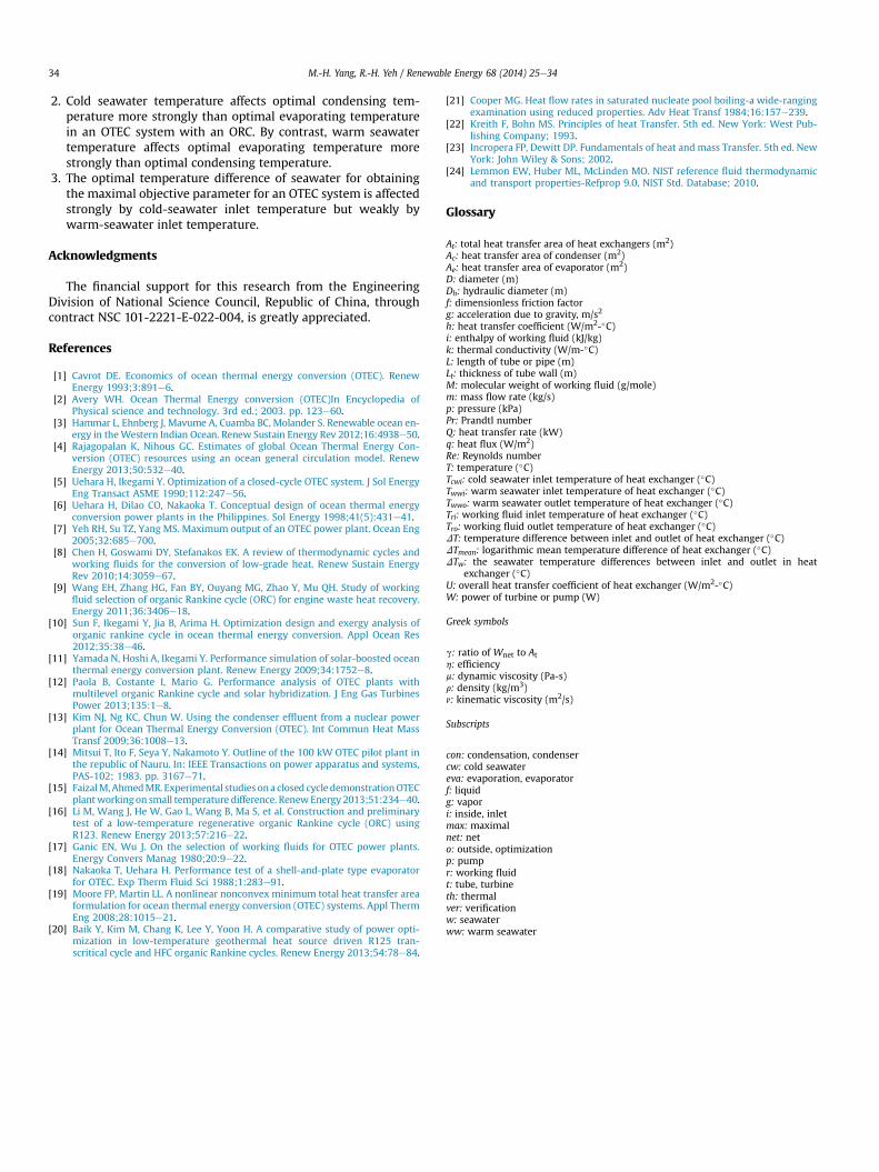
To analyze the application of seawater thermal energy in theOTEC system, the variation of optimal seawater temperature dif-ference DTw,o in relation to Twci and Twwi are shown in Fig. 10(a) and(b). It should be noted that in this study, the temperature differ-ences, DTw, between the inlet and outlet for warm seawater of theevaporator, and for cold seawater of the condenser, are assumed tothe same. The DTw,o of the OTEC system with R717 are both thehighest among corresponding values for all the working fluids atvarious Twci and Twwi, because of the high thermal conductivity, asexplained before. It is interesting to demonstrate that comparedwith other working fluids, the OTEC system has lowest DTw,o withR600a both at various Twci and Twwi. This phenomenon also revealsthat the thermal energy absorbed from warm seawater and dis-charged to cold seawater is the lowest for R600a even thoughR600a has the highest thermal efficiency. Furthermore, DTwincreased slightly with Twwi but decreased markedly with Twci,because lower cold seawater temperature increases pump powerconsumption obviously. This result also indicates that the cold-seawater inlet temperature, Twci, has a stronger effect than the
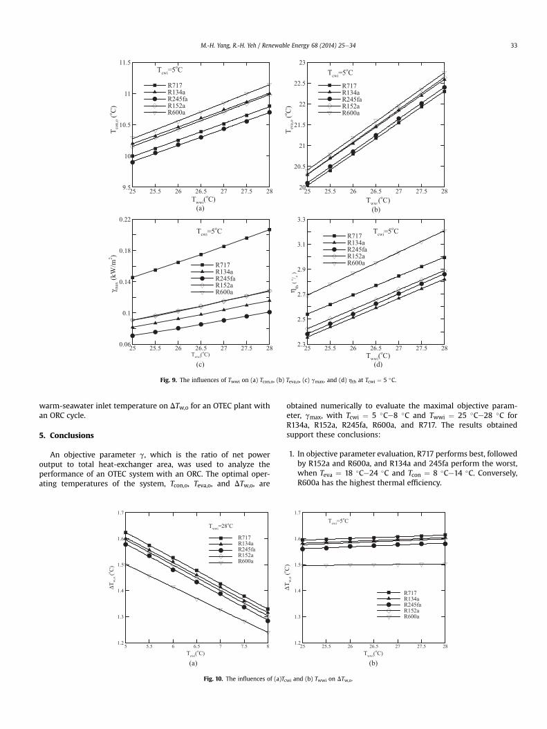
Fig. 9. The influences of Twwi on (a) Tcon,o, (b) Teva,o, (c) gmax, and (d) hth at Tcwi ¼ 5 �C.
M.-H. Yang, R.-H. Yeh / Renewable Energy 68 (2014) 25e34 33
warm-seawater inlet temperature on DTw,o for an OTEC plant withan ORC cycle.
5. Conclusions
An objective parameter g, which is the ratio of net poweroutput to total heat-exchanger area, was used to analyze theperformance of an OTEC system with an ORC. The optimal oper-ating temperatures of the system, Tcon,o, Teva,o, and DTw,o, are
Fig. 10. The influences of (a)Tc
obtained numerically to evaluate the maximal objective param-eter, gmax, with Tcwi ¼ 5 �Ce8 �C and Twwi ¼ 25 �Ce28 �C forR134a, R152a, R245fa, R600a, and R717. The results obtainedsupport these conclusions:
1. In objective parameter evaluation, R717 performs best, followedby R152a and R600a, and R134a and 245fa perform the worst,when Teva ¼ 18 �Ce24 �C and Tcon ¼ 8 �Ce14 �C. Conversely,R600a has the highest thermal efficiency.
wi and (b) Twwi on DTw,o.
M.-H. Yang, R.-H. Yeh / Renewable Energy 68 (2014) 25e3434
2. Cold seawater temperature affects optimal condensing tem-perature more strongly than optimal evaporating temperaturein an OTEC system with an ORC. By contrast, warm seawatertemperature affects optimal evaporating temperature morestrongly than optimal condensing temperature.
3. The optimal temperature difference of seawater for obtainingthe maximal objective parameter for an OTEC system is affectedstrongly by cold-seawater inlet temperature but weakly bywarm-seawater inlet temperature.
Acknowledgments
The financial support for this research from the EngineeringDivision of National Science Council, Republic of China, throughcontract NSC 101-2221-E-022-004, is greatly appreciated.
References
[1] Cavrot DE. Economics of ocean thermal energy conversion (OTEC). RenewEnergy 1993;3:891e6.
[2] Avery WH. Ocean Thermal Energy conversion (OTEC)In Encyclopedia ofPhysical science and technology. 3rd ed.; 2003. pp. 123e60.
[3] Hammar L, Ehnberg J, Mavume A, Cuamba BC, Molander S. Renewable ocean en-ergy in theWestern Indian Ocean. Renew Sustain Energy Rev 2012;16:4938e50.
[4] Rajagopalan K, Nihous GC. Estimates of global Ocean Thermal Energy Con-version (OTEC) resources using an ocean general circulation model. RenewEnergy 2013;50:532e40.
[5] Uehara H, Ikegami Y. Optimization of a closed-cycle OTEC system. J Sol EnergyEng Transact ASME 1990;112:247e56.
[6] Uehara H, Dilao CO, Nakaoka T. Conceptual design of ocean thermal energyconversion power plants in the Philippines. Sol Energy 1998;41(5):431e41.
[7] Yeh RH, Su TZ, Yang MS. Maximum output of an OTEC power plant. Ocean Eng2005;32:685e700.
[8] Chen H, Goswami DY, Stefanakos EK. A review of thermodynamic cycles andworking fluids for the conversion of low-grade heat. Renew Sustain EnergyRev 2010;14:3059e67.
[9] Wang EH, Zhang HG, Fan BY, Ouyang MG, Zhao Y, Mu QH. Study of workingfluid selection of organic Rankine cycle (ORC) for engine waste heat recovery.Energy 2011;36:3406e18.
[10] Sun F, Ikegami Y, Jia B, Arima H. Optimization design and exergy analysis oforganic rankine cycle in ocean thermal energy conversion. Appl Ocean Res2012;35:38e46.
[11] Yamada N, Hoshi A, Ikegami Y. Performance simulation of solar-boosted oceanthermal energy conversion plant. Renew Energy 2009;34:1752e8.
[12] Paola B, Costante I, Mario G. Performance analysis of OTEC plants withmultilevel organic Rankine cycle and solar hybridization. J Eng Gas TurbinesPower 2013;135:1e8.
[13] Kim NJ, Ng KC, Chun W. Using the condenser effluent from a nuclear powerplant for Ocean Thermal Energy Conversion (OTEC). Int Commun Heat MassTransf 2009;36:1008e13.
[14] Mitsui T, Ito F, Seya Y, Nakamoto Y. Outline of the 100 kW OTEC pilot plant inthe republic of Nauru. In: IEEE Transactions on power apparatus and systems,PAS-102; 1983. pp. 3167e71.
[15] FaizalM,AhmedMR. Experimental studies ona closed cycle demonstrationOTECplantworkingon small temperature difference. RenewEnergy 2013;51:234e40.
[16] Li M, Wang J, He W, Gao L, Wang B, Ma S, et al. Construction and preliminarytest of a low-temperature regenerative organic Rankine cycle (ORC) usingR123. Renew Energy 2013;57:216e22.
[17] Ganic EN, Wu J. On the selection of working fluids for OTEC power plants.Energy Convers Manag 1980;20:9e22.
[18] Nakaoka T, Uehara H. Performance test of a shell-and-plate type evaporatorfor OTEC. Exp Therm Fluid Sci 1988;1:283e91.
[19] Moore FP, Martin LL. A nonlinear nonconvex minimum total heat transfer areaformulation for ocean thermal energy conversion (OTEC) systems. Appl ThermEng 2008;28:1015e21.
[20] Baik Y, Kim M, Chang K, Lee Y, Yoon H. A comparative study of power opti-mization in low-temperature geothermal heat source driven R125 tran-scritical cycle and HFC organic Rankine cycles. Renew Energy 2013;54:78e84.
[21] Cooper MG. Heat flow rates in saturated nucleate pool boiling-a wide-rangingexamination using reduced properties. Adv Heat Transf 1984;16:157e239.
[22] Kreith F, Bohn MS. Principles of heat Transfer. 5th ed. New York: West Pub-lishing Company; 1993.
[23] Incropera FP, Dewitt DP. Fundamentals of heat and mass Transfer. 5th ed. NewYork: John Wiley & Sons; 2002.
[24] Lemmon EW, Huber ML, McLinden MO. NIST reference fluid thermodynamicand transport properties-Refprop 9.0, NIST Std. Database; 2010.
Glossary
At: total heat transfer area of heat exchangers (m2)Ac: heat transfer area of condenser (m2)Ae: heat transfer area of evaporator (m2)D: diameter (m)Dh: hydraulic diameter (m)f: dimensionless friction factorg: acceleration due to gravity, m/s2
h: heat transfer coefficient (W/m2-�C)i: enthalpy of working fluid (kJ/kg)k: thermal conductivity (W/m-�C)L: length of tube or pipe (m)Lt: thickness of tube wall (m)M: molecular weight of working fluid (g/mole)m: mass flow rate (kg/s)p: pressure (kPa)Pr: Prandtl numberQ: heat transfer rate (kW)q: heat flux (W/m2)Re: Reynolds numberT: temperature (�C)Tcwi: cold seawater inlet temperature of heat exchanger (�C)Twwi: warm seawater inlet temperature of heat exchanger (�C)Twwo: warm seawater outlet temperature of heat exchanger (�C)Tri: working fluid inlet temperature of heat exchanger (�C)Tro: working fluid outlet temperature of heat exchanger (�C)DT: temperature difference between inlet and outlet of heat exchanger (�C)DTmean: logarithmic mean temperature difference of heat exchanger (�C)DTw: the seawater temperature differences between inlet and outlet in heat
exchanger (�C)U: overall heat transfer coefficient of heat exchanger (W/m2-�C)W: power of turbine or pump (W)
Greek symbols
g: ratio of Wnet to Ath: efficiencym: dynamic viscosity (Pa-s)r: density (kg/m3)n: kinematic viscosity (m2/s)
Subscripts
con: condensation, condensercw: cold seawatereva: evaporation, evaporatorf: liquidg: vapori: inside, inletmax: maximalnet: neto: outside, optimizationp: pumpr: working fluidt: tube, turbineth: thermalver: verificationw: seawaterww: warm seawater