analysis of passive circuits - meam.design
TRANSCRIPT

Analysisof
Passive Circuits

Kirchoff ’s Voltage LawThe sum of the voltage changes in a loop must equal zero.
Kirchoff ’s Current LawThe sum of the currents flowing into and out of a node must equal zero.
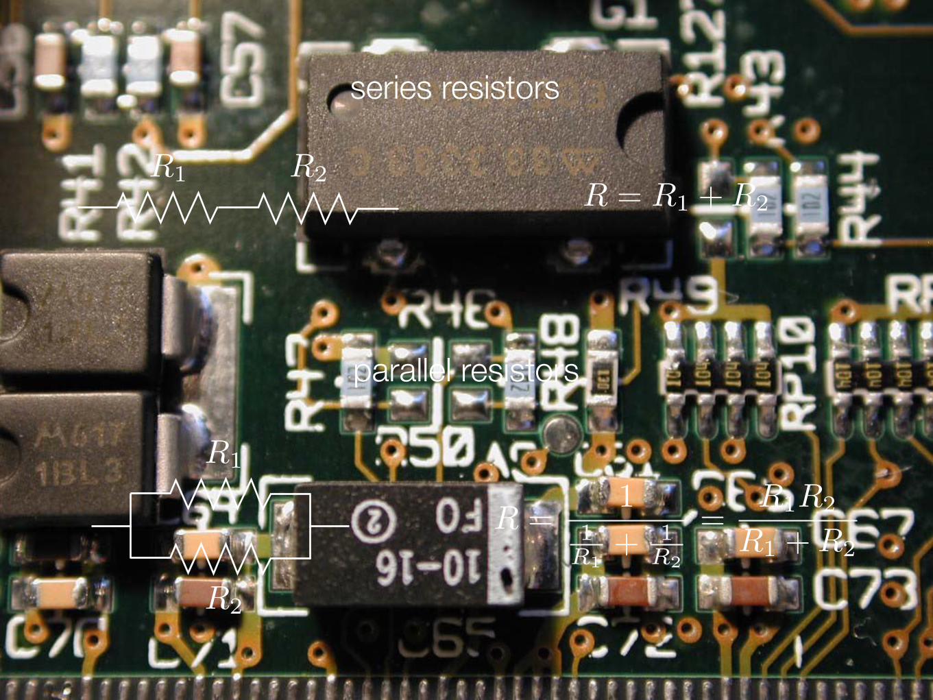
R1 R2
R = R1 + R2
R =1
1
R1+ 1
R2
=R1R2
R1 + R2
series resistors
parallel resistors
R1
R2
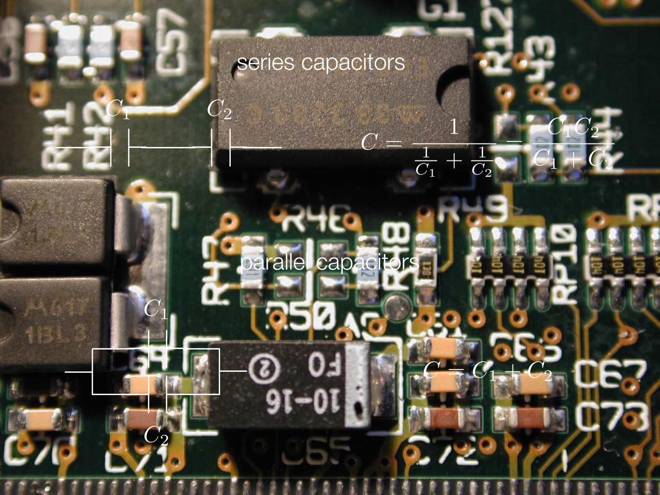
series capacitors
parallel capacitors
C =1
1
C1+ 1
C2
=C1C2
C1 + C2
C = C1 + C2
C1
C2
C1
C2

series inductors
parallel inductors
L = L1 + L2
L =1
1
L1+ 1
L2
=L1L2
L1 + L2
L1 L2
L2
L1

Voltage DividerPassive linear circuit that produces an output voltage that is a fraction of the input voltage.
R1
R2
Vin
Vout
Vout =R2
R1 + R2
Vin
assuming the output draws NO CURRENT

im•ped•ance |imˈpēdns|nounthe effective resistance of an electric circuit or component to alternating current, usually expressed as complex quantity Z = R + jX, where R is the resistance, and X is the reactance.
resistor V = IR ZR = R
ZL = jωL
ZC =1
jωC
inductor
capacitor V (t) =1
C
∫t
0
I(τ)dτ
V (t) = LdI
dt
time-domain impedance

Voltage DividerPassive linear circuit that produces an output voltage that is a fraction of the input voltage.
Vout =Z2
Z1 + Z2
VinZ1
Z2
Vin
Vout
assuming the output draws NO CURRENT

Voltage DividerA passive linear circuit that produces an output voltage that is a fraction of the input voltage.
R1
R2
Vin
Vout
Vout =R2
R1 + R2
Vin
assuming the output draws NO CURRENT

Low-Pass FilterA circuit in which lower-frequency signals are passed through, while higher-frequency signals are significantly attenuated.
R
C
Vout =1
jωRC + 1Vin
∣
∣
∣
∣
VoutVin
∣
∣
∣
∣
=1
√
1 + (ωRC)2
Vin
Vout
assuming the output draws NO CURRENT
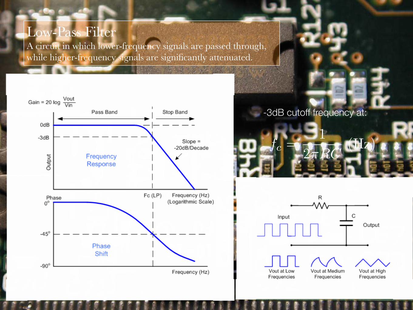
Low-Pass FilterA circuit in which lower-frequency signals are passed through, while higher-frequency signals are significantly attenuated.
fc =1
2πRC(Hz)
-3dB cutoff frequency at:

High-Pass Filtera circuit in which higher-frequency signals are passed through, while lower-frequency signals are significantly attenuated.
Vout
R
C
assuming the output draws NO CURRENT
Vin
Vout =jωRC
jωRC + 1Vin
∣
∣
∣
∣
VoutVin
∣
∣
∣
∣
=ωRC
√
1 + (ωRC)2

High-Pass Filtera circuit in which higher-frequency signals are passed through, while lower-frequency signals are significantly attenuated.
fc =1
2πRC(Hz)
-3dB cutoff frequency at: