analysis of run-in-stage wear behavior and contact ... · pdf fileanalyzed by abaqus (version...
TRANSCRIPT
Analysis of Run-in-Stage Wear Behavior and Contact Mechanicsof Metal-on-Metal Hip Joint Bearings with Different Radial Clearances
Yan Chen1, Yunping Li2,3,+, Shingo Kurosu3, Qingen Meng4,Ning Tang3, Yuichiro Koizumi3 and Akihiko Chiba3
1Department of Material Science and Engineering, Tohoku University, Sendai 980-8579, Japan2Materials Science and Engineering, Central South University, Changsha, 410083, China3Institute for Material Research, Tohoku University, Sendai 980-8577, Japan4Institute of Medical and Biological Engineering, School of Mechanical Engineering, University of Leeds, UK
We systematically elucidate the effects of radial clearance on the wear behavior of hip joint prostheses bearings during run-in-stage. Theresults indicated that bearings with smaller radial clearances exhibited lower wear rate and less abrasive wear characterized by mild surfaceroughness and sphericity. The contact mechanics and lubrication regime of MOM bearings with different radial clearances were also analyzed,indicating that bearings with radial clearance of ³20µm was more beneficial for small contact pressures even the enlarged clearance made thebearings operate under a full-fluid-to-mixed lubrication during wear. The agreement between the experimental results of wear rate (mm3/Mc)and contact mechanics and lubrication analysis indicated that the radial clearance significantly affected the wear behavior of the MOM bearings.[doi:10.2320/matertrans.M2014440]
(Received December 5, 2014; Accepted March 13, 2015; Published May 8, 2015)
Keywords: joint prostheses, CoCrMo alloy, radial clearance, contact mechanics
1. Introduction
Compared to the ultrahigh molecular weight polyethylene(UMWPE) hip joints, metal-on-metal (MOM) bearings forhip prosthesis have attracted more attention over the lasttwo decades.1) CoCr-MOM bearings exhibit extremely highsurvival rates over 510 years of service2,3) owing to theirexcellent mechanical properties and extremely low wearrate,47) and they are expected to serve for longer life than thepresent ones for younger, active patients. Despite of theseencouraging results, recent reports also indicated thatunexpected high failure rates for large head MOM bearingsand debris detachment from the rubbing surfaces, which ledto an alert from the Medicines and Healthcare productsRegulatory Agency prompting an urgent review of all MOMarticulations.8) The debris enter the blood, serum, and urine ofrecipients, cause a high incidence of adverse reaction to metaldebris (ARMD)3,911) known as periprosthetic soft tissuereactions and systemic genotoxicity.1214) Some other com-plications with MOM bearings include loosening, jointdislocation and squeaky.15,16) The contradiction betweenhigh-wear-resistant behavior and known risks of CoCrMoalloys appeal for further research to obtain MOM bearingswith improved biocompatibility.
To achieve this aim, a variety of wear tests were conductedand their results have indicated that MOM bearings wearbehavior could be affected by: (1) the materials (the use of ‘ascast’ or forged alloy with various heat treatments), (2) macro-and micro-geometry (difference in diameter and the clearancebetween mated components), (3) the resultant type andamount of lubrication, and, (4) the adoption of various hipjoint simulators with various load and motion character-istics.15,1725) Regarding the geometry feature, researcheshave concentrated on the effects of head diameter and radialclearance between the head and cup.15,21,25) Observations by
Rieker et al. indicated that longer run-in periods and greaterrun-in wear were associated with larger bearing clearances.21)
Brockett et al. also reported that increasing the clearanceof large head bearings resulted in increased friction andincidence of squeaking.15) The combined effects of the headdiameter and clearance on the wear behavior of MOMbearings were investigated by Dowson et al.25) by a hip jointsimulator, indicating that the run-in wear was more depend-ent on the diameter than the clearance. However, no optimumclearance design factors have been identified so far, andfurther systematic study is necessary on the MOM bearingswear behavior affected by clearance.
Many studies systematically analyzed the wear rates ofMOM bearings during the whole wear (including run-in andsteady state), but most of the wear took place during run-in.26,27) As for the Co-Cr-MOM systems, it was observedthat total volume wear during run-in stage is almost severaltimes higher than the steady state one.28) In the presentresearch, the clearance effect on MOM bearings wearbehavior was focused on the run-in stage. However, thiseffect could not be distinctly expressed since MOM bearingsexperience only slight wear, since the CoCrMo alloys havesuperior tribological and mechanical properties. Therefore,Hanks-balanced salt solution (HBSS) with inert nature toCoCrMo alloys was chosen as lubricant rather than dilutebovine serum, to avoid any complex organic factorinterference and artificial wear rate concerned by proteinprecipitation and degradation, or change of the boundarylubrication due to the temperature rise from friction.2934)
One reminder is that all the results obtained in this HBSSlubricated experiment can be magnified for wear resistanceestimation among bearings with various radial clearances,but without any clinical relevance because correspondingwear mechanism of the bearings alters in HBSS lubricatedenvironment.
The MOM bearings are developed from material tofinished products at one go without interruption, for an in-+Corresponding author, E-mail: [email protected]
Materials Transactions, Vol. 56, No. 6 (2015) pp. 826 to 834©2015 The Japan Institute of Metals and Materials
depth control for material microstructure of high-strengthforged CoCrMo alloys and wear behavior research on MOMbearings made of these alloys from geometrical designaspect. The high precision of computer numerical controlmachine enables the production of MOM bearings withdesired clearances ranging from several micrometers to about100 micrometers. Detailed surface morphology and shapeevolution were observed, on whose basis, the intrinsicrelationships among the volume wear rate, contact mechan-ics, and lubrication evolution of MOM bearings with variousradial clearances was analyzed, by both finite elementmethod (FEM) and classical theory.
2. Models
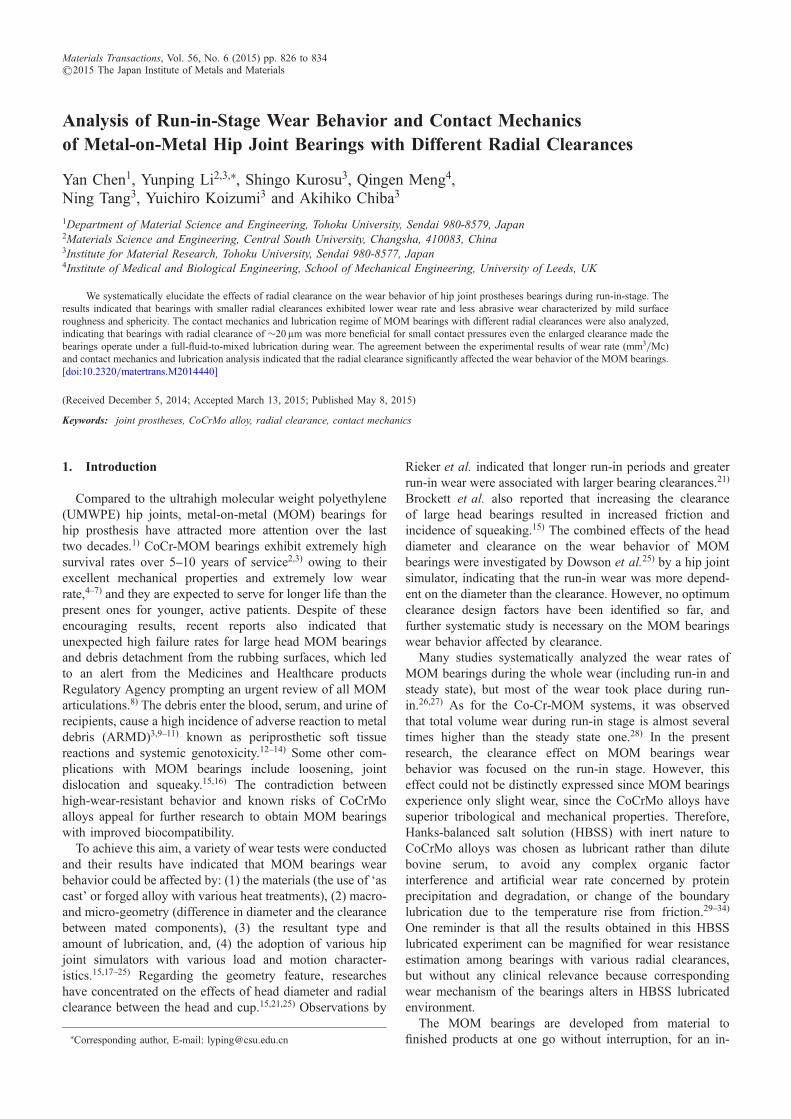
The steady state dry contact between bearing surfaces wasanalyzed by ABAQUS (version 6.11-3, Dassault SystèmesSimulia Corp.). Figure 1(a) shows a CoCrMo alloy ball-in-socket model composed of a half cup and a half head with a1.5 kN load (w/2, 2 time of a human weight) applied to thebottom surface of the head. The º 40mm heads paired with aseries of º 40.0140.3mm cups were aligned by “adjust onlyto remove overclosure”. Elastic modulus (E) of 230GPa,Poisson’s ratio (¹) of 0.3, and isotropic and linear elasticproperties were applied to the material. The geometry-basedhead and cup surfaces were defined as a contact pair; theformer was considered the slave surface and the latter themaster surface. “Surface to surface” and “small sliding”discretization was employed, and C3D8R (eight-node linearbrick, reduced integration, hourglass control) elements wereused to calculate the contact pressure between surfaces ofthe bearings. The mesh density was determined by meshconvergence, which indicated an appropriate head meshdensity of ³3 © 104, and a difference of only 0.07% in themaximum contact pressure when the mesh density increasedto ³5 © 104.
To compare the FEM results, the dry contact pressureof the bearings was also evaluated by the Hertz contacttheory using an equivalent ball-on-plane semi-infinitemodel. The radius R of the equivalent ball is determinedby:35)
R ¼ RcRh
c; ð1Þ
where Rc, Rh, and c are the radii of the cup and head, and theradial clearance, respectively. The contact radius r andmaximum contact pressure Pmax are given by:
r ¼ 3wR
E0
� �1=3
ð2Þ
and
Pmax ¼3w
2³R2; ð3Þ
respectively, where w is the load applied to the bearings, andthe equivalent elastic modulus of the material EA can besimplified as:
1
E0 ¼1� ¯2
E: ð4Þ
3. Material and Methods
3.1 Material characterizationThe material was forged Co-27.66Cr-5.5Mo-0.13N alloy
(CCMN, mass%).36) The alloy ingot was prepared by avacuum induction melting process and subsequent homog-enization at 1523K for 18 h. This was followed by hotforging at 1273K until a reduction rate of ³45%, and thenwater quenching.
Figure 1(b) shows the initial microstructure that forbearing manufacturing, by using optical microscopy(Olympus BH2-UMA). The result shows equiaxed finegrains with a mean grain size of ³20 µm. A lot of annealingtwins was also observed in the grains.
3.2 Wear tests3.2.1 Shape and surface characterization
“Large diameter” femoral heads º 40mm and acetabularcups were manufactured, for a reduced risk of dislocation andincreased motion range.20,37) Each of the components wasfinished by precision polishing in strict control to guaranteesame initial geometrical factors. Shape and surface top-ography estimation was evaluated by radius, sphericity andcenter-line-average surface roughness (Ra).
The radii and sphericities were measured by a coordinate-measuring machine (RVA600, Tokyo Seimitsu) on thesuperior hemisphere, where dominant contact occurs, at 17different locations. The radial clearance was calculated bysimply subtracting the head radius from the cup radius. Fourbearings with different initial radial clearances were used inthe tests.
The roughnesses of the samples was measured by atraditional dimensional contacting profilometer (SurfcorderDSF500, Kosaka), equipped with a diamond stylus tip ofradius 5 µm, and a digital filter assigned according to JIS01/ISO97. Roughness measurements were performed before andafter wear test at a trace speed of 0.2mm/s, with a verticalresolution of 7.5 nm. The cut-off used was 0.8mm with alength for each measurement of 7.5mm. The cups and headswere measured at hemisphere in the orthogonal 2 directionsat 4 locations over each sample surface38) and 12 measure-ments were taken, from the geometric centre to the edge, 90°apart with each other. The composite roughness Ra of thebearings was calculated by:39)
Ra ¼ffiffiffiffiffiffiffiffiffiffiffiffiffiffiffiffiffiffiffiffiffiffiRa2c þ Ra2h
p; ð5Þ
Fy
Cup
Head
Clearance
(a) (b)
Fig. 1 A ball-in-socket configuration of MOM bearings for contactsimulation, indicating a mesh refinement where surfaces contact witheach other; (b) Optical image of the initial microstructure of CCMN alloyand cup surface prior to wear tests.
Analysis of Run-in-Stage Wear Behavior and Contact Mechanics of Metal-on-Metal Hip Joint Bearings with Different Radial Clearances 827
where Rac and Rah are the roughness of the cup and head,respectively.
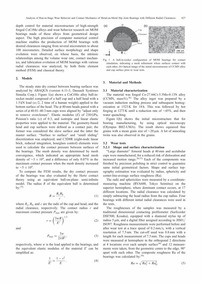
The detailed measurement locations for local sphericityand roughness measuring on the contact hemisphere, areshown in Fig. 2.3.2.2 Wear test design
Prior to the wear tests, all the samples were ultrasonicallycleaned (Sonocleaner 200D, Kaijo) using detergent, distilledwater, and ethanol subsequentl, and then kept in a vacuumdrying oven (DP33, Yamato) for at least 24 h.
To replicate the physiological walking conditions, the weartest was conducted in a universal hip joint simulator(8870 series testing system, Instron Corp., Tokyo, Japan)at 37 « 2°C under a HBSS-lubricated environment (NaCl8.0, KCl 0.4, CaCl2 0.14, NaHCO3 0.35, Na2HPO4·2H2O0.06, KH2PO4 0.06, MgSO4·2H2O 0.2 g/L). The simulatorconfiguration is shown in Fig. 3(a), in which the cup wasmounted in an anatomical position above the head40) at aninclination of 30°. A variable load ranging between 0.3 and3 kN, and triaxial rocking motions (TRM) consisting offlexion-extension (flex/ext, 43° range), abduction-adduction(ab/ad, 11° range), and in-out pelvic rotation (in/out, 12°range) at frequencies of 1Hz41) were applied on the bearings(Fig. 3(b)).
The wear tests were subjected to 1 million cycles (Mc),which is equivalent to ³ half a year of walking of a normalhuman being,42) standing for a run-in stage of wear.19,27) Theevolution of the progressive weight loss was carried out byusing a balance (AUW 300, Shimadzu), at the interrupt ofevery 0.1Mc between 0 and 0.5Mc, and every 0.25Mcbetween 0.5 and 1.0Mc during the test. Worn surfacemorphologies of the bearings were examined by scanning
electron microscopy (S-3400N Scanning Electron Micro-scope, Hitachi) and surface roughness analysis.
4. Results
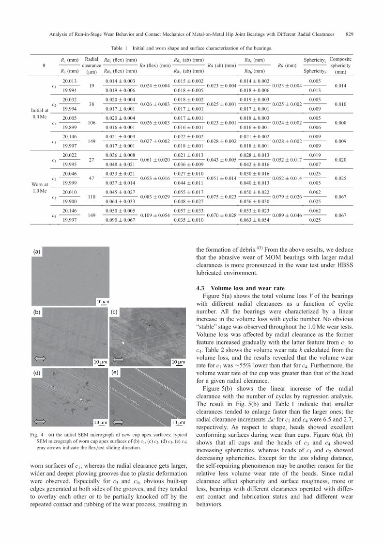
4.1 Sample characterizationTable 1 shows detailed shape and surface characterization
of the bearings before and after wear test, including radius,radial clearance, composite roughness (in flex/ext, ab/addirections and the average values), and composite sphericity.
The results show that the initial radial clearances of thebearings were 19, 38, 106, and 149 µm, and hereafter denotedby c1, c2, c3, and c4, respectively. The initial surfaceroughness satisfied the requirement for that of total hipprostheses made of metallic material according to ISO 7206-2.36,38) No significant difference was observed for the initialsurface roughness (in different directions or averaged as awhole), and sphericity of the bearings by the Student’s t-test(assuming unequal variances; two-tail, P < 0.05).
After wear test, radial clearance increased by increase ofthe cups. Oppositely, heads changed little in radius andsphericities, especially for bearings of small clearances, andheads of c1 and c2 showed excellent conforming surfacesafter wear. All the bearings have deteriorative surfaceroughness and the increased Ra, especially in flex/extdirection. The composite Ra of c1 and c2 increasedapproximately 2 fold and that of c3 and c4 3 fold,respectively, indicating that surface irregularities haveincreased significantly after 1Mc wear test.
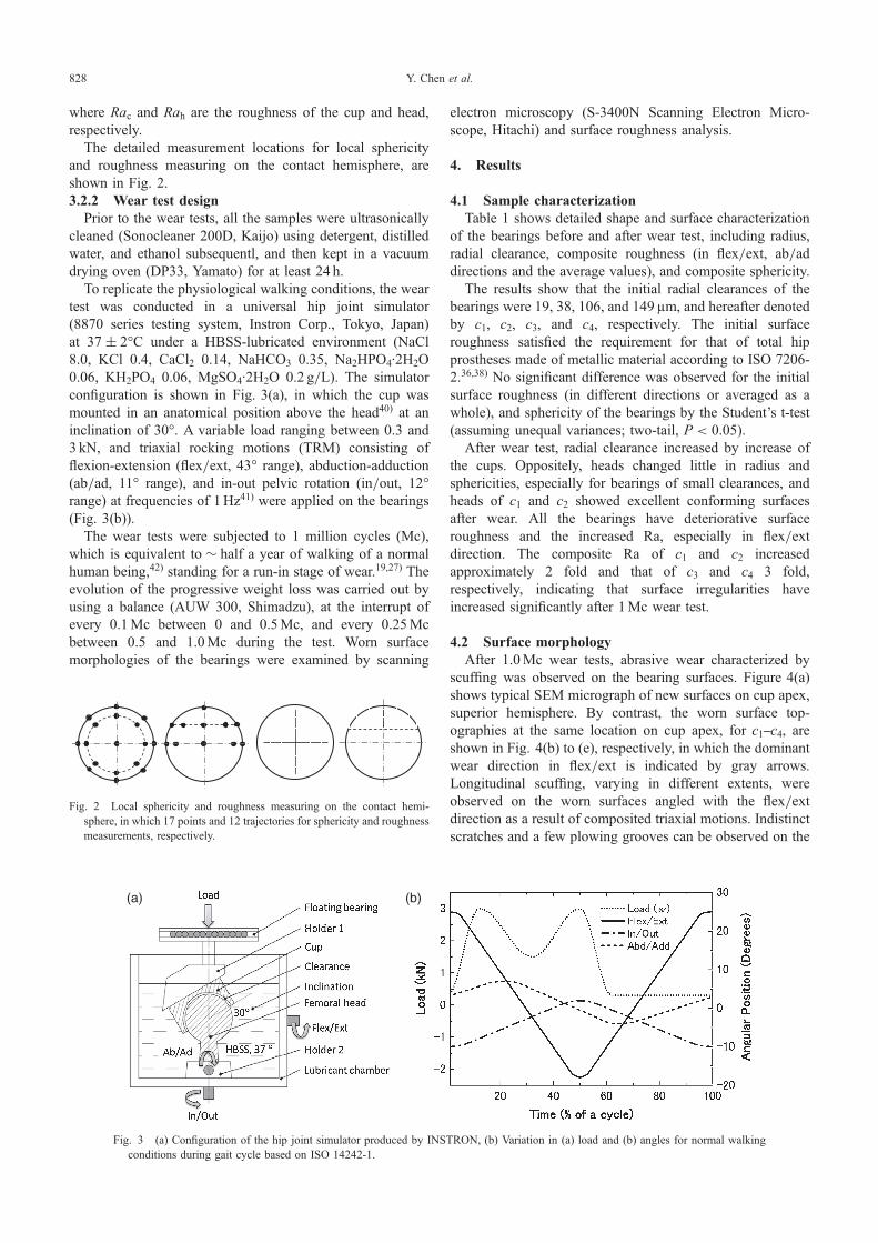
4.2 Surface morphologyAfter 1.0Mc wear tests, abrasive wear characterized by
scuffing was observed on the bearing surfaces. Figure 4(a)shows typical SEM micrograph of new surfaces on cup apex,superior hemisphere. By contrast, the worn surface top-ographies at the same location on cup apex, for c1c4, areshown in Fig. 4(b) to (e), respectively, in which the dominantwear direction in flex/ext is indicated by gray arrows.Longitudinal scuffing, varying in different extents, wereobserved on the worn surfaces angled with the flex/extdirection as a result of composited triaxial motions. Indistinctscratches and a few plowing grooves can be observed on the
Fig. 2 Local sphericity and roughness measuring on the contact hemi-sphere, in which 17 points and 12 trajectories for sphericity and roughnessmeasurements, respectively.
(a) (b)
Fig. 3 (a) Configuration of the hip joint simulator produced by INSTRON, (b) Variation in (a) load and (b) angles for normal walkingconditions during gait cycle based on ISO 14242-1.
Y. Chen et al.828
worn surfaces of c1; whereas the radial clearance gets larger,wider and deeper plowing grooves due to plastic deformationwere observed. Especially for c3 and c4, obvious built-upedges generated at both sides of the grooves, and they tendedto overlay each other or to be partially knocked off by therepeated contact and rubbing of the wear process, resulting in
the formation of debris.43) From the above results, we deducethat the abrasive wear of MOM bearings with larger radialclearances is more pronounced in the wear test under HBSSlubricated environment.
4.3 Volume loss and wear rateFigure 5(a) shows the total volume loss V of the bearings
with different radial clearances as a function of cyclicnumber. All the bearings were characterized by a linearincrease in the volume loss with cyclic number. No obvious“stable” stage was observed throughout the 1.0Mc wear tests.Volume loss was affected by radial clearance as the formerfeature increased gradually with the latter feature from c1 toc4. Table 2 shows the volume wear rate k calculated from thevolume loss, and the results revealed that the volume wearrate for c1 was ³55% lower than that for c4. Furthermore, thevolume wear rate of the cup was greater than that of the headfor a given radial clearance.
Figure 5(b) shows the linear increase of the radialclearance with the number of cycles by regression analysis.The result in Fig. 5(b) and Table 1 indicate that smallerclearances tended to enlarge faster than the larger ones; theradial clearance increments "c for c1 and c4 were 6.5 and 2.7,respectively. As respect to shape, heads showed excellentconforming surfaces during wear than cups. Figure 6(a), (b)shows that all cups and the heads of c3 and c4 showedincreasing sphericities, whereas heads of c1 and c2 showeddecreasing sphericities. Except for the less sliding distance,the self-repairing phenomenon may be another reason for therelative less volume wear rate of the heads. Since radialclearance affect sphericity and surface roughness, more orless, bearings with different clearances operated with differ-ent contact and lubrication status and had different wearbehaviors.
Table 1 Initial and worn shape and surface characterization of the bearings.
#Rc (mm) Radial
clearance(µm)
Rac (flex) (mm)Ra (flex) (mm)
Rac (ab) (mm)Ra (ab) (mm)
Rac (mm)Ra (mm)
Sphericityc Compositesphericity(mm)Rh (mm) Rah (flex) (mm) Rah (ab) (mm) Rah (mm) Sphericityh
Initial at0.0Mc
c120.013
190.014 « 0.003
0.024 « 0.0040.015 « 0.002
0.023 « 0.0040.014 « 0.002
0.023 « 0.0040.005
0.01419.994 0.019 « 0.006 0.018 « 0.005 0.018 « 0.006 0.013
c220.032
380.020 « 0.004
0.026 « 0.0030.018 « 0.002
0.025 « 0.0010.019 « 0.003
0.025 « 0.0020.005
0.01019.994 0.017 « 0.001 0.017 « 0.001 0.017 « 0.001 0.009
c320.005
1060.020 « 0.004
0.026 « 0.0030.017 « 0.001
0.023 « 0.0010.018 « 0.003
0.024 « 0.0020.005
0.00819.899 0.016 « 0.001 0.016 « 0.001 0.016 « 0.001 0.006
c420.146
1490.021 « 0.003
0.027 « 0.0020.022 « 0.002
0.028 « 0.0020.021 « 0.002
0.028 « 0.0020.009
0.00919.997 0.017 « 0.001 0.018 « 0.001 0.018 « 0.001 0.009
Worn at1.0Mc
c120.022
270.036 « 0.008
0.061 « 0.0200.021 « 0.013
0.043 « 0.0050.028 « 0.013
0.052 « 0.0170.019
0.02019.995 0.048 « 0.021 0.036 « 0.009 0.042 « 0.016 0.007
c220.046
470.033 « 0.021
0.053 « 0.0160.027 « 0.010
0.051 « 0.0140.030 « 0.016
0.052 « 0.0140.025
0.02519.999 0.037 « 0.014 0.044 « 0.011 0.040 « 0.013 0.005
c320.010
1100.045 « 0.027
0.083 « 0.0290.055 « 0.017
0.075 « 0.0230.050 « 0.022
0.079 « 0.0260.062
0.06719.900 0.064 « 0.033 0.048 « 0.027 0.056 « 0.030 0.025
c420.146
1490.050 « 0.005
0.109 « 0.0540.057 « 0.033
0.070 « 0.0280.053 « 0.023
0.089 « 0.0460.062
0.06719.997 0.090 « 0.067 0.035 « 0.010 0.063 « 0.054 0.025
(a)
(b) (c)
(d) (e)
Fig. 4 (a) the initial SEM micrograph of new cup apex surfaces; typicalSEM micrograph of worn cup apex surfaces of (b) c1, (c) c2, (d) c3, (e) c4;gray arrows indicate the flex/ext sliding direction.
Analysis of Run-in-Stage Wear Behavior and Contact Mechanics of Metal-on-Metal Hip Joint Bearings with Different Radial Clearances 829
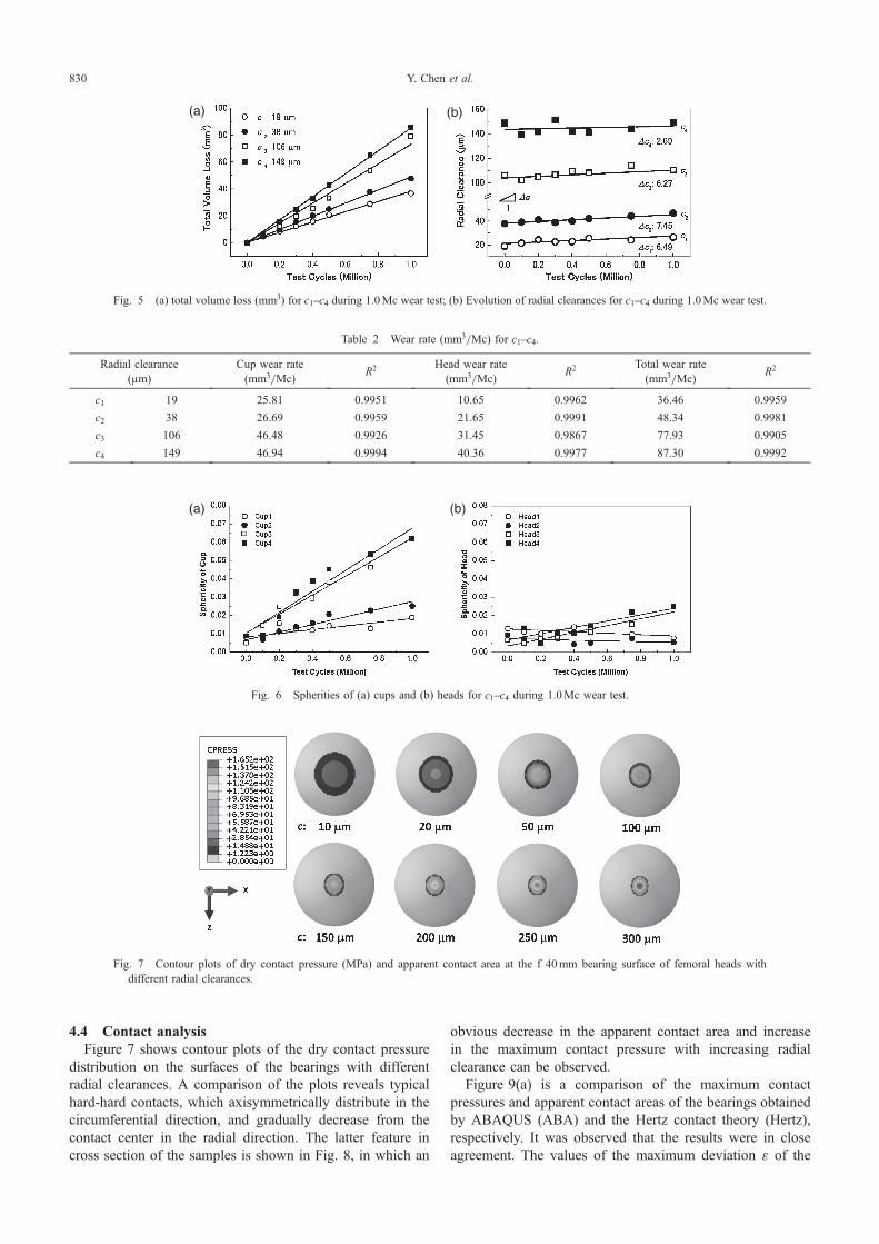
4.4 Contact analysisFigure 7 shows contour plots of the dry contact pressure
distribution on the surfaces of the bearings with differentradial clearances. A comparison of the plots reveals typicalhard-hard contacts, which axisymmetrically distribute in thecircumferential direction, and gradually decrease from thecontact center in the radial direction. The latter feature incross section of the samples is shown in Fig. 8, in which an
obvious decrease in the apparent contact area and increasein the maximum contact pressure with increasing radialclearance can be observed.
Figure 9(a) is a comparison of the maximum contactpressures and apparent contact areas of the bearings obtainedby ABAQUS (ABA) and the Hertz contact theory (Hertz),respectively. It was observed that the results were in closeagreement. The values of the maximum deviation ¾ of the
(a) (b)
Fig. 5 (a) total volume loss (mm3) for c1c4 during 1.0Mc wear test; (b) Evolution of radial clearances for c1c4 during 1.0Mc wear test.
(a) (b)
Fig. 6 Spherities of (a) cups and (b) heads for c1c4 during 1.0Mc wear test.
Fig. 7 Contour plots of dry contact pressure (MPa) and apparent contact area at the f 40mm bearing surface of femoral heads withdifferent radial clearances.
Table 2 Wear rate (mm3/Mc) for c1c4.
Radial clearance(µm)
Cup wear rate(mm3/Mc)
R2 Head wear rate(mm3/Mc)
R2 Total wear rate(mm3/Mc)
R2
c1 19 25.81 0.9951 10.65 0.9962 36.46 0.9959
c2 38 26.69 0.9959 21.65 0.9991 48.34 0.9981
c3 106 46.48 0.9926 31.45 0.9867 77.93 0.9905
c4 149 46.94 0.9994 40.36 0.9977 87.30 0.9992
Y. Chen et al.830
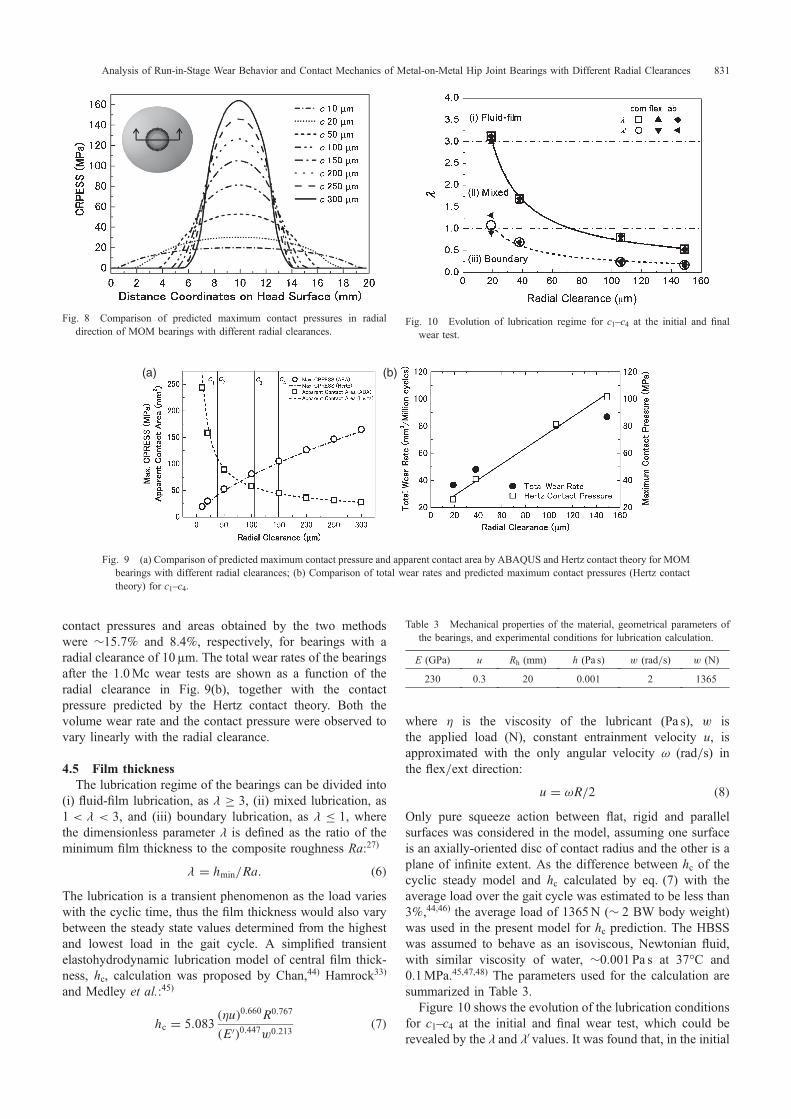
contact pressures and areas obtained by the two methodswere ³15.7% and 8.4%, respectively, for bearings with aradial clearance of 10 µm. The total wear rates of the bearingsafter the 1.0Mc wear tests are shown as a function of theradial clearance in Fig. 9(b), together with the contactpressure predicted by the Hertz contact theory. Both thevolume wear rate and the contact pressure were observed tovary linearly with the radial clearance.
4.5 Film thicknessThe lubrication regime of the bearings can be divided into
(i) fluid-film lubrication, as � 3, (ii) mixed lubrication, as1 < < 3, and (iii) boundary lubrication, as � 1, wherethe dimensionless parameter is defined as the ratio of theminimum film thickness to the composite roughness Ra:27)
¼ hmin=Ra: ð6ÞThe lubrication is a transient phenomenon as the load varieswith the cyclic time, thus the film thickness would also varybetween the steady state values determined from the highestand lowest load in the gait cycle. A simplified transientelastohydrodynamic lubrication model of central film thick-ness, hc, calculation was proposed by Chan,44) Hamrock33)
and Medley et al.:45)
hc ¼ 5:083ð©uÞ0:660R0:767
ðE0Þ0:447w0:213ð7Þ
where © is the viscosity of the lubricant (Pa s), w isthe applied load (N), constant entrainment velocity u, isapproximated with the only angular velocity ½ (rad/s) inthe flex/ext direction:
u ¼ ½R=2 ð8ÞOnly pure squeeze action between flat, rigid and parallelsurfaces was considered in the model, assuming one surfaceis an axially-oriented disc of contact radius and the other is aplane of infinite extent. As the difference between hc of thecyclic steady model and hc calculated by eq. (7) with theaverage load over the gait cycle was estimated to be less than3%,44,46) the average load of 1365N (³ 2 BW body weight)was used in the present model for hc prediction. The HBSSwas assumed to behave as an isoviscous, Newtonian fluid,with similar viscosity of water, ³0.001 Pa s at 37°C and0.1MPa.45,47,48) The parameters used for the calculation aresummarized in Table 3.
Figure 10 shows the evolution of the lubrication conditionsfor c1c4 at the initial and final wear test, which could berevealed by the and A values. It was found that, in the initial
Fig. 8 Comparison of predicted maximum contact pressures in radialdirection of MOM bearings with different radial clearances.
(a) (b)
Fig. 9 (a) Comparison of predicted maximum contact pressure and apparent contact area by ABAQUS and Hertz contact theory for MOMbearings with different radial clearances; (b) Comparison of total wear rates and predicted maximum contact pressures (Hertz contacttheory) for c1c4.
Table 3 Mechanical properties of the material, geometrical parameters ofthe bearings, and experimental conditions for lubrication calculation.
E (GPa) u Rh (mm) h (Pa s) w (rad/s) w (N)
230 0.3 20 0.001 2 1365
Fig. 10 Evolution of lubrication regime for c1c4 at the initial and finalwear test.
Analysis of Run-in-Stage Wear Behavior and Contact Mechanics of Metal-on-Metal Hip Joint Bearings with Different Radial Clearances 831
stage of the wear tests c1 operated under fluid-film lubrication,c2 under mixed lubrication, whereas c3 and c4 under boundarylubrication. During the wear tests, c1 and c2 evolved intomixed and boundary lubrication, respectively; c3 and c4 keptthe boundary lubrication. However, A for the bearingsdecreased ³3 fold as wear processed, with a similar increasein composite Ra we speculate that deteriorated surfaceroughness led to lubrication deterioration predominantly.
5. Discussion
The results showed that the radial clearance could affectcontact pressure and the lubrication, thus affect the wearbehavior of MOM bearings.
Theoretically, a head and cup with identical radii wouldmate without clearance and function with maximum contactarea and minimum contact pressure.49) Jagatia, Mak, andMeng35,50,51) similarly observed that a small clearance reducedthe contact pressures of MOM, COC, and COM bearings,respectively, similar to the results in Fig. 7 and Fig. 8. Thepredicted apparent contact area A of MOM bearingscontracted by 88.6%, and the correspondingly maximumcontact pressure increased by 87.9% when the radialclearances of MOM bearings increase from 10 to 300 µm.
In the actual test, the real contact area is also related tosurface roughness,52) assuming that the initial micro-asperitycontacts are elastic5355)
Al / n13 � w
E0
� �23
; ð9Þ
where n is the number of contacting asperities. The volumeloss V is related to both the real contact area and the slidingdistance by56)
V ¼ KAls; ð10Þwhere K is the proportionality constant.
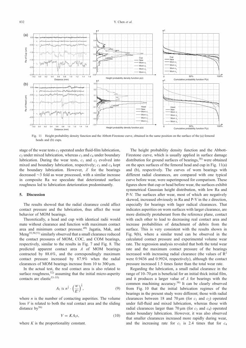
The height probability density function and the Abbott-Firestone curve, which is usually applied in surface damagedistribution for ground surfaces of bearings,38) were obtainedon the apex surfaces of the femoral head and cup in Fig. 11(a)and (b), respectively. The curves of worn bearings withdifferent radial clearances, are compared with one typicalcurve before wear, were superimposed for comparison. Thesefigures show that cup or head before wear, the surfaces exhibitsymmetrical Gaussian height distribution, with low Ra andP-V. The surfaces after wear, most of which are negativelyskewed, increased obviously in Ra and P-V in the z direction,especially for bearings with lager radical clearances. Thatindicates asperities on worn surfaces with larger clearance, aremore distinctly protuberant from the reference plane, contactwith each other to lead to decreasing real contact area andincrease probabilities of detachment of debris from thesurface. This is very consistent with the results shown inFig. 9(b), where a similar trend can be observed in thecalculated contact pressure and experimental volume wearrate. The regression analysis revealed that both the total wearrate and the maximum contact pressure of the bearingsincreased with increasing radial clearance (the values of R2
were 0.9436 and 0.9924, respectively), although the contactpressure increased 1.5 times faster than the total wear rate.
Regarding the lubrication, a small radial clearance in therange of 1070 µm is beneficial for an initial thick initial film,and it produces a larger value of for bearings with thecommon machining accuracy.38) It can be clearly observedfrom Fig. 10 that the initial lubrication regimes of thebearings in the present study were different; those with radialclearances between 18 and 70 µm (for c1 and c2) operatedunder full-fluid and mixed lubrication, whereas those withradial clearances larger than 70 µm (for c3 and c4) operatedunder boundary lubrication. However, it was also observedthat smaller clearances increased more rapidly during wear,and the increasing rate for c1 is 2.4 times that for c4
−0.2 0.0 0.2 0.4 0.6 0.8 1.0 1.2 1.4 1.6−2.5
−2.0
−1.5
−1.0
−0.5
0.0
c4
c3
c2
c1
Ra
of C
up (
um)
Distance (mm)
New
−0.6
−0.4
−0.2
0.0
0.2
0.4
0.6
z
B
Height probability density function p(z)
CupNew
Worn c1
Worn c2
Worn c3
Worn c4
100%0 50%Cumulative probability function P(z)
CupNew
Worn c1
Worn c2
Worn c3
Worn c4
z
−0.2 0.0 0.2 0.4 0.6 0.8 1.0 1.2 1.4 1.6−2.5
−2.0
−1.5
−1.0
−0.5
0.0
Ra
of H
ead
(um
)
Distance (mm)
c4
c3
c2
c1
New
−0.4
−0.3
−0.2
−0.1
0.0
0.1
0.2
0.3
B
Height probability density function p(z)
HeadNew
Worn c1
Worn c2
Worn c3
Worn c4
z
Cumulative probability function P(z)
HeadNew
Worn c1
Worn c2
Worn c3
Worn c4
50% 100%0
z
(a)
(b)
Fig. 11 Height probability density function and the Abbott-Firestone curve, obtained in the same position on the surface of the (a) femoralheads and (b) cups.
Y. Chen et al.832
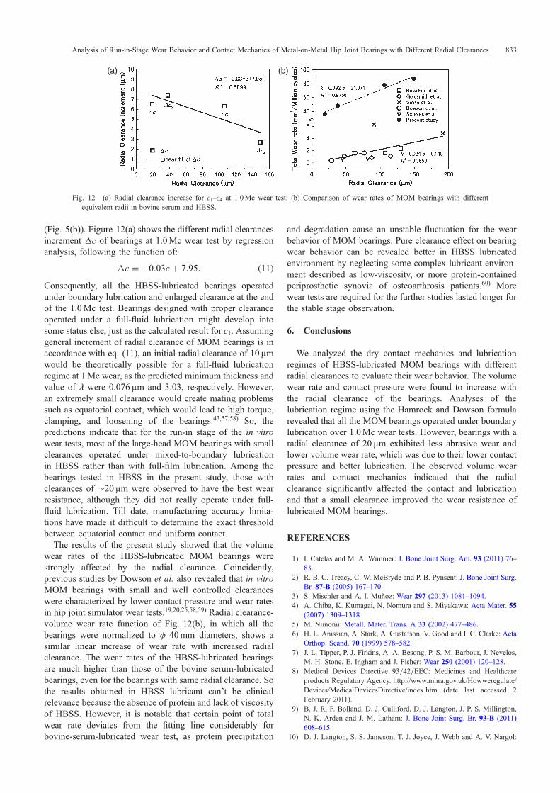
(Fig. 5(b)). Figure 12(a) shows the different radial clearancesincrement ¦c of bearings at 1.0Mc wear test by regressionanalysis, following the function of:
�c ¼ �0:03cþ 7:95: ð11ÞConsequently, all the HBSS-lubricated bearings operatedunder boundary lubrication and enlarged clearance at the endof the 1.0Mc test. Bearings designed with proper clearanceoperated under a full-fluid lubrication might develop intosome status else, just as the calculated result for c1. Assuminggeneral increment of radial clearance of MOM bearings is inaccordance with eq. (11), an initial radial clearance of 10 µmwould be theoretically possible for a full-fluid lubricationregime at 1Mc wear, as the predicted minimum thickness andvalue of were 0.076 µm and 3.03, respectively. However,an extremely small clearance would create mating problemssuch as equatorial contact, which would lead to high torque,clamping, and loosening of the bearings.43,57,58) So, thepredictions indicate that for the run-in stage of the in vitrowear tests, most of the large-head MOM bearings with smallclearances operated under mixed-to-boundary lubricationin HBSS rather than with full-film lubrication. Among thebearings tested in HBSS in the present study, those withclearances of ³20 µm were observed to have the best wearresistance, although they did not really operate under full-fluid lubrication. Till date, manufacturing accuracy limita-tions have made it difficult to determine the exact thresholdbetween equatorial contact and uniform contact.
The results of the present study showed that the volumewear rates of the HBSS-lubricated MOM bearings werestrongly affected by the radial clearance. Coincidently,previous studies by Dowson et al. also revealed that in vitroMOM bearings with small and well controlled clearanceswere characterized by lower contact pressure and wear ratesin hip joint simulator wear tests.19,20,25,58,59) Radial clearance-volume wear rate function of Fig. 12(b), in which all thebearings were normalized to º 40mm diameters, shows asimilar linear increase of wear rate with increased radialclearance. The wear rates of the HBSS-lubricated bearingsare much higher than those of the bovine serum-lubricatedbearings, even for the bearings with same radial clearance. Sothe results obtained in HBSS lubricant can’t be clinicalrelevance because the absence of protein and lack of viscosityof HBSS. However, it is notable that certain point of totalwear rate deviates from the fitting line considerably forbovine-serum-lubricated wear test, as protein precipitation
and degradation cause an unstable fluctuation for the wearbehavior of MOM bearings. Pure clearance effect on bearingwear behavior can be revealed better in HBSS lubricatedenvironment by neglecting some complex lubricant environ-ment described as low-viscosity, or more protein-containedperiprosthetic synovia of osteoarthrosis patients.60) Morewear tests are required for the further studies lasted longer forthe stable stage observation.
6. Conclusions
We analyzed the dry contact mechanics and lubricationregimes of HBSS-lubricated MOM bearings with differentradial clearances to evaluate their wear behavior. The volumewear rate and contact pressure were found to increase withthe radial clearance of the bearings. Analyses of thelubrication regime using the Hamrock and Dowson formularevealed that all the MOM bearings operated under boundarylubrication over 1.0Mc wear tests. However, bearings with aradial clearance of 20 µm exhibited less abrasive wear andlower volume wear rate, which was due to their lower contactpressure and better lubrication. The observed volume wearrates and contact mechanics indicated that the radialclearance significantly affected the contact and lubricationand that a small clearance improved the wear resistance oflubricated MOM bearings.
REFERENCES
1) I. Catelas and M. A. Wimmer: J. Bone Joint Surg. Am. 93 (2011) 7683.
2) R. B. C. Treacy, C. W. McBryde and P. B. Pynsent: J. Bone Joint Surg.Br. 87-B (2005) 167170.
3) S. Mischler and A. I. Muñoz: Wear 297 (2013) 10811094.4) A. Chiba, K. Kumagai, N. Nomura and S. Miyakawa: Acta Mater. 55
(2007) 13091318.5) M. Niinomi: Metall. Mater. Trans. A 33 (2002) 477486.6) H. L. Anissian, A. Stark, A. Gustafson, V. Good and I. C. Clarke: Acta
Orthop. Scand. 70 (1999) 578582.7) J. L. Tipper, P. J. Firkins, A. A. Besong, P. S. M. Barbour, J. Nevelos,
M. H. Stone, E. Ingham and J. Fisher: Wear 250 (2001) 120128.8) Medical Devices Directive 93/42/EEC: Medicines and Healthcare
products Regulatory Agency. http://www.mhra.gov.uk/Howweregulate/Devices/MedicalDevicesDirective/index.htm (date last accessed 2February 2011).
9) B. J. R. F. Bolland, D. J. Culliford, D. J. Langton, J. P. S. Millington,N. K. Arden and J. M. Latham: J. Bone Joint Surg. Br. 93-B (2011)608615.
10) D. J. Langton, S. S. Jameson, T. J. Joyce, J. Webb and A. V. Nargol:
(a) (b)
Fig. 12 (a) Radial clearance increase for c1c4 at 1.0Mc wear test; (b) Comparison of wear rates of MOM bearings with differentequivalent radii in bovine serum and HBSS.
Analysis of Run-in-Stage Wear Behavior and Contact Mechanics of Metal-on-Metal Hip Joint Bearings with Different Radial Clearances 833
J. Bone Joint Surg. Br. 90-B (2008) 11431151.11) D. J. Langton, S. S. Jameson, T. J. Joyce, N. J. Hallab, S. Natu and
A. V. F. Nargo: J. Bone Joint Surg. Br. 92-B (2010) 3846.12) A. J. Hart, P. D. Quinn, B. Sampson, A. Sandisson, K. D. Atkinson,
J. A. Skinner, J. J. Powell and F. W. Mosselmans: Acta Biomater. 6(2010) 44394446.
13) H. G. Willert, G. H. Buchhorn, A. Fayyazi, R. Flury, M. Windler, G.Koster and C. H. Lohmann: J. Bone Joint Surg. Am. 87 (2005) 2836.
14) E. Dunstan, D. Ladon, P. Whittingham-Jones, R. Carrington and T. W.Briggs: J. Bone Joint Surg. Am. 90 (2008) 517522.
15) C. L. Brockett, P. Harper, S. Williams, G. H. Isaac, R. S. Dwyer-Joyce,Z. M. Jin and J. Fisher: J. Mater. Sci. Mater. Med. 19 (2008) 15751579.
16) No authors listed. http://www.drugwatch.com/hip-replacement/.17) D. J. Langton, T. J. Joyce, S. S. Jameson, J. Lord, M. Van Orsouw, J. P.
Holland, A. V. F. Nargol and K. A. De Smet: J. Bone Joint Surg. Br.93-B (2011) 164171.
18) C. Heisel, J. A. Kleinhans, M. Menge and J. P. Kretzer: Int. Orthop 33(2009) 939943.
19) J. G. Bowsher, J. Nevelos, P. A. Williams and J. C. Shelton: Proc. Inst.Mech. Eng. H 220 (2006) 135143.
20) S. L. Smith, D. Dowson and A. A. J. Goldsmith: Proc. IMechE, Part H:J. Eng. Med. 215 (2001) 161170.
21) C. B. Rieker, R. Schön, R. Konrad, G. Liebentritt, P. Gnepf, M. Shen, P.Roberts and P. Grigoris: Orthop. Clin. North Am. 36 (2005) 135142.
22) F. Liu, Z. M. Jin, F. Hirt, C. Rieker, P. Robert and P. Grigoris: Proc.IMechE, Part H: J. Eng. Med. 219 (2005) 319328.
23) J. Daniel, H. Ziaee and A. Kamali: J Bone Joint Surg. Br. 92-B (2010)2027.
24) M. Silva, C. Heisel and T. P. Schmalzried: Clin. Orthop. Relat. Res. 430(2005) 5361.
25) D. Dowson, C. Hardaker, M. Flett and G. H. Isaac: J. Arthroplasty 19(2004) 124130.
26) L. S. Pinchuk, V. I. Nikolaev, E. A. Tsvetkova and V. A. Goldade:Tribology and Biophysics of Artificial Joints, Tribology and interfaceengineering series, No. 50., first edition, (ELSEVIER B.V., theNetherlands, 2006) p. 260.
27) D. Dowson: Proc. IMechE, Part H: J. Eng. Med. 220 (2006) 161171.28) M. Alvarez-Vera, J. A. Ortega-Saenz and M. A. L. Hernandez-
Rodríguez: Wear 301 (2013) 175181.29) Y. S. Liao, P. D. Benya and H. A. McKellop: J. Biomed. Mater. Res. 48
(1999) 465473.30) A. Wang, C. Stark and J. H. Dumbleton: Proc. IMechE, Part H: J. Eng.
Med. 210 (1996) 141155.31) Z. Lu and H. McKellop: Proc. IMechE, Part H: J. Eng. Med. 211
(1997) 101108.32) M. P. Gispert, A. P. Serro, R. Colaço and B. Saramago: Wear 260
(2006) 149158.33) J. B. Medley, F. W. Chan, J. J. Krygier and J. D. Bobyn: Clin. Orthop.
Relat. Res. 329 (1996) S148S159.34) A. Iwabuchi, J. W. Lee and M. Uchidate: Wear 263 (2007) 492500.35) Q. Meng, F. Liu, J. Fisher and Z. M. Jin: Tribol. Int. 63 (2013) 5160.36) ISO 7206-2:1999. Implants for surgery®partial and total hip joint
prostheses®part 2: Articulating surfaces made of metallic, ceramicand plastics materials, International Organization for Standardization,(1999).
37) R. D. Crowninshield, W. J. Maloney, D. H. Wentz, S. M. Humphreyand C. R. Blanchard: Clin Orthop 429 (2004) 102107.
38) A. L. L. Oliveira, R. G. Lima, E. G. Cueva and R. D. Queiroz: Wear271 (2011) 23402345.
39) L. Mattei, F. Di Puccio, B. Piccigallo and E. Ciulli: Ecotrib. 44 (2009)532549.
40) V. Saikko, T. Ahlroos, H. Revitzer, O. Ryti and P. Kuosmanen: Tribol.Int. 60 (2013) 7076.
41) ISO 14242-1:2002, Implants for surgery®wear of total hip-jointprostheses®part 1: loading and displacement parameters for wear-testing machines and corresponding environmental conditions for test,International Organization for Standardization, (2002).
42) M. Silva, E. F. Shepherd, W. O. Jackson, F. J. Dorey and T. P.Schmalzried: J. Arthroplasty 17 (2002) 693697.
43) P. S. Walker and B. L. Gold: Wear 17 (1971) 285299.44) F. W. Chan, J. B. Medley, J. D. Bobyn and J. J. Krygier: ASTM STP
1346 (1998) 111128.45) J. B. Medley, J. J. Krygier, J. D. Bobyn, F. W. Chan, A. Lippincott and
M. Tanzer: Proc. IMechE, Part H: J. Eng. Med. 211 (1997) 8999.46) N. Y. Cheng, J. B. Medley, J. D. Bobyn and J. J. Krygier: Boundary
and Mixed Lubrication: Science and Applications, Tribology Series 40,first edition, ed. by D. Dowson, M. Priest, G. Dalmaz and A. A.Lubrecht, (Elsevier, 2002) pp. 387397.
47) G. W. Stachowiak and A. W. Batchelor: Tribology Series, 24, EngineerTribology, (Elsevier Science Publishers B.V. 24, 1993).
48) J. Kestin, H. E. Khalifa and R. J. Correia: J. Phys. Chem. Ref. Data 10(1981) 5770.
49) M. Silva, C. Heisel, H. McKellop and T. P. Schmalzried: The Adult Hip,second edition, ed. by J. J. Callaghan, A. G. Rosenberg and H. E.Rubash (Lippincott Williams & Wilkins, Philadelphia, PA, 2007)p. 251.
50) M. Jagatia and Z. M. Jin: Proc. IMechE, Part H: J. Eng. Med. 215(2001) 531541.
51) M. M. Mak and Z. M. Jin: Proc. IMechE, Part H: J. Eng. Med. 216(2002) 231236.
52) G. W. Stachowiak and A. W. Batchelor: Tribology Series, 24, EngineerTribology, (Elsevier Science Publishers B.V. 1993) pp. 527556.
53) D. J. Whitehouse and J. F. Archard: Proc. Roy. Soc., London, Series A316 (1970) 97121.
54) R. A. Onions and J. F. Archard: J. Phys. D: Appl. Phys. 6 (1973) 289304.
55) S. Z. Wen and P. Huang: Principles of Tribology, third edition,(Tsinghua, Beijing, 2008).
56) J. F. Archard: J. Appl. Phys. 32 (1961) 14201425.57) J. A. Schey: Clin. Orthop. Relat. Res. 329 (1996) S115S127.58) S. C. Scholes, S. M. Green and A. Unsworth: Proc. IMechE, Part H:
J. Eng. Med. 215 (2001) 523530.59) A. A. Goldsmith, D. Dowson, G. H. Isaac and J. G. Lancaster: Proc.
IMechE, Part H: J. Eng. Med. 214 (2000) 3947.60) A. F. Cooke, D. Dowson and V. Wright: Eng. Med. 7 (1978) 6672.
Nomenclature
A: apparent contact area (mm2)Al: real contact area (mm2)c: radial clearance (µm)¦c: radial clearance increment (µm)E: elastic modulus (MPa)EA: equivalent elastic modulus (MPa)©: viscosity of lubricant (Pa s)hc: central film thickness (nm)K: proportionality constantk: volume wear rate (mm3/Mc)kc: volume wear rate of cup (mm3/Mc)kh: volume wear rate of head (mm3/Mc): dimensionless ration: number of contact asperitiesPmax: maximum contact pressure (MPa)r: contact radius (mm)R: equivalent radius for the ball-on-plane model (mm)Ra: composite roughness (nm)Rac: arithmetic average roughness of cup (nm)Rah: arithmetic average roughness of head (nm)Rc: radius of cup (mm)Rh: radius of femoral head (mm)s: sliding distance (mm)u: entraining velocity (mm/s)¹: Poisson’s ratioV: total volume loss (mm3)½: angular velocity in Flex/Ext direction (rad/s)w: applied load (N)
Y. Chen et al.834