analysis of statically determinate structures · classify each of the pin-connected structures...
TRANSCRIPT
1
! Idealized Structure! Principle of Superposition! Equations of Equilibrium! Determinacy and Stability
! Beams! Frames! Gable Frames
! Application of the Equations of Equilibrium! Analysis of Simple Diaphragm and Shear
Wall Systems Problems
Analysis of Statically Determinate Structures
2
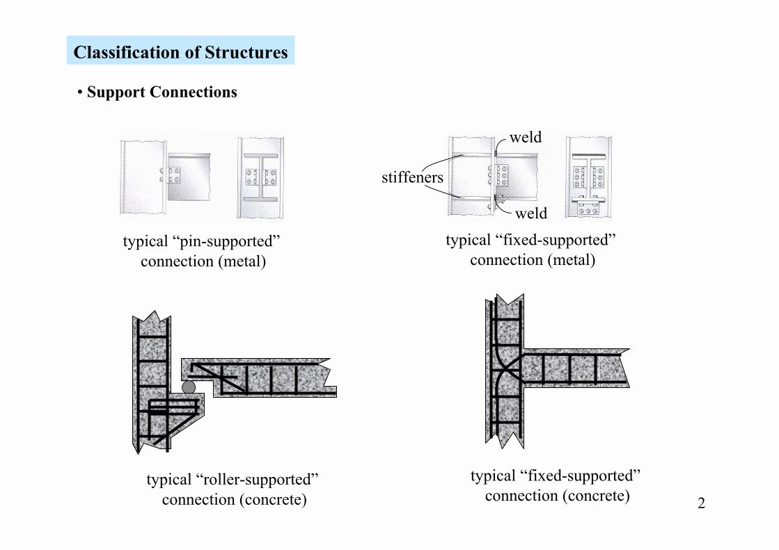
Classification of Structures
� Support Connections
typical �roller-supported� connection (concrete)
typical �fixed-supported� connection (concrete)
typical �pin-supported� connection (metal)
stiffeners
weld
weldtypical �fixed-supported�
connection (metal)
3
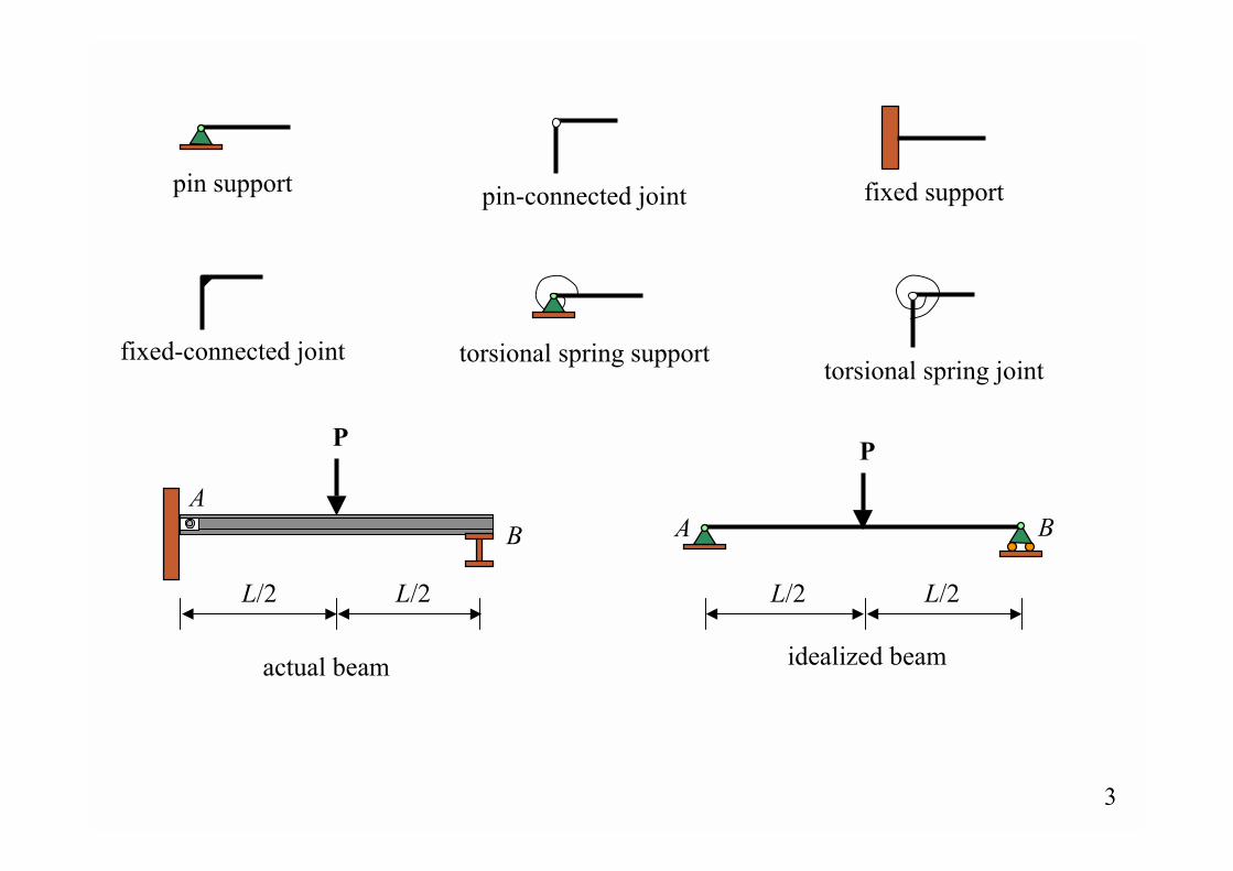
fixed-connected joint
pin-connected joint fixed support
AB
P
actual beam
L/2 L/2
torsional spring joint
pin support
torsional spring support
idealized beam
A B
L/2 L/2
P
4
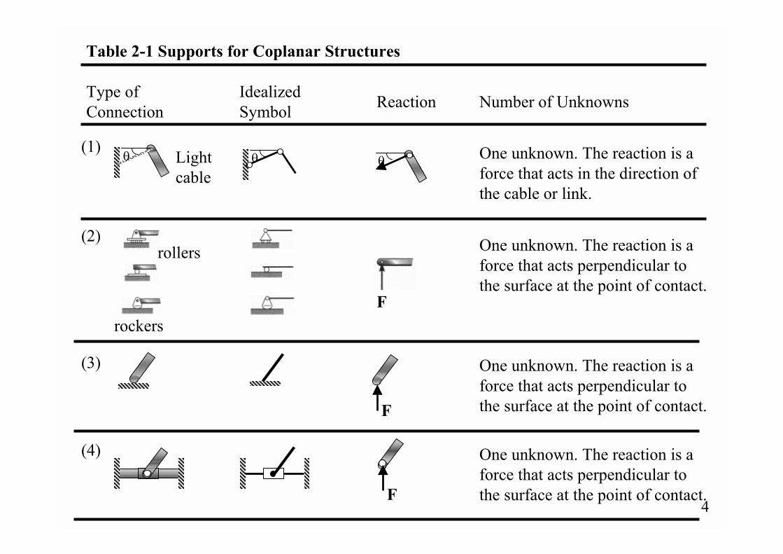
One unknown. The reaction is aforce that acts perpendicular to the surface at the point of contact.
One unknown. The reaction is aforce that acts perpendicular to the surface at the point of contact.
F
One unknown. The reaction is aforce that acts in the direction of the cable or link.
One unknown. The reaction is aforce that acts perpendicular to the surface at the point of contact.
Type of Connection
Idealized Symbol Number of UnknownsReaction
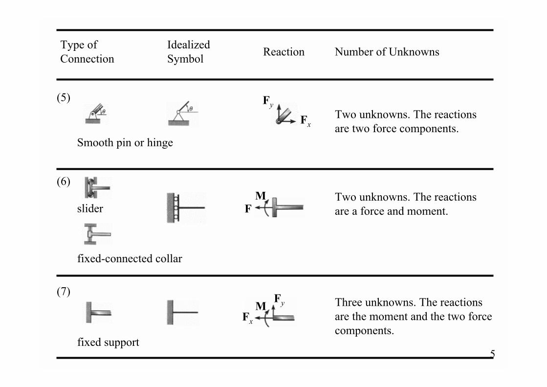
Table 2-1 Supports for Coplanar Structures
(3)
F
(4)
F
(1)θ Light
cableθ θ
rockers
(2)rollers
5
fixed-connected collar
Two unknowns. The reactions are two force components.
Fy
Fx
Type of Connection
Idealized Symbol Number of UnknownsReaction
FM Two unknowns. The reactions
are a force and moment.
Three unknowns. The reactions are the moment and the two forcecomponents.
MFy
Fx
(7)
fixed support
(5)
Smooth pin or hinge
(6)
slider
6
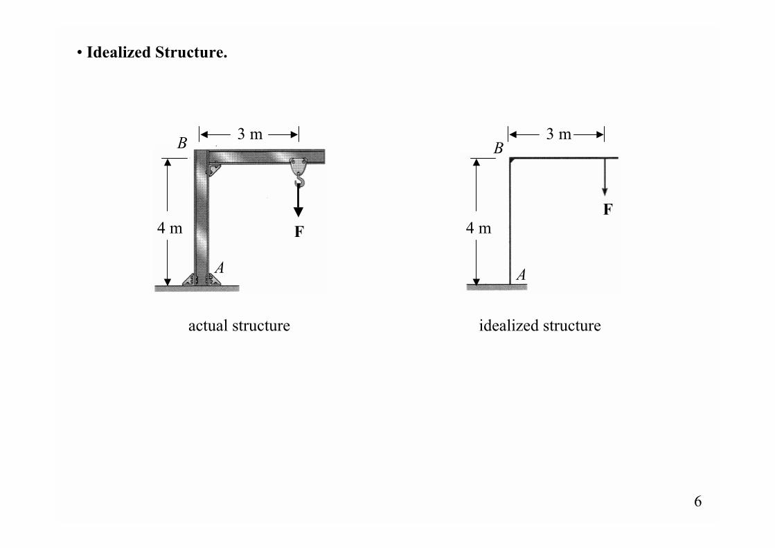
� Idealized Structure.
F
3 m
4 m
A
B
actual structure idealized structure
3 m
4 m
A
B
F
7
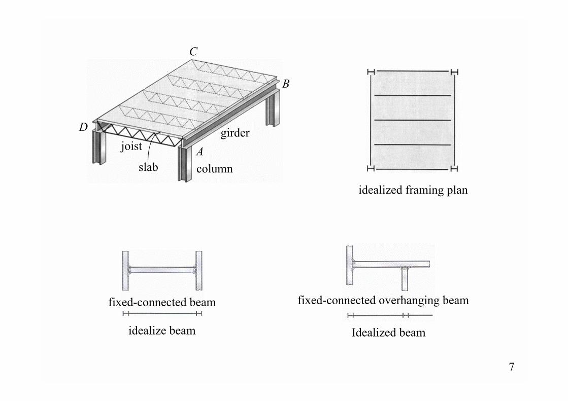
idealized framing plan
A
B
C
Djoist
slab column
girder
fixed-connected beam
idealize beam
fixed-connected overhanging beam
Idealized beam
8
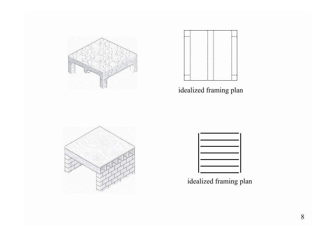
idealized framing plan
idealized framing plan
9
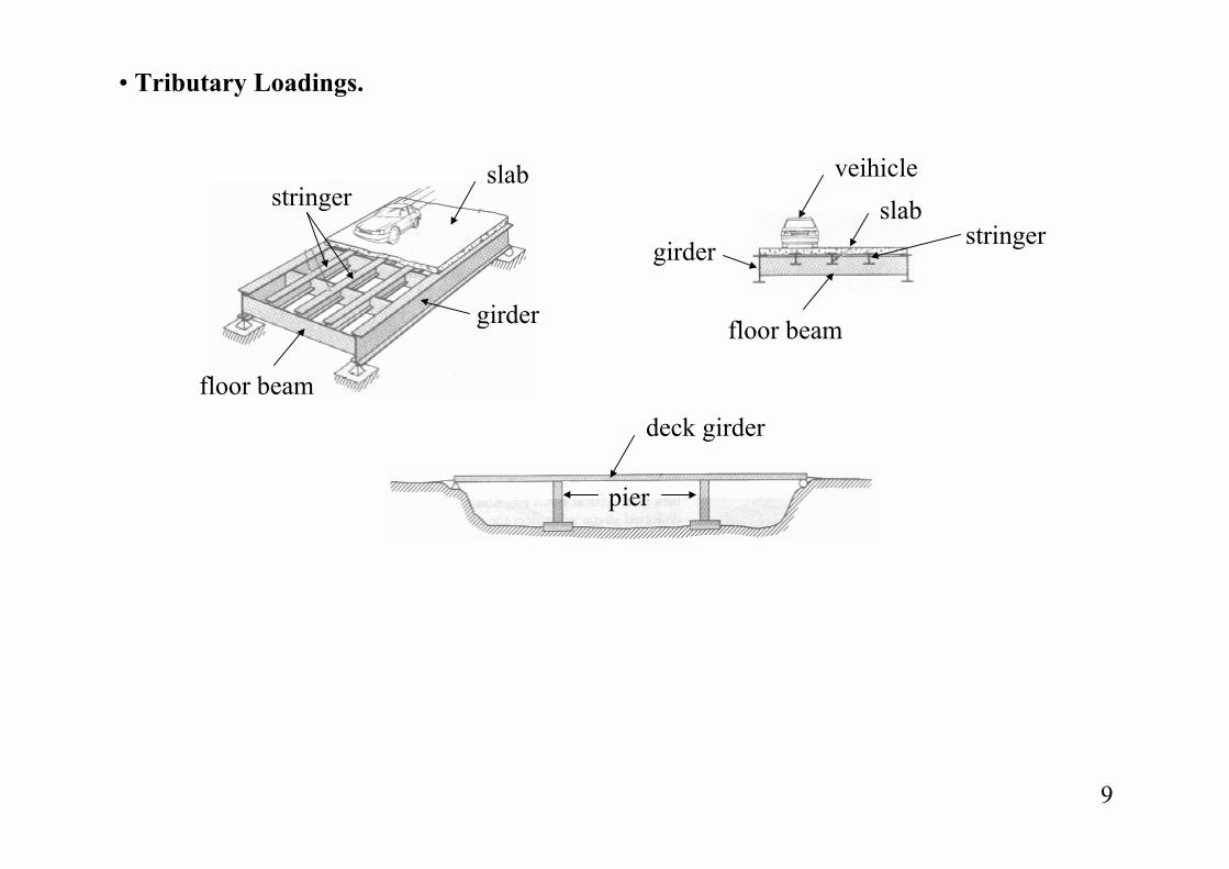
� Tributary Loadings.
stringer
floor beam
girder
slab
deck girder
pier
veihicleslab
stringer
floor beam
girder
10
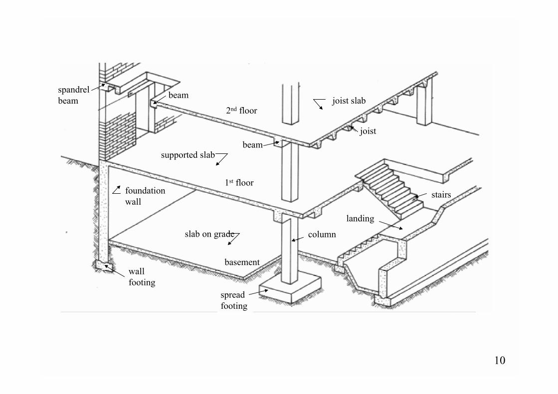
wall footing
slab on grade column
landing
stairsfoundationwall
basement
1st floor
supported slab
2nd floor
beam
beam joist slab
joist
spread footing
spandrelbeam
11
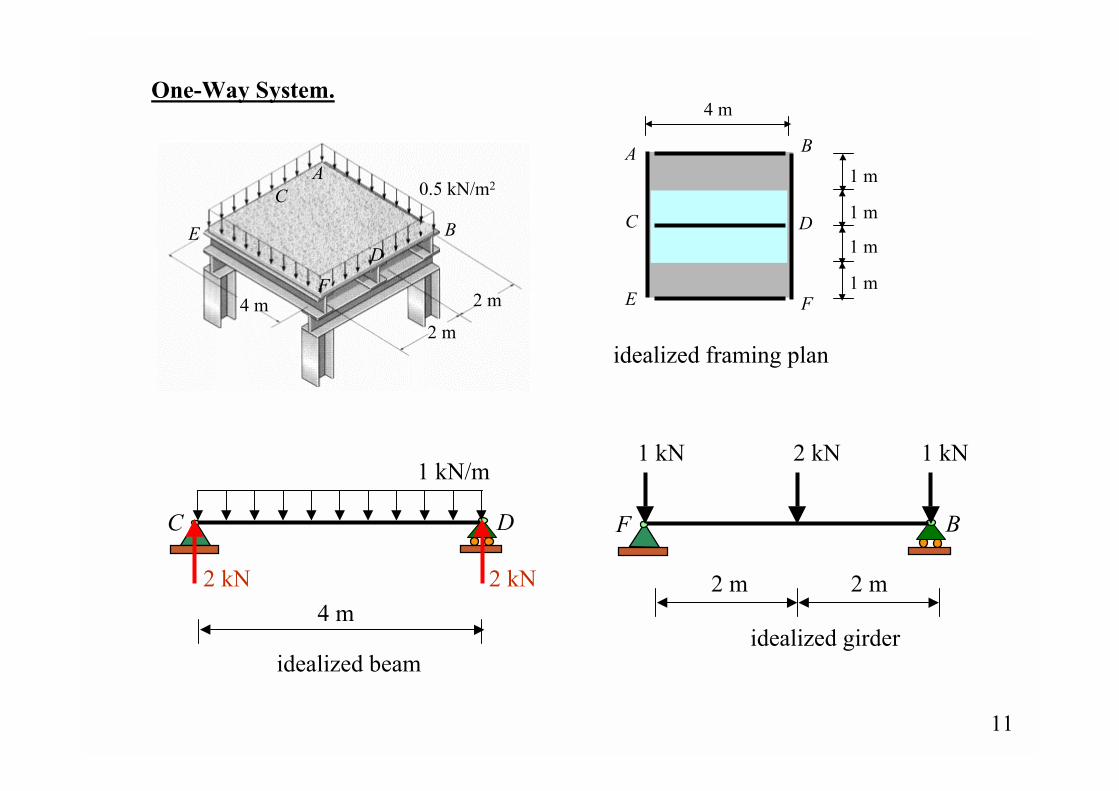
A B
C D
E F
idealized framing plan
4 m
4 m2 m
2 m
A
B
C
DE
F
0.5 kN/m2
One-Way System.
C D
4 m
idealized beam
1 m
1 m
1 m
1 m
1 kN/m
2 kN 2 kN
idealized girder
F B
2 m 2 m
2 kN1 kN 1 kN

12
A B
C D
E F
Idealized framing planfor one-way slab actionrequires 2/ 12 ≥LL
L2
L1
L1L1/2L1/2
concrete slab isreinforced in two directions, poured on plane forms
Agirder
beamcolumn
13
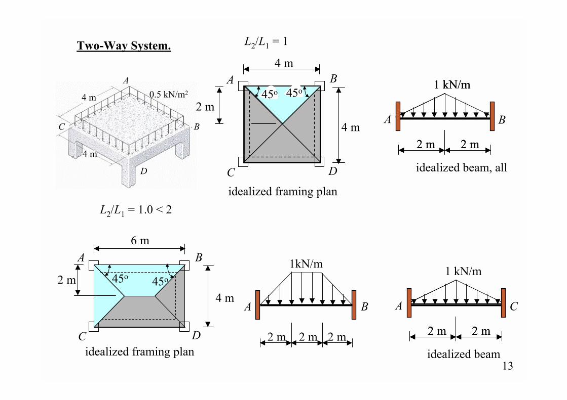
6 m
4 m
idealized framing plan
A B
C D
L2/L1 = 1.0 < 2
4 m
4 m
idealized framing plan
A B
C D
L2/L1 = 1Two-Way System.
2 m
4 m
4 m
A
BC
D
0.5 kN/m2 45o 45o
2 m
45o45o
2 m 2 m
A C
idealized beam
1 kN/m
2 m 2 m
A B
1kN/m
2 m 2 m 2 m
2 m 2 m
A B
idealized beam, all
1 kN/m
2 m 2 m
1 kN/m
14
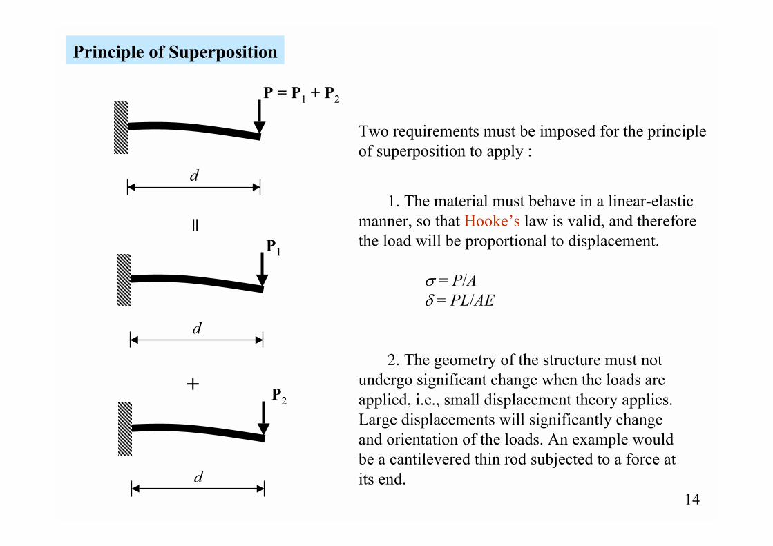
Principle of Superposition
P1
d
+
Two requirements must be imposed for the principleof superposition to apply :
1. The material must behave in a linear-elastic manner, so that Hooke�s law is valid, and therefore the load will be proportional to displacement.
σ = P/Aδ = PL/AE
2. The geometry of the structure must not undergo significant change when the loads are applied, i.e., small displacement theory applies. Large displacements will significantly changeand orientation of the loads. An example wouldbe a cantilevered thin rod subjected to a force at its end.
=
P = P1 + P2
d
P2
d
15
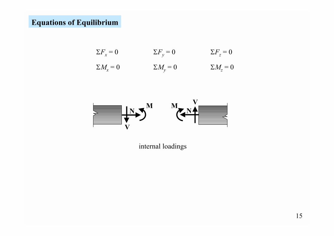
Equations of Equilibrium
ΣFx = 0 ΣFy = 0 ΣFz = 0
ΣMx = 0 ΣMy = 0 ΣMz = 0
V
internal loadings
NM M
NV
16
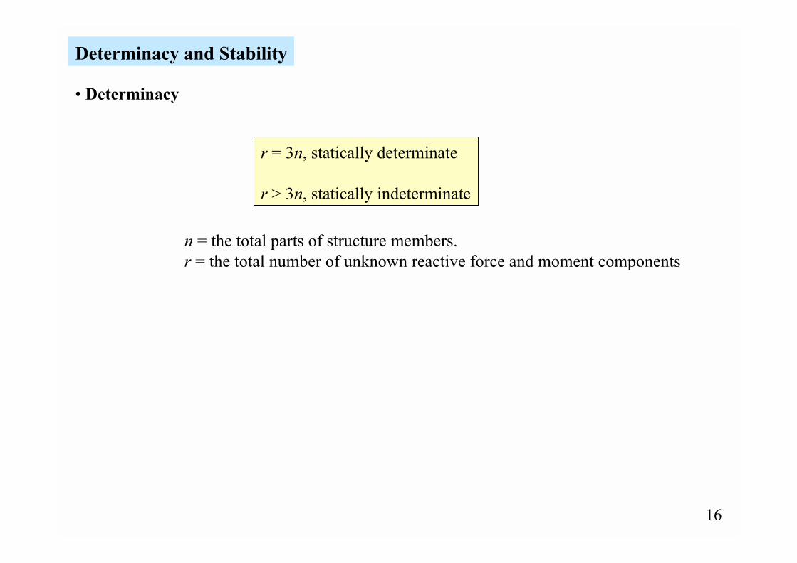
Determinacy and Stability
r = 3n, statically determinate
r > 3n, statically indeterminate
n = the total parts of structure members.r = the total number of unknown reactive force and moment components
� Determinacy
17
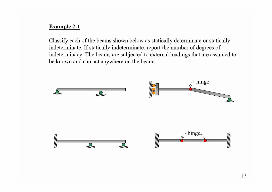
Example 2-1
Classify each of the beams shown below as statically determinate or staticallyindeterminate. If statically indeterminate, report the number of degrees ofindeterminacy. The beams are subjected to external loadings that are assumed tobe known and can act anywhere on the beams.
hinge
hinge
18
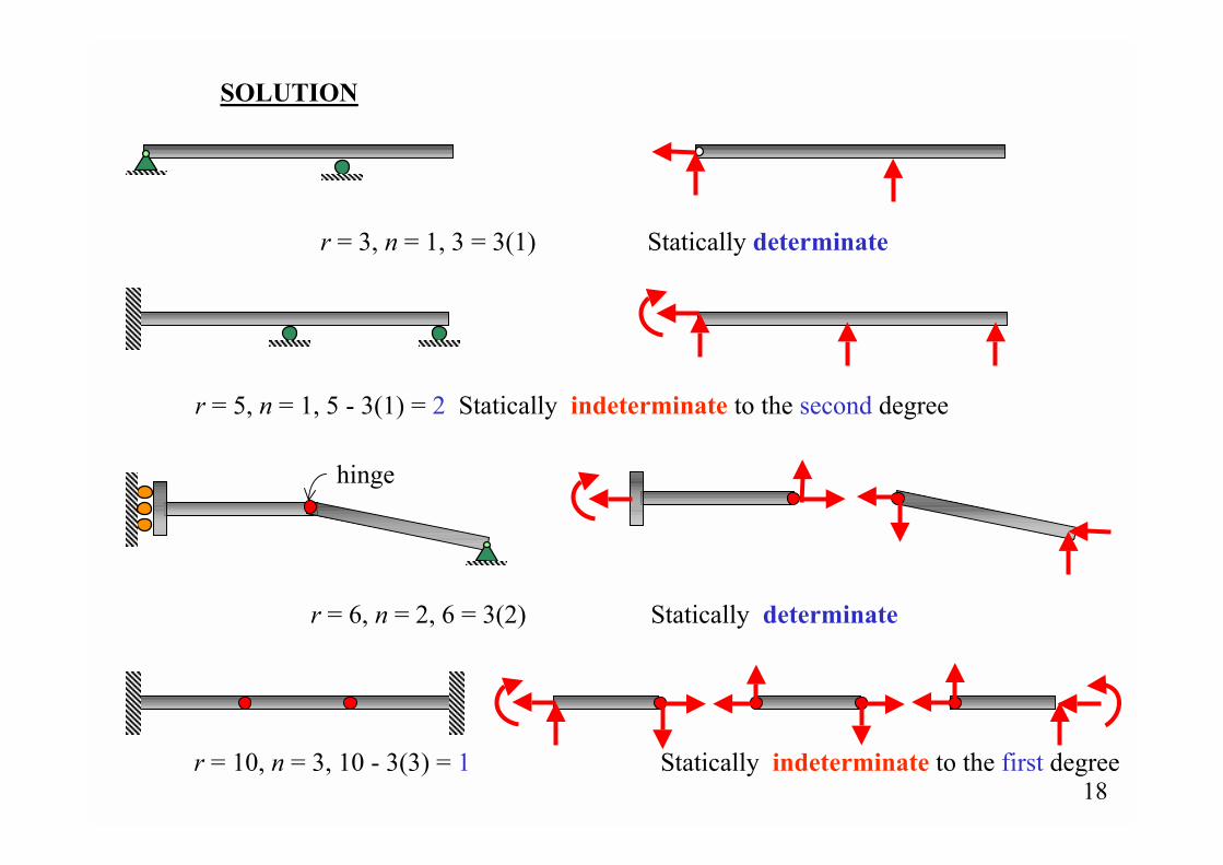
SOLUTION
r = 3, n = 1, 3 = 3(1) Statically determinate
r = 5, n = 1, 5 - 3(1) = 2 Statically indeterminate to the second degree
r = 6, n = 2, 6 = 3(2) Statically determinate
r = 10, n = 3, 10 - 3(3) = 1 Statically indeterminate to the first degree
hinge
19
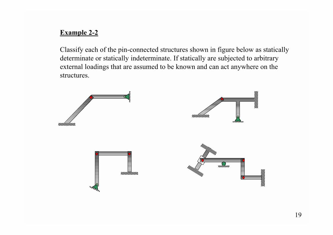
Example 2-2
Classify each of the pin-connected structures shown in figure below as staticallydeterminate or statically indeterminate. If statically are subjected to arbitraryexternal loadings that are assumed to be known and can act anywhere on thestructures.

20
SOLUTION
r = 7, n = 2, 7 - 3(2) = 1 Statically indeterminate to the first degree
r = 9, n = 3, 9 = 3(3) Statically determinate
21
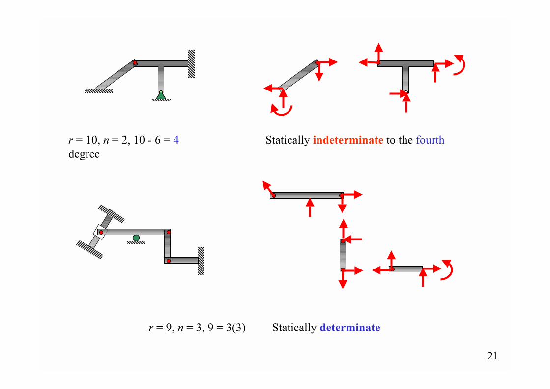
r = 10, n = 2, 10 - 6 = 4 Statically indeterminate to the fourthdegree
r = 9, n = 3, 9 = 3(3) Statically determinate
22
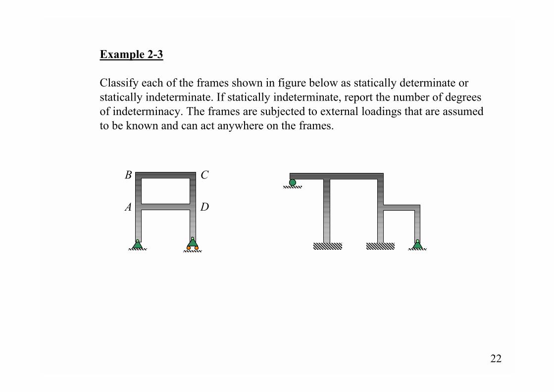
Example 2-3
Classify each of the frames shown in figure below as statically determinate orstatically indeterminate. If statically indeterminate, report the number of degreesof indeterminacy. The frames are subjected to external loadings that are assumedto be known and can act anywhere on the frames.
B
A
C
D

23
B
A
C
D
SOLUTION
r = 9, n = 2, 9 - 6 = 3 Statically indeterminate to the third degree
r = 15, n = 3, 15 - 9 = 6 Statically indeterminate to the sixth degree
24
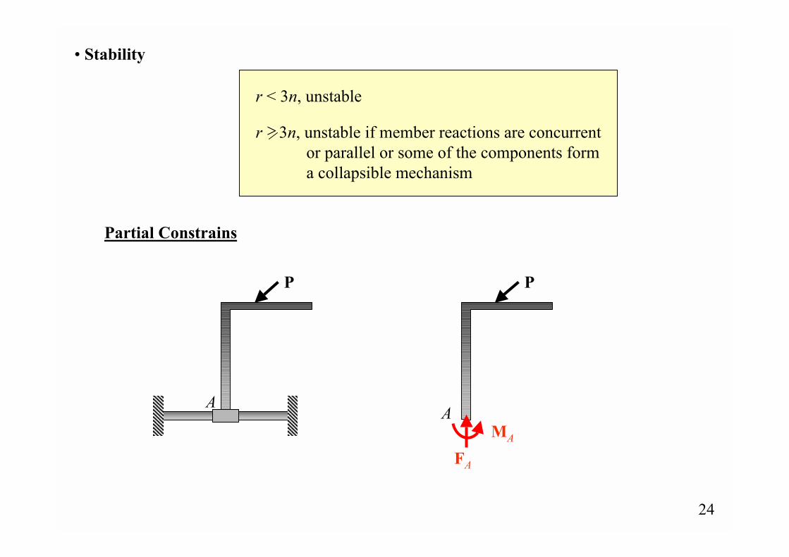
� Stability
Partial Constrains
A
P P
AMA
FA
r < 3n, unstable
>r 3n, unstable if member reactions are concurrent or parallel or some of the components form a collapsible mechanism
25
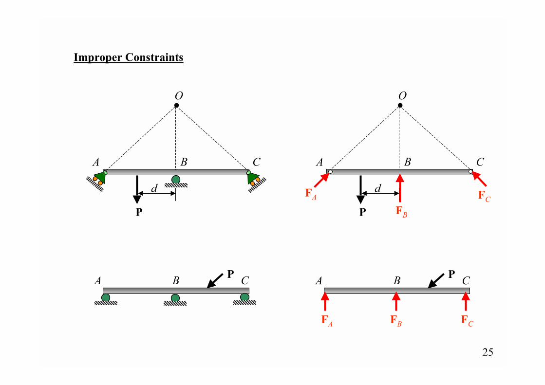
Improper Constraints
P
A B C
d
O O
P
A B C
dFA
FB
FC
A B CP A B CP
FA FB FC
26
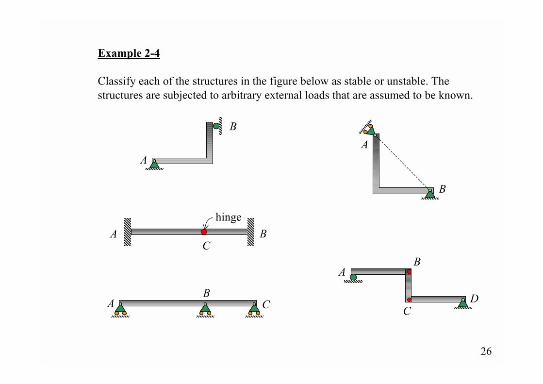
Example 2-4
Classify each of the structures in the figure below as stable or unstable. Thestructures are subjected to arbitrary external loads that are assumed to be known.
hingeA B
C
AB
C
A
B
AB
CD
A
B
27
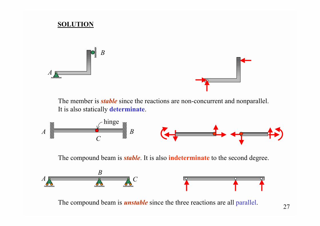
SOLUTION
hingeA B
C
The member is stable since the reactions are non-concurrent and nonparallel.It is also statically determinate.
The compound beam is stable. It is also indeterminate to the second degree.
The compound beam is unstable since the three reactions are all parallel.
A
B
AB
C
28
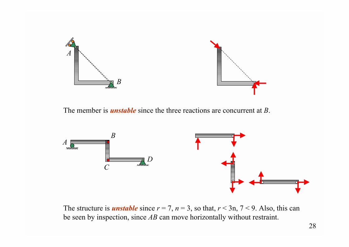
The member is unstable since the three reactions are concurrent at B.
The structure is unstable since r = 7, n = 3, so that, r < 3n, 7 < 9. Also, this canbe seen by inspection, since AB can move horizontally without restraint.
AB
CD
A
B
29
Ay
Ax
P1
P2 Cx
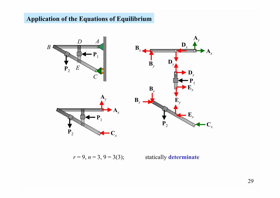
Application of the Equations of Equilibrium
AB
C
D
E
P1
P2
Dx
Dy
Dx
Bx
By
Bx
By
Ey
Ex
Ex
P2
P1
Ay
Ax
Cx
r = 9, n = 3, 9 = 3(3); statically determinate
30
AB
CP2
P1
B
P2
P1 Ay
Ax
Cy
Cx
P1
P2
Ay
Ax
Cy
Cx
Bx
Bx
By
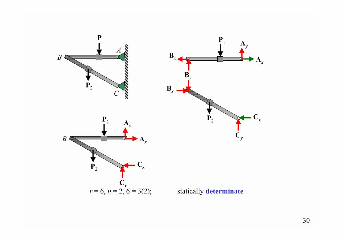
r = 6, n = 2, 6 = 3(2); statically determinate
31
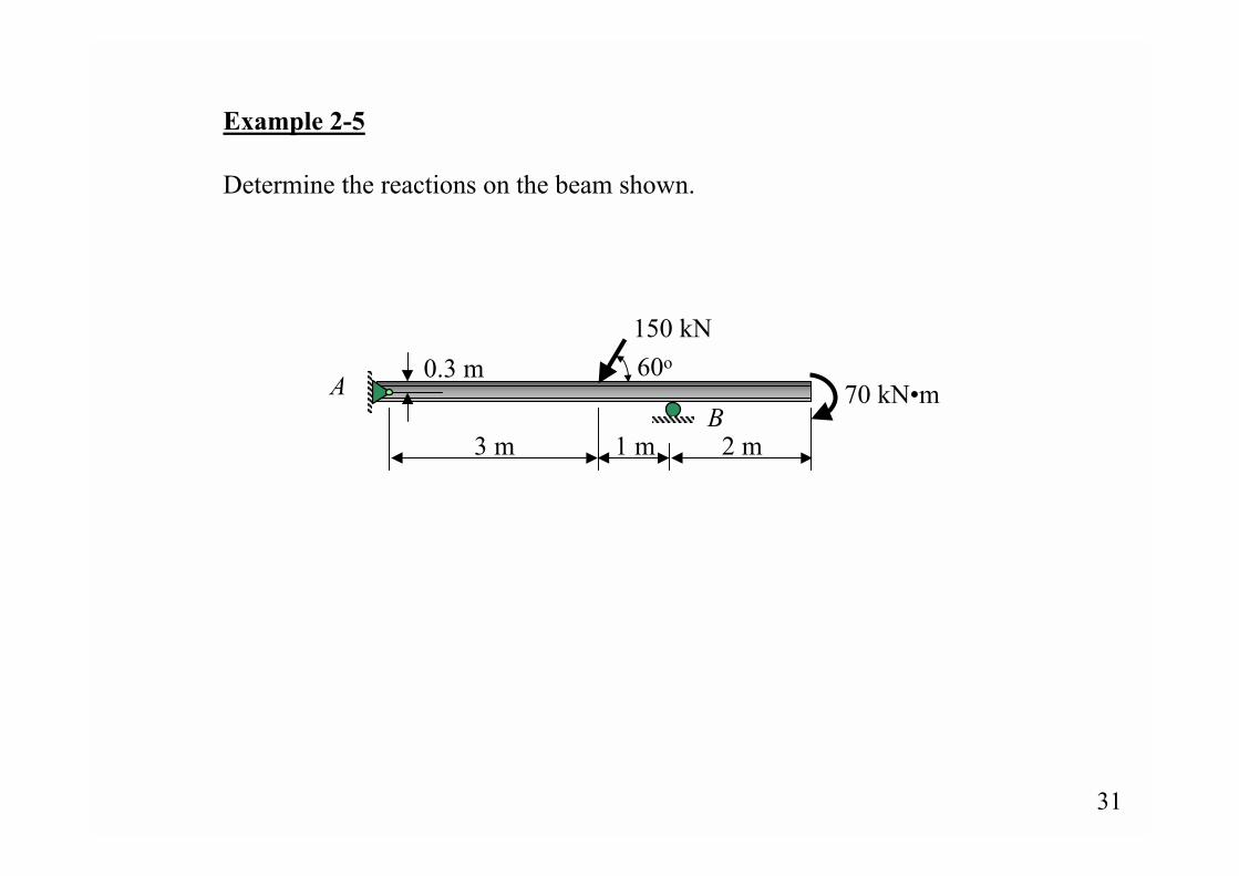
Example 2-5
Determine the reactions on the beam shown.
3 m 1 m 2 m
70 kN�m
150 kN60o0.3 mA
B
32
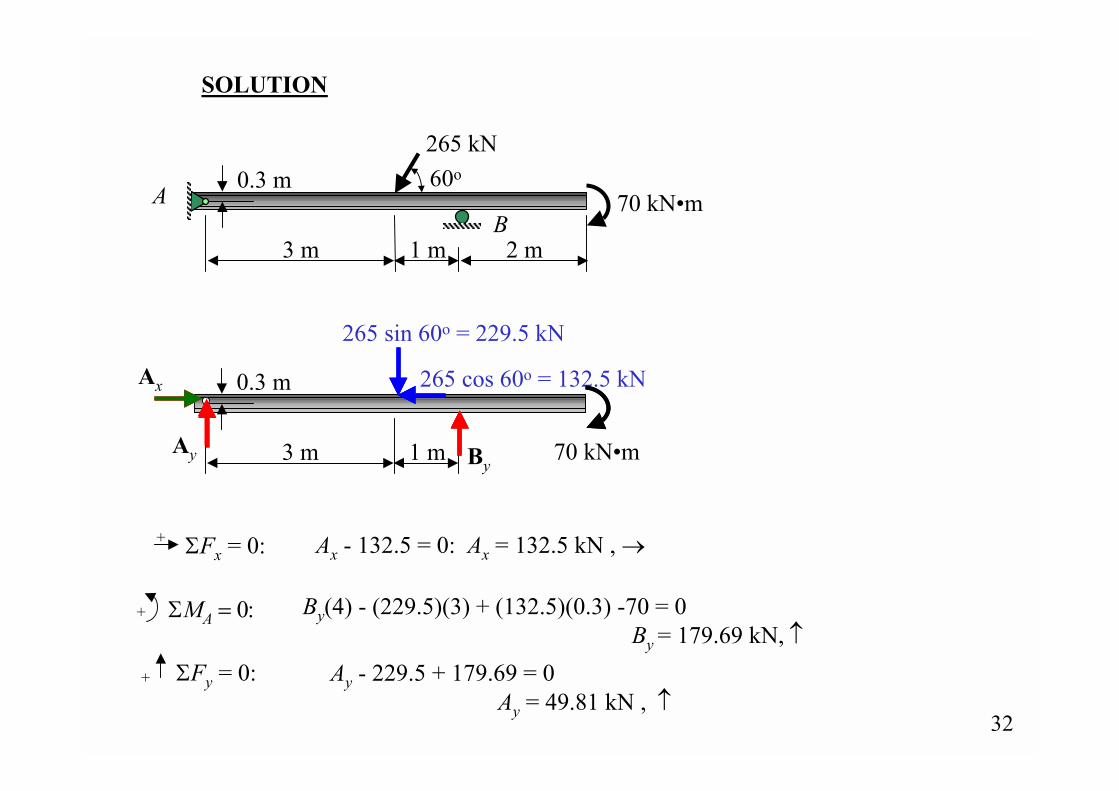
SOLUTION
+ ΣMA = 0: By(4) - (229.5)(3) + (132.5)(0.3) -70 = 0 By = 179.69 kN, ↑
ΣFy = 0:+ Ay - 229.5 + 179.69 = 0 Ay = 49.81 kN , ↑
ΣFx = 0:+ Ax - 132.5 = 0: Ax = 132.5 kN , →
3 m 1 m 70 kN�m
0.3 m
Ay
Ax
By
265 cos 60o = 132.5 kN
265 sin 60o = 229.5 kN
3 m 1 m 2 m
70 kN�m
265 kN60o0.3 mA
B

33
Example 2-6
Determine the reactions on the beam shown.
A
15 kN/m
5 kN/m
12 m
34
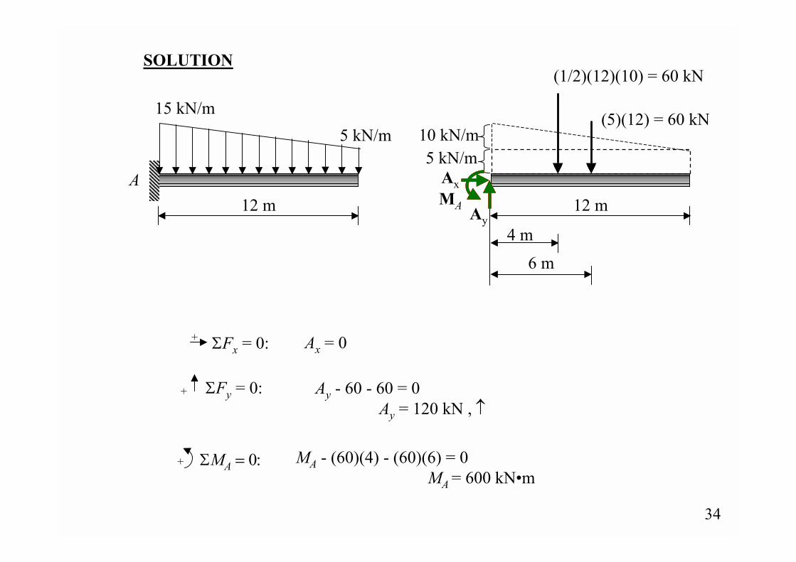
SOLUTION
A
15 kN/m5 kN/m
12 m
ΣFx = 0:+ Ax = 0
ΣFy = 0:+ Ay - 60 - 60 = 0 Ay = 120 kN , ↑
+ ΣMA = 0: MA - (60)(4) - (60)(6) = 0 MA = 600 kN�m
12 m
10 kN/m
(1/2)(12)(10) = 60 kN
4 m
6 m
(5)(12) = 60 kN
5 kN/mAx
Ay
MA
35
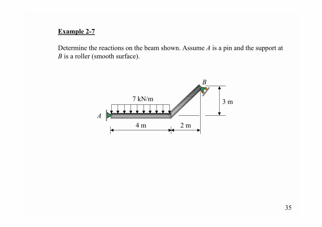
Example 2-7
Determine the reactions on the beam shown. Assume A is a pin and the support atB is a roller (smooth surface).
A
3 m
2 m4 m
7 kN/m
B
36
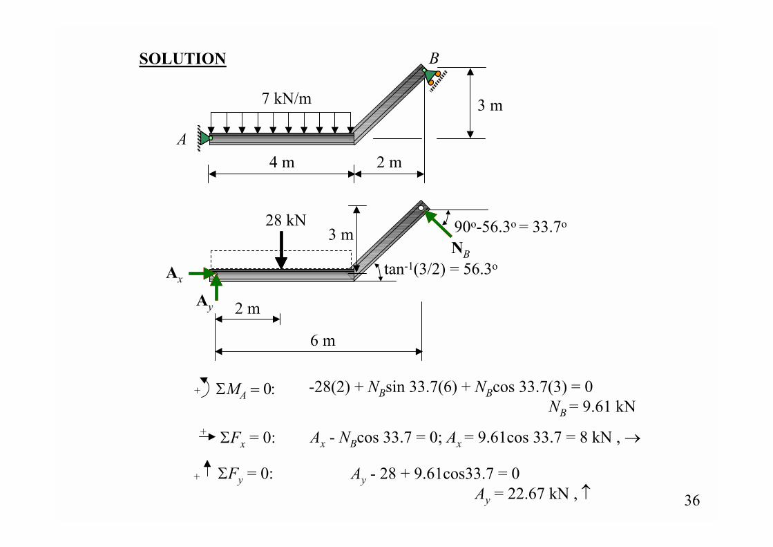
SOLUTION
+ ΣMA = 0: -28(2) + NBsin 33.7(6) + NBcos 33.7(3) = 0 NB = 9.61 kN
ΣFx = 0:+ Ax - NBcos 33.7 = 0; Ax = 9.61cos 33.7 = 8 kN , →
ΣFy = 0:+ Ay - 28 + 9.61cos33.7 = 0 Ay = 22.67 kN , ↑
tan-1(3/2) = 56.3oAx
Ay
NB
90o-56.3o = 33.7o28 kN
2 m
6 m
3 m
A
3 m
2 m4 m
7 kN/m
B
37
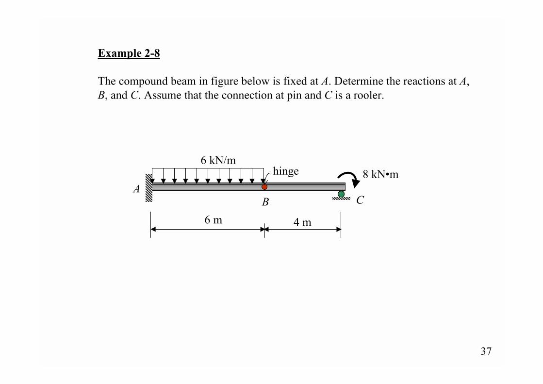
Example 2-8
The compound beam in figure below is fixed at A. Determine the reactions at A,B, and C. Assume that the connection at pin and C is a rooler.
hingeA
B C
6 m 4 m
6 kN/m8 kN�m
38
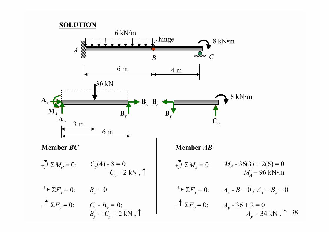
8 kN�m
Cy
Bx
By
+ ΣMA = 0:
Member AB
ΣFx = 0:+
ΣFy = 0:+
MA - 36(3) + 2(6) = 0 MA = 96 kN�m
Ax - B = 0 ; Ax = Bx = 0
Ay - 36 + 2 = 0 Ay = 34 kN , ↑
BxAx
Ay
MA
36 kN
3 m6 m
By
Cy - By = 0; By = Cy = 2 kN , ↑
+ ΣMB = 0:
Member BC
ΣFx = 0:+
ΣFy = 0:+
Cy(4) - 8 = 0 Cy = 2 kN , ↑
Bx = 0
SOLUTION
hingeA
B C
6 m 4 m
6 kN/m8 kN�m
39
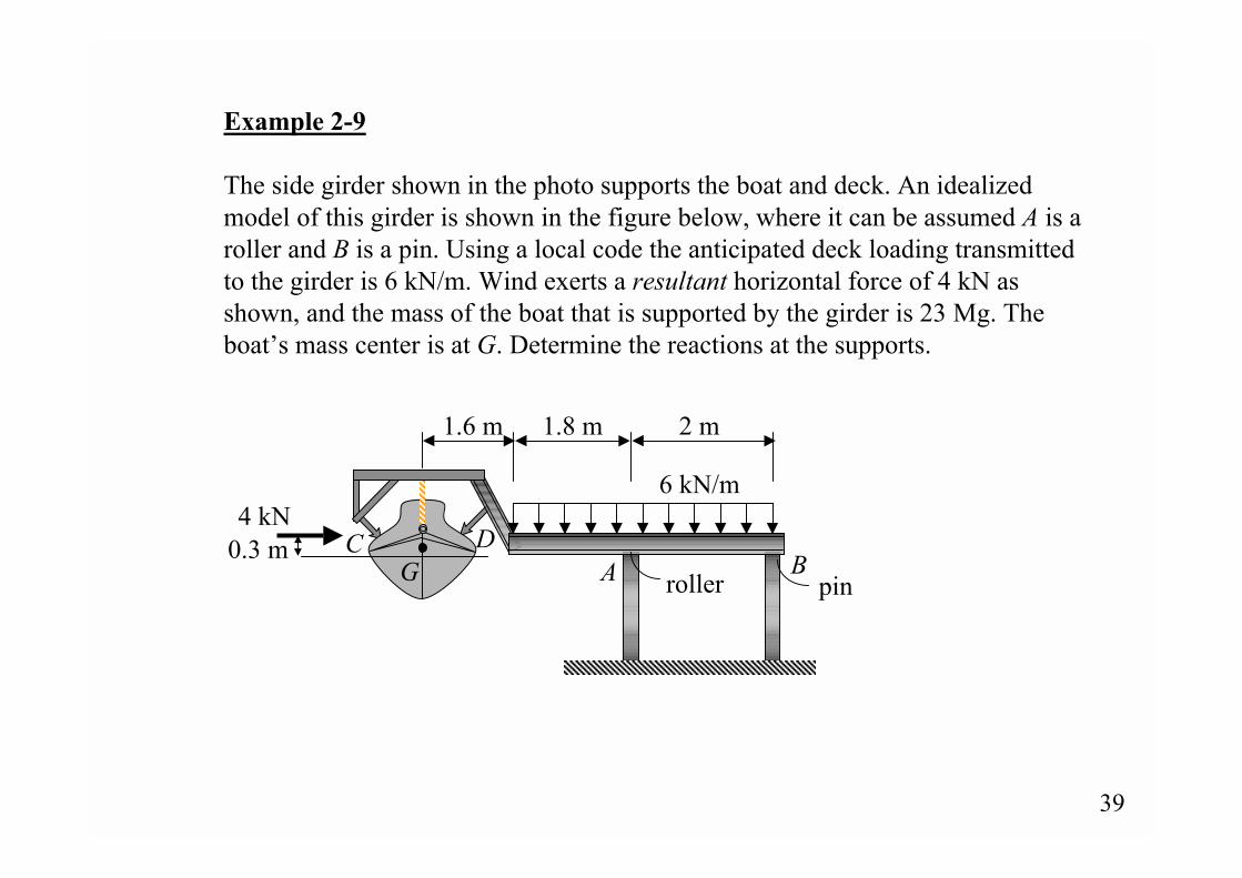
Example 2-9
The side girder shown in the photo supports the boat and deck. An idealizedmodel of this girder is shown in the figure below, where it can be assumed A is aroller and B is a pin. Using a local code the anticipated deck loading transmittedto the girder is 6 kN/m. Wind exerts a resultant horizontal force of 4 kN asshown, and the mass of the boat that is supported by the girder is 23 Mg. Theboat�s mass center is at G. Determine the reactions at the supports.
6 kN/m
1.6 m 1.8 m 2 m
4 kN0.3 m
A BC D
G roller pin
40
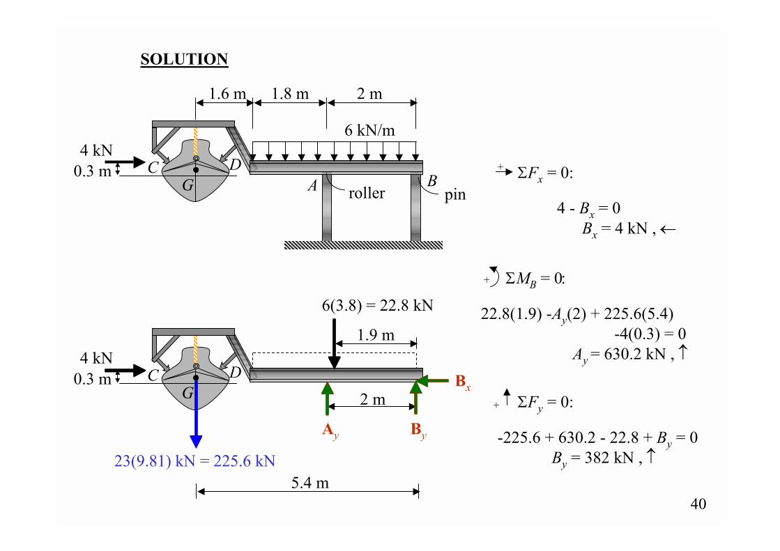
4 kN0.3 m C D
G
By
Bx
6(3.8) = 22.8 kN
1.9 m
Ay
2 m
23(9.81) kN = 225.6 kN5.4 m
+ ΣMB = 0:
6 kN/m
1.6 m 1.8 m 2 m
4 kN0.3 m
A BC D
G
SOLUTION
ΣFx = 0:+
ΣFy = 0:+
4 - Bx = 0 Bx = 4 kN , ←
22.8(1.9) -Ay(2) + 225.6(5.4) -4(0.3) = 0
Ay = 630.2 kN , ↑
-225.6 + 630.2 - 22.8 + By = 0 By = 382 kN , ↑
roller pin
41
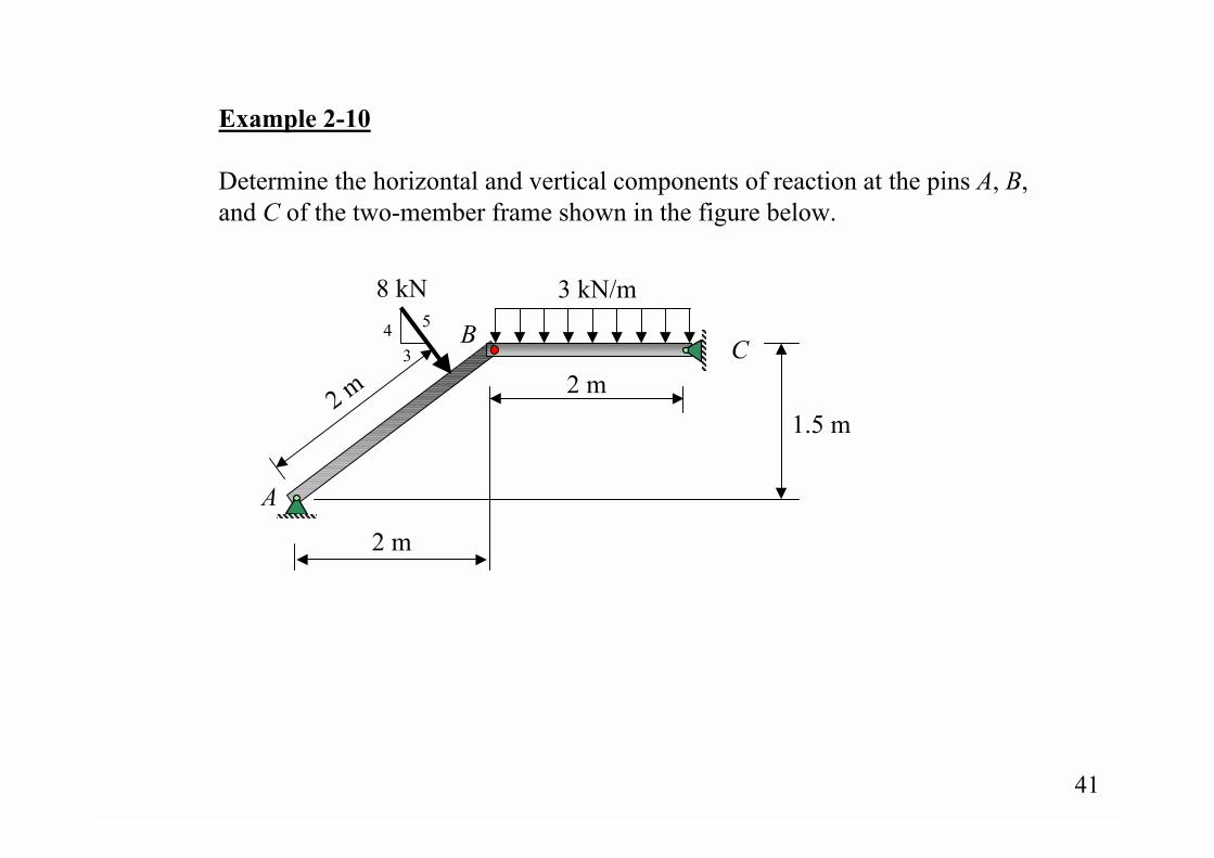
Example 2-10
Determine the horizontal and vertical components of reaction at the pins A, B,and C of the two-member frame shown in the figure below.
8 kN
2 m
3 kN/m
A
B C2 m
2 m
1.5 m
43
5
42
6 kN
1 m 1 m
8 kN
2 m
1.5 m
Bx
By
Ax
Ay
Cx
Cy
Bx
By ΣFy = 0:+
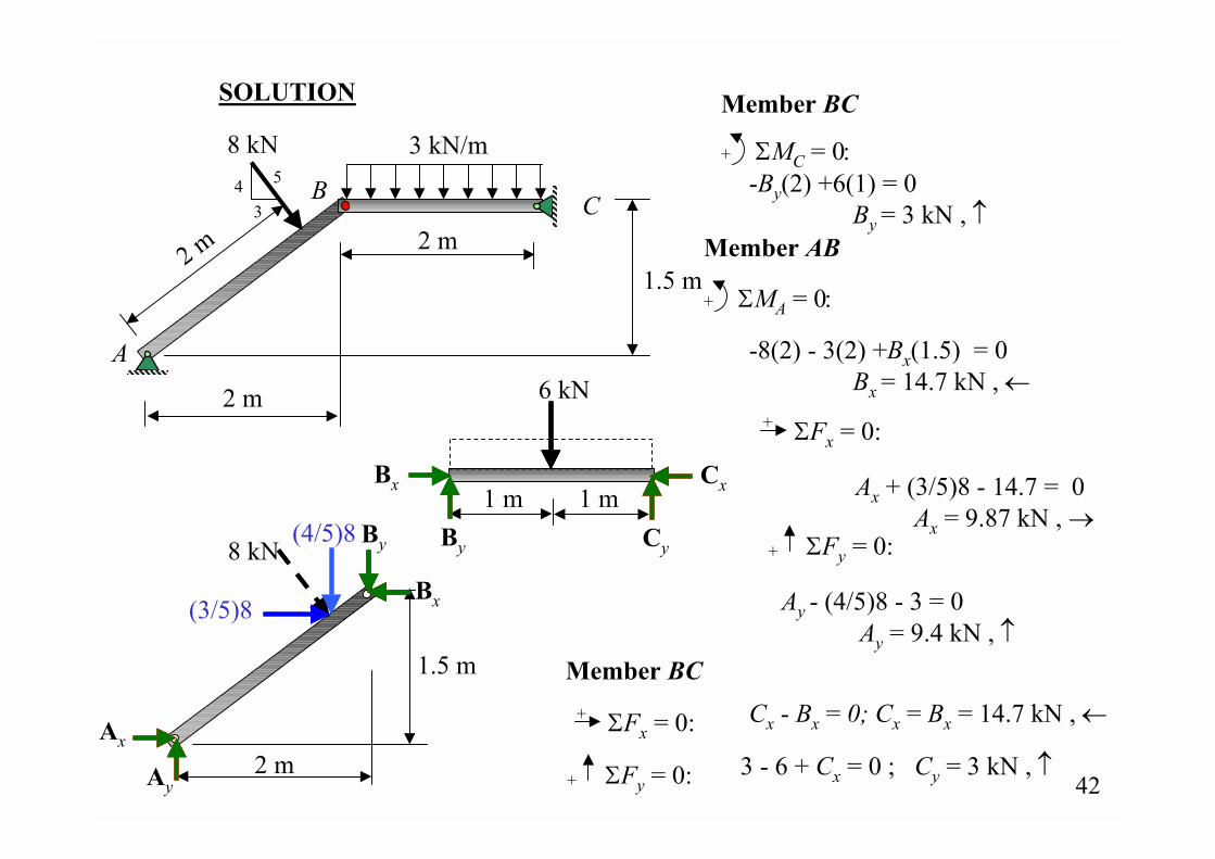
+ ΣMA = 0:
Member AB
+ ΣMC = 0:
Member BC
(3/5)8
SOLUTION
ΣFx = 0:+
Member BC
ΣFx = 0:+
ΣFy = 0:+
(4/5)8
-By(2) +6(1) = 0 By = 3 kN , ↑
-8(2) - 3(2) +Bx(1.5) = 0 Bx = 14.7 kN , ←
Ax + (3/5)8 - 14.7 = 0 Ax = 9.87 kN , →
Cx - Bx = 0; Cx = Bx = 14.7 kN , ←
3 - 6 + Cx = 0 ; Cy = 3 kN , ↑
Ay - (4/5)8 - 3 = 0 Ay = 9.4 kN , ↑
8 kN
2 m
3 kN/m
A
B C2 m
2 m
1.5 m
43
5
43
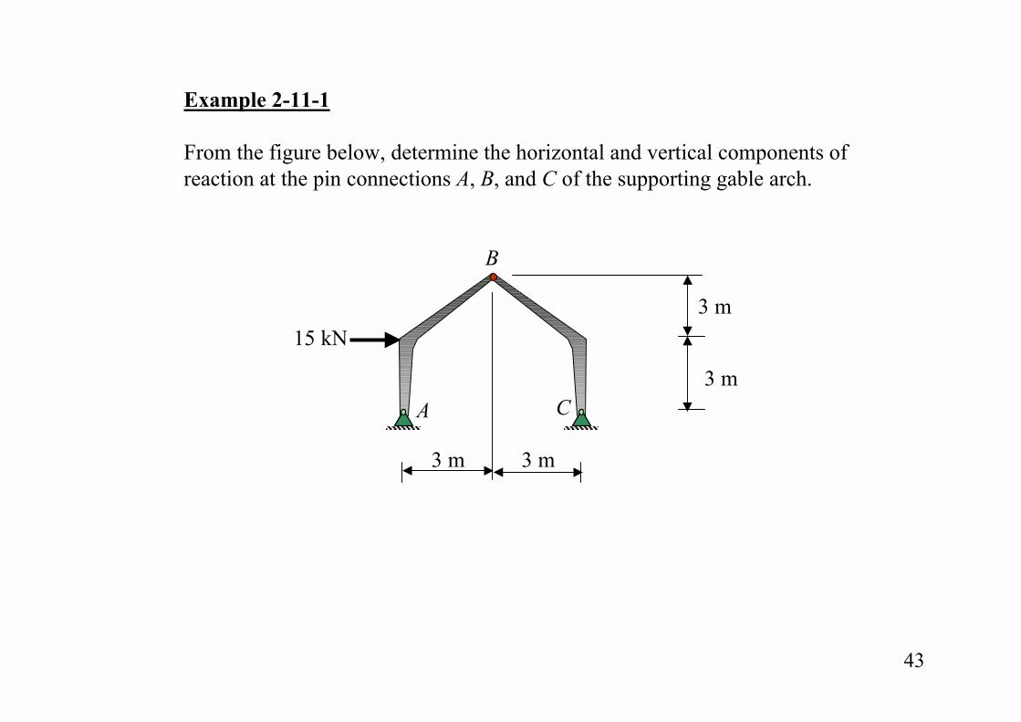
Example 2-11-1
From the figure below, determine the horizontal and vertical components ofreaction at the pin connections A, B, and C of the supporting gable arch.
A
B
C
3 m
3 m
3 m 3 m
15 kN
44
A
B
C
3 m
3 m
3 m 3 m
15 kN
SOLUTION
Ax
Ay
Cx
Cy
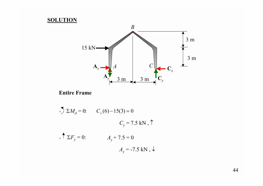
+ ΣMA = 0:
Entire Frame
0)3(15)6( =−yC
ΣFy = 0:+ Ay + 7.5 = 0
Ay = -7.5 kN , ↓
Cy = 7.5 kN , ↑
45
B
C
3 m
3 m
3 m
Cx
7.5 kN
A
B
3 m
15 kN
Ax
3 m
3 m
7.5 kN
Bx
By
Bx
By
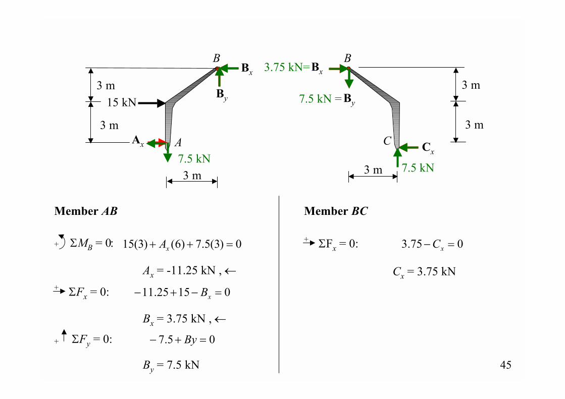
Member BC
ΣFx = 0:+ 075.3 =− xC+ ΣMB = 0:
Member AB
0)3(5.7)6()3(15 =++ xA
ΣFx = 0:+ 01525.11 =−+− xB
ΣFy = 0:+ 05.7 =+− By
Ax = -11.25 kN , ←
Bx = 3.75 kN , ←
By = 7.5 kN
3.75 kN=
7.5 kN =
Cx = 3.75 kN
46
2 m2 m
3 m
3 m
4 m4 m 3 m
3 mwind
A
B
C
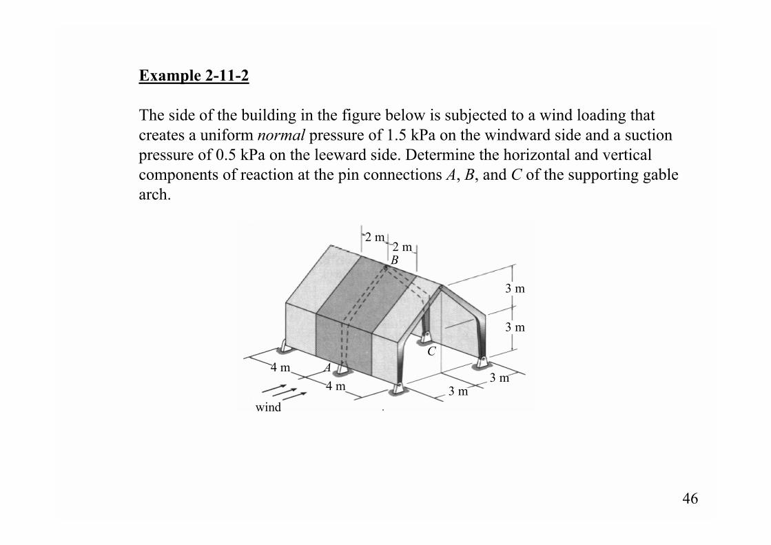
Example 2-11-2
The side of the building in the figure below is subjected to a wind loading thatcreates a uniform normal pressure of 1.5 kPa on the windward side and a suctionpressure of 0.5 kPa on the leeward side. Determine the horizontal and verticalcomponents of reaction at the pin connections A, B, and C of the supporting gablearch.
47
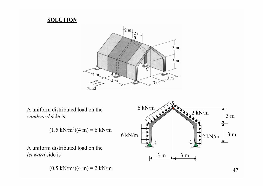
SOLUTION
2 m2 m
3 m
3 m
4 m4 m 3 m
3 mwind
A
B
C
A uniform distributed load on the windward side is
(1.5 kN/m2)(4 m) = 6 kN/m
A uniform distributed load on the leeward side is
(0.5 kN/m2)(4 m) = 2 kN/m
6 kN/m
6 kN/m
2 kN/m
2 kN/mA
B
C
3 m
3 m
3 m 3 m
48
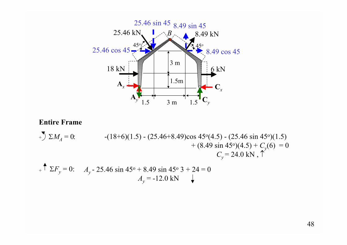
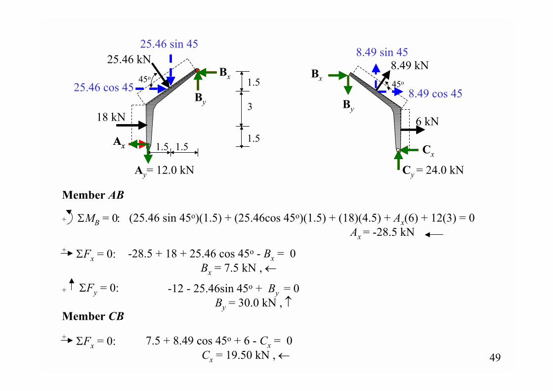
+ ΣMA = 0:
Entire Frame
ΣFy = 0:+
B
18 kN
25.46 kN
6 kN
8.49 kN
Ax
Ay
45o
25.46 sin 45
25.46 cos 45 45o
8.49 cos 45
8.49 sin 45
Cx
Cy1.5 3 m 1.5
3 m
1.5m
-(18+6)(1.5) - (25.46+8.49)cos 45o(4.5) - (25.46 sin 45o)(1.5)+ (8.49 sin 45o)(4.5) + Cy(6) = 0
Cy = 24.0 kN , ↑
Ay - 25.46 sin 45o + 8.49 sin 45o 3 + 24 = 0 Ay = -12.0 kN
49
6 kN
8.49 kN45o
8.49 cos 45
8.49 sin 45
Cx
Cy = 24.0 kN
18 kN
25.46 kN
Ax
Ay= 12.0 kN
45o
25.46 sin 45
25.46 cos 45
Ax
Bx
By
Bx
By
+ ΣMB = 0:
Member AB
1.51.5
3
1.5
1.5
ΣFx = 0:+
(25.46 sin 45o)(1.5) + (25.46cos 45o)(1.5) + (18)(4.5) + Ax(6) + 12(3) = 0 Ax = -28.5 kN
ΣFy = 0:+
ΣFx = 0:+Member CB
7.5 + 8.49 cos 45o + 6 - Cx = 0Cx = 19.50 kN , ←
-28.5 + 18 + 25.46 cos 45o - Bx = 0Bx = 7.5 kN , ←
-12 - 25.46sin 45o + By = 0 By = 30.0 kN , ↑
50
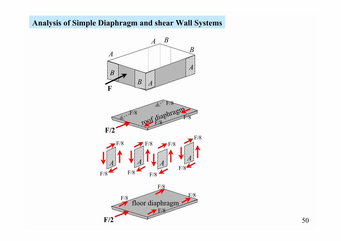
roof diaphragm
floor diaphragm
ABB
A
A B
A
B
F
Analysis of Simple Diaphragm and shear Wall Systems
F/8F/8
F/8
F/8
A
F/8
F/8
A
F/8
F/8A
F/8
F/8
A
F/8
F/8
F/2
F/2
F/8
F/8F/8
F/8
51
AB
BA
CD
CD
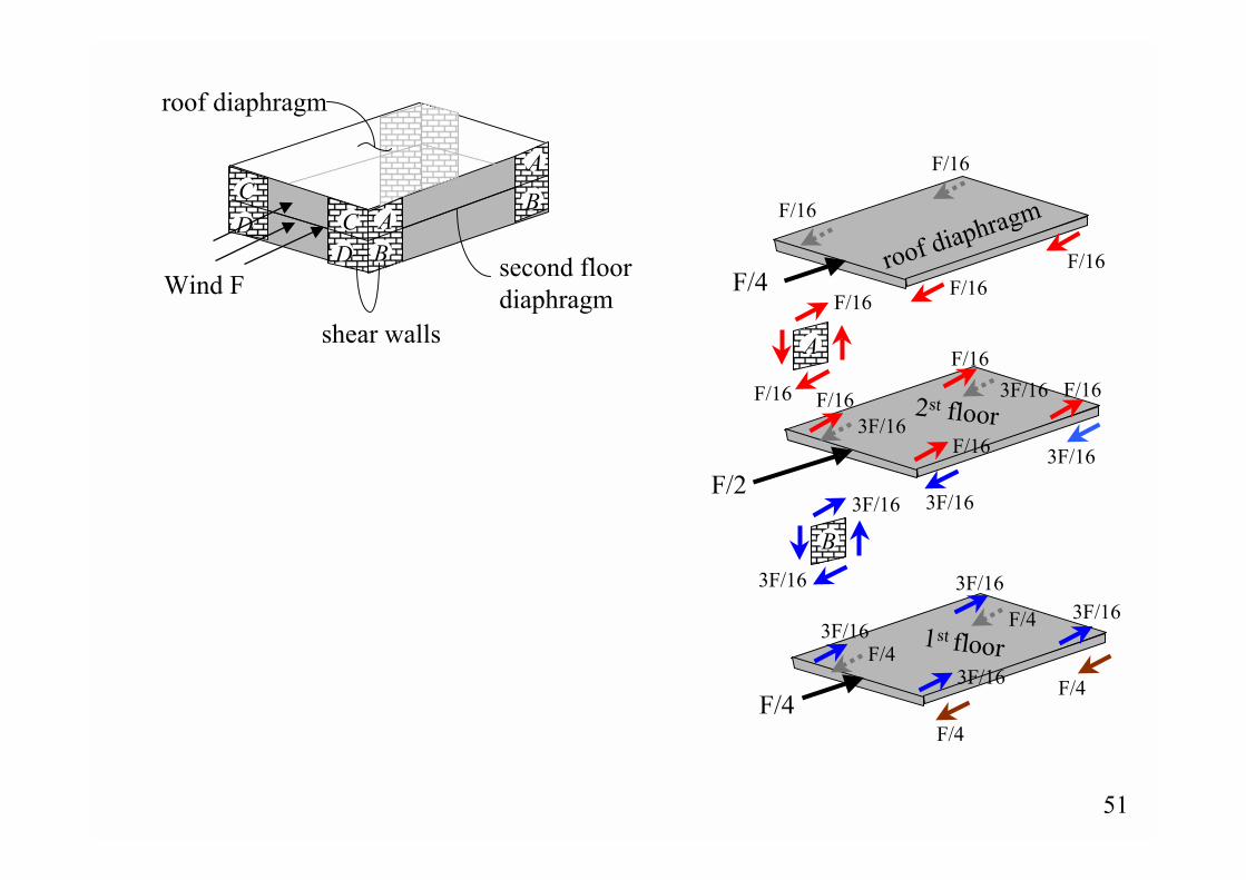
Wind Fsecond floor diaphragm
shear walls
roof diaphragm
2st floor
1st floor
roof diaphragm
F/4
F/4
F/2
F/16
F/16
A
F/16
F/16F/16
F/16
3F/16
3F/163F/16
3F/16
3F/16
3F/16
B
F/16F/16
F/16
F/16
3F/16
3F/163F/16
3F/16
F/4
F/4
F/4
F/4

52
Example 2-12
Assume the wind loading acting on one side of a two-story building is as shownin the figure below. If shear walls are located at each of the corners as shown andflanked by columns, determine the shear in each panel located between the floorsand the shear along the columns.
30 m 20 m
1.2 kPa
0.8 kPa
3 m 3 m
AB
BA
CD
CD
4 m4 m
53
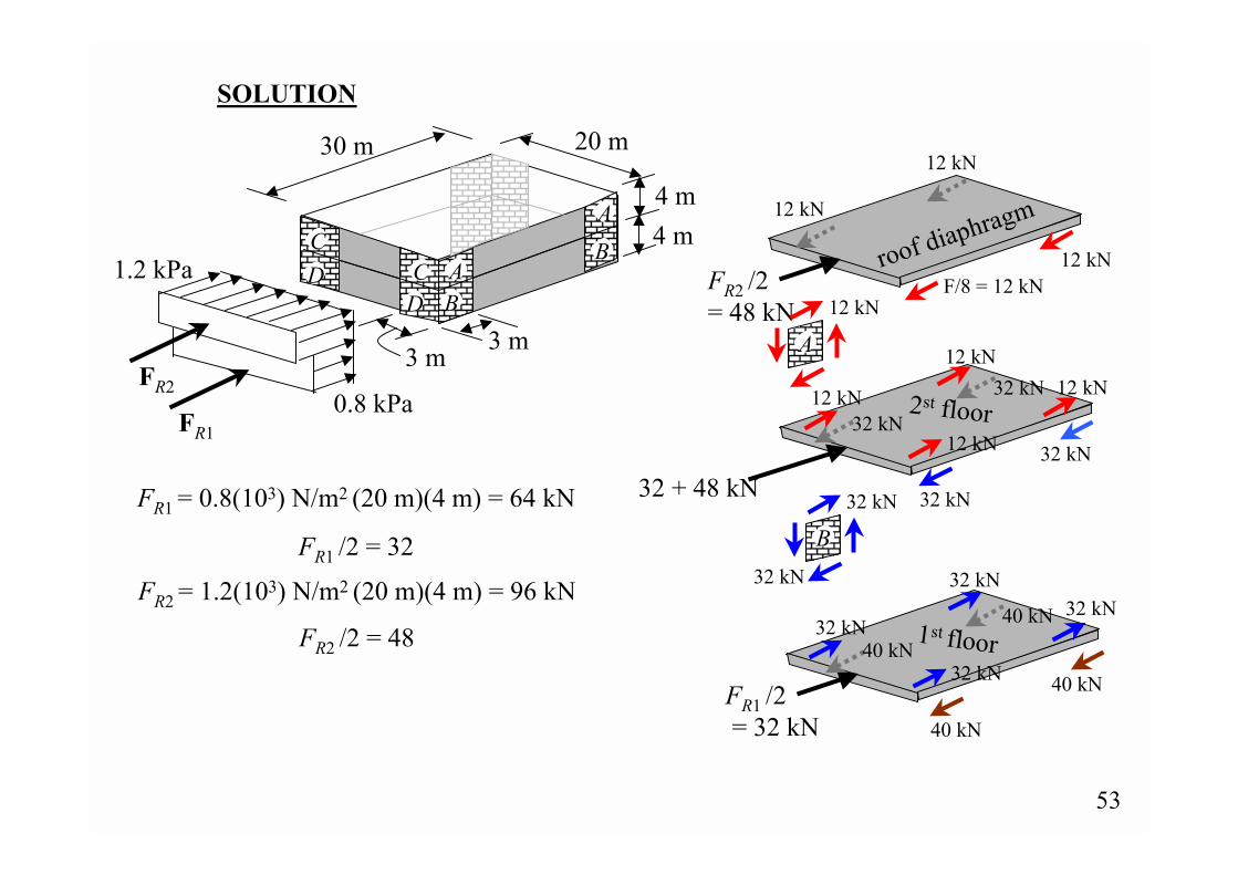
SOLUTION
30 m 20 m
1.2 kPa
0.8 kPa
3 m 3 m
AB
BA
CD
CD
FR1 = 0.8(103) N/m2 (20 m)(4 m) = 64 kN
FR2 = 1.2(103) N/m2 (20 m)(4 m) = 96 kN
FR1 /2 = 32
FR2 /2 = 48
2st floor
1st floor
roof diaphragm
FR1 /2 = 32 kN
32 + 48 kN
FR2 /2 = 48 kN
F/8 = 12 kN12 kN
12 kN
12 kN
12 kN
A
12 kN
12 kN12 kN
12 kN
32 kN
32 kN32 kN
32 kN
32 kN
32 kN32 kN
32 kN
32 kN
32 kN
B
40 kN
40 kN
40 kN
40 kN
4 m4 m
FR1
FR2
54
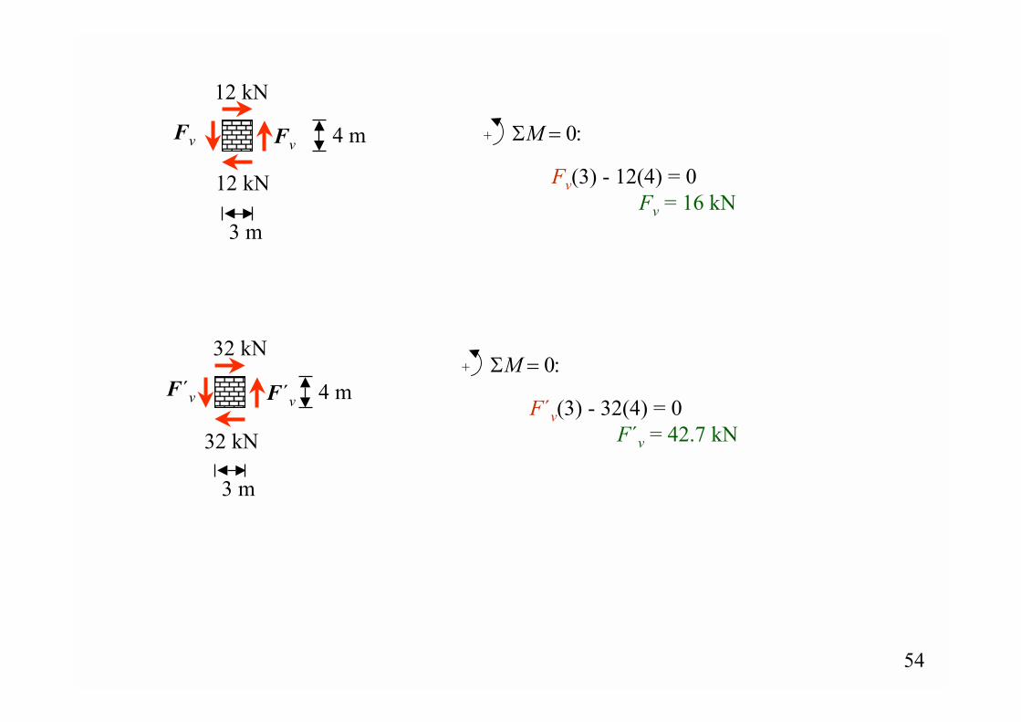
FvFv
3 m
4 m
12 kN
12 kN
+ ΣM = 0:
Fv(3) - 12(4) = 0Fv = 16 kN
+ ΣM = 0:
F´v(3) - 32(4) = 0F´v = 42.7 kN
F´v
3 m
4 m
32 kN
32 kN
F´v