analysis of the regenerative braking system for a...
TRANSCRIPT

8
Analysis of the Regenerative Braking System for a Hybrid Electric Vehicle
using Electro-Mechanical Brakes
Ki Hwa Jung, Donghyun Kim, Hyunsoo Kim and Sung-Ho Hwang Sungkyunkwan University
Republic of Korea
1. Introduction
In the future, automobile makers will be required to produce new technologies that reduce
automotive emissions while still satisfying the ever increasing performance demand of
drivers. Active safety control systems such as Anti-lock Brake System (ABS), Electronic
Braking force Distribution (EBD), Traction Control System (TCS) and Electronic Stability
Program (ESP) need to improve their existing braking functions in order to be truly effective
in improving driving safety. Therefore, brake systems will need to be faster and more
sophisticated when controlling braking forces at the wheels. In addition, smaller pedal
pressure and reduced stroke will be required to produce a larger braking force. With ABSs,
the surge and fluctuation of pedal force gives the driver an uncomfortable feeling. These are
only a few of the problems and technical limitations of current braking control systems
(Semm et al., 2003, Peng et al., 2008).
Figure 1 shows the development trend of braking control systems. The future development
in braking technology will progress towards brake-by-wire; therefore, brake manufacturers
will need to take a greater interest in the development of Electro-Mechanical Brake (EMB)
systems (Line et al., 2004, Emereole & Good, 2005)
EMB systems replace conventional hydraulic braking systems by eliminating the hydraulics
and replacing them with electrical components. They are able to eliminate the large vacuum
booster found in conventional systems, which helps to simplify production of right- and
left-hand drive vehicle variants. When compared to conventional braking systems, EMB
systems offer increased flexibility for components placement by totally eliminating the
hydraulic system (Nakamura et al., 2002). Figure 2 shows the comparison of EMB and EHB
(Electro-Hydraulic Brake) systems.
This paper investigates the modeling and simulation of EMB systems for Hybrid Electric
Vehicles (HEV). The HEV powertrain was modeled to include the internal combustion
engine, electric motor, battery, and transmission. The performance simulation for the
regenerative braking system of the HEV was performed using MATLAB/Simulink. The
control performance of the EMB system was evaluated via simulation of the regenerative
braking of the HEV during various driving conditions.
Source: Urban Transport and Hybrid Vehicles, Book edited by: Seref Soylu, ISBN 978-953-307-100-8, pp. 192, September 2010, Sciyo, Croatia, downloaded from SCIYO.COM
www.intechopen.com

Urban Transport and Hybrid Vehicles
152
Fig. 1. Development trend of brake control systems
Fig. 2. Comparison of EMB and EHB systems
www.intechopen.com
Analysis of the Regenerative Braking System for a Hybrid Electric Vehicle using Electro-Mechanical Brakes
153
2. HEV powertrain modeling
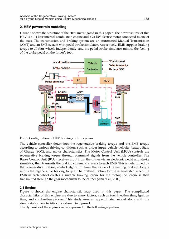
Figure 3 shows the structure of the HEV investigated in this paper. The power source of this HEV is a 1.4 liter internal combustion engine and a 24 kW electric motor connected to one of the axes. The transmission and braking system are an Automated Manual Transmission (AMT) and an EMB system with pedal stroke simulator, respectively. EMB supplies braking torque to all four wheels independently, and the pedal stroke simulator mimics the feeling of the brake pedal on the driver’s foot.
Fig. 3. Configuration of HEV braking control system
The vehicle controller determines the regenerative braking torque and the EMB torque according to various driving conditions such as driver input, vehicle velocity, battery State of Charge (SOC), and motor characteristics. The Motor Control Unit (MCU) controls the regenerative braking torque through command signals from the vehicle controller. The Brake Control Unit (BCU) receives input from the driver via an electronic pedal and stroke simulator, then transmits the braking command signals to each EMB. This is determined by the regenerative braking control algorithm from the value of remaining braking torque minus the regenerative braking torque. The braking friction torque is generated when the EMB in each wheel creates a suitable braking torque for the motor; the torque is then transmitted through the gear mechanism to the caliper (Ahn et al., 2009).
2.1 Engine
Figure 4 shows the engine characteristic map used in this paper. The complicated characteristics of this engine are due to many factors, such as fuel injection time, ignition time, and combustion process. This study uses an approximated model along with the steady state characteristic curve shown in Figure 4. The dynamics of the engine can be expressed in the following equation:
www.intechopen.com

Urban Transport and Hybrid Vehicles
154
( , )e e e e loss clutchJ T T Tω θ ω= − −$ (1)
where Je is the rotational inertia, ωe is the engine rpm, Te is the engine torque, Tloss is loss in engine torque, and Tclutch is the clutch torque.
020
4060
80100
0
2000
4000
60000
20
40
60
80
100
120
Throttle Position[%]Engine Speed[rpm]
Torq
ue[N
m]
Fig. 4. Engine characteristic map
2.2 Motor
Figure 5 shows the characteristic curve of the 24 kW BLDC motor used in this study. In driving mode, the motor is used as an actuator; however, in the regenerative braking mode, it functions as a generator.
01000
20003000
40005000
6000
-100
-50
0
50
100
60
80
100
120
Motor Speed [rpm]
Motor Torque[Nm]
Eff
icie
ncy[%
]
Fig. 5. Characteristic map of the motor
www.intechopen.com

Analysis of the Regenerative Braking System for a Hybrid Electric Vehicle using Electro-Mechanical Brakes
155
When the motor is functioning as an actuator, the torque can be approximated using the following 1st order equation:
_
m
m desired mm
T
T TdT
dt τ−= (2)
where Tm is the motor torque, Tm_desired is the required torque, and mTτ is the time constant
for the motor.
2.3 Battery
The battery should take into account the relationship between the State Of Charge (SOC) and its charging characteristics. In this paper, the input/output power and SOC of the battery are calculated using the internal resistance model of the battery. The internal resistance is obtained through experiments on the SOC of the battery. The following equations describe the battery’s SOC at discharge and charge.
• At discharge:
1 1( , ) ( )i
i
t m
dis m A a atSOC SOC Q i i t dtη τ+− −= − ∫ (3)
• At charge:
1 ( )i
i
t m
chg m atSOC SOC Q i t dt
+−= + ∫ (4)
where disSOC is the electric discharge quantity at discharge mode, chgSOC is the charge
quantity of the battery, mQ is the battery capacity, and ( , )A aiη τ is the battery’s efficiency.
2.4 Automated Manual Transmission
The AMT was modeled to change the gear ratio and rotational inertia that correspond to the
transmission’s gear position. Table 1 shows the gear ratio and reflected rotational inertia
that was used in the developed HEV simulator.
Gear ratio Reflected inertia(kg.m2)
1st 3.615 0.08999
2nd 2.053 0.02903
3rd 1.393 0.00699
4th 1.061 0.00699
5th 0.837 0.00699
Table 1. Gear ratio of automated manual transmission
The output torque relationships with respect to driving mode are described in Table 2. At Zero Emission Vehicle (ZEV) mode, the electric motor is only actuated when traveling
www.intechopen.com

Urban Transport and Hybrid Vehicles
156
below a critical vehicle speed. In acceleration mode, the power ratio of the motor and the engine is selected in order to meet the demands of the vehicle. At deceleration mode, the regenerative braking torque is produced from the electric motor. The above stated control logic is applied only after considering the SOC of the battery.
Mode Torque relation
ZEV EV out motorT T=
Acceleration Hybrid out motor engineT xT yT= +
Deceleration Regen. out regenT T=
• Considering the Battery SOC
• 1x y+ =
Table 2. Output torque relationships with respect to driving mode of AMT-HEV
2.5 Vehicle model
When the engine and the electric motor are operating simultaneously, the vehicle state equation is as follows (Yeo et al., 2002)
2 2 2
2
( )
2 ( )
f t
e m R
t
w e m c t f t f
t
N NT T F
dV R
I J J J N N J NdtM
R
+ −= + + + ++
(5)
where V is the vehicle velocity, Nf is the final differential gear ratio, Nt is the transmission gear ratio, Rt is the radus of the tire, FR is the resistance force, M is the vehicle mass, Iw is the equivalent wheel inertia, and Je, Jm, Jc, and Jt are the inertias of engine, motor, clutch, and transmission, respectively.
3. EMB system
The EMB system is environmentally friendly because it does not use a hydraulic system, but rather a ‘dry’ type Brake–by-wire (BBW) system, which employs an EMB Module (i.e., electric caliper, electro-mechanical disk brake) as the braking module for each wheel. The EMB system is able to provide a large braking force using only a small brake pedal reaction force and a short pedal stroke.
3.1 Structure of EMB system
Motors and solenoids can be considered as the electric actuators for EMB systems. The motor is usually chosen as an actuator of the EMB system because the solenoid produces such a small force corresponding to the current input and has such a narrow linear control range that it is unsuitable. In order to generate the proper braking force, Brushless DC
www.intechopen.com

Analysis of the Regenerative Braking System for a Hybrid Electric Vehicle using Electro-Mechanical Brakes
157
(BLDC) and induction motors are used due to their excellent output efficiency and remarkable durability, respectively. Figure 6 shows a schematic diagram of an EMB system.
Fig. 6. Schematic diagram of the EMB system
Friction forces are the result of changing resistance of the motor coil and the rigidity of the
reduction gear due to temperature fluctuations. To compensate for friction, the control
structure for EMB torque adopts a cascade loop. The loop has a low level control logic
consisting of the current and velocity control loop shown in Figure 7. This structure requires
particularly expensive sensors to measure the clamping force and braking torque; therefore,
this paper uses a technique that estimates their values by sensing the voltage, current and
position of the DC motor based on the dynamic model of the EMB (Schwarz et al., 1999).
Fig. 7. Control structure of EMB system
www.intechopen.com

Urban Transport and Hybrid Vehicles
158
3.2 Simulation model of EMB system
Figure 8 shows the EMB performance analysis simulator developed in this paper. Force, speed, and electric motor current are fed back via the cascaded loops and controlled by the PID controller.
Fig. 8. EMB simulation model
Figure 9 shows the response characteristics of the EMB system. The step response in the time domain is shown at a brake force command of 14 kN.
0
2000
4000
6000
8000
10000
12000
14000
16000
0 0.2 0.4 0.6 0.8 1
Time [sec]
Cla
mp
ing
Fo
rce
[N
]
Fig. 9. EMB step response to a force command of 14 kN
www.intechopen.com

Analysis of the Regenerative Braking System for a Hybrid Electric Vehicle using Electro-Mechanical Brakes
159
4. Regenerative braking control algorithm
In conventional vehicles, the energy required to reduce velocity would normally be dissipated and wasted as heat during braking. On the other hand, HEVs have a regenerative braking system that can improve fuel economy. In an HEV, the braking torque is stored in a battery and regenerated through the electric motor/generator (Yaegashi et al., 1998). In this paper, the regenerative braking torque and EMB torque were determined according to the demand of the driver, the characteristics of the electric motor, the SOC of the battery, and the vehicle’s velocity. When the regenerative braking power is bigger than the driver’s intended braking power, the brake system generates only the regenerative braking torque. When this occurs, the BCU should control the magnitude of regenerative braking torque from the regenerative electric power of motor/generator in order to maintain a brake feeling similar to that of a conventional vehicle (Gao et al., 1999). In this paper, the control algorithm for maximizing regenerative braking torque is performed in order to increase the quantity of battery charge.
4.1 Decision logic of regenerative braking torque
Figure 10 shows the flow chart of the control logic for regenerative braking torque.
Fig. 10. Regenerative braking control logic flow chart
First, sensing the driver’s demand for braking, it calculates the required brake force of the front and rear wheels by using the brake force curve distribution. Then, the logic decides whether the braking system should perform regenerative braking, depending on the states of the accelerator, the brake, the clutch, and the velocity of both engine and vehicle, and on the fail signal. If regenerative braking is available, the optimal force of regenerative braking will subsequently be determined according to the battery’s SOC and the speed of the motor. Finally, the algorithm will calculate the target regenerative braking torque. In a situation
www.intechopen.com

Urban Transport and Hybrid Vehicles
160
where the fluctuation of the regenerative braking causes a difference of torque, the response time delay compensation control of the front wheel could be used to minimize the fluctuation of the target brake force. After the target braking torque is determined, the remainder of the difference between target braking torque and the regenerative braking torque will be transmitted via the EMB system.
4.2 Limitation logic of regenerative braking torque Overcharging the battery during regenerative braking reduces battery durability. Therefore, when the SOC of the battery is in the range of 50%-70%, the logic applies the greatest regenerative torque; however, when the SOC is above 80%, it does not perform regeneration (Yeo et al., 2004).
5. HEV performance simulator using MATLAB/Simulink
The brake performance simulator was created for validating the regenerative braking control logic of the parallel HEV. The modeling of the HEV powertrain (including the engine, the motor, the battery, the automated manual transmission, and EMB) was performed, and the control algorithm for regenerative braking was developed using MATLAB/Simulink. Figure 11 illustrates the AMT-HEV simulator.
Fig. 11. AMT-HEV simulator with EMB
www.intechopen.com

Analysis of the Regenerative Braking System for a Hybrid Electric Vehicle using Electro-Mechanical Brakes
161
6. Simulation results
The simulation results for the Federal Urban Drive Schedule (FUDS) mode using the performance simulator are shown in Figure 12. According to Figure 12, the brake pedal and accelerator positions are changing relative to the drive mode. Subsequently, the vehicle’s velocity successfully chases the drive mode. The torque of the engine and the motor is illustrated in the figure. The graph of battery SOC adequately shows charging state by regenerative braking during deceleration.
Fig. 12. Simulation results for FUDS mode
7. Conclusion
In this paper, the performance simulation for a hybrid electric vehicle equipped with an EMB system was conducted. A performance simulator and dynamics models were developed to include such subsystems as the engine, the motor, the battery, AMT, and EMB. The EMB control algorithm that applied the PID control technique was constructed based on cascade control loops composed of the current, velocity, and force control systems. The simulation results for FUDS mode showed that the HEV equipped with an EMB system can regenerate the braking energy by using the proposed regenerative braking control algorithm.
8. References
Ahn, J., Jung, K., Kim, D., Jin, H., Kim, H. and Hwang, S. (2009). Analysis of a regenerative braking system for hybrid electric vehicles using an electro-mechanical brake, Int. J. of Automotive Technology, Vol. 10(No. 2): 229−234.
www.intechopen.com

Urban Transport and Hybrid Vehicles
162
Emereole, O. and Good, M. (2005). The effect of tyre dynamics on wheel slip control using electromechanical brakes. SAE Paper No. 2005-01-0419.
Gao, Y., Chen, L. and Ehsani, M. (1999). Investigation of the effectiveness of regenerative braking for EV and HEV. SAE Paper No. 1999-01-2910.
Kim, D., Hwang, S. and Kim, H. (2008). Vehicle stability enhancement of four-wheel-drive hybrid electric vehicle using rear motor control, IEEE Transactions on Vehicular Technology, Vol. 57(No. 2): 727-735.
Line, C., Manzie, C. and Good, M. (2004). Control of an electromechanical brake for automotive brake-by-wire systems with an adapted motion control architecture. SAE Paper No. 2004-01-2050.
Nakamura, E., Soga, M., Sakaki, A., Otomo, A. and Kobayashi, T. (2002). Development of electronically controlled brake system for hybrid vehicle. SAE Paper No. 2002-01-0900.
Peng, D., Zhang, Y., Yin, C.-L., and Zhang, J.-W. (2008). Combined control of a regenerative braking and antilock braking system for hybrid electric vehicles, Int. J. of Automotive Technology, Vol. 9(No. 6): 749-757.
Schwarz, R., Isermann, R., Bohm, J., Nell, J. and Rieth, P. (1999). Clamping force estimation for a brake-by-wire actuator. SAE Paper No. 1999-01-0482.
Semm, S., Rieth, P., Isermann, R. and Schwarz, R. (2003). Wheel slip control for antilock braking systems using brake-by-wire actuators. SAE Paper No. 2003-01-0325.
Yaegashi, T., Sasaki, S. and Abe, T. (1998). Toyota hybrid system: It's concept and technologies. FISITA F98TP095.
Yeo, H. and Kim, H. (2002). Hardware-in-the-loop simulation of regenerative braking a hybrid electric vehicle. Proc. Instn. Mech. Engrs., Vol. 216: 855-864.
Yeo, H., Song, C., Kim, C. and Kim, H. (2004). Hardware in the loop simulation of hybrid electric vehicle for optimal engine operation by CVT ratio control. Int. J. of Automotive Technology, Vol. 5(No. 3): 201-208.
www.intechopen.com

Urban Transport and Hybrid VehiclesEdited by Seref Soylu
ISBN 978-953-307-100-8Hard cover, 192 pagesPublisher SciyoPublished online 18, August, 2010Published in print edition August, 2010
InTech EuropeUniversity Campus STeP Ri Slavka Krautzeka 83/A 51000 Rijeka, Croatia Phone: +385 (51) 770 447 Fax: +385 (51) 686 166www.intechopen.com
InTech ChinaUnit 405, Office Block, Hotel Equatorial Shanghai No.65, Yan An Road (West), Shanghai, 200040, China
Phone: +86-21-62489820 Fax: +86-21-62489821
This book is the result of valuable contributions from many researchers who work on both technical andnontechnical sides of the field to be remedy for typical road transport problems. Many research results aremerged together to make this book a guide for industry, academia and policy makers.
How to referenceIn order to correctly reference this scholarly work, feel free to copy and paste the following:
Sung-Ho Hwang, Hyunsoo Kim, Donghyun Kim and Kihwa Jung (2010). Analysis of a Regenerative BrakingSystem for a Hybrid Electric Vehicle Using Electro-Mechanical Brakes, Urban Transport and Hybrid Vehicles,Seref Soylu (Ed.), ISBN: 978-953-307-100-8, InTech, Available from: http://www.intechopen.com/books/urban-transport-and-hybrid-vehicles/analysis-of-a-regenerative-braking-system-for-hybrid-electric-vehicles-using-an-electro-mechanical-b