analysis of the velocities in the wake of an azimuthing...
TRANSCRIPT

Analysis of the Velocitiesin the Wake of an Azimuthing Thruster,
using PIV Measurementsand CFD Calculations
Hans Cozijn (MARIN)Rink Hallmann, Arjen Koop

2
Presentation Outline– Background and Objectives– Case Description
– Thruster in Open Water Conditions– Thruster under a Barge
– Model Tests– PIV Measurements– CFD Calculations– Comparison of Results– Conclusions and Recommendations

3
Background
– Thrust degradation effects– Thruster-hull– Thruster-thruster– Thruster-current interaction– Thruster ventilation
"During DP operations the effective force generated by the thrusters can be significantly smaller than what would be expected based on the thrusters' open water characteristics."
4
Objectives of the Present Work
– Improve understanding of the physics related to thruster-interaction (thrust degredation) effects
– Investigate applicability of PIV measurementsfor measurement of thruster wake velocities
– Comparisson of measurements, CFD calculations, and empirical models
– Thruster in Open Water– Thruster under a Barge
– Validation of CFD calculations

5
Case Description
– Case 1 - Thruster in Open Water– Propeller + nozzle– Bollard pull conditions
– Case 2 - Thruster under Barge– Schematical barge shape– Rounded bilge
– (Case 3 - Thruster under Barge with Pontoon)– (Schematical pontoon added)
6
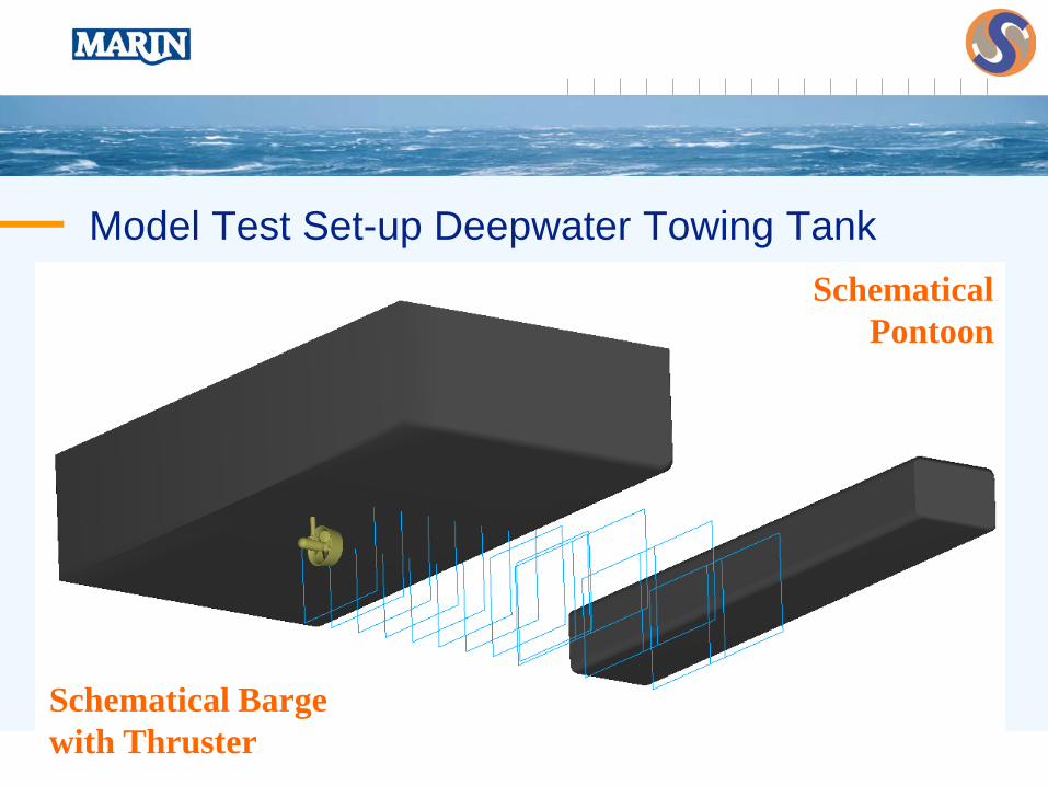
Model Test Set-up Deepwater Towing Tank
Schematical Bargewith Thruster
SchematicalPontoon

7
Model Tests - Measured Quantities
– Propeller Thrust and Torque– (Nozzle Thrust)– Total Thrust Force– Total Force on Barge– Total Force on Schematical Pontoon– Velocity Measurements
at x = 1, 2, 3, 4, 5, 6, 7, 8, 9, 10, 12.5 and 15 x D

8
PIV Measurements
– PIV concept– Particles in water ("seeding")– Illumination by laser sheet– Cameras (2)– Image capturing + data analysis
– MARIN new PIV system (2009)– 3D PIV measurements– Measuring area ~ 24 x 36 cm– Class 4 laser– Traverse system x-y-z– Laser + cameras in single housing

9
Main Principles of PIV
– PIV is a method for determining ‘instant’ velocity vector maps.
– A thin light sheet is generated and the movement of particles inside this light sheet is observed with (one or more) digital cameras
Camera A
Camera B
Light sheet ~4 mm thick

10
PIV System in MARIN's Deepwater Towing Tank

11
PIV System in MARIN's Deepwater Towing Tank

12
Example PIV Measurements - Open Water

13
Results PIV Measurements - Open Water

14
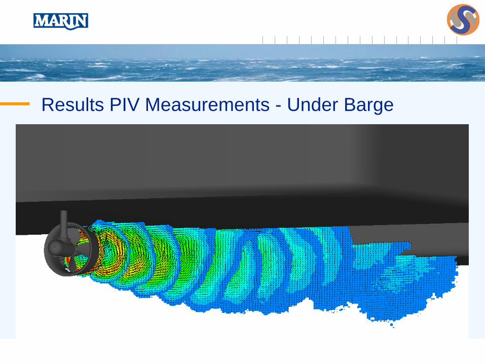
Results PIV Measurements - Under Barge
15
Results PIV Measurements - Under Barge
16
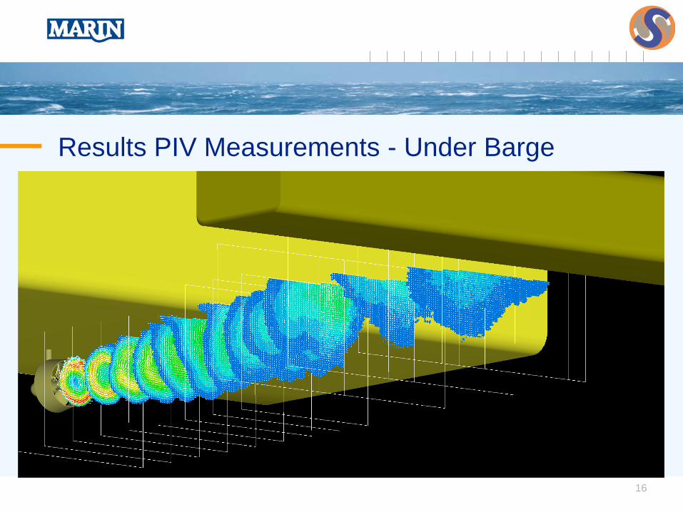
Results PIV Measurements - Under Barge

17
CFD Calculations
– MARIN in-house ReFRESCO code– Reynolds Averaged Navier-Stokes (RANS)– Turbulence models– Finite volume method, allowing use of arbitray grid types– Parallelized code
– Calculation Hardware– Linux cluster 3 (1,184 processors)– Cluster 1 (12 processors), Cluster 2 (256 processors)
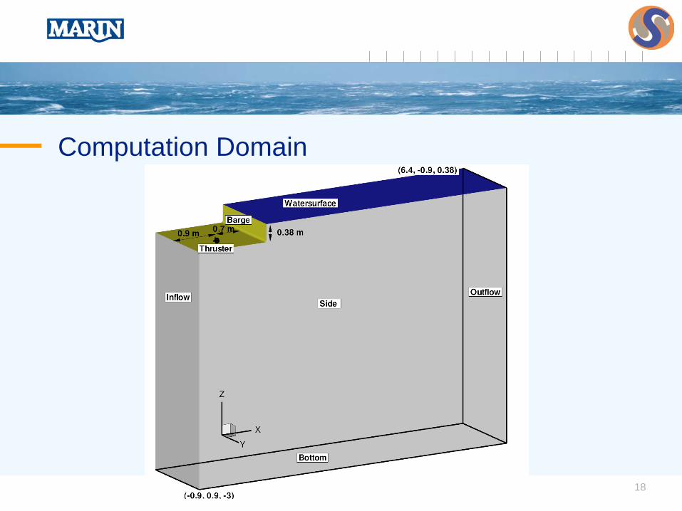
18
Computation Domain
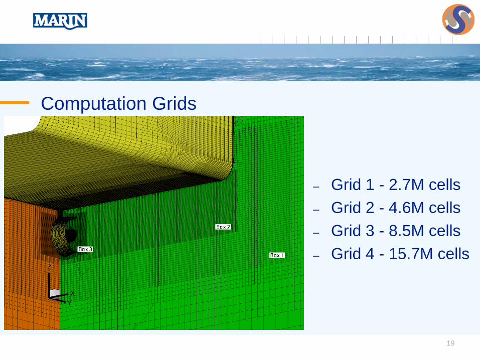
19
Computation Grids
– Grid 1 - 2.7M cells– Grid 2 - 4.6M cells– Grid 3 - 8.5M cells– Grid 4 - 15.7M cells

20
Computation Grids
x/D = 7x/D = 2

21
Computation Grids
Grid 1 (2.7M cells) Grid 4 (15.7M cells)

22
Comparison of Results
– Open Water Conditions– PIV measurements– Nienhuis emperical model
– Thruster under a Barge– PIV measurements– CFD calculations

23
CFD Calculations vs. PIV Measurements
– Differences observed near thruster (x/D = 1 - 5)– Correspondence may be improved
by adjustment of radial thrust distribution
– Better accuracy further down-stream (x/D = 7 - 15)– No numerical dissipation is observed
x/D = 1 x/D = 3 x/D = 7 x/D = 15

24
Model Tests by Nienhuis (LDV measurements)
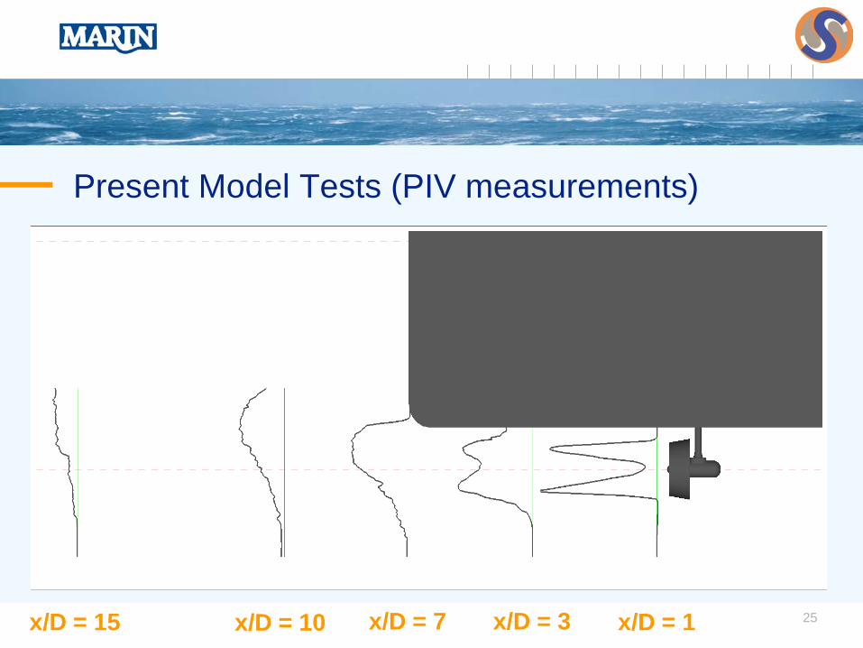
25
Present Model Tests (PIV measurements)
x/D = 1x/D = 3x/D = 7x/D = 15 x/D = 10

26
Conclusions and Recommendations– Conclusions
– PIV measurements can capture the wake flow behinda thruster, including wake development and Coanda effect.
– CFD results represent the observed physics in the wake flow.Better accuracy can be achieved by improved modellingof the radial thrust distribution.
– Recommendations for Further Research– Investigate effect of radial thrust distribution– Investigate effect of rotation and divergence modelling– Investigate effect of nozzle shape– Analysis of more complex configurations
