analytical and experimental investigation of rotary...
TRANSCRIPT
1
ANALYTICAL AND EXPERIMENTAL INVESTIGATION OF ROTARY-VANE TWO-PHASE EXPANDERS IN VAPOR COMPRESSION REFRIGERATION SYSTEMS
By
AHMAD MOHAMED MAHMOUD
A DISSERTATION PRESENTED TO THE GRADUATE SCHOOL OF THE UNIVERSITY OF FLORIDA IN PARTIAL FULFILLMENT
OF THE REQUIREMENTS FOR THE DEGREE OF DOCTOR OF PHILOSOPHY
UNIVERSITY OF FLORIDA
2008

2
© 2008 Ahmad Mohamed Mahmoud

3
I dedicate this work to God Almighty in partial fulfillment of His mandate to seek Knowledge: To my loving wife Iman, daughter Salma, family and friends, without whose enduring patience
and support this work would not have been possible.

4
ACKNOWLEDGMENTS
I would like to begin by thanking God for giving me this great opportunity to learn and for
putting in my path wonderful people who have helped me and shown me the way. I want to
thank all those people, and will try my best to remember them all here.
I want to start by thanking my wife, Dr. Iman M. Al-Naggar. To put it simply, this would
not have been possible without her love, support and daily dose of nagging!
I would like to thank my parents, Dr. Mohamed Abdel-moneim Mahmoud and Mrs. Faten
Ismail Mahmoud for preparing me for and supporting me during graduate school. I also thank
them for their unconditional love and endless prayers that have kept me on track.
I would like to thank my mentors Dr. S. A. Sherif and Dr. William E. Lear for their time,
support, guidance and patience. Their technical and non-technical mentorship drove me to excel
at whatever I did, by following their example, and helped me become the researcher I am today. I
am truly grateful.
I would like to thank my committee members for their guidance and input: Dr. Gary Ihas,
Dr. D. Yogi Goswami, and Dr. Skip Ingley. I have been fortunate to have a diverse,
knowledgeable committee that had answers to my questions, solutions to my problems, and great
advice and encouragement.
I would like to thank all the people in the Sherif and Lear Labs, especially Mr. Ayyoub
Mehdizadeh, that have helped me throughout my years in graduate school, as well as make my
long hours in the lab enjoyable. I would especially like to thank Mr. John Crittenden,
engineering director at Triad Research Corporation Inc., for the guidance and knowledge he
passed on to me regarding experimentation and solving countless technical challenges. I am
honored to have worked with him.

5
I would also like to thank all the staff that has assisted me greatly at UF (Department of
Aerospace and Mechanical Engineering).
I would like to thank my friends who have made my years in Gainesville more enjoyable:
Mr. Ibrahim Taman, Mr. Ahmed El-Mahdawy, Mr. Ahmed El-Hady El-Mahdawy, Mr. Farouk
Dey, Mr. Safwat Mohammad, Mr. Mahmoud Enani, Mr. Ramadan Ajredini, Dr. Mujahid Abdul-
rahim and Dr. Fares Al-Bitar, to name a few.
I would like to acknowledge the support from the Air Force Research Labs for partially
funding my research and graduate education: Dr. Aly Shaaban, Dr. Ragab Moheisen and Mr.
Reza Salavani.
Finally, I would like to thank the University of Florida and the College of Engineering for
providing such a rich and competitive graduate program in which I am very lucky to have been a
part.

6
TABLE OF CONTENTS
page
ACKNOWLEDGMENTS ...............................................................................................................4
LIST OF TABLES...........................................................................................................................9
LIST OF FIGURES .......................................................................................................................10
NOMENCLATURE ......................................................................................................................17
ABSTRACT...................................................................................................................................22
CHAPTER
1 INTRODUCTION AND OBJECTIVES................................................................................24
Introduction.............................................................................................................................24 Objectives ...............................................................................................................................24
2 LITERATURE REVIEW .......................................................................................................28
Expanders in Refrigeration and Heat Pump Systems .............................................................28 Conventional Heat Pump and Refrigeration Systems .....................................................29 Transcritical Carbon Dioxide Systems............................................................................37 Gas Refrigeration Cycles and Cryogenics.......................................................................44
Expander Selection .................................................................................................................45
3 PARAMETRIC ANALYSIS OF CYCLES ...........................................................................46
Ideal Cycles ............................................................................................................................46 Base Cycle .......................................................................................................................47 Economizer Cycle ...........................................................................................................48 Internal Heat Exchanger (IHX) Cycle.............................................................................50
Actual Cycles..........................................................................................................................51 Effect of Subcooling on System Performance.................................................................52 Effect of Superheating on System Performance..............................................................53
Evaluation of CFC, HFC and Transcritical CO2 Refrigeration Cycles ..................................54 Performance and Size Optimization of Compression Refrigeration Systems ........................70 Pure Hydrocarbons as Refrigerants ........................................................................................83
4 MATHEMATICAL MODEL OF AN IDEAL ROTARY-VANE EXPANDER.................124
Literature Review of Modeling of Rotary-vane Expanders .................................................124 Model Development .............................................................................................................125 Thermophysical Model.........................................................................................................126 Geometric and Kinematic Model..........................................................................................126

7
Thermodynamic Model ........................................................................................................128 Charging Process ...........................................................................................................129 Expansion Process .........................................................................................................131 Exhaust process .............................................................................................................132 Ideal Expander Evaluation ............................................................................................133
5 PRIMARY AND SECONDARY LOSS MECHANISMS IN ROTARY-VANE TWO-PHASE REFRIGERATING EXPANDERS ........................................................................154
Primary Loss Mechanisms....................................................................................................154 Internal Leakage Paths and Clearances ................................................................................155 Types of Two-Phase Leakage Losses...................................................................................156
Axial Clearance Between Rotor and End Plates ...........................................................161 Leakage around tips of vanes ........................................................................................166 Leakage past the sides of the vanes...............................................................................167 Leakage between the faces of the vanes and the side walls of the rotor’s slots ............168 Leakage in radial gap between the rotor and stator cylinder.........................................168
Friction Model ......................................................................................................................169 Two-Phase Throttling Losses in the Inlet and Exhaust Ports ...............................................180
Conventional Inlet to Expander Cavity .........................................................................184 Modified Inlet to Expander Cavity................................................................................187
Thermodynamic Model of the Actual Expansion Process ...................................................188 Charging Process ...........................................................................................................188 Expansion Process .........................................................................................................189 Exhaust process .............................................................................................................190
Expander Performance Evaluation .......................................................................................191 Performance Variation Due to Stator-Cylinder Geometry ...................................................194 Heat Transfer ........................................................................................................................198
6 EXPERIMENTAL PROGRAM...........................................................................................214
Experimental Facility............................................................................................................214 Chilled Water/Heated Water Loop................................................................................214 Data Acquisition System ...............................................................................................215
Unmodified Chiller Experimental Procedures......................................................................217 Dynamometer Selection, Data Acquisition and Real-Time Control Scheme.......................218 Rotary-vane Expander Selection ..........................................................................................220
Modified Automotive Air-conditioning Compressor ....................................................220 Performance of Modified Compressor ...................................................................221 Design Issues..........................................................................................................223
Designed and Machined Expander................................................................................223 Performance of Machined Expander......................................................................225
Modified Air-Motor.......................................................................................................226 Single-Phase Experiments ....................................................................................................229 Summary...............................................................................................................................231
7 CONCLUSIONS AND RECOMMENDATIONS...............................................................250
8
Internal Leakage Losses .......................................................................................................250 Friction..................................................................................................................................251 Other Issues ..........................................................................................................................252 Leakage ratio, Expander sizing and Integration Concepts ...................................................253 Recommendations.................................................................................................................254 Summary of Contributions ...................................................................................................256
LIST OF REFERENCES.............................................................................................................258
BIOGRAPHICAL SKETCH .......................................................................................................267

9
LIST OF TABLES
Table page 3-1 Summary of the percent changes in the system COP, refrigerating capacity and
required work input by the addition of an expansion device for the ideal and actual R-134a single-stage, economizer and IHX cycles .............................................................92
3-2 Percentage of cycle irreversibility due to the various components in basic and modified R-22, R-134a and transcritical CO2 systems ....................................................113
3-3 Hydrocarbons viewed as potential refrigerants...............................................................117
4-1 Summary of rotary-vane literature..................................................................................143
4-2 Geometrical input parameters ..........................................................................................145
4-3 Typical operating conditions for a basic and modified 2 ton system ..............................148
5-1 Primary leakage paths in a rotary-vane expander ............................................................200
5-2 Governing equations and their discretized form describing one-dimensional adiabatic Fanno-flow from a reservoir ............................................................................................201
5-3 Variation of operational and dimensionless parameters to model flow in axial gap as laminar and with a zeroth-order approximation...............................................................202
5-4 Comparisons of contraction coefficients for turbulent single-phase flow.......................209
5-5 Variation of volumetric efficiency and final pressure as a function on inlet angle in an expander with throttling losses accounted for.............................................................211
6-1 Experimental Thermodynamic State Points.....................................................................241
6-2 Parameters used to calculate saturation properties. .........................................................244
6-3 Machining modifications made to GAST NL-32-NCC-1 to optimize geometric volume ratio .....................................................................................................................247

10
LIST OF FIGURES
Figure page 3-1 A schematic of the ideal base cycle and the modified base cycle with an expansion
device .................................................................................................................................86
3-2 T-s and P-h diagrams of the ideal base cycle and the modified base cycle with an expansion device................................................................................................................87
3-3 T-s and P-h diagrams of the economizer cycle and an economizer cycle with an expansion device as a throttle valve replacement ..............................................................88
3-4 A schematic of the economizer cycle and an economizer cycle with an expansion device as a throttle valve replacement ...............................................................................89
3-5 A schematic of the IHX cycle and the modified IHX cycle with an expansion device as a throttle valve replacement ..........................................................................................90
3-6 T-s and P-h diagrams of the IHX cycle and the modified IHX cycle with an expansion device as a throttle valve replacement ..............................................................91
3-7 Variation of ΔCOP, between the modified cycle with an expansion device and the ideal cycle (R-134a), with evaporating temperature for A) Tc=25oC, B) Tc=45oC for the base, economizer and IHX cycles ................................................................................93
3-8 Variation of ΔQe and ΔWnet, between the ideal modified cycle with an expansion device and an ideal base cycle, with evaporating temperature for various condenser temperatures in a single-stage vapor-compression refrigeration unit. ...............................94
3-9 Variation of ΔCOP, between the modified cycle with an expansion device and the ideal cycle, as a function of the evaporating temperature for both R-22 and R-134a for various expander efficiencies Tc=45oC ........................................................................95
3-10 Variation of ΔCOP, between the modified cycle with an expansion device and the ideal cycle, as a function of the evaporating temperature for various condenser temperatures for the actual and ideal cycle configurations of the economizer cycle. .......96
3-11 Variation of ΔCOP, between the modified cycle w/ an expansion device and the ideal cycle, as a function of the evaporating temperature for various condenser temperatures for the actual and ideal cycle configurations of the IHX cycle....................97
3-12 Variation of refrigerating efficiency as a function of the evaporating temperature for both the base (no expander) and ideal and actual modified cycle with and an expander at a condenser temperature of Tc=45oC..............................................................98

11
3-13 Variation of refrigerating efficiency as a function of the evaporating temperature for the actual base, IHX and economizer cycles with an expander at a condenser temperature of Tc=25oC .....................................................................................................98
3-14 Variation of an ideal system’s COP as a function of the degree of subcooling for various condensing temperatures.......................................................................................99
3-15 Variation of an ideal system’s COP as a function of the degree of subcooling for various condenser temperatures and expansion processes...............................................100
3-16 Variation of the refrigerating effect as a function of the degree of subcooling for various condenser temperatures and expansion processes...............................................101
3-17 Variation in an ideal system’s COP with respect to the evaporator temperature for different degrees of subcooling and expansion processes ...............................................102
3-18 Variation of the difference in system COP,%, between the ideal cycle and modified cycle with an expansion device as a function of the evaporator temperature for various condenser temperatures and degrees of subcooling ............................................103
3-19 Variation of the difference of the system COP, %, base cycle and modified cycle with an expansion device as a function of the degree of superheat in the evaporator for various condenser temperatures. ................................................................................104
3-20 Variation of the refrigerating effect for an ideal cycle as a function of the degree of superheat for various condenser temperatures.................................................................105
3-21 T-s diagram of the basic system and the modified system with an expansion device for a A) conventional refrigeration system and B) transcritical CO2 refrigeration system ..............................................................................................................................106
3-22 Variation of system coefficient of performance as a function of heat rejection pressure for various evaporating temperatures for basic and modified transcritical CO2 systems .....................................................................................................................107
3-23 Percentage of cycle irreversibility associated with the heat rejection and expansion processes as a function of heat rejection pressure for basic and modified transcritical CO2 systems .....................................................................................................................107
3-24 Coefficient of performance of basic and modified R-22, R-134a and transcritical CO2 systems as functions of the evaporating temperature ......................................................108
3-25 Difference in coefficient of performance between basic and modified R-22, R-134a and transcritical CO2 systems as functions of the evaporating temperature....................108
3-26 Difference in refrigerating effect between basic and modified R-22, R-134a and transcritical CO2 systems as functions of the evaporating temperature...........................109

12
3-27 Difference in system input work between basic and modified R-22, R-134a and transcritical CO2 systems as functions of the evaporating temperature...........................109
3-28 Volume ratio of the expander employed in modified R-22, R-134a and transcritical CO2 systems as functions of the evaporating temperature...............................................110
3-29 Difference in coefficient of performance between basic and modified R-22, R-134a and transcritical CO2 systems as functions of expander isentropic efficiency ................110
3-30 Percentage of cycle irreversibility due to various components in a modified R-22 system as functions of the evaporating temperature ........................................................111
3-31 Percentage of cycle irreversibility due to condensing process in basic and modified R-22 and R-134a systems as functions of the evaporating temperature..........................111
3-32 Percentage of cycle irreversibility due to the expansion process in basic and modified R-22, R-134a and transcritical CO2 systems as functions of the evaporating temperature ......................................................................................................................112
3-33 Dimensionless system irreversibility in basic and modified R-22, R-134a and transcritical CO2 systems as functions of the evaporating temperature...........................112
3-34 Variation of dimensionless COP, expander work output, expander volume ratio and condenser capacitance as a function of dimensionless refrigerating effect .....................113
3-35 Variation of dimensionless expander work output and expander volume ratio as a function of evaporating temperature for various degrees of subcooling in the condenser .........................................................................................................................114
3-36 Variation of dimensionless condenser capacitance as a function of evaporating temperature for various degrees of subcooling in the condenser.....................................114
3-37 Variation of dimensionless condenser capacitance as a function of degree of subcooling in the condenser for various values of condenser effectiveness....................115
3-38 Variation of dimensionless expander work output as a function of degree of subcooling in the condenser for various expander efficiencies .......................................115
3-39 Variation of dimensionless expander volume ratio as a function of degree of subcooling in the condenser for various expander efficiencies .......................................116
3-40 Variation of dimensionless COP as a function of degree of subcooling in the condenser for various expander efficiencies....................................................................116
3-41 Variation of dimensionless COP as a function of degree of subcooling in the condenser for various evaporator degree of superhea......................................................117

13
3-42 Variation of the refrigerating effect as a function of evaporating temperature for various refrigerants at a condensing temperature of A) 25oC and B) 45oC for the ideal base cycle ................................................................................................................118
3-43 Variation of the ideal base cycle coefficient of performance as a function of evaporating temperature for various refrigerants at a condensing temperature of A) 25oC and B) 45oC.............................................................................................................119
3-44 Variation of compressor work as a function of the evaporating temperature at a condensing temperature of A) 25oC and B) 45oC for various refrigerants in an ideal base cycle .........................................................................................................................120
3-45 Variation of the increase of COP (when comparing the base cycle and the expander cycle) as a function of the evaporating temperature for various refrigerants at a condensing temperature of A) 25oC and B) 45oC............................................................121
3-46 Variation of the decrease in net-work (when comparing the base cycle and the expander cycle) as a function of the evaporating temperature for various refrigerants at a condensing temperature of a) 25oC and b) 45oC .......................................................122
3-47 Variation of the increase in refrigerating effect (when comparing the base cycle and the expander cycle) as a function of the evaporating temperature for various refrigerants at a condensing temperature of a) 25oC and b) 45oC....................................123
4-1 Flow diagram of the main computer program developed................................................142
4-2 Schematic of a generally oriented circular rotary-vane expander with 8 vanes described by two circular arcs..........................................................................................144
4-3 Variation of the inlet throat area with respect to angular displacement ..........................146
4-4 Variation of the exit throat area as a function of angular displacement for an 8-vane circular MVE ...................................................................................................................146
4-5 Pressure variation as a function of volume in an ideal expander for the cases of ideal, over and under expansion. ...............................................................................................147
4-6 Variation of built-in volume ratio as a function of intake angle for different numbers of vanes ............................................................................................................................149
4-7 Variation of ideal volume as a function of angular displacement for different numbers of vanes .............................................................................................................149
4-8 Variation of ideal and actual volumes as a function of angular displacement.................150
4-9 Variation of pressure as a function of volume for various intake angles.........................150
4-10 Variation of pressure as a function of volume for different numbers of vanes ...............151

14
4-11 Variation of mass within the expander’s cell volume as a function of angular displacement for various intake angles ............................................................................151
4-12 Variation of power as a function of angular displacement for different numbers of vanes ................................................................................................................................152
4-13 Variation of power as a function of angular displacement for various intake angles......152
4-14 Variation of power as a function of volume ....................................................................153
5-1 Schematic of nomenclature used and leakage paths of a circular rotary-vane expander with general orientation and a (a) conventional or (b) modified intake ports..199
5-2 Schematic of a typical leakage path.................................................................................200
5-3 Shear and pressure driven Couette flow ..........................................................................201
5-4 Non-axisymmetric pressure boundary condition on outer surface of the rotor ...............202
5-5 Free-body diagram of a vane protruding outward from a rotor slot at a local angle θ ....203
5-6 Schematic of generalized Couette flow in the axial gap between rotor and end-plate ....204
5-7 Variation of reaction forces on a vane with no vane-tip curvature as a function of angular displacement .......................................................................................................204
5-8 Variation of reaction forces on a vane with a circular vane-tip profile as a function of angular displacement .......................................................................................................205
5-9 Variation of leakage from/to the expander cavity as a function of angular displacement due to non-axisymmetric flow between the rotor and stationary end-plates for different intake angle spreads ..........................................................................205
5-10 Variation of non-axisymmetric leakage from/to the expander cavity for the ideal and throttling cases .................................................................................................................206
5-11 Variation of leakage from/to the expander cavity through the gap between the sides of the vanes and end-plates for different intake angle spreads ........................................206
5-12 Variation of leakage to the expander cavity from the rotor slot (modified intake) through the gap between the face of the vanes and rotor slot ..........................................207
5-13 Variation of the ideal and actual mass flow-rates through the expander as a function of rotational speed............................................................................................................207
5-14 Variation of the ideal and actual mass flow-rates through the expander as a function of the number of vanes.....................................................................................................208

15
5-15 Comparison of way by which fluid is introduced into the expander’s cavity; A) conventional intake via intake port and B) modified intake via rotor slots through end-plates to ensure vane-tip and stator-cylinder contact................................................208
5-16 Flow through a sudden contraction..................................................................................209
5-17 Schematic of the three phases of vane orientation that occur during the intake process.210
5-18 Variation of pressure in expander cavity as a function of angular displacement for the ideal and actual (throttling only) cases ............................................................................211
5-19 Schematic of the intake port of the modified rotary-vane intake through the end-plates and into the rotor cavity via rotor slots..................................................................212
5-20 Schematic of (a) symmetric (b) non-symmetric non-circular rotary-vane expander comprised of four circular arcs (1-4) and a sealing arc (5)..............................................212
5-21 Variation of vane displacement as function of the leading vanes’ angular displacement for both a circular and non-circular MVE .................................................213
5-22 Variation of vane velocity as function of the leading vanes’ angular displacement for both a circular and non-circular rotary-vane expander ....................................................213
6-1 The water heater used to add a constant heat load to the constant temperature water loop ..................................................................................................................................236
6-2 Unmodified two ton air-cooled barrel type water chiller.................................................236
6-3 Instrumentation map and schematic of the experimental set-up for a vapor compression cycle with a by-pass loop for rotary-vane expander integration.................237
6-4 Variation of the measured pressure for the standard mode of operation in the unmodified chiller as a function of time ..........................................................................238
6-5 Variation of the measured temperature for the standard mode of operation in the unmodified chiller as a function of time ..........................................................................238
6-6 Variation of the measured pressure for the cut-off mode of operation in the unmodified chiller as a function of time ..........................................................................239
6-7 Variation of the measured temperature for the cut-off mode of operation in the unmodified chiller as a function of time ..........................................................................239
6-8 Variation of the compressor work for both the cut-off and standard modes of operation in the unmodified chiller as a function of time................................................240
6-9 Schematic of the cut-away view of the bypass loop and evaporator and the logic behind the continuous control scheme used to control the degree of superheat ..............243

16
6-10 Flow path of refrigerant in both the compression and expansion processes....................245
6-11 Double acting, five vane modified automotive compressor ............................................246
6-12 Unmodified, modified symmetric and non-symmetric non-circular Expander (All dimensions in inches).......................................................................................................248
6-13 Schematic of the experimental set-up for compressed air and R-22 tests with a rotary-vane expander .......................................................................................................249
7-1 Variation of the critical-pressure ratio as a function of condensing temperature for a two-phase expander and vapor compressor .....................................................................257
7-2 Expander sizing diagram..................................................................................................257
17
NOMENCLATURE
0 reference state, zeroth-order
1 inlet state, location of minimum volume (i.e. cut-off)
2 location of maximum volume (i.e. at exhaust)
A cross-sectional area, m2
a speed of sound, m/s
Acc(θ) sliding acceleration of vane, m/s2
act actual
Ak, Bk Fourier constants
amb ambient
b base cycle, boundary work, back-pressure
c Carnot
calc calculated
Cd discharge coefficient
comp compressor
cond condenser
COP coefficient of performance, dimensionless
CP critical point
Cp specific heat at constant pressure, kJ/(kg.K)
crit critical
cv control volume (i.e. expander cavity)
dt differential in time, s
e eccentricity m, evaporator, electric, exit state
E total energy, kJ
econ economizer cycle

18
ED expansion device
Eu Euler number
ex start of exhaust port
exh exhaust
exp expansion device
f Darcy friction coefficient
F force, N
f saturated liquid, friction
g saturated vapor, acceleration of gravity m/s2
gc gas cooler
h specific enthalpy kJ/kg, evaporator coolant, isenthalpic
Hv height of vane, m
i inlet, intermediate
I specific irreversibility (kJ/kg), current (Amp)
in inlet state, spread of intake port
int intake
L axial length of expander, m
l leakage channel length, m
leak corresponding to internal leakage
Lv axial length of vane, m
M Mach number
m mass kg, mean
m& mass flow-rate, kg/s
max maximum
MW molecular weight, kg/kmol
19
Nv number of vanes
O center, location
o original
out outlet state
P pressure, kPa
p dimensionless pressure, ( ) ( )ex in exp p p p p= − −
q specific heat transfer, kJ/kg
Q& heat transfer rate, kW
r dimensionless radial coordinate, / Rr r r=
r reservoir
R rotor
ref refrigerant, refrigerating
Reδ1 Reynolds number based on axial gap width
RR rotor radius, mm
RS(θ) distance from stator-cylinder’s center to periphery, m
rv volume ratio (process or built-in)
S gap aspect ratio, stator-cylinder
s specific entropy kJ/kgK, isentropic
sc subcooling
sf sliding friction
sh superheat
sys system
T temperature K, torque Nm
t time, s or minutes (unless otherwise noted)
tv thickness of vane, m (=ts, slot thickness)

20
u specific internal energy kJ/kg, velocity m/s
u dimensionless radial velocity, Ru u rω=
v dimensionless azimuthal velocity, Rv v rω=
v throttling valve, vane, specific volume /kgm3
V voltage V, volume m3
vd viscous drag
Vel(θ) sliding velocity of vane, m/s
w dimensionless axial velocity, 1/w w ωδ=
w specific work, kJ/kg
W& power, kW
x quality, dimensionless
X(θ) vane height protruding from slot, m
z dimensionless axial coordinate, 1/z z δ=
Δ differential
Ω speed of angular rotation, RPM
α void fraction
β inner to outer radius ratio
δ angle between successive vanes, degrees, leakage channel height, m
δ1 axial gap between rotor and end-plate, m
δ2 radial gap between rotor and stator during sealing arc, m
ε effectiveness, dimensionless
η efficiency
λ leakage path flow coefficient
μ dynamic viscosity, μPa.s

21
θ angular displacement/local angle, degrees
θcut angle at which expansion process begins, degrees
θex spread of the expander’s exhaust port, degrees
θin spread of the expander’s intake port, degrees
ρ density, kg/m3
ω angular velocity, rad/s
ψ stream availability or exergy, angle between base line and line through stator center from rotor’s center, degrees

22
Abstract of Dissertation Presented to the Graduate School of the University of Florida in Partial Fulfillment of the Requirements for the Degree of Doctor of Philosophy
ANALYTICAL AND EXPERIMENTAL INVESTIGATION OF ROTARY-VANE TWO-
PHASE EXPANDERS IN VAPOR COMPRESSION REFRIGERATION SYSTEMS
By
Ahmad Mohamed Mahmoud
August 2008 Chair: S. A. Sherif Cochair: William E. Lear Major: Mechanical Engineering
The refrigeration and air-conditioning community has been searching for environmentally
friendly refrigerants and ways to improve energy efficiency and to increase the potential for
reductions in system size and weight for some time. These system improvements may manifest
themselves in numerous ways but significantly impact terrestrial logistics differently. This study
investigates the analytical and experimental utilization of rotary-vane expanders as throttle valve
replacements in vapor compression refrigeration systems with a specific application of these
expanders in smaller deployable environmental control units. The findings support the
conclusion that utilizing two-phase expanders in refrigeration systems is very promising.
Mathematical models for a system-level parametric cycle analysis were developed to
assess potential gains in the cycle coefficient of performance for R-22, R-134 and transcritical
CO2 vapor compression technology. Optimization studies were conducted to determine the
optimum performance of a refrigeration system subject to constraints of size and weight of both
the condenser heat transfer area and the size and weight of the two-phase expander.
An exhaustive literature survey aids and validates the suitability of the type of positive-
displacement expander used, after which comprehensive component level thermodynamic and

23
fluid dynamic models of a rotary-vane expander were developed to establish the performance of
this expansion device as a function of design and fluid parameters. This included rigorous
modeling of irreversible loss mechanisms such as throttling in the intake and exhaust ports, two-
phase internal leakage, friction, re-compression, and under or over-expansion due to incorrect
sizing of the expander or off-design operation.
Results from these models were used to establish the operating principles of a two-phase
rotary-vane expander. Experimental data gathered after modifying a conventional chiller with an
alternative flow path, where a rotary-vane expander and dynamometer have been installed, were
used to improve the fidelity of the analytical model developed. Issues such as real-time control to
satisfy system-level constraints, expander sizing and operational speed and inadequate operation
were addressed. The analytical model developed along with single-phase experimentation were
used to understand and overcome component-level complications and inadequacies due to
irreversible effects.

24
CHAPTER 1 INTRODUCTION AND OBJECTIVES
Introduction
The refrigeration and air-conditioning community has been searching for environmentally
friendly refrigerants and ways to improve energy efficiency and to increase the potential for
reductions in system size and weight for some time. Cycle improvements may manifest
themselves in many ways such as using multistage compression with inter-cooling and/or flash
gas removal as a means to reduce the work input to the compressor, employing economizers
and/or employing expansion devices to recover work.
There are two advantages to using expansion devices with output work. The first is that
lower enthalpy refrigerant is obtained at the inlet of the evaporator and hence increases the
refrigerating effect of the evaporator. The second is the extra work that can be extracted from the
expansion process, which can then be used to lower the input requirement of the compressor or
to operate auxiliary machinery such as fans or pumps. Both effects serve to increase the
coefficient of performance (COP) and hence raise the energy efficiency of the system as well as
increase the potential for reductions in system size and weight.
Objectives
The proposed overall approach is to combine experimentation with thermodynamic and
fluid dynamic modeling in order to demonstrate the operating principles, to discover any
unanticipated difficulties, and to establish a qualified design code which may subsequently be
used for optimizing air-conditioning and refrigeration systems for a wide range of applications.
A detailed list of these objectives is as follows:
• Conduct a literature survey of work on the use of various expansion devices in relevant engineering cycles. This exhaustive survey would aid and validate the suitability of the selected type of positive-displacement expander used.

25
• Perform system-level parametric analysis of vapor-compression refrigeration systems to assess potential gains in the cycle COP. This includes examining the factors that affect reduced power requirements and increased refrigerating capacity.
• Develop a thermodynamic and fluid mechanic component-level model of two-phase rotary-vane expanders to establish their efficiency as a function of design and fluid parameters.
• Develop a comprehensive model of primary irreversible effects such as internal leakage, friction, and throttling within the two-phase expander and present relevant discussion or models of secondary losses.
• Design, build and modify an experimental refrigeration system to incorporate a rotary-vane expander based on model inputs including rotary-vane expander sizing and rotational speed.
• Develop an appropriate real-time control scheme to mimic the operational function of conventional thermo-static expansion valves, i.e. to regulate mass flow-rate through the rotary-vane expander, to satisfy system-level constraints.
• Utilize the developed computer program and comprehensive single-phase experimentation to understand, recommend and possibly overcome component-level complications and inadequacies due to irreversible effects.
• Utilize the experimental results where necessary to improve the fidelity of the qualified design code.
Based on the motivation behind and objectives of this investigation, a detailed review of
recent literature pertaining to the use of expanders as throttle valve replacements in refrigeration
units was conducted. The review entails the use of two-phase expanders in conventional vapor
compression refrigeration systems with conventional CFC, HCFC and HFC refrigerants as the
working fluids. The review also encompasses the use of two-phase expanders in geothermal
systems and transcritical carbon-dioxide refrigeration cycles as well as single-phase expanders
utilized in organic Rankine power cycles and gas refrigeration cycles. This section will enable
the reader to understand the fundamentals of this technology as well as highlight practical
issues/problems that may have been presented by various researchers in this regard. The type of
expander used was chosen and suitability was based on this exhaustive review.

26
Analytic parametric modeling of the ideal and actual vapor compression refrigeration cycle
and modified cycles such as the vapor compression cycle with an expander, a liquid-to-suction
heat exchanger and a multistage vapor compression cycle with an economizer was then
conducted. These cycles have been analyzed in both ideal and actual cases and have also been
analyzed with the additional modification of utilizing a two-phase expander as a throttle valve
replacement. The working fluids investigated in this study include: R-12, R-22, R-134a, pure
hydrocarbons and trans-critical carbon-dioxide. Optimization studies were also conducted to
determine the optimum performance of a refrigerating unit subject to constraints of size and
weight of both the heat transfer area and the size and weight of the two-phase expander.
The development of a detailed thermodynamic and fluid dynamic model of the rotary-vane
expander followed. The geometry, kinematics and thermodynamics of a circular rotary-vane
expander were described mathematically to determine its ideal performance as a function of
design and fluid parameters. A robust thermodynamic model that takes into account primary loss
mechanisms such as friction and internal leakage and presents a discussion, models when
necessary, of secondary irreversible effects such as throttling in the intake and exhaust ports,
two-phase internal leakage, friction, re-compression and under or over-expansion due to
incorrect sizing of the expander is then described.
An experimental program that has been developed at the University of Florida for testing
the use of a two-phase rotary-vane expander in a refrigeration unit is then detailed. The
equipment and instrumentation used in the lab to gather experimental data to validate and
improve the fidelity of the analytical models are described. The sizing and selection of the
rotary-vane expander and the dynamometer is presented. Finally the means of real-time control
of the expander via a high-speed programmable dynamometer controller is presented. The

27
developed computer program and comprehensive single-phase experimentation was used to
understand, recommend and possibly overcome component-level complications and
inadequacies due to irreversible effects such as friction and internal leakage. A summary of key
technical challenges, recommendations and conclusions from both the comprehensive modeling
and experimental effort is then presented.

28
CHAPTER 2 LITERATURE REVIEW
The concept of utilizing expansion devices in various thermodynamic cycles is one that has
been described in scattered technical literature. Example applications in which expanders have
been used to recover and utilize lost work or waste heat include geothermal applications, Organic
Rankine Cycles (ORC), and refrigeration cycles. A thorough understanding of these applications
along with the types of working fluids used, the types of expansion devices used and inherent
loss mechanisms within those expansion devices will allow further advancement of such
concepts.
In literature dealing with expansion devices, the working fluid has been predominantly air,
steam, refrigerant vapor or transcritical carbon-dioxide. In the present study, expansion takes
place in a refrigerant’s two-phase region where additional complexities (e.g. erosion due to
cavitation and increased internal leakage due to significant density variation) arise. Although
complexities exist with the expansion of gases, vapors, and transcritical fluids, the loss
mechanisms of internal leakage, friction, and heat transfer and how they affect overall
performance of different types of expanders are qualitatively comparable to one another.
Understanding and incorporating these effects will aid in developing a mathematical model of a
two-phase expander employed in a vapor compression refrigeration/heat pump system.
Expanders in Refrigeration and Heat Pump Systems
There has been much effort to quantify the amount of savings and the methods by which
the work recovered and additional refrigerating effect could be utilized from the use of expanders
in refrigeration and heat pump systems. Among the researchers who investigated this are Zhang
and Yu (1992), Markoski (2003) and Brasz (1995).

29
Zhang and Yu (1992) compared ideal and modified refrigeration cycles for R-12, R-22, R-
502 and R-707. They found savings from utilizing two-phase expanders and recommended the
use of expanders. They failed to elaborate on the complexities associated with utilizing
expanders in the two-phase region. They mention only that components of the expander are
small and hence friction losses are large and that problems may arise from lubrication related
issues.
Brasz (1995) introduced the use of a turbo-expander in large (>85 tons) vapor-compression
refrigeration systems utilizing R-134a as the working fluid. According to Brasz, a turbine
efficiency of 39% could overcome the disadvantages of using R-134a instead of low-pressure R-
11 or R-123 refrigerants. He concluded that the application of this technology is applicable
where the expander rotational speed matches that of an existing drive train.
Markoski (2003) presented three alternative methods by which the expansion work from
an expansion engine can be utilized in a vapor compression refrigeration cycle. The author
provides brief guidelines and analyses for the use of the power recovered by the expander in
conventional and non-conventional vapor compression cycles as well as powering a circulation
pump for liquid circulation through a flooded evaporator.
Conventional Heat Pump and Refrigeration Systems
The use of expansion devices in conventional vapor-compression refrigeration cycles has
been investigated by Hays and Brasz (1996, 1998), Smith and Stosic (1995), Zoughaib and
Clodic (2003), Smith et al. (1994, 1996, 1999, 2001a, 2001b), Brasz et al. (2000), Kornhauser
(1990), Fischer (1978), Kim et al. (2004), Tamura et al. (1997), Disawas and Wongwises (2004),
Henderson et al. (2000) and Taniguchi et al. (1983).
In most of the aforementioned studies, unless mentioned otherwise, a throttling valve was
used as the default control mechanism responsible for ensuring the degree of superheat of the

30
refrigerant leaving the evaporator. The use of a throttling valve would however cause a loss in
the available pressure difference that may be utilized in an expansion device for work recovery.
Tamura et al. (1997) investigated the use of a screw expander in a high temperature (up to
180oC) binary heat pump with steam-water and ammonia as the working fluids. They found a
COP improvement of about 40% when comparing a high-temperature heat pump with one
employing an isentropic screw expander and one without in the operating range of 40-180oC.
Fisher (1978) described the concept of a pivoting-tip rotary-vane compressor and expander
applied to a solar-powered vapor-compression heat pump. The solar heat pump had a capacity of
3 tons and R-12 was selected since the author found that the required compressor and expander
displacements are of reasonable size to provide good efficiencies and low manufacturing costs.
Compression and expansion characteristics were taken into consideration before selecting the
working fluid as to avoid entirely the complexities that arise when expanding into the two-phase
regime. The author also describes the performance of pivoting-tip gas bearings, which were
utilized to reduce vane-tip friction in rotary-vane turbomachinery. Estimated efficiencies of 85%
were assumed for both the compressor and expander to reflect improvements that the pivoting-
tip gas bearings will introduce. A cooling coefficient of performance of 0.56 at design conditions
was achieved.
Taniguchi et al. (1983) presented a detailed analytical and experimental investigation of
helical screw two-phase expanders in large refrigeration systems whose working fluid is R-12.
They stated the added advantage of utilizing positive displacement turbomachinery as two-phase
expanders because they operate without erosion and slip losses between liquid and vapor phases.
The authors investigated the degree of subcooling on the performance characteristics of this
modified vapor compression cycle. Effects of vapor formation during the expansion process as

31
well as internal leakage losses were accounted for in the theoretical model. The helical screw
expander used in this study had a built-in volume ratio of 5:1. The expansion process volume
ratio of R-12, at the operating conditions, however depended on the degree of subcooling in the
condenser and varied from 13.2:1 and 10.6:1 corresponding to 0 and 12 K of subcooling
respectively. The authors concluded that the isentropic efficiency of the expander increased from
30 to 60% at rotational speeds of 500 and 3000 rpm respectively. The authors predicted
analytically an isentropic efficiency approaching 80% for larger screw expanders.
Kornhauser (1990) analytically investigated the use of a two-phase ejector as a refrigerant
expander to replace the throttling process in a vapor-compression refrigeration system. The
author cites other expansion devices as expensive and susceptible to damage because of two-
phase flow. The power that is recovered by the expander is not extracted or coupled in any way
but is used to partially compress the refrigerant leaving the evaporator. The effects of both
isentropic expansion and partial compression significantly increase the coefficient of
performance of the system. The system is similar to a two-stage refrigeration unit where the
work extracted from the high pressure stage is used to drive the compression process of the low
pressure stage. A throttling valve expands the refrigerant in the low pressure cycle to the
evaporator pressure. According to the author this expansion is across a small pressure difference
and is negligible when accounting for the maximum work extraction from the cycle. Theoretical
calculations were made to compare the conventional and ejector refrigeration cycles. A constant
pressure mixing model of the ejector was used. The author found that for an ideal ejector
expansion cycle, an increase in the cycle coefficient of performance of 13%, 21%, 20%, 17%,
and 30% would be realized for R-11, R-12, R-22, R-113 and R-502 respectively. Results

32
detailing the decrease in compressor displacement and the performance gains of R-114, R-500
and R-717 are also presented.
An interesting obstacle that Kornhauser (1990) eludes to is the fact the conventional
expansion valve would defeat any performance improvements made by the use of an expansion
device. According to Kornhauser (1990), Newton (1972a, 1972b) has patented two methods by
which the liquid flow through the expander may be controlled. Controlling the mass flow-rate
through the ejector may be accomplished by controlling the specific volume of the entering fluid
by means of injecting small amounts of hot gas into the refrigerant exiting the condenser.
Varying the nozzle area could also control the mass flow-rate through the ejector.
Disawas and Wongwises (2004) experimentally investigated the use of a two-phase
ejector-expansion device in a conventional vapor compression refrigeration system whose
working fluid is R-134a. They used an ejector as the sole method by which expansion occurs
unlike other investigators who used a throttling device. They reported a maximum increase in
COP of 2% and 10% at an evaporating temperature of 16oC and a condensing temperature of 37
and 32oC, respectively. This is not an evaporating temperature typical in air-conditioning
applications. The ejector system performance, when compared to the conventional system,
decreases greatly as the condensing temperature is increased and the evaporator temperature is
decreased.
Hays and Brasz (1996) presented a theoretical investigation of the power recovered by the
use of a two-phase turbine in a refrigeration system with R-134a, R-22, R-123 and propane as the
working fluids. The calculations were run assuming the turbine had isentropic efficiencies of 55
and 70%. The authors also experimentally investigated the performance of two-phase turbine in a

33
500 ton R-134a chiller. The authors determined a turbine efficiency of 60-65% and discussed the
turbine rotor loss mechanisms that accounted for this deficiency.
Hays and Brasz (1998) report on the implementation of a stand-alone turbo-expander as
throttle valve replacement for a large 2000-5000 ton centrifugal chiller installation at a
commercial building in Manhattan, New York. They reported that over 70 refrigeration units
employing two-phase turbines are in operation in a wide range of industrial and commercial
applications. They concluded that at an evaporator temperature of 44oF (6.7oC) and a condensing
temperature of 86oF (30oC), 15 and 180 kW of power can be produced by a 500 and 6000 ton
chiller unit respectively. These values are ideal and do not take into consideration the generator
efficiency. The installation cost for one of these large units is approximately $1000/kWe initially
and should decrease to a minimum of $400/kWe for additional units.
Zoughaib and Clodic (2003) investigated the use of a micro-turbine as an expansion device
in a domestic refrigeration unit. The power recovery would then be used to drive an auxiliary
fan(s) that would, through forced convection, ensure that no frost would form on the heat
exchanger of no-frost domestic appliances. The authors parametrically investigated the effect of
subcooling on the modified refrigeration cycle. The authors assumed a micro-turbine isentropic
efficiency of 80% and hence concluded that a 1.1% increase in the coefficient of performance
and 1.12 W of generated power were realized.
Smith et al. (1994) investigated the thermodynamic modeling of a Lysholm machine as a
two-phase expander in large-scale refrigeration systems utilizing R-113 as the working fluid.
They discussed the differences that existed between their model and the one proposed by
Taniguchi et al. (1983). Among the differences that the authors pointed out was the fact that
Taniguchi et al. (1983) assumed that the filling process would take place at a constant pressure.

34
According to the authors, the filling process does not take place at a constant pressure because
the acceleration of the entering refrigerant causes a pressure drop, which in turn induces flashing
and thus causes higher fluid velocities. The authors estimated that isentropic efficiencies of about
70-80% could be expected.
Smith and Stosic (1995) describe the principle behind a novel machine, which they dubbed
the “expressor” that is comprised of a coupled twin-screw compressor and twin-screw expander
in a single casing. They investigated the use of this expressor unit as a throttle valve replacement
in a conventional large chiller where R-134a is the working fluid. The authors estimated the
expander adiabatic efficiency as 70% and explained that large leakage losses do not affect the
performance of the expander because they are in the direction of the bulk flow. A coefficient of
performance gain of approximately 10% and 7.5% with 0 and 5oC subcooling respectively was
realized. A throttle valve is directly upstream of the expressor device. Brasz et al. (2000) discuss
the disadvantages of this mechanism that make this technology rather expensive to implement.
The primary disadvantages mentioned were the need for a timing gear, the high cost of seals and
the need for two sets of rotors to carry out the compression and expansion processes.
Smith et al. (1996) presented the high efficiency design of two-phase screw expanders in
various cycles. Smith (1993) first presented the use of these two-phase expanders in a trilateral
flash cycle (TFC). In this cycle a fluid is pressurized adiabatically, heated at constant pressure to
its boiling point, expanded adiabatically as a two-phase mixture and then condensed at constant
pressure. Smith et al. (1994) then investigated the use of different working fluid mixtures to
increase the power output of a two-phase expander employed in the TFC. Smith et al. (1996)
concluded that if “a small amount of under-expansion is permitted, high speed, low built-in
volume ratio designs, with roughly half the volumetric capacity required for lower speed full

35
expansion alternatives, attain the highest overall adiabatic efficiencies.” They also reported that
from a large air-conditioning unit data they were able to predict a 7-10% increase in the
coefficient of performance of the system. This could be achieved by utilizing the two-phase
screw expander to drive a compressor in a hermetic unit called the “expressor,” (see Smith and
Stosic 1995) with an adiabatic efficiency of approximately 70%.
Smith et al. (1999) investigated the feasibility of utilizing a twin screw two-phase expander
in a large (500 ton) chiller unit that operated with R-134a as the working fluid. They attained an
expander adiabatic efficiency of approximately 70%. They listed the most significant factors that
hinder the adoption of two-phase expander in refrigeration systems as poor adiabatic efficiencies
and high cost of construction and installation. They discussed the results found by Smith et al.
(1996) as to the improper selection of the built-in volume of the expander when compared to the
actual expansion process volume ratio.
Brasz et al. (2000) presented the development of a twin screw “expressor” with only one
pair of rotors as a throttle valve replacement for a large water-cooled chiller. The need for a
timing gear and high cost seals was avoided by the use of high profile rotors developed earlier by
the authors. The compression process in the expressor unit recompresses the vapor that is
generated in the expansion process by means of power that is recovered. The recompressed
vapor would then be piped directly to the condenser inlet. The authors discussed the pros and
cons of different methods by which the power recovered may be utilized. They indicated that the
efficiency of the expander-compressor mechanism, expander and compressor is approximately
55%, 70% and 80% respectively. At part load, the speed reduction caused by the reduced flow
via the throttling valve negates the use of a control system. Initially the built-in volume ratio of
the screw expander was designed and built at 2.85:1. The authors found however evidence of

36
over-expansion when this 2.85:1 expander was used with R-134a and R-113 whose expansion
process volume ratios were 11.4:1 and 12.9:1 respectively. The authors then progressively
reduced the built-in volume ratio of the expander to 1.85:1 to avoid over-expansion.
Smith et al. (2001a) investigated the use of a helical twin screw compressor-expander as a
replacement to the throttle valve in a refrigeration system. Poor adiabatic efficiencies as well as
high manufacturing and installation costs are amongst the most significant factors hindering the
extensive use of two-phase expanders. According to Smith et al. (2001a) they have shown that
the adiabatic efficiency of the expander, a reported maximum of 70%, is significantly higher
because the built-in volume ratio of the expander is less than the volume ratio of the actual
expansion process. They designed, built and tested an expander unit with a built-in expansion
ratio of 2.85:1. The expander provided a 3.6-10.3% increase in the system coefficient of
performance for an actual expansion process volume ratio of 11.4:1.
Smith et al. (2001b) presented an economical analysis of two-phase screw expanders that
may be utilized in organic Rankine cycles, Trilateral Flash Cycles and refrigeration units. They
reported a peak adiabatic efficiency of 76%. Although this technology could be utilized in
refrigeration systems, the authors conclude that it would be more significant for Trilateral Flash
Cycles (Smith, 1993 and Smith et al., 1994, 1996)
Kim et al. (2004) presented preliminary results of an investigation of the use of a scroll
expander with a heating structure and a proposal of their use in a refrigeration cycles as two-
phase expanders. When used in high-temperature and high-pressure applications, clearances in
both the radial and axial directions are caused by differential thermal expansion of the scroll
elements. This may result in a decrease in the expander efficiency as well as the expander’s
specific power output. The authors investigated the use of a heat pipe that would provide a

37
uniform temperature throughout the scroll elements by means of heating. According to the
authors, if the scroll expander with a heating structure is used in two-phase expansion, instances
of over expansion will cause the liquid in the expander to evaporate by means of heat from the
refrigerated space. They concluded that this in turn would both increase the power output of the
expander and the cooling capacity of the system due to a higher volumetric expansion ratio
needed in the expander. In this case the expander could also be thought of as a partial
evaporator.
Henderson et al. (2000) theoretically investigated the economics of employing compressor-
expander devices in heat pumps that use R-410 as their working fluid. They investigated using a
screw compressor-expander since it was found that the rotary-vane compressor-expander would
likely fail because of excessive friction at the vane-tip/stator surface and could also be very
noisy. They found that if the device had an 80% isentropic efficiency, the system COP would
increase by 30%. They have not specified the operating conditions or any component efficiencies
in their study.
In a majority of the studies, no subcooling in the condenser was allowed as to determine
the maximum possible work extraction from the expansion process. This however would result
in immediate formation of vapor upon the slightest decrease in pressure and increase of velocity.
This in turn could cause cavitational erosion, especially in dynamic expansion devices. This
phenomenon however has not been addressed directly.
Transcritical Carbon Dioxide Systems
The inherent coefficient of performance of a transcritical CO2 cycle is less than the
coefficient of performance of a conventional vapor compression cycle. Among the methods by
which this deficiency may be overcome is to utilize expanders as throttle valve replacements.
One primary difference between the use of expanders in a transcritical CO2 cycle and a

38
conventional cycle is the fact that complexities such as cavitation only take course as the velocity
of the incoming refrigerant has decreased (i.e. at later stages in the expansion process). In
conventional vapor-compression cycles these complexities may occur immediately and is a
strong function of the degree of subcooling and the severity of loss mechanisms during the intake
phase of the expansion process. The use of expanders in transcritical carbon dioxide systems
have been investigated by Robinson and Groll (1998a, 1998b), Baek et al. (2005a, 2005b), Li
and Groll (2005), Huff et al. (2002, 2003), Fukuta et al. (2003), Zha et al. (2003), Nickl et al.
(2002, 2003), Stosic et al. (2002), Hays and Brasz (2004), Heyl and Quack (1999), Li et. al
(2000), Driver (1996), Driver and Davidson (1999), Heyl et al. (1998), Ertesvag (2002) and
Preissner (2001).
Robinson and Groll (1998a, 1998b) analytically investigated and compared the
performance of a transcritical CO2 cycle and a conventional R-22 refrigeration cycle with and
without an expansion turbine. They found that use of an internal heat exchanger along with an
expansion device decreased the COP of the transcritical CO2 cycle by 6-8%. They concluded that
the stream availability following the heat rejection process in the condenser is better utilized by
an expansion device rather than an internal heat exchanger. They also found a 23% COP increase
when comparing an R-22 refrigeration cycle and a transcritical CO2 cycle both with expansion
devices with a 60% isentropic efficiency operated at an evaporating temperature of 5oC and a
condensing temperature of 35oC.
Baek et al. (2005a, 2005b) studied both analytically and experimentally the effect of the
addition of a newly designed piston-cylinder work-producing device to a transcritical CO2 cycle.
Experimentally they found a 10% increase of the cycle COP taking into account both the
increase in evaporator capacity and expansion work. The limiting factor in this study was the

39
isentropic efficiency of the expander, which was reported to be 10% (experimentally) and 34%
(theoretically). The discrepancy between the two can be attributed to the 30% uncertainty in the
instruments used for measurements as well as the inadequate theoretical internal leakage model
that was used.
Li and Groll (2005) analytically investigated the use of an ejector-expansion device in a
transcritical CO2 cycle. They found that the cycle COP can be increased by 16% by assuming
that the ejector has an isentropic efficiency of 90%. They have however not investigated the
potential loss in efficiency due to various loss mechanisms.
Heyl and Quack (1999) presented the process calculations, design and results of a novel
free piston expander-compressor for a CO2 cycle. The expander-compressor device had two
expansion and two compression cylinders and was assumed to have an isentropic efficiency of
85%. They noted an increase of cycle efficiency of 38.7% and 10% with and without work
recovery from the expansion device. They reported an experimental coefficient of performance
gain of 30%. They concluded that a significant disadvantage to this type of compressor-expander
was that the expander and compressor pistons moved with identical strokes, which did not utilize
all of the available expansion work (under-expansion). The operating conditions were not
detailed.
Nickl et al. (2002) presented a “second generation” novel piston expander-compressor that
would attempt to overcome the disadvantages of the expander-compressor presented by Heyl and
Quack (1999). They developed a double rocker arm that would control the different speeds of the
expander and compressor pistons. They concluded that this mechanism would prove to be
complex and expensive. A slight increase of the coefficient of performance relative to the “first
generation” expander-compressor (Heyl and Quack, 1999) was realized.

40
Nickl et al. (2003) presented a “third generation” novel piston expander-compressor with
three expansion stages for a transcritical CO2 Cycle. According to them, this would eliminate the
identical strokes of the expander and compressor pistons (Heyl and Quack, 1999) in their “first
generation” expander-compressor. It would also eliminate the complex double rocker arm
needed to control the different speeds of the expander and compressor pistons (Nickl et al., 2002)
of the “second generation” piston expander-compressor. The author’s first estimate of the
isentropic efficiency of the expander-compressor was 85% and did not take into account losses
due to heat transfer, pressure drops in valves, internal leakage and friction losses. They
concluded that the isentropic efficiency of the expander decreased only 3% when these losses
were taken into consideration.
Zha et al. (2003) developed a rotary-type rolling piston expander to use as a throttle valve
replacement in a transcritical CO2 cycle in small heat pumps and refrigeration systems. They
experimentally determined the design parameters, method of control and determined the loss
mechanisms associated with this expander. They also mentioned that cavitation and liquid
slugging are among the obstacles that hinder the development of CO2 expander technology. They
have estimated the isentropic efficiency of the rolling piston expander to be about 50%. They
have attributed the losses in efficiency to friction (~24%) and internal leakage losses (~25%).
Fukuta et al. (2003) investigated and predicted the performance of a rotary-vane expander
utilized in a transcritical CO2 cycle as a replacement to the throttle valve. They cited issues of
slugging and cavitation as the main obstacles to the development of two-phase expander
technology. The prototype expander that was used had a built-in expansion ratio of 2:1. They
initially assumed an expander efficiency of 60%. After taking into account the losses from heat
transfer and internal leakage they calculated an isentropic efficiency of 43%.

41
Huff et al. (2002) developed an algorithm that estimates the performance of the expansion
and compression process in positive displacement turbomachinery. They have taken into account
internal leakage losses, heat transfer and valve losses in their modeling effort. They have applied
this analysis for scroll, piston, rotary-vane, rotary piston and screw type mechanisms. They have
applied this analysis with particular interest to a transcritical CO2 cycle and have reported a
coefficient of performance gain of 40-70% and a 5-15% increase in capacity. The authors
discussed the importance of the built-in volume ratio of the expansion device in use and the
effect it may have on the high side pressure of the cycle. They concluded that if the rotational
speed and built-in volume ratio of the device is not adjustable then this will ultimately reduce the
benefit of the expander in a transcritical cycle. They proposed utilizing an expander and a
throttling valve either in series or parallel to match the high side pressure with the optimum
pressure. They concluded however that the performance gain will be relatively less than if
variable rotational speed and volume ratio were employed.
Huff et al. (2003) experimentally investigated the use of two R-134a scroll expanders in a
transcritical carbon dioxide cycle. The first prototype was modified by reducing the wall height
of the original compressor scrolls. This modification severely influenced this prototype’s 28%
isentropic efficiency. The highest isentropic and volumetric efficiencies that were reported were
42% (at 1800 rpm) and 68% (at 2200 rpm), respectively, in the case of the second unmodified
expander.
Stosic et al. (2002) investigated the use of a twin screw combined compressor and
expander for a high temperature transcritical CO2 refrigeration systems. They stressed the need
to reduce bearing loads as this would make the expander-compressor device more applicable to a
larger range of pressures. They achieved a 20% reduction in the bearing load by balancing the

42
loads of the compressor-expander rotors. They also concluded that throttling losses much larger
than those associated with conventional refrigerants exist in this helical type turbomachine. They
reported an idealized 72% increase in the coefficient of performance when applying this
compressor-expander device to a high temperature transcritical CO2 refrigeration cycle.
Hays and Brasz (2004) experimentally investigated the use of a turbine-compressor
mechanism in a 6 ton transcritical CO2 refrigeration or liquefaction cycle. The axial flow turbine
previously presented in Hays and Brasz (1996) as a two-phase expander is used to drive a
compressor in a hermetic turbine-compressor unit. At a rotational speed of 10,000 rpm the
turbine and compressor had efficiencies of 69 and 80% respectively. The turbine had a measured
efficiency of 56% at its maximum speed of 12,800 rpm. The vapor exiting the evaporator is then
compressed in the turbine-compressor mechanism. The dual effects of expansion and partial
compression in the turbine-compressor mechanism increased the system coefficient of
performance by 39%.
Driver (1996) theoretically described the potential of utilizing a compressor-expander
device in a vapor compression system. Driver and Davidson (1999) have developed and tested a
hinged-vane compressor-expander unit for transcritical CO2 cycles. They found that if the
compressor-expander device operated at a 100% isentropic efficiency, which is highly unlikely, a
COP improvement of 40% could be realized when compared with a conventional heat pump.
The investigators pointed out that their compressor-expander device would not work with
refrigerants such as R-134a because of sizing issues.
Preissner (2001) investigated the use of scroll expanders in a transcritical CO2 cycle. The
author also performed an experimental comparison of a conventional R-134a and transcritical
CO2 refrigeration cycles employing suction line heat exchangers. He found that CO2 cycles falls

43
short in performance by 8 and 23% for a range of typical operating conditions with particular
emphasis on medium to high outdoor temperatures. With the implementation of a scroll expander
the cycles have an identical coefficient of performance at a condensing temperature of 25oC. At
higher condensing temperatures though, he found that a significant performance gap exists in
favor of the R-134a cycle. The author found internal leakage losses to be the most significant
loss mechanism due to limitations in machining accuracy and geometric design. The expander
was thus not implemented in the cycles.
Li et al. (2000) investigated the use of a vortex tube expansion device in a transcritical CO2
refrigeration cycle. The vortex tube’s energy separation effect, known as the Ranque-Hilsch
effect, separates the high pressure gas entering the vortex tube into two low pressure streams one
at a low temperature and the other at a high temperature. The authors compared this expansion
device to a reciprocating piston expansion device already developed by the authors. They
concluded that an increase in the system coefficient of performance of 20% could be achieved if
the piston expander’s isentropic efficiency was 50%. The vortex tube expander’s isentropic
efficiency would have to be on the order of 38% to achieve the same performance gain.
Heyl et al. (1998) developed a free piston compressor-expander unit to be employed in a
transcritical CO2 cycle. They found that because of the “full-pressure principle” a work
extraction of 78% in relation to a complete expansion is obtained. Ertesvag (2002) described the
geometry and thermodynamics of a patented rotary-piston machine that can be used as a
compressor-expander device invented by K. Vading. He mentioned the possible use of this
concept in vapor compression systems.

44
Gas Refrigeration Cycles and Cryogenics
The investigation of the use of expanders in gas refrigeration and cryogenic liquefaction
cycles has been investigated by Gnutek (1979), Gnutek and Kalinowski (1986), and Baron and
Trembley (2003).
Gnutek (1979) analytically investigated the use of a rotary-vane expander in cryogenic
liquefaction and vapor-compression gas refrigeration systems. The van der Waal’s equation of
state was used to determine the thermodynamic properties of the gas and therefore determine the
performance of this expander device. The effects of friction, internal leakage losses and heat
transfer from the ambient have been taken into consideration.
Gnutek and Kalinowski (1986) described the use of a two-stage rotary-vane compressor
and a single-stage rotary-vane expander in a gas refrigeration unit using air as the working fluid.
The authors obtained a –98oC evaporating temperature. Analytical equations are presented to
describe the performance of the expander. The authors conclude that a gas refrigeration system
employing a rotary-vane expander and compressor would be significantly smaller in size than
that utilizing a reciprocating piston compressor and expander. The work extracted from the
expander was coupled to a generator.
Baron and Trembley (2003) investigated the use of indirect heat exchange and a turbo-
expander in a cryogenic refrigerator using liquid nitrogen as the refrigerant. According to the
authors, heat transfer to the boiling liquid nitrogen is critical in cryogenic applications in order to
ensure that the latent heat of vaporization is maintained as high as possible. The authors
theoretically found that an expander whose isentropic efficiency is 75% can increase the amount
of heat transferred to the liquid nitrogen by 28%. The authors discussed the pros and cons of
using scroll and rotary-vane type expanders. The authors selected a centrifugal turbo-expander

45
because of compactness and cost. The author’s estimated that a turbo-expander should not
exceed $10,000 in order to be economically viable.
Expander Selection
Although the concept of utilizing a compressor-expander device is appealing, it cannot be
applied to vapor compression and heat pump systems for the following reasons:
• The necessary built-in volume ratios of the compressor and expander are very different. The expander may have a volume-ratio 7-8 times that of the compressor.
• There is an issue pertaining to the unequal inlet volume flow-rates, which are a direct result of unequal inlet densities.
• Cavitation erosion and other complexities may arise from two-phase expansion which is likely to affect the expansion efficiency and may also have a negative impact on the compression process and therefore greatly reduce the system COP.
Baek et al. (2002) suggested that rotary-vane expanders have an exceptional potential
being utilized as expansion devices in refrigeration systems. This may be the case because of the
fact that they may be mounted on the compressor shaft for ease of work recovery and have
relatively less complicated valve timing. Rotary-vane expanders are also capable of
accommodating higher rotational speeds. This translates into higher fluid handling capacity and
hence a more compact device. Together with the conclusions mentioned above by the different
investigators, the potential of employing rotary-vane type expanders in conventional vapor
compression systems/heat pumps is very promising.

46
CHAPTER 3 PARAMETRIC ANALYSIS OF CYCLES
Models for the following refrigeration cycles have been developed in FORTRAN90
utilizing REFPROP 7.0’s R-134a, R-22, R-12 and pure hydrocarbon property subroutines:
• Ideal single-stage cycle (henceforward referred to as the base cycle)
• A modified ideal single-stage cycle with an expansion device (the expansion device will henceforward referred to as ED)
• Actual single-stage cycle with and without an ED
• Ideal cycle with two-stage compression and an economizer (henceforward referred to as the economizer cycle)
• A modified ideal economizer cycle with an ED
• Actual economizer with and without an ED
• Ideal cycle with an internal heat exchanger (henceforward referred to as the IHX cycle)
• A modified ideal IHX cycle with an ED
Both the evaporating and condensing temperatures were varied for all 8 cases. The system
COP, refrigerating efficiency, refrigerating capacity, and required input work were found to be
greatly dependent on the operating conditions. It is of significant interest to calculate the percent
differences (system COP, refrigerating capacity and required input work) for the cycles with and
without expansion devices.
Ideal Cycles
This section will describe both the thermodynamic processes involved with the base,
economizer and IHX refrigeration cycles and the results when these cycles are modified by the
addition of a two-phase expander as a throttle valve replacement.

47
Base Cycle
The single stage ideal vapor compression cycle is the simplest cycle and is the basis of
most refrigeration and air-conditioning technology. These cycles have been utilized in cascade
refrigeration systems to achieve higher condensing or lower evaporating temperatures.
A schematic of the base cycle is shown in Figure 3-1. Both the T-s and P-h diagrams are
shown in Figures 3-2. The base cycle consists of four processes that take place in the four
components shown in Figure 3-1. Both the condensing and evaporating temperatures, Tc and Te,
are initially known since they are usually design variables. This allows the computation of the
corresponding high and low saturation pressures, Pc and Pe, of the cycle. The refrigerant at State
1 is ideally in a saturated vapor state (x1=1). The properties at State 1 can be determined from
P1=Pe and x1=1.
In the base cycle, the refrigerant vapor undergoes isentropic compression in the
compressor and exits at State 2. The properties at this state are found utilizing the following
assumptions: P2=Pc and s2=s1. The superheated refrigerant then enters the condenser where it
undergoes isobaric heat rejection. The exit, State 3, of the condenser is saturated liquid (x3=0).
The properties at State 3 can be found by P3=Pc and x3=0. The saturated liquid refrigerant is then
throttled in an expansion valve. This is an isenthalpic process. The properties at State 4 are thus
determined from h4=h3 and P4=Pe. In the case where an expansion device is utilized as a throttle
valve replacement, the saturated liquid undergoes an isentropic expansion process. The
properties at State 4’ are thus determined from s4’=s3 and P4’=Pe. The two phase refrigerant then
undergoes isobaric heat addition in the evaporator. The refrigerant is ideally saturated vapor at
the exit of the evaporator.

48
The coefficient of performance for the base cycle and the base cycle with an expansion
device (assuming the work output from the expander is ideally coupled to the compressor) are
defined by Equations (3-1) and (3-2), respectively
1 4
2 1
inb
comp
q h hCOPw h h
−= =
− (3-1)
1 4',exp
exp 2 1 3 4'( ) ( )in
bcomp
q h hCOPw w h h h h
−= =
− − − − (3-2)
Economizer Cycle
The economizer cycle is modified so that the compression and expansion processes are
carried out in two stages. A liquid/vapor separator increases the cooling capacity of the cycle. A
schematic of the T-s and P-h diagrams and cycle is shown in Figures 3-3 and 3-4, respectively.
Both the condensing and evaporating temperatures, Tc and Te, are initially known since
they are usually design variables. This allows the computation of the corresponding high and
low saturation pressures, Pc and Pe, of the cycle. The refrigerant at the evaporator exit, State 1, is
saturated vapor. The properties at State 1 can be determined by x1=1 and P1=Pe. The saturated
vapor then undergoes isentropic compression in the compressor. The properties at the 1st stage
compressor exit, State 2, can be found by s2=s1 and P2=Pi, where Pi is the intermediate pressure
of the cycle. Stoecker (1998) has stated that the optimum intermediate pressure in a two-stage
compression process can be determined by the following relationship
i c eP P P= (3-3)
The refrigerant at State 5, the condenser outlet, is saturated liquid. The properties at State
5 can thus be found from P5=Pc and x5=0. The refrigerant is then either expanded by an
isenthalpic process (h6=h5, P6=Pi) in the throttle valve or by an isentropic process in the
expansion device (s6’=s5, P6’=Pi). The liquid (noted by f) and vapor (noted by g) are then

49
separated. The vapor in the amount of x is fed into the inlet of the second compressor. The liquid
in the amount of (1-x) however is expanded again. The liquid refrigerant, at State 6f, is either
expanded by an isenthalpic process (h7=h6f, P7=Pe) in the throttle valve or by an isentropic
process in the expansion device (s7’=s6’f, P7’=Pe). The two-phase refrigerant then undergoes
isobaric heat addition in the evaporator and is saturated vapor at State 1. State 3 remains to be
determined. An energy balance of the two streams feeding into State 3 will determine the
enthalpy at State 3 for the cases of isenthalpic and isentropic expansion processes as described
by equations (3-4) and (3-5) respectively.
3 6 6 6 2(1 )gh x h x h= + − (3-4)
3 6' 6' 6' 2(1 )gh x h x h= + − (3-5)
The properties at State 3 can then be determined from h3 and P3=Pi. The refrigerant at
State 3 then undergoes isentropic compression in the second compressor. The properties at State
4 can then be determined from s4=s3 and P4=Pc.
The coefficient of performance for the economizer cycle and the economizer cycle with an
expansion device (assuming the work output from the expander is ideally coupled to the
compressor) are defined by equations (3-6) and (3-7), respectively
6 1 7
,1 ,2 6 2 1 4 3
(1 )( )(1 )( ) ( )
inecon
comp comp
q x h hCOPw w x h h h h
− −= =
+ − − + − (3-6)
,exp,1 ,2 exp,1 exp,2
6' 1 7 ',exp
6' 2 1 4 3 5 6' 6' 6 ' 7 '
(1 )( )(1 )( ) ( ) ( ) (1 )( )
inecon
comp comp
econf
qCOPw w w w
x h hCOPx h h h h h h x h h
=+ − −
− −=
− − + − − − − − −
(3-7)

50
Internal Heat Exchanger (IHX) Cycle
The internal heat exchanger (IHX) cycle is also known as the liquid-to-suction heat
exchanger (LSHX) cycle. This cycle incorporates a heat exchanger that subcools the saturated
liquid leaving the condenser and superheats the saturated vapor leaving the evaporator. A
schematic of the IHX is shown in Figure 3-5. Both the T-s and P-h diagrams are also shown in
Figures 3-6 respectively.
Both the condensing and evaporating temperatures, Tc and Te, are initially known since
they are usually design variables. This allows the computation of the corresponding high and
low saturation pressures, Pc and Pe, of the cycle. The analysis of the IHX cycle begins with the
determination of States 3 and 6. The refrigerant is saturated vapor at the exit of the evaporator.
The state properties may be determined from x6=1 and P6=Pe. Upon the refrigerant exiting the
condenser, State 3, it is saturated liquid. The properties at this state point may be determined by
x3=0 and P3=Pc.
The effectiveness of the internal heat exchanger is defined as follows
1 6
max 3 6
actIHX
q T Tq T T
ε −= =
− (3-8)
For the case of the ideal cycle, the effectiveness is assumed to be equal to unity. This
allows for the calculation of the temperature at State 1 (T1=T3). Using T1 and P1=Pe the other
state properties may be determined. State 4 may be determined by performing an energy balance
on the IHX, assuming the mass flow of refrigerant and the specific heat of the refrigerant are
both constant, as follows
3 4 6 1 1 6 3 4q q T T T T→ →= → − = − (3-9)
In the case of effectiveness equal to unity, T4=T6, the properties of the refrigerant at State 4
can be determined from T4 and P4=Pc. The superheated vapor at State 1 undergoes isentropic

51
compression in the compressor and exits at State 2. The properties at State 2 can be determined
by s2=s1 and P2=Pc. The subcooled liquid at State 4 can either be put through isenthalpic
expansion in the expansion valve (h5=h4, P5=Pe) or isentropic expansion in the expansion device
(s5’=s4, P5’=P4). The two-phase refrigerant then undergoes isobaric heat addition in the
evaporator and exits as saturated vapor at State 6.
The coefficient of performance for the IHX cycle and the IHX cycle with an expansion
device (assuming the work output from the expander to be ideally coupled to the compressor) are
defined by equations (3-10) and (3-11) respectively
6 5
2 1
inIHX
comp
q h hCOPw h h
−= =
− (3-10)
6 5',exp
exp 2 1 4 5'( ) ( )in
IHXcomp
q h hCOPw w h h h h
−= =
− − − − (3-11)
For the base cycle configurations (with and without an ED) at a constant condenser
temperature (25oC), the percent increase realized in the system COP was 8% to 19%, while an
increase of 0.5% to 3.4% in refrigerating capacity was realized. The evaporator temperature was
varied from -12oC to 10oC. The required work input to the compressor was found to decrease by
7.5% to 16%. For higher condenser temperatures, the percent differences in the system COP
were found to increase by 10-21%, 13-24%, 15-27% and 18-30% for condensing temperatures of
30oC, 35oC, 40oC and 45oC, respectively.
Actual Cycles
The primary models: (1) simple vapor compression cycle; (2) vapor compression cycle
with an economizer; and (3) vapor compression cycle with an internal heat exchanger, have been
further modified to include the isentropic efficiencies of both the compressor and expansion
devices. The effects of superheating, sub-cooling and pressure drops (both in the line and in the

52
heat exchangers) as well as the effectiveness of the heat exchangers have also been considered.
These effects would help achieve a more practical system model.
For the actual base cycle system configurations (with and without an ED) and the case of
constant condensing temperature (25oC) and varying evaporating temperature (-12oC to 10oC),
the percent increase realized of the system COP was 3.4% to 8.9%, while an increase of 0.2% to
1.7% was realized in terms of the refrigerating capacity. The required work input to the
compressor was found to decrease by 3.3% to 7.2%. For a compressor efficiency of 85%, an
expander efficiency of 50% and internal heat exchanger effectiveness of 70%, the values
aforementioned are approximately half the values attained in the ideal case. The results for both
the ideal and actual cycle improvements are presented in Table 3-1 and in Figures 3-7 to 3-13.
It can be concluded from the preliminary results obtained that the maximum potential gain
in the cycle coefficient of performance is obtained for the base cycle. This conclusion supports
the work of Robinson and Groll (1998a) who found that the stream availability following the
heat rejection process in the condenser is better utilized by an expansion device rather than an
internal heat exchanger. Although improvements may be realized in the economizer cycle, the
complexity and capitol cost of a two-stage vapor-compression system hinder the utilization of
this cycle with an expansion device.
The following additional parametric inputs have been varied in order to determine the most
important parameters when selecting the expansion device as well as the optimum operating
conditions.
Effect of Subcooling on System Performance
The degree of subcooling that the refrigerant undergoes in or after the condenser is a key
factor that affects both the power requirement and the refrigerating capacity of a vapor
compression refrigeration cycle. Analysis of the effect of the degree of subcooling on the key
53
system performance parameters including the refrigerant effect, expander work-output and
overall system COP has been done. An increase in the degree of subcooling was found to
decrease the useful work output from the expander but increases the overall system COP by
increasing the refrigerating effect. Figures 3-14 to 3-18 show the aforementioned trends.
Among the most promising preliminary conclusions that may be drawn from this analysis
is that cavitation erosion may be greatly reduced in the inlet of the expander since, depending on
the degree of subcooling, the refrigerant entering the expander may only be liquid. Hence, vapor
will only start to form when the refrigerant has experienced a sizeable pressure drop in the
expander’s cavity (i.e. at large angular displacements). According to current literature, cavitation
erosion in turbomachinery is prevalent at the inlet and the initial stages of compression and
expansion due to the high velocity and composition associated with the incoming two-phase
flow.
Effect of Superheating on System Performance
The degree of superheat that the working fluid experiences in the evaporator is critical in a
vapor compression refrigeration system to ensure that the working fluid leaving the evaporator is
completely vapor. Besides the well documented benefits of better compressor performance and
longer service life, the following figures (Figures 3-19 and 3-20) analyze whether the degree of
superheat has any significant effect on the system COP, refrigerating effect and the net work
input to the system.
A similar parametric analysis, as in the case of condenser subcooling, reveals that the
increase in the degree of superheat in the evaporator does not significantly increase/decrease the
work input into the system nor increase the refrigerating effect produced by the system. For a
large degree of superheat such as 9oC, the gain in the refrigerating effect is roughly 5%. These

54
results are presented in Figures 3-19 and 3-20. There exists however a trade-off between the
degree of superheat and the heat exchanger area required in order to achieve that superheat.
Evaluation of CFC, HFC and Transcritical CO2 Refrigeration Cycles
Vapor compression refrigeration research has been significantly influenced by the
elimination of ozone-depleting refrigerants such as chlorofluorocarbons (CFCs), the planned
phase out of partially ozone-depleting refrigerants such as hydrochlorofluorocarbons (HCFCs),
and the interest in replacing what was once thought to be harmless refrigerants such as
hydrofluorocarbons (HFCs). Among the frontrunners in replacing these refrigerants is carbon
dioxide. A first and second-law based performance evaluation of conventional refrigeration and
transcritical carbon dioxide systems is presented here. The working fluids investigated include
R-134a, R-22 and R-744 (CO2). The systems investigated include the basic and modified vapor
compression systems. The modified system consists of a two-phase expansion device that is
employed as a throttle valve replacement. The irreversibilities of the different system
components in the basic and modified systems are presented. Comparison of the potential
increases in the refrigerating effect, reductions in the work required to operate the system and
resulting increase in the system coefficient of performance are discussed. Comparison of the
reductions/increases in cycle irreversibility and component contributions due to the employment
of an expansion device are also discussed. Key expander operational parameters, such as the
process volume ratio, are investigated.
A recent revival of carbon dioxide’s use as a refrigerant has been given much attention in
recently published literature. This arises from the need to replace ozone depleting CFCs and
HCFCs and the global warming contributors HFCs. In comparison, carbon dioxide is naturally
occurring and is thus an environmentally friendly refrigerant with an ozone depletion potential of
zero. Published literature that discussed the revival of carbon dioxide’s promise as a potential

55
candidate to replace CFCs and HFCs includes those of Lorentzen (1994), Lorentzen and
Pettersen (1993). Due to the low critical temperature of CO2 however, 30.98oC, the heat rejection
process typically takes place at a supercritical temperature in a gas cooler cooled by ambient air.
The critical pressure of CO2 is 7.38 MPa. This high heat rejection pressure requires a substantial
increase in the compressor work required to achieve it. This dramatically decreases the system
coefficient of performance. Another inherent theoretical limitation of the basic transcritical CO2
system is the fact that the refrigerant leaving the gas cooler may only be cooled to the ambient
temperature. To overcome this, an internal heat exchanger may be utilized to provide a means of
subcooling. In the case of a conventional vapor-compression system, subcooling is typically
obtained by increasing the area of heat transfer of the condenser. It has been reported that the
performance of transcritical CO2 systems suggests that the technology is comparable to that of
existing systems (Robinson and Groll, 1998). It has also been suggested that transcritical CO2
component technology must be optimized in order to meet the unique operational characteristics
of carbon dioxide. This technology however differs significantly from conventional refrigeration
systems (Kim et al. (2004)). Although the state-of-the-art of transcritical CO2 systems is still far
from optimum, the inherent thermodynamic performance of the basic transcritical CO2 system
must be comparable to existing refrigeration technology. The system coefficient of performance,
regardless of the technology used, may be increased by the utilization of expansion devices,
liquid-to-suction (internal) heat exchangers or performing compression in multiple stages, to
name a few. In particular, many researchers have concluded that the isenthalpic throttling
process may be the largest source of irreversibility in a transcritical CO2 system.
This section analyzes and compares the use of an expansion device as a throttle valve
replacement in both conventional and transcritical CO2 systems. There are two advantages to

56
using expansion devices with output work. The first is the fact that lower enthalpy refrigerant is
obtained at the inlet of the evaporator, which increases the refrigerating effect. The second is the
extra work that can be extracted from the expansion process, which can then be used to lower the
input power requirement of the compressor. The degree of potential increase of the system’s
coefficient of performance however is greatly dependent on the isentropic efficiency of the
expansion device employed. Different expansion devices have been suggested in recently
published literature. Reduction of irreversibilities associated with the expansion process also
leads to an increase in the second-law efficiency of the system. The extent of these
improvements in both conventional systems utilizing R-22 and R-134a as refrigerants and
transcritical CO2 systems are presented and discussed.
An abundant amount of literature dealing with modified refrigeration systems that employ
expansion devices exists. For the purpose of this section, only the most pertinent of those studies
are examined. Robinson and Groll (1998) analytically investigated and compared the
performance of a transcritical CO2 system and a conventional R-22 refrigeration system with and
without an expansion turbine. They found that the use of an internal heat exchanger along with
an expansion device decreased the COP of the transcritical CO2 system by 6-8%. They
concluded that the stream availability following the heat rejection process in the condenser is
better utilized by an expansion device rather than an internal heat exchanger. They also found a
23% COP increase when comparing an R-22 system and a transcritical CO2 system both with
expansion devices with an isentropic efficiency of 60% and when the system is operated at
evaporating and condensing temperatures of 5 and 50oC, respectively. They concluded that a
conventional R-22 system employing an expansion turbine outperforms all other systems
including the transcritical CO2 system with an internal heat exchanger and an expansion turbine.

57
Preissner (2001) investigated the use of a scroll expander in a transcritical CO2 system. He
also performed an experimental comparison of conventional R-134a and transcritical CO2
refrigeration systems employing suction-line heat exchangers. He found that the CO2 system’s
COP is 8 and 23% less than the R-134a system for a range of typical operating conditions with
particular emphasis on medium-to-high outdoor temperatures. With the implementation of a
scroll expander the systems were found to have an identical coefficient of performance at a
condensing temperature of 25oC. However at higher condensing temperatures a significant
performance gap existed in favor of the R-134a system. Preissner (2001) found internal leakage
losses to be the most significant loss mechanism due to limitations in machining accuracy and
geometric design. The expander was thus not implemented in either system.
Component-level models are needed for the analysis of conventional and transcritical CO2
systems with and without an expansion device in place of a throttling valve. A general solution
method has already been presented. Detailed component-level models that may include
geometry, flow arrangement and loss mechanisms for the compressor, condenser, evaporator and
expander may be developed separately and incorporated into this model when required. These
component-level models will provide better estimates of the isentropic efficiencies of the
compressor and expander as well as the heat exchanger size and effectiveness of the condenser
and evaporator, respectively.
In the analysis described here, R-22, R-134a and CO2 are assumed to be the working
fluids. The thermodynamic properties of these fluids are provided by means of coupling
REFPROP 7.0’s (Lemmon, 2002) property subroutines with the models developed for this
analysis. Pressure losses in all system components and throughout the system’s piping have been
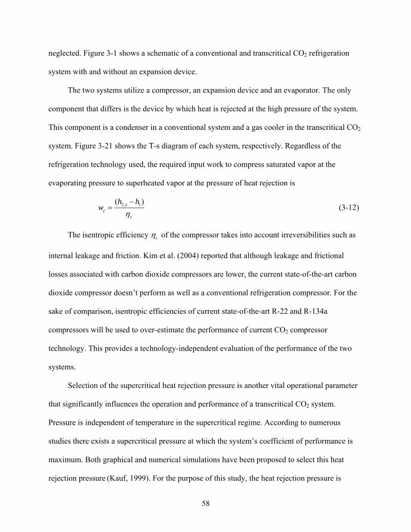
58
neglected. Figure 3-1 shows a schematic of a conventional and transcritical CO2 refrigeration
system with and without an expansion device.
The two systems utilize a compressor, an expansion device and an evaporator. The only
component that differs is the device by which heat is rejected at the high pressure of the system.
This component is a condenser in a conventional system and a gas cooler in the transcritical CO2
system. Figure 3-21 shows the T-s diagram of each system, respectively. Regardless of the
refrigeration technology used, the required input work to compress saturated vapor at the
evaporating pressure to superheated vapor at the pressure of heat rejection is
2, 1( )sc
c
h hw
η−
= (3-12)
The isentropic efficiency cη of the compressor takes into account irreversibilities such as
internal leakage and friction. Kim et al. (2004) reported that although leakage and frictional
losses associated with carbon dioxide compressors are lower, the current state-of-the-art carbon
dioxide compressor doesn’t perform as well as a conventional refrigeration compressor. For the
sake of comparison, isentropic efficiencies of current state-of-the-art R-22 and R-134a
compressors will be used to over-estimate the performance of current CO2 compressor
technology. This provides a technology-independent evaluation of the performance of the two
systems.
Selection of the supercritical heat rejection pressure is another vital operational parameter
that significantly influences the operation and performance of a transcritical CO2 system.
Pressure is independent of temperature in the supercritical regime. According to numerous
studies there exists a supercritical pressure at which the system’s coefficient of performance is
maximum. Both graphical and numerical simulations have been proposed to select this heat
rejection pressure (Kauf, 1999). For the purpose of this study, the heat rejection pressure is
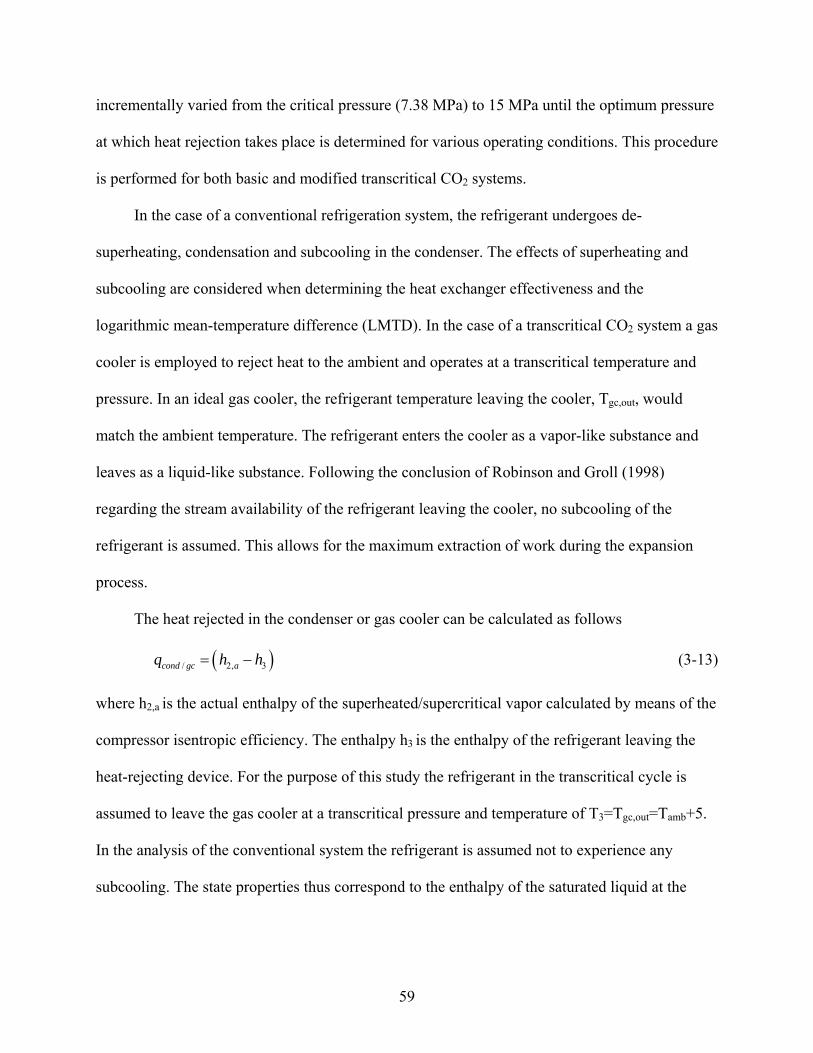
59
incrementally varied from the critical pressure (7.38 MPa) to 15 MPa until the optimum pressure
at which heat rejection takes place is determined for various operating conditions. This procedure
is performed for both basic and modified transcritical CO2 systems.
In the case of a conventional refrigeration system, the refrigerant undergoes de-
superheating, condensation and subcooling in the condenser. The effects of superheating and
subcooling are considered when determining the heat exchanger effectiveness and the
logarithmic mean-temperature difference (LMTD). In the case of a transcritical CO2 system a gas
cooler is employed to reject heat to the ambient and operates at a transcritical temperature and
pressure. In an ideal gas cooler, the refrigerant temperature leaving the cooler, Tgc,out, would
match the ambient temperature. The refrigerant enters the cooler as a vapor-like substance and
leaves as a liquid-like substance. Following the conclusion of Robinson and Groll (1998)
regarding the stream availability of the refrigerant leaving the cooler, no subcooling of the
refrigerant is assumed. This allows for the maximum extraction of work during the expansion
process.
The heat rejected in the condenser or gas cooler can be calculated as follows
( )/ 2, 3cond gc aq h h= − (3-13)
where h2,a is the actual enthalpy of the superheated/supercritical vapor calculated by means of the
compressor isentropic efficiency. The enthalpy h3 is the enthalpy of the refrigerant leaving the
heat-rejecting device. For the purpose of this study the refrigerant in the transcritical cycle is
assumed to leave the gas cooler at a transcritical pressure and temperature of T3=Tgc,out=Tamb+5.
In the analysis of the conventional system the refrigerant is assumed not to experience any
subcooling. The state properties thus correspond to the enthalpy of the saturated liquid at the

60
condenser saturation pressure. In this study the difference between the ambient temperature and
the condensing temperature in the conventional system is assumed to be 15oC.
In conventional and transcritical CO2 refrigeration systems a throttling/expansion valve is
utilized to expand the refrigerant from the pressure of heat rejection to the evaporating pressure.
This irreversible isenthalpic process may be replaced by the use of an expansion device that
would ideally expand the refrigerant in an isentropic fashion. The potential increase in the
system COP due to both the increase in the refrigerating effect and decrease in the cycle net
work input have been studied extensively in recently published literature for systems that utilize
conventional refrigerants and transcritical CO2 as working fluids. Different positive displacement
type expansion devices such as helical-screw, scroll, rotary-vane and reciprocating piston have
been investigated.
In this analysis, the type of expansion device used is not specified. The type of device
along with the geometrical and operational characteristics may be programmed in separate
subroutines that may provide actual performance predictions and an accurate estimate of the
expander’s isentropic efficiency. Depending on the inlet conditions to the expander the actual
work output from the expander can be expressed as
4,
'3( )
ae ew h hη= − (3-14)
The use of expander work output can either be coupled to the compressor shaft or utilized
to drive other auxiliary machinery or systems that may contribute other system improvements.
This study considers only the alternative of increased cooling capacity brought on from near
isentropic expansion and ideal coupling of the expander work to the compressor.
The size of an expansion device is primarily a function of the built-in volume ratio of the
expander. The expander should not only match (or be fairly similar to) the process expansion

61
ratio for typical system operating conditions but should also minimize the amount of wasted
power recovery due to pressure losses incurred during under-expansion. The process volume
ratio is defined as the ratio of the specific volume of the refrigerant at the inlet of the evaporator
to the specific volume at the outlet of the condenser/gas cooler. The expansion process in
positive displacement expansion devices is comprised of the intake, expansion and the exhaust
processes. The built-in volume ratio of an expander is defined as the ratio of the specific volume
at the start of the exhaust process to the specific volume at the end of the intake process. In this
study it is assumed that both the built-in and process volume ratios are identical and defined as
follows
,
3
evap inv
vr
v= (3-15)
where vevap,in is the specific volume of the refrigerant after the expansion process (or at the inlet
to the evaporator). Depending on the cycle analyzed, this state may correspond to an isenthalpic
or non-isentropic expansion process.
We will further assume that the degree of superheat the refrigerant experiences in the
evaporator is assumed to be zero unless otherwise indicated. For a given set of operating
conditions the degree of superheat has much more of an influence on the overall performance of
the system. The refrigerant is thus assumed to be saturated vapor upon exiting the evaporator
unless otherwise indicated. An energy balance of the evaporator yields
4,
'1( )
aevapq h h= − (3-16)
where h’4,a is the actual enthalpy of the refrigerant entering the evaporator determined by means
of the isentropic efficiency of the expander. In the case of an unmodified cycle h’4,a would be
replaced by h4h=h3.

62
The coefficient of performance is defined as a ratio of the desired output to the required
input. In the case of a modified vapor compression system with an expansion device, the net
work input (compressor work less expander work) is the required input to the system. For
simplicity, the work extracted from the expander is assumed to be ideally coupled to the
compressor. The COP is thus defined as
ec
evap
wwq
COP−
= (3-17)
A second-law based comparison of conventional and transcritical CO2 refrigeration
systems is a far better comparison criterion. Exergy or availability analyses reveal how closely
actual refrigeration cycles are to ideal cycles. An exergy analysis also reveals the largest source
of irreversibilities in the system by singling out those components that are most irreversible. The
availability of a flowing fluid stream neglecting both kinetic and potential energy is defined as
( ) ( )0 0 0h h T s sψ = − − − (3-18)
The subscript 0 denotes a reference state at which the system’s temperature and pressure are in
equilibrium with its surroundings (T0=303.15 K ). This state is said to have zero availability if all
other energy forms relative to the surroundings are zero. The specific irreversibility of a steady-
flow device with heat transfer may be expressed as the difference between the reversible work
and the actual work as follows
( ) 01rev act in exit r actr
TI w w q wT
ψ ψ⎛ ⎞
= − = − − − −⎜ ⎟⎝ ⎠
∑ ∑ (3-19)
where qr and Tr are the specific heat transfer and the reservoir temperature at which heat is
transferred to/from, respectively. The sign of qr depends on the direction of heat transfer.
Utilizing Equations (3-18) and (3-19), the specific irreversibilities of the various components can
be derived. The specific irreversibility of an adiabatic compressor may be written as follows

63
( ) ( ) ( )1 2, 1 2, 2, 1c a a o aI h h T s sψ ψ= − − − = − (3-20)
In the case of a conventional system, the specific irreversibility of the condenser is
( )2, 3 0 3 2, 3 2,1 ( ) ( )o ocond a cond a a
r r
T TI q T s s h hT T
ψ ψ⎛ ⎞
= − − − = − − −⎜ ⎟⎝ ⎠
(3-21)
whereas, for a gas cooler, Tr in Equation (3-21) is replaced by the ambient temperature, Tamb. If
the ambient temperature is identical to the reference temperature this expression would reduce to
the difference in availability of the entering and leaving streams.
If the expansion process is performed using a throttling/expansion valve the specific
irreversibility of that isenthalpic process is
( )4, 3v o hI T s s= − (3-22)
whereas in the case of utilizing an expansion device, the specific irreversibility is
( ) ( ) ( )' ' 'exp 3 4, 3 4, 0 4, 3a a aI h h T s sψ ψ= − − − = − (3-23)
The specific irreversibility of the evaporator for both systems is
( ) ( )4 1 1 4 4 11 ( )o oevap evap o
r r
T TI q T s s h hT T
ψ ψ⎛ ⎞
= − + − = − + −⎜ ⎟⎝ ⎠
(3-24)
A system’s total irreversibility is the sum of the irreversibilities associated with its four
components. Irreversibilities resulting from pressure drops in the system’s components and
transfer lines have been neglected. Irreversibilities associated with heat transfer in the system’s
piping have also been neglected.
Both first and second-law based evaluations of R-22, R-134a and transcritical CO2
refrigeration technology are critical for selecting appropriate technology suitable for a specific
application. For this purpose, simulation models for basic and modified vapor-compression
refrigeration cycles have been developed.
64
The selection of the optimum heat rejection pressure is necessary to adequately compare
transcritical CO2 systems to conventional systems. Maximum system COP occurs at the gas
cooler’s optimum heat rejection pressure. Figure 3-22 illustrates the variation of the system COP
as a function of the heat rejection pressure for both basic and modified systems at evaporating
temperatures of 268 and 273 K. The COP of the basic system can be seen as a near constant for
heat rejection pressures greater than the optimum heat rejection pressure. This is not the case for
the modified system since higher heat rejection pressures adversely affect the performance of the
expansion device. For an evaporating temperature of 273K, it can be seen that the COP is
maximum when the heat rejection pressure is 10.2 and 9.75 MPa for the basic and modified
systems, respectively. For an evaporating temperature of 268K the optimum heat rejection
pressures were found to be 10.35 and 9.75 MPa for the basic and modified systems, respectively.
The optimum heat rejection pressure can be determined in a similar fashion for different
evaporating temperatures and operating conditions. For all operating conditions investigated, the
optimum heat rejection pressure has been assumed to be 10.2 MPa. Although the actual optimum
heat rejection pressure may vary by as much as 5% over the entire range of evaporating
temperatures investigated, the system COP deviates by as much as 1 and 1.7% for the basic and
modified systems, respectively. For the sake of computational time this deviation may be
assumed negligible.
Irreversibilities associated with the heat rejection and expansion processes are the largest
sources of irreversibility in basic transcritical CO2 systems. Figure 3-23 illustrates the variation
of the percent of cycle irreversibility associated with the heat rejection and expansion processes
as a function of the heat rejection pressure for basic and modified CO2 systems. For these
operating conditions, the compressor and evaporator contribute approximately 16-17 and 5-6%

65
of the basic cycle’s total irreversibility, respectively. The compressor and evaporator contribute
approximately 22-27 and 9-10% of the modified system’s total irreversibility, respectively. It can
also be seen in Figure 3-23 that the throttle valve contributes 40 to 10% more to the system’s
total irreversibility when compared to the gas cooler at heat rejection pressures of 9 and 11.25
MPa, respectively. In contrast, the contribution of irreversibility from the gas cooler is
approximately 2% less and 25% more at heat rejection pressures of 9 and 11.25 MPa,
respectively. The average irreversibilities of the expansion and heat rejection processes are 24%
lower and 12.5% higher when comparing the modified and basic transcritical CO2 systems,
respectively.
Component irreversibilities corresponding to an optimum heat rejection pressure are
unlikely to be minimum. From Figures 3-22 and 3-23 it can be seen that the optimum heat
rejection pressure corresponds to a maximum system coefficient of performance and a median
value of the system irreversibility.
A first-law based analysis of R-22, R-134a and transcritical CO2 systems is required to
evaluate the thermodynamic performance of basic and modified refrigeration systems.
Employing a two-phase expansion device as a throttle valve replacement is the only modification
made to the basic system. This allows for an unbiased comparison of the different refrigeration
technologies.
Figure 3-24 shows the variation of the coefficient of performance of basic and modified R-
22, R-134a and transcritical CO2 systems as a function of the evaporating temperature. It can be
seen that the COP of the cycles investigated increases with increased evaporating temperature.
The values of system COP for the basic and modified R-22 systems are higher than those of R-
134 systems by as much as 6 and 0.6%, respectively. This maximum difference corresponds to
66
an evaporating temperature of –30oC. For the range of evaporating temperatures investigated, it
can be seen that the COP of the basic transcritical CO2 system is lower than that of R-22 by 33-
34% and that of R-134a by 29-34%. On the other hand, the COP of a modified transcritical CO2
system is lower than that of an R-22 system by 17.5-22% and that of an R-134a by 18-21%. The
COP of a modified transcritical CO2 system is still 4.2-9% less than that of a basic R-22 system.
The COP of a modified transcritical CO2 system is 2% higher and identical to that of a basic R-
134a system operating at evaporating temperatures of –30 and –25oC, respectively. At higher
evaporating temperatures, however, the COP of a transcritical CO2 system is as much as 9%
lower than that of a basic R-134a system.
When compared to similar R-22 and R-134a technology, the performance improvements of
a modified transcritical CO2 system, in comparison to the basic system, are greater. Figures 3-25,
3-26 and 3-27, may further support this result. Figure 3-25 shows the difference in COP between
the basic and modified R-22, R-134 and transcritical CO2 systems as a function of the
evaporating temperature, respectively. It can be seen that the difference in COP decreases with
increased evaporating temperature for all three systems. The decrease is not as rapid however for
the transcritical CO2 system. As the evaporating temperature decreases, the modified CO2, R-
134a and R-22 systems outperform the basic systems by 27-30%, 10-23% and 9-18%,
respectively. This increase in the COP can be attributed to an increase in the refrigerating effect
and a decrease in the input work required to operate the system.
The refrigerating effect is defined as the specific evaporator capacity. From Figure 3-26, it
can be seen that as the evaporating temperature decreases, the differences in the refrigerating
effect of the modified and basic systems increase from 5-14%, 1.2-7% and 1.3-9% for the CO2,
R134a and R-22 systems, respectively. From Figure 3-27, the decrease of the required input to

67
the system can be seen to be dramatically different. The work extracted from the expansion
process is ideally utilized in the reduction of the input work to the compressor. It can be seen that
as the evaporating temperature increases, the difference in required input work to operate a
transcritical CO2 system increases. For increasing evaporating temperatures, the reduction in
input work can be seen to be 22-31%, 14.5-9% and 18.5-10% for transcritical CO2, R-22 and R-
134a systems, respectively. When comparing the basic and modified systems, the sizable
differences in the increase in refrigerating effect and reduction of input work of CO2 point to
favorable thermodynamic characteristics of CO2 when compared to those of R-22 and R-134a.
When dealing with modified systems, the most favorable operational characteristic of CO2
is the volume ratio of the expander. This operational variable discussed earlier determines the
size and practical feasibility of employing a two-phase expansion device as a throttle valve
replacement. Figure 3-28 shows the variation of the expansion device’s volume ratio as a
function of the evaporating temperature for CO2, R-22 and R-134a. As can be seen, there is a
sizable difference between the volume ratios for the different working fluids. It can also be seen
that the volume ratio decreases as the evaporating temperature increases since the specific
volume at the evaporator inlet decreases as temperature increases. For the evaporating
temperatures reported (5 to 20oC only), the volume ratio can be seen to decrease from 2.7-1.6,
12.3-6.2, and 20.8-10 for transcritical CO2, R-22, and R-134a cycles, respectively.
Efficient expansion devices are necessary to justify the cost and performance improvement
of modified refrigeration systems when compared to conventional technology. This result is
evident in Figure 3-29, which shows the difference in COP of basic and modified CO2, R-22 and
R-134a systems as a function of the expander’s isentropic efficiency. In the case of CO2, it can
be seen that the improvement in the system COP increases in a much more dramatic fashion

68
when compared to R-22 and R-134a systems. The increase in the system COP can be seen to be
10.5-33%, 6-19% and 5-17% for CO2, R-134a and R-22 systems, respectively.
A second-law based analysis is needed to determine the irreversibilities of the various
components and to determine the increases/reductions in irreversibilities associated with any
system modification. Figure 3-30 illustrates the component irreversibilities of a modified R-22
system as a function of the evaporating temperature. As can be seen, for the modified R-22
system, the largest sources of irreversibility are the condenser and compressor. Employing an
expansion device has greatly reduced the irreversibilities associated with the basic system’s
throttling process. Component irreversibilities for the basic and modified CO2, R-134a and R-22
systems at a specific operating condition are given in Table 3-2. The table shows that the
irreversibilities associated with the throttling process are reduced by 50, 18 and 16.5% for
modified CO2, R-134a and R-22 systems, respectively. Similar figures and tables may be
generated for various operating conditions and system configurations.
Figure 3-31 shows the percentage of system irreversibility due to the condensing process
for basic and modified R-22 and R-134a systems as functions of the evaporating temperature.
The percentage of system irreversibility associated with the gas cooler for both the basic and
modified transcritical CO2 systems are not included for clarity. It was found that the gas cooler’s
contribution to the system irreversibility is fairly constant and averages 29.5 and 42% for the
basic and modified transcritical CO2 systems, respectively. The figure also shows that the
percentage of the total system irreversibility associated with the condensing process increases
with evaporating temperature and with the use of an expansion device for both R-22 and R-134a
systems. This increase in irreversibility decreases with increased evaporating temperatures from
10-6% and 11-6% for R-134a and R-22 systems, respectively.
69
Figure 3-32 shows the percentage of system irreversibility associated with the expansion
process for basic and modified CO2, R-134a and R-22 systems. As can be seen, the percentage
irreversibility due to expansion is on average 47.5 and 24% for the basic and modified
transcritical CO2 systems, respectively. An average value of 50% reduction in irreversible losses
due to the addition of an expansion device is expected with increasing evaporating temperatures.
Irreversibilities associated with the expansion process in R-134a and R-22 systems decrease with
increased evaporating temperature and may be reduced from 24-11% and 22-10.5%,
respectively.
The ratio of the total system irreversibility to the heat rejection rate yields a dimensionless
system irreversibility that may be used to evaluate and compare the total system irreversibilities
of transcritical CO2, R-22 and R-134a systems. The heat rejection rate has been used to non-
dimensionalize the total system irreversibility since the only difference between conventional
and transcritical refrigeration technology is the heat rejection device. Figure 3-33 shows the
variation of this dimensionless quantity as a function of evaporating temperature for basic and
modified CO2, R-22 and R-134a systems. As can be seen, the basic and modified transcritical
CO2 systems have the largest dimensionless cycle irreversibilities associated with them.
Modified R-22 and R-134a systems, on the other hand, have the least. The basic CO2 system and
the basic R-22 and R-134a systems have fairly close dimensionless cycle irreversibilities.
Theoretical simulation models have been developed to analyze and evaluate the first and
second-law based performance of basic and modified R-22, R-134a and transcritical CO2 vapor
compression refrigeration systems. The use of a two-phase expansion device as a throttle valve
replacement is the only modification made to the basic system. This allows for an unbiased
comparison of the different refrigeration technologies. The following conclusions can be made:

70
• The optimum heat rejection pressure corresponds to a maximum system coefficient of performance and a median value of system irreversibility. For the operating conditions investigated, the optimum heat rejection pressure of a modified system is on average 5% lower than that corresponding to a basic transcritical CO2 system.
• The COP of basic and modified transcritical CO2 technology is inferior when compared to basic and modified R-22 and R-134a systems. The COP of basic and modified transcritical CO2 systems are 29 to 34% and 17.5 to 22% lower than R-22 and R-134a systems, respectively.
• Modified transcritical CO2 systems can compete with basic R-22 and R-134a technology at lower evaporating temperatures but perform about 9% less at higher temperatures.
• Favorable thermodynamic characteristics of CO2 are apparent when comparing the relative increases in COP and refrigerating effect and the reduction in input work to R-22 and R-134a. For the range of evaporating temperatures investigated, the improvement in the CO2 system COP is 12 to 18% when compared to R-22 and R-134a systems. An increase of 3.8 to 7% in refrigerating effect and a 7.5 to 22% decrease in input work were also realized when compared to R-22 and R-134a systems.
• The most favorable operational characteristic of CO2 is the volume ratio of the expander needed to expand the refrigerant to the evaporating pressure. At an evaporating temperature of 5oC the volume ratio of an R-22 and R-134a expander are 4.5 and 7.7 times that of a CO2 expander, respectively.
• Efficient expansion devices are necessary to justify the cost and performance improvement of modified refrigeration systems when compared to conventional technology. When compared to inefficient expansion devices (ηexp=25%), efficient expansion devices (ηexp=85%) may increase the system COP by 33%, 19% and 17% for CO2, R-134a and R-22 systems, respectively.
• The throttling process is the largest source of irreversibility in basic transcritical CO2 systems and the second largest in basic R-22 and R-134a systems. Irreversibilities may be reduced by as much as 50, 24 and 22% for modified CO2, R-134a and R-22 systems, respectively, employing a 65% efficient expansion device.
• The basic and modified transcritical CO2 systems have the largest total irreversibilities associated with them when compared to R-22 and R-134a systems.
Performance and Size Optimization of Compression Refrigeration Systems
A parametric analysis of key system operational variables in a modified vapor compression
refrigeration system is presented in this section. A highly non-linear relationship is found to exist

71
between the many factors that influence the optimization of the system’s coefficient of
performance and the associated size and weight of a refrigeration system.
Of these factors, the degree of subcooling that the refrigerant experiences in the condenser
is the most influential. It is the degree of subcooling that determines the necessary area of the
heat exchanger required, ultimately affecting the size and the weight of a refrigeration system.
The degree of subcooling also influences the size of the expander required to expand the
refrigerant from the condenser pressure to the evaporator pressure. As the degree of subcooling
increases, the resultant ratio between the outlet and inlet specific volumes decreases, and hence
the built-in volume ratio of the expander would decrease. A decrease in the latter causes a
reduction in the expander size and weight.
As the degree of subcooling increases, the useful power output of the expander (which may
be coupled to the compressor) decreases. On the other hand, this causes the enthalpy of the
refrigerant entering the evaporator to decrease. This causes an increase in the refrigerating effect
of the system. The extent of the influence of these competing effects on the system’s coefficient
of performance needed further analysis. This was done using a simulation code developed for
that purpose.
An optimum degree of subcooling exists where the coefficient of performance of the
system is a maximum and the size and weight of the system are a minimum. It is recognized that
the performance and compactness criteria may not be optimized simultaneously by a single
subcooling choice. Furthermore, the penalties associated with the increase of the heat exchanger
area and the decrease of power output of the expander should be minimized, while the benefits of
the increasing refrigerating effect and the decreasing volumetric ratio of the expander should be
maximized.
72
The quantification of the dependencies of the coefficient of performance, size, and weight
of a vapor-compression system on design choices such as the degree of subcooling are now
presented.
Component level models are needed for vapor-compression systems that utilize an
expander in place of the conventional throttling valve. A general solution method may be applied
to model and validate experimental data and/or data provided by the manufacturers. The method
presented is also applicable to both simple and modified vapor compression systems. Detailed
component-level models that may include geometry, flow arrangement and loss mechanisms for
the compressor, condenser, evaporator and expander may be developed separately and
incorporated into this model when required. These component-level models will provide better
estimates of the isentropic efficiencies of both the compressor and expander as well as the heat
exchanger size and effectiveness of the condenser and evaporator. In the analysis described in
this section, R-22 is assumed to be the working fluid. The thermodynamic properties of R-22 are
provided by means of coupling REFPROP 7.0’s property subroutines with the model developed
for this analysis. Pressure losses in all the system components as well as throughout the system’s
piping have been neglected. Figure 3-1 shows a schematic of a simple vapor-compression cycle
with and without an expansion device as a throttle valve replacement.
In general, the required input work to compress saturated vapor at the evaporating pressure
to superheated vapor at the condensing pressure is given by Equation (3-12). The refrigerant
undergoes de-superheating, condensation and subcooling in the condenser. The effects of
superheating and subcooling are considered when determining the heat exchanger effectiveness
and the logarithmic mean-temperature difference (LMTD). As a base case for comparing the
effect of subcooling on system size and performance, the refrigerant leaving the condenser is
73
assumed to be saturated liquid (i.e. no subcooling in the condenser). This represents the
minimum heat exchanger area required to condense the refrigerant to a saturated liquid state and
allow for the completion of the refrigeration cycle. When subcooling is accounted for, the
present analysis only investigates the subcooling that the refrigerant experiences in the condenser
resulting from an increase in the heat exchanger area. Other subcooling methods such as utilizing
a liquid-to-suction heat exchanger or using integrated or mechanically dedicated subcooling
loops are not analyzed in this study.
The heat rejected in the condenser can be calculated as follows
( )3,2 hhq acond −= (3-25)
where h2,a is the actual enthalpy of the superheated vapor calculated by means of the compressor
isentropic efficiency. The enthalpy h3 is the enthalpy of the refrigerant leaving the condenser. In
the base case this corresponds to the enthalpy of the saturated liquid at the condenser saturation
pressure. In cases of subcooling this corresponds to the enthalpy of the subcooled refrigerant
determined at the saturation pressure of the constant-temperature condensing process and the
temperature of the subcooled refrigerant.
The effectiveness of the condenser is generally a function of the heat exchanger geometry,
construction material and surface area. The effectiveness of condensers and evaporators however
is independent of flow arrangement since the refrigerant undergoes an isothermal phase change
process. The effectiveness of the condenser is thus defined as
)(
)(
,,min
,,
incincond
incoutcccond TTC
TTC−
−=&
&ε (3-26)
In the case of a condenser, the refrigerant typically has a very high heat capacity because it
is undergoing phase change. The coolant, on the other hand, experiences the maximum

74
temperature difference and therefore its heat capacity is equal to the minimum heat
capacity, min cC C=& & . In this case, the temperature of the coolant leaving the condenser, Tc,out, can
be calculated as follows
)( ,,,, incincondcondincoutc TTTT −+= ε (3-27)
The relative size of the heat exchanger is calculated from the following Equation
( )cond lmcondQ UA T= Δ& (3-28)
where ΔTlm is the logarithmic mean temperature difference, which is defined as follows
⎟⎟⎠
⎞⎜⎜⎝
⎛
−−
−−−=Δ
outcincond
incoutcond
outcincondincoutcondlm
TTTT
TTTTT
,,
,,
,,,,
ln
)()( (3-29)
Equation (3-29) is applicable to any heat exchanger flow arrangement since the refrigerant
undergoes a phase change process (i.e. correction factor F=1) (Incorpera 2002).
In typical vapor compression refrigeration systems a throttling/expansion valve is utilized
to expand the refrigerant from the condensing pressure to the evaporating pressure. This
irreversible isenthalpic process may be replaced by the use of an expansion device that would
ideally expand the refrigerant in an isentropic fashion. The potential increase in the system COP
due to both the increase in the refrigerating effect and decrease in the cycle net work input have
been studied extensively in recent literature for systems that utilize conventional refrigerants and
transcritical CO2 as working fluids. Many different positive displacement type expansion devices
such as helical-screw, scroll, rotary-vane and reciprocating piston have been investigated.
Here the type of expansion device used is not specified. The type of device along with the
geometrical and operational characteristics may be programmed in separate subroutines that may

75
provide actual performance predictions and an accurate estimate of the expander’s isentropic
efficiency.
Depending on the degree of subcooling the refrigerant experiences in the condenser, the
inlet conditions to the expander may be determined assuming that subcooling in the condenser
occurs at a constant pressure. The actual work output from the expander can be expressed as
4,
'3( )
se ew h hη= − (3-30)
The size of an expansion device is primarily a function of the built-in volume ratio of the
expander. The expander should not only match (or be fairly similar to) the process expansion
ratio for typical system operating conditions, but should also minimize the amount of wasted
power recovery due to pressure losses incurred during under-expansion. The process volume
ratio is defined as the ratio of the specific volume of the refrigerant at the inlet of the evaporator
to the specific volume at the outlet of the condenser. This volume ratio is expected to be smaller
when the refrigerant leaving the condenser is subcooled. The complete expansion process in
positive displacement expansion devices is comprised of the intake, expansion and the exhaust
processes. The built-in volume ratio of an expander is defined as the ratio of the specific volume
at the start of the exhaust process to the specific volume at the end of the intake process. In this
study it is assumed that both the built-in and process volume ratios are identical and defined as
,
.
evap inv
cond out
vr
v= (3-31)
We will further assume that the degree of superheat the refrigerant experiences in the
evaporator is zero unless otherwise indicated. For a given set of operating conditions, the degree
of superheat has much more of an influence on the overall performance of the system. In this
study, the impact of the degree of subcooling on the expander cycle performance and size is of

76
primary interest. The refrigerant is thus assumed to be saturated vapor upon exiting the
evaporator unless otherwise indicated. An energy balance of the evaporator yields
4,
'1( )
aevapq h h= − (3-32)
where h’4,a is the actual enthalpy of the refrigerant entering the evaporator determined by means
of the isentropic efficiency of the expander. The COP is thus defined as
ec
evap
wwq
COP−
= (3-33)
The results presented here are in terms of dimensionless quantities. This allows the reader
to capture general trends of the analysis without the distraction of system specific calculations.
The dimensionless groups that will be extensively used in the presentation of the results are
defined as follows
Dimensionless COP: refrenceCOP
COPCOP =* (3-34)
Dimensionless expander work output: referencew
ww
exp,
exp*exp = (3-35)
Dimensionless expander volume ratio: referencev
vv r
rr
,
* = (3-36)
Dimensionless condenser capacitance:
referencemUA
mUA
mUA
⎟⎠⎞
⎜⎝⎛
⎟⎠⎞
⎜⎝⎛
=⎟⎠⎞
⎜⎝⎛
&
&&
*
(3-37)
For a vapor-compression system of known refrigerating capacity both the overall heat
transfer coefficient, U, of a condenser with a constant effectiveness and the mass flow-rate of
refrigerant may be assumed constant. The condenser capacitance can thus be considered a direct

77
measure of the heat exchanger area required to reject a given heat load in the system’s condenser
if these two conditions are met.
A constant cooling capacity comparison criterion may also be used to constrain the
analysis presented here. In the constant cooling capacity design scenario, the mass flow-rate of
refrigerant through the system would vary depending on the degree of subcooling which will
ultimately reduce the system component and pipe sizing. The reduction in system size and
weight would be significantly less, however, than that achieved by reducing the heat exchanger
area.
Figure 3-34 shows the variation of dimensionless condenser capacitance, expander volume
ratio, expander work output and system COP as functions of the dimensionless refrigerating
effect. In this case, the refrigerant does not experience any subcooling in the condenser. The
refrigerating effect is defined as the difference in the specific enthalpy of the refrigerant at the
exit and the inlet of the evaporator. For a given condensing temperature, the refrigerating effect
increases as the evaporating temperature increases. The data used to plot Figure 3-34 has been
normalized by the refrigerating effect corresponding to the lowest evaporating temperature
analyzed. It can be seen from Figure 3-34 that as the refrigerating effect increases (for instance
due to an increase in the evaporating temperature) the system COP increases dramatically. This
is due to the fact that as the difference in operating temperatures (or pressures) decrease both the
compressor input work required and expander work output decrease. For the operating
temperatures reported, the compressor work input decreases by 74%, while the expander work
output decreases by 84%. Furthermore, for the same temperature range, an increase in the
refrigerating effect of 7.5% is observed. This results in an increase in system COP of about 75%
when compared to a system operating at the lowest evaporating temperature analyzed (223 K).

78
As the refrigerating effect increases, both the size and work output of the expander decrease. As
mentioned earlier, the expander work output decreases by about 84% whereas the expander
volume ratio decreases by 92%. As the evaporating temperature increases, the benefits of
utilizing an expander as a throttle valve replacement become less significant. The condenser
capacitance increases with the increase in the refrigerating effect. Over the full range of the
refrigerating effect considered, the condenser capacitance can be seen to increase by 27%.
Figure 3-35 shows the variation in the dimensionless expander volume ratio and work
output as functions of the evaporating temperature for different degrees of subcooling in the
condenser. The expander volume ratio and work output decrease with an increase in the
evaporating temperature and the degree of subcooling. At an evaporating temperature of 278 K,
typical in air-conditioning applications, the expander volume ratio is found to be 8% and 16.4%
less than the volume ratio corresponding to the case of no subcooling in the condenser for a
degree of subcooling of 4oC and 8oC, respectively. The expander work output was found to be
15.3% and 29% less than the work output corresponding to the case of no subcooling in the
condenser for a degree of subcooling of 4oC and 8oC, respectively.
Figure 3-36 illustrates the variation in the dimensionless condenser capacitance as a
function of the evaporating temperature for different degrees of subcooling in the condenser. It
can be observed that as the degree of subcooling increases, the variation in the condenser
capacitance increases dramatically. For a typical air-conditioning evaporating temperature of 273
K the condenser capacitance is found to be 24.6% and 54.3% greater than that corresponding to
the case of no subcooling in the condenser for a degree of subcooling of 4oC and 8oC,
respectively. As previously mentioned, there exists a direct correlation between the heat
exchanger area and the condenser capacitance. The increase in the heat exchanger area appears
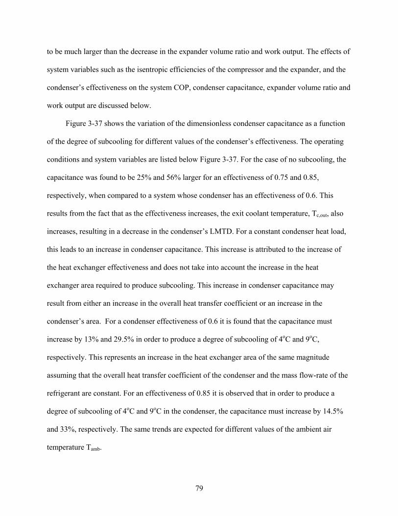
79
to be much larger than the decrease in the expander volume ratio and work output. The effects of
system variables such as the isentropic efficiencies of the compressor and the expander, and the
condenser’s effectiveness on the system COP, condenser capacitance, expander volume ratio and
work output are discussed below.
Figure 3-37 shows the variation of the dimensionless condenser capacitance as a function
of the degree of subcooling for different values of the condenser’s effectiveness. The operating
conditions and system variables are listed below Figure 3-37. For the case of no subcooling, the
capacitance was found to be 25% and 56% larger for an effectiveness of 0.75 and 0.85,
respectively, when compared to a system whose condenser has an effectiveness of 0.6. This
results from the fact that as the effectiveness increases, the exit coolant temperature, Tc,out, also
increases, resulting in a decrease in the condenser’s LMTD. For a constant condenser heat load,
this leads to an increase in condenser capacitance. This increase is attributed to the increase of
the heat exchanger effectiveness and does not take into account the increase in the heat
exchanger area required to produce subcooling. This increase in condenser capacitance may
result from either an increase in the overall heat transfer coefficient or an increase in the
condenser’s area. For a condenser effectiveness of 0.6 it is found that the capacitance must
increase by 13% and 29.5% in order to produce a degree of subcooling of 4oC and 9oC,
respectively. This represents an increase in the heat exchanger area of the same magnitude
assuming that the overall heat transfer coefficient of the condenser and the mass flow-rate of the
refrigerant are constant. For an effectiveness of 0.85 it is observed that in order to produce a
degree of subcooling of 4oC and 9oC in the condenser, the capacitance must increase by 14.5%
and 33%, respectively. The same trends are expected for different values of the ambient air
temperature Tamb.

80
Figure 3-38 shows the variation of the dimensionless expander work output as a function
of the degree of subcooling in the condenser for different isentropic efficiencies of the expander.
Detailed component level models of an expander would incorporate effects of friction and
internal leakage losses and provide an accurate prediction of the expander’s isentropic efficiency.
As it can be seen, the work output from the expander decreases with both the decrease in
isentropic efficiency and increase of the degree of subcooling. For an ideal expander utilized as a
throttle valve replacement it can be shown that a degree of subcooling of 5oC and 10oC results in
a decrease of the work output of the expander by 19% and 35%, respectively, when compared to
the case of no subcooling in the condenser. Expanders whose isentropic efficiencies are 60% and
80% will theoretically produce less work than an ideal expander by that exact amount. An
increase in the degree of subcooling in either case results in a decrease in the expander work
output by 19% and 35% for a degree of subcooling of 5oC and 10oC, respectively. From this
figure it can be concluded that in order to make the use of an expander as a throttle valve
replacement beneficial, losses that affect the expander’s isentropic efficiency as well as the
degree of subcooling the refrigerant experiences in the condenser must be minimized.
Figure 3-39 shows the variation of the expander volume ratio as a function of the degree of
subcooling for different isentropic efficiencies of the expander. The expander volume ratio is
found to increase as the isentropic efficiency of the expander decreases. Not only does the work
output of the expander decrease, but also a larger expander adds both a weight and size penalty
to the modified vapor-compression system. For the case of an ideal expander, a degree of
subcooling of 5oC and 10oC results in an increase in the volume ratio by 10% and 20%,
respectively. When compared to an ideal expander, there exists a 1.67% and 3.33% increase in
the volume ratio for the case of no subcooling in the condenser for expander isentropic

81
efficiencies of 0.8 and 0.6, respectively. For a degree of subcooling of 10oC, this difference can
be shown to decrease to about a 1.4% and 2.8% increase in the expander volume ratio for
isentropic efficiencies of 0.8 and 0.6, respectively, when compared to an ideal expander. It is
observed that the decrease in the expander work output is much more significant when compared
to the increase in the expander volume ratio for both a decrease in the isentropic efficiency of the
expander and the increase in the degree of subcooling the refrigerant experiences in the
condenser.
Figure 3-40 illustrates the variation of a system’s dimensionless COP as a function of the
degree of subcooling for different isentropic efficiencies of the expander. It is observed that as
the degree of subcooling increases, the COP also increases by 2%, 3.4% and 4.7%. This is the
case for 10oC of subcooling in the condenser for expander isentropic efficiencies of unity, 0.8
and 0.6, respectively when compared to the case of no subcooling. For the latter case, the COP is
found to be 1.7% and 3.4% lower than that corresponding to an ideal expander for expander
isentropic efficiencies of 0.8 and 0.6, respectively. It may thus be concluded that the variation in
COP is significant for larger values of subcooling in the condenser and then becomes more
significant as the isentropic efficiency decreases.
Figure 3-41 shows the variation of the dimensionless COP as a function of the degree of
subcooling for different degrees of superheat in the evaporator. The system parameters are
assumed constant and are listed below the figure. Superheating is beneficial to prevent
compressor slugging. An increase in the degree of superheating is generally associated with an
increase in the refrigerating effect and an increase in the input compressor work required to
compress the superheated vapor to the condensing pressure. It is observed that as the degree of
subcooling increases, the COP increases for all values of superheating analyzed. It is also noted

82
that as the degree of superheat increases the COP is seen to decrease. This may be associated
with a significant increase in the compressor input work in contrast to gains in the refrigerating
effect. For the case of no subcooling in the condenser it may be shown that as the degree of
superheat increases, the compressor input work increases by 2.8% and 5.3% whereas the
refrigerating effect increases by 2.4% and 15.8% for a degree of superheat of 5oC and 10oC,
respectively. The degree of superheat has no direct impact on the performance or size of either
the condenser or expander. The degree of superheat should be selected and minimized in order to
maximize a given COP.
The analysis presented in this section provides a foundation for application-specific
optimization. The degree of subcooling the refrigerant experiences in a system’s condenser has a
significant effect on the size and performance of a vapor-compression system utilizing two-phase
expanders as throttle valve replacements. The findings of this analysis are as follows
• As the evaporating temperature increases the benefits of utilizing an expander as a throttle valve replacement become less significant. This can be attributed to significant decreases in the expander volume ratio and work output.
• The expander volume ratio and work output also decrease with increased condenser subcooling.
• The work output from the expander decreases with both the decrease in isentropic efficiency and the increase of the degree of subcooling. Losses that affect an expander’s isentropic efficiency as well as the degree of subcooling must be minimized.
• The decrease in the expander work output is much more significant when compared to the increase in the expander volume ratio for both a decrease in the isentropic efficiency of the expander and the increase in the degree of subcooling.
• The variation in system COP is significant for larger values of subcooling in the condenser and become more significant as the expander’s isentropic efficiency decreases.
• The degree of superheat in the evaporator has no direct impact on the performance or size of either the condenser or expander. The degree of superheat should be selected and minimized in order to maximize a given system’s COP.

83
Pure Hydrocarbons as Refrigerants
Hydrocarbons are very lucrative as refrigerant replacements for CFCs, HCFCs and HFCs
since they are abundant, inexpensive and environmentally friendly because they have no ozone
depletion potential. Among the major drawbacks of using hydrocarbons as refrigerants is their
high flammability potential. This limits their use to hermetic systems and the slightest leak of a
hydrocarbon refrigerant may prove to be catastrophic. The following is a review of recent
literature pertaining to the use of hydrocarbons as pure refrigerants, in mixtures, and issues
pertaining to flammability. The most promising potential hydrocarbons used as refrigerant
substitutes are listed in the Table 3-3 along with pertinent fluid information.
Many researchers have investigated the performance of pure hydrocarbons and
hydrocarbon mixtures as refrigerants. According to Granryd (2001) several standards allow the
use of hydrocarbons as refrigerants in internally safe, hermetically sealed systems with a charge
limit of 0.15 kg. This limits the use of hydrocarbons to domestic refrigerators and freezers and
low capacity heat pumps. Larger refrigeration systems may utilize hydrocarbons as refrigerants
as long as there is adequate exhaust and extreme safety precautions are in place. According to
Granryd (2001) hydrocarbons are compatible with conventional materials used to construct
vapor-compression refrigerating systems.
Granryd (2001) theoretically investigated various cycle and heat transfer characteristics for
various hydrocarbon refrigerants including propane, butane, isobutene, propene (propylene),
cyclopropane, Dimethyl ether and a 50% propane-50% isobutane mixture. The results were
compared with cycle and heat transfer characteristics of R-12, R-22 and R-134a. The author
found that the pressure ratios associated with butane and isobutene are higher while propane and
cyclopropane are lower than that of R-22, respectively. The author also notes that in the case of
using butane and isobutane as refrigerants, a necessary degree of superheat is required at the

84
evaporator exit to ensure that isentropic compression doesn’t move the vapor into the two-phase
region. When comparing the cycle coefficient of performance to the Carnot efficiency, butane
was found to have the highest cycle Carnot efficiency. Granryd (2001) also experimentally
investigated the use of propane in a refrigeration unit and compared its cycle performance with
that of R-12, R-22, R-134a and R-152a. He concluded that a 3-5% increase in system COP and a
3-15% decrease in refrigerating capacity exists when propane is compared to conventional
refrigerants. He attributed the decrease in compressor work to the lower molecular weight of
propane.
The use of pure hydrocarbons and mixtures as refrigerants in domestic refrigerators has
been investigated by Hammad and Alsaad (1999), Jung et al. (2000), Tashtoush et al. (2002),
Sekhar (2004) and Wongwises and Chimres (2005).
Purkayastha and Bansal (1998) presented an experimental study of utilizing propane and a
LPG mix (by mass fraction: 98.95% propane, 1.007% ethane and 0.0397% isobutane) as a
suitable replacement for R-22 in a heat pump. They found an increase in system coefficient of
performance of 18 and 12%, and 9 and 4% for propane and LPG, respectively. These values
correspond to condensing temperatures of 35oC and 55oC, respectively, at an evaporating
temperature of 3oC.
Colbourne and Suen (2004a, 2004b) appraised the flammability hazards of hydrocarbon
refrigerants in refrigeration and heat pump systems. Dlugogorski et al. (2002) experimentally
investigated the use of inerting agents with natural gas and a propane-butane mixture. Their
recommendations however have not been tested experimentally in a refrigeration unit.
In the case of pure hydrocarbon refrigerants the parameters under investigation include the
system coefficient of performance, refrigerating effect, work consumption by the compressor and

85
the effect of both subcooling and superheat on system performance. The case where an expander
is utilized as a throttle valve replacement was also investigated. Comparisons with R-12, R-22
and R-134a were also made to compare the performance of pure hydrocarbons as refrigerants in
both the conventional and modified cycles. The results from these simulations are presented in
Figures 3-42 to 3-47.

86
Figure 3-1. A schematic of the ideal base cycle (1-2-3-4-1) and the modified base cycle with an expansion device (1-2-3-4’-1)
wcomp
qout
1
2
3
4 4’ Te,Pe
Tc,Pc
qin
wexp
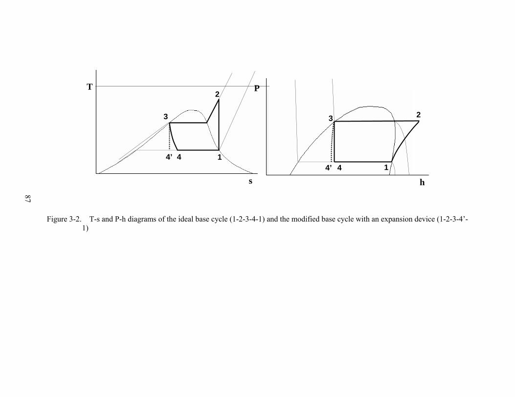
87
Figure 3-2. T-s and P-h diagrams of the ideal base cycle (1-2-3-4-1) and the modified base cycle with an expansion device (1-2-3-4’-1)
s
T
1
2
3
4’ 4
P
h
1
23
4’ 4

88
Figure 3-3. T-s and P-h diagrams of the economizer cycle (1-2-3-4-5-6-7-1) and an economizer cycle with an expansion device as a throttle valve replacement (1-2-3-4-5-6’-7’-1)
Pe
s
T Pc Pi
1
2
3
4
54
6 6’ 6f5
7 7’
h
P
Te Ti
3
4
Tc
1
5
6’ 6f
77’
2

89
Figure 3-4. A schematic of the economizer cycle (1-2-3-4-5-6-7-1) and an economizer cycle with an expansion device as a throttle valve replacement (1-2-3-4-5-6’-7’-1)
qout
2
5
4
Te,Pe
qin
Tc,Pc
wcomp,1
wcomp,2
1
6
3 6g or 6’g
7 7’
wexp,2
6’
wexp,1
6f or 6’f
Separator x
(1-x)

90
Figure 3-5. A schematic of the IHX cycle (1-2-3-4-5-6-1) and the modified IHX cycle with an expansion device as a throttle valve replacement (1-2-3-4-5’-6-1)
wexp
5 5’ 6
Tc,Pc
wcomp
qout
2 3
Te,Pe
qin
1
4
IHX
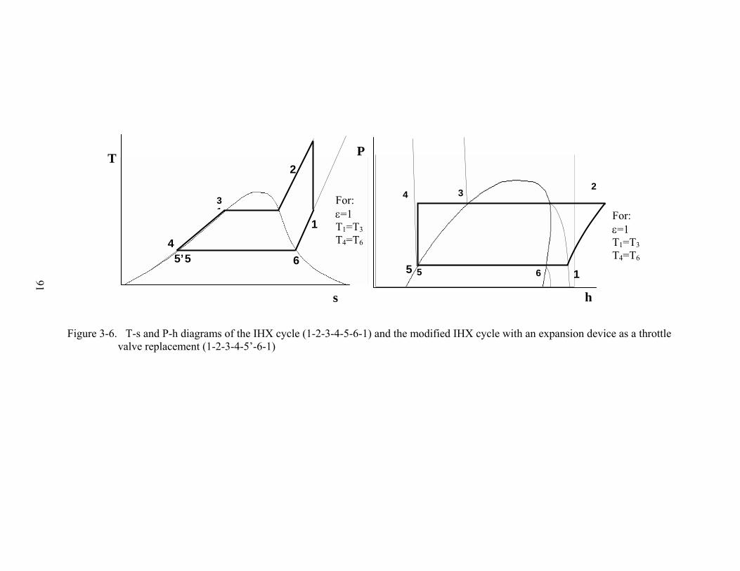
91
Figure 3-6. T-s and P-h diagrams of the IHX cycle (1-2-3-4-5-6-1) and the modified IHX cycle with an expansion device as a throttle
valve replacement (1-2-3-4-5’-6-1)
T
6
2
31
5’5
1
For: ε=1 T1=T3 T4=T6 4
s
P
h
6
23
5 5
For: ε=1 T1=T3 T4=T6
1
4

92
Table 3-1. Summary of the percent changes in the system COP, refrigerating capacity and required work input by the addition of an expansion device for the ideal and actual R-134a single-stage, economizer and IHX cycles
*ηc=85%, ηexp=0.5, εIHX=0.7 ** a decrease in the amount of work needed theoretically *** maximum value corresponds to Te=-20oC and minimum value corresponds to Te=10oC
Ideal*** Actual *,*** Tc, oC Evaporating Range ΔCOP, % ΔQe, % ΔWnet, % ∗∗ ΔCOP, % ΔQe, % ΔWnet, % ∗∗
25 -20oC to 10oC 8-18.7 0.4-3.4 7.6-15.9 3.4-8.3 0.2-1.7 3.3-7.2 30 -20oC to 10oC 10.3-21.4 0.76-4.3 9.6-17.8 4.5-9.6 0.4-2.2 4.3-8.2 35 -20oC to 10oC 12.9-24.2 1.2-5.4 11.9-20 5.6-11 0.6-2.8 5.3-9.2 40 -20oC to 10oC 15.6-27.1 1.8-6.7 14-22 6.8-12.4 0.9-3.5 6.4-10.3
Base Cycle
45 -20oC to 10oC 18.5-30.2 2.4-8.2 16.5-24 8.2-14 1.2-4.3 7.5-11.4 25 -20oC to 10oC 5.2-11 0.3-1.7 4.9-9 2.2-4.8 0.2-1.4 2.1-3.7 30 -20oC to 10oC 6.5-12 0.5-2 6.1-10.2 2.9-5.6 0.4-1.7 2.6-4.1 35 -20oC to 10oC 8.1-14 0.7-2.6 7.4-11.4 3.5-6.4 0.5-2.2 3.2-4.6 40 -20oC to 10oC 9.6-15.5 1-3.2 8.8-12.7 4.3-7.3 0.8-2.7 3.7-5.1
Economizer Cycle
45 -20oC to 10oC 11.4-17.4 1.3-3.9 10.2-14.1 5.1-8.3 1.1-3.3 4.3-5.6 25 -20oC to 10oC 2.6-3.6 0.14-0.6 2.5-3 1.6-2.9 0.1-0.6 1.5-2.4 30 -20oC to 10oC 3-3.9 0.2-0.7 2.8-3.3 1.9-3.3 0.2-0.7 1.8-2.7 35 -20oC to 10oC 3.4-4.5 0.3-1 3.23-3.7 2.3-3.7 0.2-0.9 2.1-2.9 40 -20oC to 10oC 3.9-5 0.4-1.2 3.6-4 2.7-4.2 0.6-1.1 2.4-3.2
IHX Cycle
45 -20oC to 10oC 4.4-5.5 0.6-1.4 4-4.4 3.1-4.7 0.5-1.4 1.7-3.5

93
Figure 3-7. Variation of �COP, between the modified cycle with an expansion device and the ideal cycle (R-134a), with evaporating temperature for A) Tc=25oC, B) Tc=45oC for the base, economizer and IHX cycles
0%
2%
4%
6%
8%
10%
12%
14%
-2 0 2 4 6 8 10
Evaporating Temperature, oC
Incr
ease
in C
OP
Base Tc=25CEconomizer Tc=25CIHX Tc=25C
0%
5%
10%
15%
20%
25%
30%
-2 0 2 4 6 8 10
Evaporating Temperature, oC
Incr
ease
in C
OP
Base Tc=45CEconomizer Tc=45CIHX Tc=45C
A
B

94
Figure 3-8. Variation of ΔQe and ΔWnet, between the ideal modified cycle with an expansion device and an ideal base cycle, with evaporating temperature for various condenser temperatures in a single-stage vapor-compression refrigeration unit (negative denotes a reduction).
-25%
-20%
-15%
-10%
-5%
0%
5%
10%
-2 0 2 4 6 8 10
Evaporating Temperature, oC
Cha
nge
in R
efrig
erat
ing
Effe
ct a
nd N
et W
ork
Tc=25CTc=30CTc=35CTc=40CTc=45C
ΔQe
ΔWnet

95
Figure 3-9. Variation of ΔCOP, between the modified cycle with an expansion device and the ideal cycle, as a function of the evaporating temperature for both R-22 and R-134a for various expander efficiencies Tc=45oC (ηcomp=85% when not ideal)
0
5
10
15
20
25
-2 0 2 4 6 8 10
Evaporating Temperature, oC
ΔCO
P
R-134a, Ideal
R-22, Ideal
ηexp=1
ηexp=0.75
ηexp=0.5

96
Figure 3-10. Variation of ΔCOP, between the modified cycle with an expansion device and the ideal cycle, as a function of the evaporating temperature for various condenser temperatures for the actual and ideal cycle configurations of the economizer cycle.
0%
2%
4%
6%
8%
10%
12%
14%
16%
18%
20%
-20 -15 -10 -5 0 5 10
Evaporating Temperature, oC
Cha
nge
in C
OP
Actual, Tc=25C Actual, Tc=45CIdeal, Tc=25CIdeal, Tc=45C
ηcomp=85%, ηexp=0.5
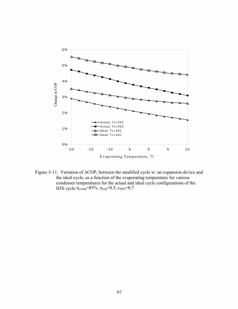
97
Figure 3-11. Variation of ΔCOP, between the modified cycle w/ an expansion device and the ideal cycle, as a function of the evaporating temperature for various condenser temperatures for the actual and ideal cycle configurations of the IHX cycle
0%
1%
2%
3%
4%
5%
6%
-20 -15 -10 -5 0 5 10
E vaporating T em perature, oC
Cha
nge
in C
OP
A ctua l, Tc=25C A c tua l, Tc=45CIdea l, Tc=25CIdea l, Tc=45C
ηcomp=85%, ηexp=0.5, εIHX=0.7

98
Figure 3-12. Variation of refrigerating efficiency as a function of the evaporating
temperature for both the base (no expander) and ideal and actual modified cycle with and an expander at a condenser temperature of Tc=45oC
Figure 3-13. Variation of refrigerating efficiency as a function of the evaporating temperature for the actual base, IHX and economizer cycles with an expander at a condenser temperature of Tc=25oC
0.75
0.8
0.85
0.9
0.95
1
-2 0 2 4 6 8 10
Evaporating Temperature, oC
Ref
riger
atin
g Ef
ficie
ncy
R-134aR-22
ηexp=1
ηexp=0.75
No Expander
ηcomp=85%, ηexp=0.5, εIHX=0.7
0.4
0.5
0.6
0.7
0.8
0.9
-20 -15 -10 -5 0 5 10
Evaporating Temperature, oC
Ref
riger
atin
g Ef
ficie
ncy
Actual, IHX Cycle
Actual, Base Cycle
Actual, Economizer Cycle
oC

99
4
6
8
10
12
14
16
0 2 4 6 8
ΔTsubcooling, oC
CO
P
Tc=25CTc=30CTc=35CTc=40CTc=45C
Figure 3-14. Variation of an ideal system’s COP as a function of the degree of subcooling for various condensing temperatures (Te=5oC, ΔTsh=0 oC)

100
Figure 3-15. Variation of an ideal system’s COP as a function of the degree of subcooling for various condenser temperatures and expansion processes (Te=5oC, ΔTsh=0oC)
0
2
4
6
8
10
12
14
16
0 2 4 6 8 10
ΔTsubcooling, oC
CO
P
Isenthalpic Expansion
Isentropic Expansion
Tc=25oC
Tc=45oC

101
Figure 3-16. Variation of the refrigerating effect as a function of the degree of subcooling for various condenser temperatures and expansion processes (ΔTsh=0oC)
100
120
140
160
180
200
0 2 4 6 8
ΔTsubcooling, oC
Ref
riger
atin
g Ef
fect
, kJ/k
Isenthalpic Expansion
Isentropic Expansion
Tc=45oC
Tc=25oC

102
10
14
18
22
26
30
5 7 9 11 13 15
Evaporator temperature, oC
CO
P
0 C sc, Isenthalpic5 C sc, isenthalpic0 C sc, Isentropic5 C sc, Isentropic
Figure 3-17. Variation in an ideal system’s COP with respect to the evaporator temperature for different degrees of subcooling and expansion processes (ΔTsh=0oC)

103
Figure 3-18. Variation of the difference in system COP,%, between the ideal cycle and modified cycle with an expansion device as a function of the evaporator temperature for various condenser temperatures and degrees of subcooling (ΔTsh=0oC)
0
5
10
15
20
25
5 7 9 11 13 15
Evaporator temperature, oC
ΔC
OP
0C0C5C5C
ΔTsc
Tc=25oC
Tc=45oC

104
0
5
10
15
20
25
0 2 4 6 8
ΔTsuperheat, oC
ΔCO
P
Tc=25CTc=35CTc=45C
Figure 3-19. Variation of the difference of the system COP, %, base cycle and modified cycle with an expansion device as a function of the degree of superheat in the evaporator for various condenser temperatures.

105
100
120
140
160
180
200
0 2 4 6 8ΔTsuperheat, oC
Ref
riger
atin
g Ef
fect
, kJ/
kg
Tc=25CTc=35CTc=45C
Figure 3-20. Variation of the refrigerating effect for an ideal cycle as a function of the degree of superheat for various condenser temperatures
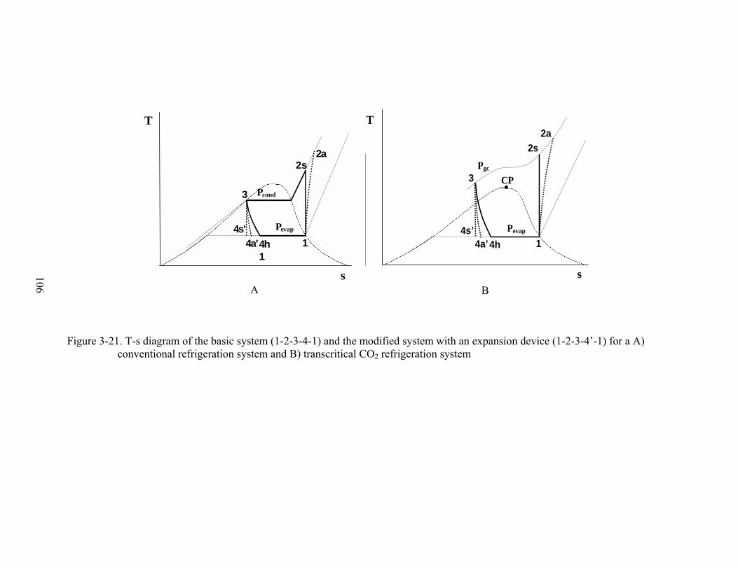
106
Figure 3-21. T-s diagram of the basic system (1-2-3-4-1) and the modified system with an expansion device (1-2-3-4’-1) for a A)
conventional refrigeration system and B) transcritical CO2 refrigeration system
s
T
1
2s
3
4s’ 4a’ 4h
1
2a
Pevap
Pcond
s
T
1
2s
3
4s’4a’4h
2a
Pevap
Pgc
CP
A B

107
Figure 3-22. Variation of system coefficient of performance as a function of heat
rejection pressure for various evaporating temperatures for basic and modified transcritical CO2 systems
Figure 3-23. Percentage of cycle irreversibility associated with the heat rejection and expansion processes as a function of heat rejection pressure for basic and modified transcritical CO2 systems
1.5
2
2.5
3
3.5
9 9.5 10 10.5 11 11.5
Heat Rejection Pressure, MPa
CO
PTe=273 K
Te=268 K
Te=273 K
Te=268 K
Modif ied System
Basic System
0
10
20
30
40
50
60
9 9.5 10 10.5 11 11.5
Heat Rejection Pressure, MPa
Irrev
ersi
bilit
y %
Gas coolerValveGas coolerExpander
ηcomp=0.85
ηexp=0.65T3=313 KTev ap=273 K
Basic SystemModified System

108
Figure 3-24. Coefficient of performance of basic and modified R-22, R-134a and
transcritical CO2 systems as functions of the evaporating temperature
Figure 3-25. Difference in coefficient of performance between basic and modified R-22, R-134a and transcritical CO2 systems as functions of the evaporating temperature
0%
5%
10%
15%
20%
25%
30%
35%
-30 -25 -20 -15 -10 -5 0 5
Evaporating Temperature, oC
ΔC
OP
R-744
R-134a
R-22
ηcomp=0.85ηexp=0.65Tamb=35oCTcond=50oCTgc_out=40oC
1
2
3
4
5
-30 -25 -20 -15 -10 -5 0 5
Evaporating Temperature, oC
CO
PBasic R-744 System
M odified R-744 System
Basic R-134a System
M odified R-134aSystemBasic R-22 System
M odified R-22 System
ηcomp=0.85ηexp=0.65Tamb=35oCTcond=50oCTgc_out=40oC

109
Figure 3-26. Difference in refrigerating effect between basic and modified R-22, R-134a
and transcritical CO2 systems as functions of the evaporating temperature
Figure 3-27. Difference in system input work between basic and modified R-22, R-134a and transcritical CO2 systems as functions of the evaporating temperature (negative denotes a decrease)
0
0.04
0.08
0.12
0.16
-30 -20 -10 0
Evaporating temperature, oC
ΔRe
frig
erat
ing
Effe
ct
R-744R-134aR-22
ηcomp=0.85ηexp=0.65Tamb=35oCTcond=50oCTgc_out=40oC
-30%
-20%
-10%
0%
-30 -20 -10 0
Evaporating Temperature, oC
ΔIn
put W
ork
R-744R-134aR-22
ηcomp=0.85ηexp=0.65Tamb=35oCTcond=50oCTgc_out=40oC
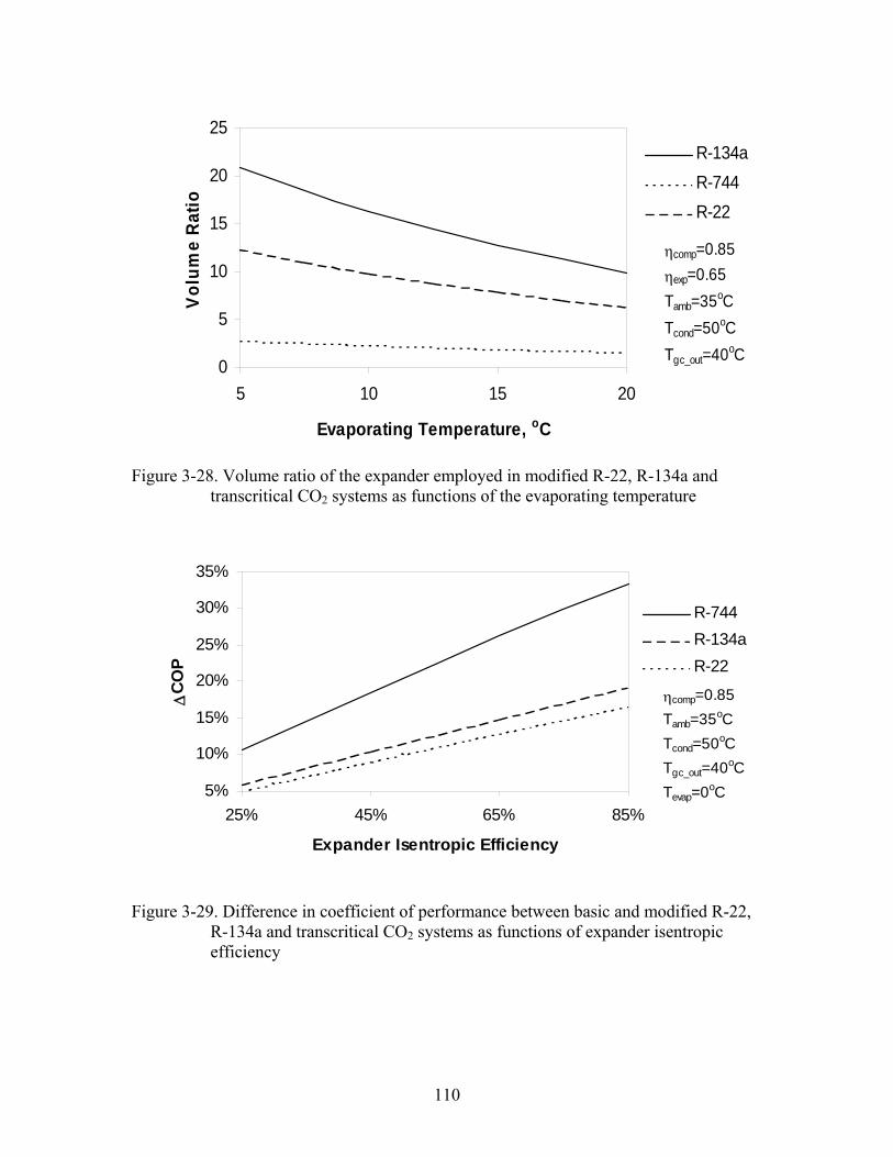
110
Figure 3-28. Volume ratio of the expander employed in modified R-22, R-134a and transcritical CO2 systems as functions of the evaporating temperature
Figure 3-29. Difference in coefficient of performance between basic and modified R-22, R-134a and transcritical CO2 systems as functions of expander isentropic efficiency
0
5
10
15
20
25
5 10 15 20
Evaporating Temperature, oC
Vol
ume
Rat
io
R-134aR-744R-22
ηcomp=0.85ηexp=0.65Tamb=35oCTcond=50oCTgc_out=40oC
5%
10%
15%
20%
25%
30%
35%
25% 45% 65% 85%
Expander Isentropic Efficiency
ΔCO
P
R-744R-134aR-22
ηcomp=0.85Tamb=35oCTcond=50oCTgc_out=40oCTevap=0oC
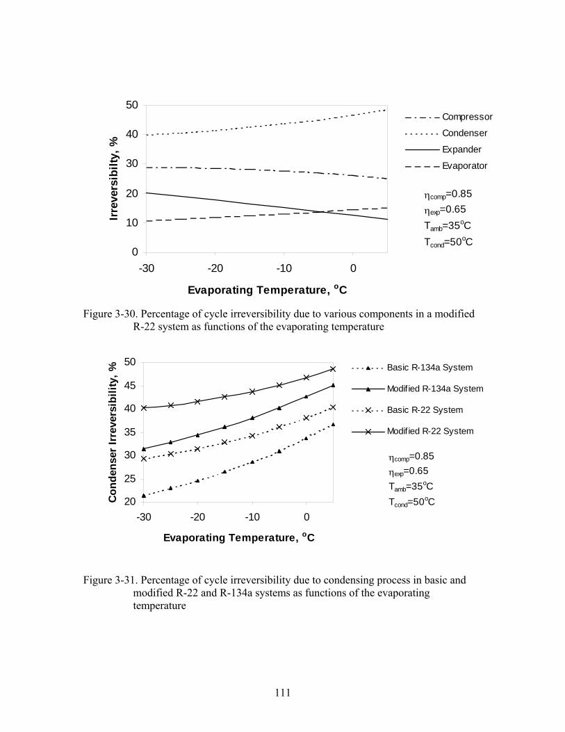
111
Figure 3-30. Percentage of cycle irreversibility due to various components in a modified R-22 system as functions of the evaporating temperature
Figure 3-31. Percentage of cycle irreversibility due to condensing process in basic and
modified R-22 and R-134a systems as functions of the evaporating temperature
0
10
20
30
40
50
-30 -20 -10 0
Evaporating Temperature, oC
Irrev
ersi
bilty
, %Compressor
Condenser
Expander
Evaporator
ηcomp=0.85ηexp=0.65Tamb=35oCTcond=50oC
20
25
30
35
40
45
50
-30 -20 -10 0
Evaporating Temperature, oC
Con
dens
er Ir
reve
rsib
ility
, %
Basic R-134a System
Modif ied R-134a System
Basic R-22 System
Modif ied R-22 System
ηcomp=0.85ηexp=0.65Tamb=35oCTcond=50oC

112
Figure 3-32. Percentage of cycle irreversibility due to the expansion process in basic and
modified R-22, R-134a and transcritical CO2 systems as functions of the evaporating temperature
Figure 3-33. Dimensionless system irreversibility in basic and modified R-22, R-134a and transcritical CO2 systems as functions of the evaporating temperature
0
10
20
30
40
50
60
-30 -20 -10 0
Evaporating Temperature, oC
Expa
nsio
n Pr
oces
s Irr
ever
sibi
lity,
%
Basic R-744 System
M odified R-744 System
Basic R-134a System
M odified R-134a System
Basic R-22 System
M odified R-22 System
ηcomp=0.85ηexp=0.65Tamb=35oCTcond=50oCTgc_out=40oC
0.1
0.15
0.2
0.25
0.3
0.35
-30 -20 -10 0
Evaporating Temperature, oC
Tota
l Irr
ever
sibi
lity/
Heat
Re
ject
ion
Rate
Basic R-744 System
Modified R-744 System
Basic R-134a System
Modified R-134a System
Basic R-22 System
Modified R-22 System
ηcomp=0.85ηexp=0.65Tamb=35oCTcond=50oCTgc_out=40oC
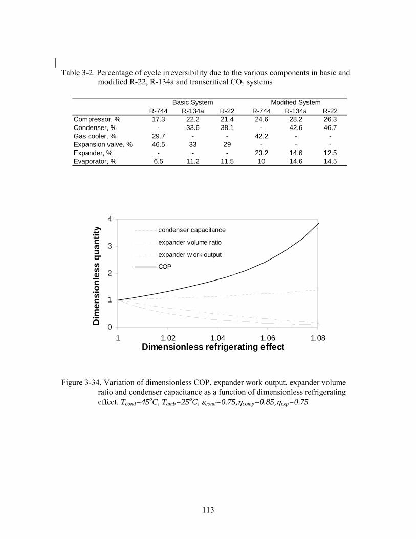
113
0
1
2
3
4
1 1.02 1.04 1.06 1.08Dimensionless refrigerating effect
Dim
ensi
onle
ss q
uant
ity condenser capacitance
expander volume ratio
expander w ork output
COP
Table 3-2. Percentage of cycle irreversibility due to the various components in basic and
modified R-22, R-134a and transcritical CO2 systems
Figure 3-34. Variation of dimensionless COP, expander work output, expander volume
ratio and condenser capacitance as a function of dimensionless refrigerating effect. Tcond=45oC, Tamb=25oC, εcond=0.75,ηcomp=0.85,ηexp=0.75
R-744 R-134a R-22 R-744 R-134a R-22Compressor, % 17.3 22.2 21.4 24.6 28.2 26.3Condenser, % - 33.6 38.1 - 42.6 46.7Gas cooler, % 29.7 - - 42.2 - -Expansion valve, % 46.5 33 29 - - -Expander, % - - - 23.2 14.6 12.5Evaporator, % 6.5 11.2 11.5 10 14.6 14.5
Basic System Modified System

114
Figure 3-35. Variation of dimensionless expander work output and expander volume ratio as a function of evaporating temperature for various degrees of subcooling in the condenser. Tcond=45oC, Tamb=25oC, εcond=0.75,ηcomp=0.85,ηexp=0.75
Figure 3-36. Variation of dimensionless condenser capacitance as a function of evaporating temperature for various degrees of subcooling in the condenser. Tcond=45oC, Tamb=25oC, εcond=0.75,ηcomp=0.85,ηexp=0.75
0
0.2
0.4
0.6
0.8
1
-40 -30 -20 -10 0 10
Evaporating temperature, oC
Dim
ensi
onle
ss w
exp
and
r v048048
Degree of Subcooling, oC
dimensionlessrv
dimensionlessw exp
0
1
2
3
-40 -30 -20 -10 0 10
Evaporating temperature, oC
Dim
ensi
onle
ss c
onde
nser
capa
cita
nce
048
Degree of Subcooling, oC

115
Figure 3-37. Variation of dimensionless condenser capacitance as a function of degree of subcooling in the condenser for various values of condenser effectiveness. Tcond=45oC, Tevap=5oC, Tamb=25oC,ηcomp=0.75,ηexp=0.75
Figure 3-38. Variation of dimensionless expander work output as a function of degree of
subcooling in the condenser for various expander efficiencies. Tcond=45oC, Tevap=5oC, Tamb=30oC, εcond=0.75,ηcomp=0.85
1
1.4
1.8
2.2
2.6
0 2 4 6 8
Degree of subcooling, oC
Dim
ensi
onle
ss c
onde
nser
capa
cita
nce 0.6
0.75
0.85
Condenser effectiveness
0.3
0.5
0.7
0.9
0 2 4 6 8 10
Degree of subcooling, oC
Dim
ensi
onle
ss e
xpan
der
wor
k ou
tput
10.80.6
Expander efficiency

116
Figure 3-39. Variation of dimensionless expander volume ratio as a function of degree of
subcooling in the condenser for various expander efficiencies. Tcond=45oC, Tevap=5oC, Tamb=30oC, εcond=0.75,ηcomp=0.85
Figure 3-40. Variation of dimensionless COP as a function of degree of subcooling in the condenser for various expander efficiencies. Tcond=45oC, Tevap=5oC, Tamb=30oC, εcond=0.75,ηcomp=0.85
0.92
0.96
1
1.04
0 2 4 6 8 10
Degree of subcooling, oC
Dim
ensi
onle
ss C
OP
0.6
0.81
Expander efficiency
0.8
0.85
0.9
0.95
1
1.05
0 2 4 6 8 10
Degree of subcooling, oC
Dim
ensi
onle
ss e
xpan
der
volu
me
ratio
10.80.6
Expander efficiency

117
Figure 3-41. Variation of dimensionless COP as a function of degree of subcooling in the condenser for various evaporator degree of superheat. Tcond=45oC, Tevap=5oC, Tamb=25oC, εcond=0.75,ηcomp=0.85, ηexp=0.85
Table 3-3. Hydrocarbons viewed as potential refrigerants
MW Tcrit,
OC Pcrit, kPa
ρcrit kg/m3
Butane (R600) 58.12 151.98 3796 227.84Ethane (R170) 30.07 32.18 4872 206.58Isobutane (R600a) 58.12 134.67 3640 224.35Propane (R-290) 44.1 96.675 4247 218.5Propene (Propylene) (R1270) 42.08 92.42 4664 223.39
0.98
1
1.02
1.04
0 2 4 6 8 10
Degree of subcooling, oC
Dim
ensi
onle
ss C
OP
1050
Degree of superheat, oC

118
Figure 3-42. Variation of the refrigerating effect as a function of evaporating temperature for various refrigerants at a condensing temperature of A) 25oC and B) 45oC for the ideal base cycle
0
50
100
150
200
250
300
350
400
-5 0 5 10
Evaporating Temperature, oC
Ref
riger
atin
g Ef
fect
, kJ/
kg
0
50
100
150
200
250
300
350
-5 0 5 10
Evaporating Temperature, oC
R-134aR-22R-12ButaneIsobutanePropaneProplyene
A B

119
Figure 3-43. Variation of the ideal base cycle coefficient of performance as a function of evaporating temperature for various refrigerants at a condensing temperature of A) 25oC and B) 45oC
7
9
11
13
15
17
-5 0 5 10
Evaporating Temperature, oC
Coe
ffici
ent o
f Per
form
ance
3
4
5
6
7
-5 0 5 10
Evaporating Temperature, oC
R-134aR-12R-22ButaneIsobutanePropaneProplyene
A B

120
Figure 3-44. Variation of compressor work as a function of the evaporating temperature at a condensing temperature of A) 25oC and B) 45oC for various refrigerants in an ideal base cycle
05
1015202530354045
-5 0 5 10
Evaporating Temperature, oC
Com
pres
sor W
ork,
kJ/
kg
15
25
35
45
55
65
-5 0 5 10
Evaporating Temperature, oC
R-134aR-22R-12ButaneIsobutanePropaneProplyene
A B

121
Figure 3-45. Variation of the increase of COP (when comparing the base cycle and the expander cycle) as a function of the evaporating temperature for various refrigerants at a condensing temperature of A) 25oC and B) 45oC
6%7%8%9%
10%11%12%13%14%15%
-5 0 5 10
Evaporating Temperature, oC
R-134aR-22R-12ButaneIsobutanePropaneProplyene
14%
16%
18%
20%
22%
24%
26%
28%
-5 0 5 10
Evaporating Temperature, oC
Incr
ease
in C
OP
(bas
e cy
cle
and
Expa
nder
cyc
le)
A B

122
Figure 3-46. Variation of the decrease in net-work (when comparing the base cycle and the expander cycle) as a function of the
evaporating temperature for various refrigerants at a condensing temperature of a) 25oC and b) 45oC
5%6%7%8%9%
10%11%12%13%14%
-5 0 5 10
Evaporating Temperature, oC
Dec
reas
e in
the
net w
ork
(bet
wee
n th
e ba
se c
ycle
and
exp
ande
r cyc
le)
10%
12%
14%
16%
18%
20%
22%
24%
-5 0 5 10
Evaporating Temperature, oC
R-134aR-22R-12ButaneIsobutanePropaneProplyene
A B

123
Figure 3-47. Variation of the increase in refrigerating effect (when comparing the base cycle and the expander cycle) as a function of the evaporating temperature for various refrigerants at a condensing temperature of a) 25oC and b) 45oC
0%
1%
2%
3%
4%
5%
6%
-5 0 5 10
Evaporating Temperature, oCIn
crea
se in
the
refr
iger
atin
g ef
fect
(w
hen
com
parin
g ba
se c
ycle
and
ex
pand
er c
ycle
) R-134aR-22R-12ButaneIsobutanePropanePropylene
0.0%
0.3%
0.5%
0.8%
1.0%
1.3%
1.5%
1.8%
-5 0 5 10
Evaporating Temperature, oC
Incr
ease
in th
e re
frig
erat
ing
effe
ct
(whe
n co
mpa
ring
base
cyc
le a
nd
expa
nder
cyc
le)
A B
124
CHAPTER 4 MATHEMATICAL MODEL OF AN IDEAL ROTARY-VANE EXPANDER
Much literature has been reviewed in order to formulate an accurate and rigorous
analytic thermodynamic and fluid model of a rotary-vane expander. Most of the literature
found deals with rotary-vane expanders used predominantly in high-temperature
applications where the working fluid is vapor (namely steam and R-113) and is modeled
using ideal-gas relations. This negates the many additional complexities that arise due to
the necessary formation of vapor from liquid exiting the condenser in vapor compression
cycles. These modeling complexities may include but are not limited to cavitational
erosion, choking, issues dealing with lubrication, and a possible increase of friction and
internal leakage losses due to significant variations in the density and viscosity of the
two-phase working fluid. In order to accurately model a two-phase rotary-vane expander,
the studies conducted in the existing literature must be revisited and modified accordingly
to predict such parameters as the working fluid’s pressure, temperature and mass
variations as well as an overall estimate of power losses, volumetric efficiency, power
output and torque of the rotary-vane expander.
Literature Review of Modeling of Rotary-vane Expanders
While literature dealing with modeling and design improvements of various types
of compressors and expanders, such as helical screw, reciprocating piston, scroll,
Wankel-engines Badr et al. (1991a, 1991b, 1991c) and rotary-piston are abundant, this
review is confined to rotary-vane (or sliding-vane) type expanders and compressors,
hence referred to as MVE and MVC, respectively. Smith et al. (1990, 1992) introduced
the principles, operation and testing of a novel type compressor, the Groll rotary-vane
compressor. They found a 19% and 15% increase in volumetric and adiabatic

125
efficiencies, respectively when compared to a conventional rotary-vane compressor.
There have not been any studies utilizing this as an expansion device.
The positive-displacement rotary-vane expander has been widely used for waste
heat recovery in Rankine cycles. Badr et al. (1984) cited economics, ease of
manufacturing and low maintenance as the most important parameters in the selection of
a MVE as an expansion device. Among the investigators who developed mathematical
models describing the geometry of rotary-vane type turbomachinery (compressors,
expanders, pumps and air-motors) are Wolgemuth and Olson (1971), Marsters and
Ogbuefi (1972), Badr et al. (1985a, 1985b), Somayajulu (1971), and Ben-Bassat and
Wolgemuth (1972). Mechanical friction in a MVE has been investigated by Beck et al.
(1966), Ben-Bassat and Wolgemuth (1972), Peterson and McGahan (1972), Badr et al.
(1986a), Robertson and Wolgemuth (1978), and Edwards and McDonald (1972). Internal
leakage losses in a MVE have been investigated by Peterson and McGahan (1972),
Jacazio et al. (1979), Badr et al. (1985c), and Robertson and Wolgemuth (1978).
All of the above studies either dealt with the expansion or compression of a
working fluid (air, steam, and vapor) that could be modeled by the ideal-gas equation of
state. The studies in question also dealt with rotary-vane type turbomachinery utilized as
expanders in Rankine cycles as air motors or pumps. Table 4-1 summarizes the type of
application, working fluid, analyses performed, and the type of losses accounted for. The
extent and accuracy of their analyses is beyond the scope of this work.
Model Development
In order to accomplish this, five separate subroutines had to be constructed to
accurately predict the aforementioned parameters. A simplified flow diagram of the main

126
computer program that has been developed and a brief description, in subsequent
sections, of the subroutines to be utilized is presented in Figure 4-1.
Thermophysical Model
NIST’s REFPROP 7.0’s refrigerant property subroutines are linked with the
various models and are called whenever thermo-physical data is required. The capability
to both use pure refrigerants and common refrigerant mixtures allows the use of
REFPROP’s property subroutines no matter the refrigerant. There is also the capability
to use of a user defined and customized mixture.
Geometric and Kinematic Model
In order to model the performance of a rotary-vane expander, the geometry of the
expander and kinematics of the vanes must be accurately described mathematically. The
basic geometrical and kinematic characteristics, as a function of the angular displacement
of the expander’s rotor, are required to evaluate the performance of the expander. The
parameters needed include:
• Variation of the cell volumes • Volume expansion ratio, rv=V2/V1 (Figure 4-2) • Variations of the protrusions of the vanes outside their rotor’s slots • Vane’s sliding velocity • Vane’s accelerations
A review of the literature reveals that many different models have been considered
(Table 4-1). A primary difference among the models is accounting for the vane
thickness. Many researchers have assumed an idealized vane thickness of zero when
calculating the cell volume.
For the purpose of this study, the expander is assumed to have a circular stator-
cylinder and the thickness of the vanes is taken into account initially. It can be shown
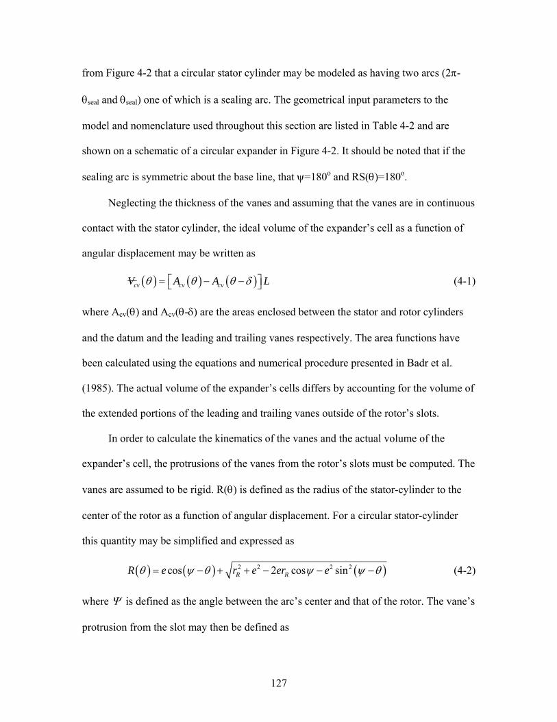
127
from Figure 4-2 that a circular stator cylinder may be modeled as having two arcs (2π-
θseal and θseal) one of which is a sealing arc. The geometrical input parameters to the
model and nomenclature used throughout this section are listed in Table 4-2 and are
shown on a schematic of a circular expander in Figure 4-2. It should be noted that if the
sealing arc is symmetric about the base line, that ψ=180o and RS(θ)=180o.
Neglecting the thickness of the vanes and assuming that the vanes are in continuous
contact with the stator cylinder, the ideal volume of the expander’s cell as a function of
angular displacement may be written as
( ) ( ) ( )cv cv cvV A A Lθ θ θ δ⎡ ⎤= − −⎣ ⎦ (4-1)
where Acv(θ) and Acv(θ-δ) are the areas enclosed between the stator and rotor cylinders
and the datum and the leading and trailing vanes respectively. The area functions have
been calculated using the equations and numerical procedure presented in Badr et al.
(1985). The actual volume of the expander’s cells differs by accounting for the volume of
the extended portions of the leading and trailing vanes outside of the rotor’s slots.
In order to calculate the kinematics of the vanes and the actual volume of the
expander’s cell, the protrusions of the vanes from the rotor’s slots must be computed. The
vanes are assumed to be rigid. R(θ) is defined as the radius of the stator-cylinder to the
center of the rotor as a function of angular displacement. For a circular stator-cylinder
this quantity may be simplified and expressed as
( ) ( ) ( )2 2 2 2cos 2 cos sinR RR e r e er eθ ψ θ ψ ψ θ= − + + − − − (4-2)
where Ψ is defined as the angle between the arc’s center and that of the rotor. The vane’s
protrusion from the slot may then be defined as

128
( ) ( ) RX R rθ θ= − (4-3)
The sliding velocity and the acceleration of the vanes may be determined by
differentiating Equation (4-3) with respect to time once and twice, respectively. A
FORTRAN subroutine has been developed to calculate the geometrical characteristics of
a circular rotary-vane expander for a given set of input parameters.
Thermodynamic Model
To model the performance characteristics of an expander, the principles of
conservation of mass and energy in each of the expander’s cells must be used. This will
allow the prediction of the pressure, temperature and mass variations of the working fluid
in the cells as a function of the rotor’s angular displacement. This will require accurate
calculation of both the variation of the cell volume and the thermo-physical properties
from the geometric and thermo-physical models, respectively. The basic geometrical
relationships modeled then helped describe:
• Variation of the cell volumes • Volume expansion ratio • Inlet and exhaust port area variations
As mentioned earlier, in order to model the thermodynamic and throttling
characteristics of an expander, the principles of conservation of mass and energy in each
of the expander’s cells must be used. These would allow the prediction of the pressure,
temperature and mass variations of the working fluid in the cells as a function of the
rotor’s angular displacement.
A computer program has been coded to calculate the mass, pressure and
temperature variations in the expander’s charging, expansion, and exhaust stages. Figure
4-2 shows the various stages of flow of a working fluid through the rotary-vane expander.

129
The following characteristics are calculated once the inlet state to the expander is
defined and the mass, pressure and temperature variations in the expander are found:
• Volumetric efficiency: an indicator of how well the expander’s cell was filled during the charging process
• Throttling power factor: a ratio of the indicated power of the expander with only throttling losses in ports accounted for and the indicated power of an ideal expander
• Throttling Efficiency: A ratio of the specific work of the expander with only throttling losses accounted for and the specific work of an ideal expander
The throttling losses in the intake and exhaust ports are only presented here briefly
but will be discussed and modeled in the subsequent chapter.
Charging Process
The charging process takes place at angular displacements of 0 inθ θ δ≤ < + . The
temperature of the fluid entering the expander can be determined from the degree of
subcooling the fluid undergoes in the condenser. The saturation pressure corresponding to
the saturation temperature of the condenser, the state of the fluid entering the expander
can also be determined. This state is denoted by the subscript (int).
The mass flow-rate of the working fluid that fills the cavity, assuming steady flow
and ignoring changes in potential energy, can be written as
intintint )()( VACm din θρθ =& (4-4)
where the coefficient of discharge is assumed to be unity initially and will be determined
by experimental data. The inlet throat area varies as a function of angular displacement
and was found to obey the linear approximation that Wolgemuth and Olson (1971) have
suggested. A typical linear approximation of the inlet throat variation is shown in Figure
4-3.

130
The expression for the amount of mass contained in the expander cell at any
angular displacement is the following
θθθθ
dmmm incvcv ∫ Ω
+=0
)()0()(&
(4-5)
The first law of thermodynamics can be written for the process as follows (taking
heat into the system and work done by the system as positive)
int intcv
bdE Q W m hdt
= − +& & & (4-6)
Assuming the changes in kinetic energy and potential energy are neglected,
Ecv=dUcv. The pressure within the control volume is also assumed to be uniform.
Multiplying by dt and neglecting friction, internal leakage losses and heat transfer,
Equation (4-6) becomes
1 2 1 in int( ) m tU P V V hΔ = − − + (4-7)
Solving for the internal energy of the refrigerant at the new time step, State 2, we find
1 1 1 2 1 in int2
2
( ) m tm u P V V hum
− − += (4-8)
The density of the refrigerant at the new time step, State 2, is calculated as
2
22 V
m=ρ (4-9)
The charging process is assumed to be a constant pressure process (P1=P2=Pint).
This conclusion is supported by much of the literature including Taniguchi et al. (1983)
and Baek (2002). The mass in the control volume at State 2 is thus an unknown. In this
case, the first law of thermodynamics can be written as
2 2 1 1 1 2 1 2 1 int( ) ( )U m u m u p V V m m hΔ = − = − − + − (4-10)

131
The mass at State 2 can be expressed however as
222 Vm ρ= (4-11)
Substituting Equation (4-11) into Equation (4-10) we get
2 2 2 1 1 1 2 1 2 2 1 int( ) ( )V u m u p V V V m hρ ρ− = − − + − (4-12)
where ρ2 and u2 are the unknowns. Neglecting temperature gradients within the control
volume, these two unknowns may be determined by iterating on the temperature of the
control volume that corresponds to the known pressure, P2, and simultaneously satisfies
the conservation of energy statement, Equation (4-12). The thermodynamic state of the
control volume at the new time step or angular displacement has hence been fully defined
and this procedure is carried out until the cut-off angle (θ=θin+δ).
Expansion Process
During the expansion process, in exθ δ θ θ+ ≤ < , the mass in the control volume,
mcv, stays constant after the cut-off angle incutθ θ δ= + where θin is the spread of the intake
port and δ is the angle between successive vanes (e.g. δ=45o for an eight-vane expander).
Assuming internal leakage losses are negligible, the mass in the control volume,
mcv, is assumed to be constant throughout the expansion process. If pressure gradients
within the control volume, changes in kinetic and potential energy, friction and heat
transfer are also neglected, the process between the current and new time step may be
assumed to be isentropic and hence
2 1s s= (4-13)
The density at the new time step may be determined from
2
2 Vmcv=ρ (4-14)

132
The thermodynamic properties at the new time step, namely temperature, pressure,
and quality, can be calculated from Equations (4-13) and (4-14) with the use of
REFPROP 7.0. This process is repeated until the end of the expansion process at a
predetermined exhaust angle of θex.
Exhaust process
The exhaust process occurs at an exhaust angle ex end outθ θ θ θ δ< < = + , where θout
is the spread of the exhaust port and δ is the angle between consecutive vanes.
During the exhaust process, the mass flow-rate of the working fluid discharged
from the control volume as a function of angular displacement can be determined from
the following equation
( ),( ) ( )ex d ex cv ex exm C A Vθ ρ θ θ=& (4-15)
where ρcv is the density of the working fluid in the control volume at the current time
step. The discharge coefficient, Cd,ex, is an empirically determined constant that takes into
account exit port losses. Here, the discharge coefficient is assumed to be unity. The
variation of the exit throat area, ( )exA θ , can be seen to follow the linear approximation
proposed by Wolgemuth and Olson (1971) in Figure 4-4.
The amount of mass contained in the control volume at any angular displacement
can then be expressed as
θθ
θθθ
θd
mmm
ex
exexcvcv ∫ Ω
−=)(
)()(&
(4-16)
where exθ is the angle at the end of the expansion process. The first law of
thermodynamics can be written for the process as follows

133
cvb ex ex
dE Q W m hdt
= − −& & & (4-17)
Neglecting changes in kinetic and potential energy leads to Ecv=Ucv. The exhaust
process is assumed to occur at constant pressure ( )cv ex exP Pθ = and in an quasi-
equilibrium manner. Neglecting friction, internal leakage losses and heat transfer from
the ambient, Equation (4-17) reduces to
2 1( )ex ex exU P V V m hΔ = − − − (4-18)
Applying the same solution methodology as in the charging process, Equation (4-
18) simplifies to
2 2 2 1 1 2 1 2 2 1 1( ) ( )exV u m u P V V V m hρ ρ− = − − − − (4-19)
where ρ2 and u2 are the unknowns. Neglecting temperature gradients within the control
volume, these two unknowns may be determined by iterating on the temperature of the
control volume that corresponds to the known pressure, P2, and simultaneously satisfies
the conservation of energy statement, Equation (4-19). The thermodynamic state of the
control volume at the new time step or angular displacement has hence been fully
defined.
Ideal Expander Evaluation
For a given set of operating temperatures in a refrigeration system, the state of the
refrigerant entering and leaving the expander may be determined. The resultant process
volume ratio is defined as
,,
3
evap inv p
vr
v= (4-20)
where v3 is the specific volume of the fluid at the condenser exit. The refrigerant may be
a saturated or subcooled liquid at this state. This process volume ratio is expected to be

134
smaller when the refrigerant leaving the condenser is subcooled. The built-in (or
geometric) volume ratio of the expander may be expressed as
( )( ),
exv bin
in
vr
vθ
θ δ=
+ (4-21)
It should be noted that the terms built-in and geometric volume ratios are used
interchangeably. If internal leakage losses are neglected, this parameter reduces to the
ratio of the expander’s cell volumes since at both θex and θin+δ the mass in the cell volume
is constant. If the built-in volume ratio is less than, identical to or greater than the process
volume ratio then under-expansion, ideal expansion and over expansion will occur,
respectively. The expander should not only match (or be fairly similar to) the process
expansion ratio for typical system operating conditions but should also minimize the
amount of wasted power recovery due to pressure losses incurred during under-
expansion. In the case of over-expansion, the higher pressure of the downstream reservoir
may result in refrigerant flowing back into the expander via the exhaust port further
complicating the actual exhaust process. Over-expansion is not accounted for in this
study. Figure 4-5 illustrates the three possible scenarios depending on the built-in and
process volume ratios.
The appropriate selection of the dimensions of the expander is critical to ensuring
adequate operation. In general, turbo-machines are designed such that the volumetric
flow-rate of the working fluid is identical to the volumetric displacement of the device.
For the case of an expansion device employed in a refrigeration system this equality may
be expressed as
,60d ref in inV m vΩ= & (4-22)

135
where Ω is the rotational speed of the expander in RPM and dV is the volumetric
displacement per revolution of the expansion device. The right-hand side of Equation (4-
22) represents the volumetric flow-rate of refrigerant in m3/s that enters the expander
after leaving the condenser in either a saturated or subcooled liquid state. The rotational
speed is the primary design variable for given operating conditions and geometry of the
expander. As the rotational speed of the expander increases, frictional losses and internal
leakage typically increase and decrease, respectively. An optimum operating condition
exists where the product of the displacement volume of the expander in m3/rev and its
rotational speed minimize friction, leakage losses and the manufacturing cost of the
expander.
In order to calculate the torque and power developed by the expander, the pressure
forces acting on the vanes must be computed. If the pressure forces are assumed to act at
the midway point of the vane’s calculated protrusion from the rotor slots and no internal
leakage losses are assumed past the vane tips, the following expression for the torque
developed by one vane at any angular displacement may be written
( ) ( ) ( ) ( ) ( )2
vv v cv cv R
XT X L P P r
θθ θ θ θ δ
⎡ ⎤⎡ ⎤= − + +⎢ ⎥⎣ ⎦
⎣ ⎦ (4-23)
If frictional losses are also assumed negligible, the average of the sum of the torque
developed by the expander at any angular displacement multiplied by the rotational speed
is the power that may be extracted from the expander. The resultant power as a function
of angular displacement may be expressed as
( ) ( ) 22 1 1 2 2 1
exp0
( ) ( )in ex
in ex
in cv exP V V m u u P V VWt t t
θ θ δ θ θ θ π
θ θ θ δ θ θ
θ= + = =
= = + =
− − −= + +
Δ Δ Δ∑ ∑ ∑& (4-24)

136
The appropriate selection of the geometry and rotational speed of the expander
ultimately depends on the application. Parameters of interest for typical operating
conditions for a basic and modified refrigeration system are tabulated in Table 4-3.
The apparent advantages of employing an expansion device include reduction in
mass flow-rate and process volume ratio, increase in the system COP, refrigerating
efficiency and refrigerating effect. The net-work required by the system also decreases if
the expander work is assumed to be ideally coupled to the compressor shaft. As the
efficiency of the expansion device increases, it can be seen that further decreases in the
mass flow-rate and process volume ratio are obtained. Similar trends for various
operating conditions, component efficiencies, degrees of superheating and subcooling are
expected.
In order to determine the work extraction potential of an expander with a known
geometry, an alternative numerical solution procedure to that detailed in the charging,
expansion and exhaust sections must be utilized. The charging and exhaust processes
were assumed to be isobaric and hence the mass flow-rate of refrigerant is unknown.
There exists, however, a unique value of the incoming and leaving refrigerant mass flow-
rate at which the power extraction is optimum. The mass flow-rate is hence iterated upon
in order to satisfy Equations (4-12) and (4-19).
Cerpnalkovski (1991) suggested typical values of aspect ratio (rR/L) of a rotary-
vane compressor of 0.5-0.8. For the purpose of this study the aspect ratio was assumed to
be 0.46. The eccentricity of the rotor and stator cylinders was also assumed to be 2.6 mm.
The dimensions of the expander are assumed to be 28 mm, 30.6 mm and 12.7 mm for the
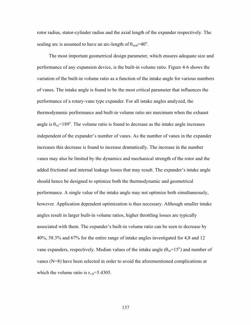
137
rotor radius, stator-cylinder radius and the axial length of the expander respectively. The
sealing arc is assumed to have an arc-length of θseal=40o.
The most important geometrical design parameter, which ensures adequate size and
performance of any expansion device, is the built-in volume ratio. Figure 4-6 shows the
variation of the built-in volume ratio as a function of the intake angle for various numbers
of vanes. The intake angle is found to be the most critical parameter that influences the
performance of a rotary-vane type expander. For all intake angles analyzed, the
thermodynamic performance and built-in volume ratio are maximum when the exhaust
angle is θex=189o. The volume ratio is found to decrease as the intake angle increases
independent of the expander’s number of vanes. As the number of vanes in the expander
increases this decrease is found to increase dramatically. The increase in the number
vanes may also be limited by the dynamics and mechanical strength of the rotor and the
added frictional and internal leakage losses that may result. The expander’s intake angle
should hence be designed to optimize both the thermodynamic and geometrical
performance. A single value of the intake angle may not optimize both simultaneously,
however. Application dependent optimization is thus necessary. Although smaller intake
angles result in larger built-in volume ratios, higher throttling losses are typically
associated with them. The expander’s built-in volume ratio can be seen to decrease by
40%, 58.3% and 67% for the entire range of intake angles investigated for 4,8 and 12
vane expanders, respectively. Median values of the intake angle (θin=15o) and number of
vanes (N=8) have been selected in order to avoid the aforementioned complications at
which the volume ratio is rv,b=5.4305.

138
The displacement volume of a circular rotary-vane expander may be computed for
any given set of input parameters detailed in Table 4-3. The control volume analyzed is
defined as the volume bounded by the stator-cylinder, rotor, leading and trailing vanes
and the two axial end-plates. Figure 4-7 illustrates the ideal cell volume variation as a
function of angular displacement for different numbers of vanes. The displacement
volume per revolution is the cut-off volume multiplied by the number of vanes. Figure 4-
8 shows the difference between the ideal and actual volume. By accounting for the
thickness of the vanes, tv=4.2 mm, a slight shift in the volume curve is observed. This
results in a deviation by as much as 89% and by as little as 1% at initial and at larger
angular displacements. It can also be seen from Figure 4-8 that the maximum ideal and
actual volume occurs at θ=184o and θ=180o respectively.
The condensing and evaporating pressures corresponding to 50oC and 0oC
condensing and evaporating temperatures are 1.942 and 0.498 MPa, respectively. This
corresponds to a process volume ratio of 14.74 if the refrigerant is assumed to be
expanded isentropically. Figures 4-9 and 4-10 illustrate the variation of the pressure
within the expander as a function of the volume within the expander for various intake
angles and numbers of vanes, respectively. The pressure is found to be greater than the
desired exhaust pressure primarily because the built-in volume ratio is not equivalent to
the process volume ratio. From Figure 4-9, it can be shown that built-in volume ratios of
8.16, 6.6 and 5.43 corresponding to intake angles of 5o, 10o and 15o, respectively,
correspond, to exhaust pressures 15%, 32.2% and 40% higher than the desired exhaust
pressure. Figure 4-10, illustrates how the number of vanes affects the pressure variation
in an expander for a given intake angle. It can be shown that built-in volume ratios of

139
4.083, 5.43 and 6.6 corresponding to 6, 8 and 10 vane expanders result in 53%, 40% and
26% higher exhaust pressures, respectively. These differences are primarily due to
inadequate built-in volume ratios of the expander and result in less desirable
thermodynamic performance. Unless a throttle valve or another means of expanding the
discharging fluid to the evaporating pressure is used, flashing and/or other losses are
imminent. For the purpose of this ideal analysis the losses due to under-expansion are not
included in the models developed and it is assumed that a throttle valve further expands
any under-expanded refrigerant to the evaporator pressure.
Independent of the built-in volume ratio, the optimum performance of an expander
is expected to occur when the mass flow of the working fluid is maximum. The
maximum mass flow-rate will likely have to be greater if the built-in volume ratio of the
expander is inadequate. Accurate models for the mass flow-rate of an actual expander
may be developed in which inlet area, exhaust area, velocity and density variations as a
function of angular displacement are modeled. Figure 4-11 shows the variation of the
mass trapped in the expander’s control volume as a function of angular displacement for
various intake angles. It can be seen that as the intake angle increases, the greater the
amount of mass in the control volume during the expansion process. This results from the
fact that the expander’s cut-off is delayed. These delays in cut-off are represented as lines
(a), (b) and (c) respectively. It is found that the mass in the control volume during
expansion is 50% and 28% higher for intake angles of θ=25o and θ=10o, respectively,
when compared with that of θ=5o.
Figures 4-12 and 4-13 show the variation of power extracted during the process
expansion as a function of angular displacement for various intake angles and different
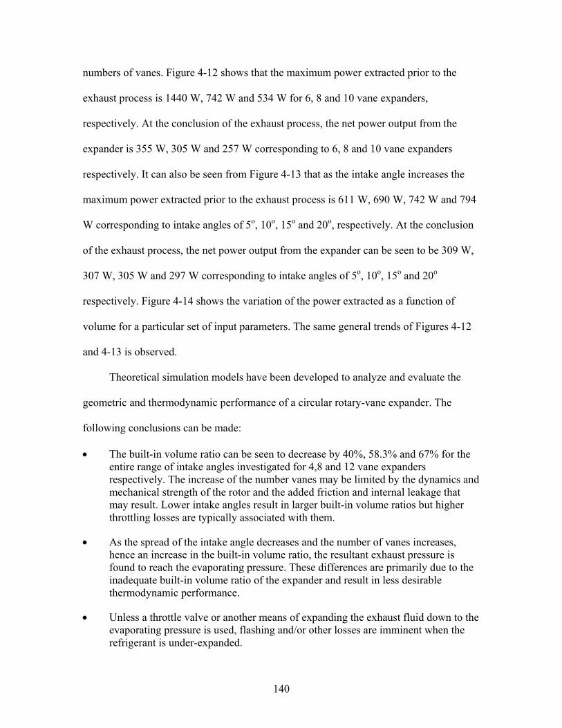
140
numbers of vanes. Figure 4-12 shows that the maximum power extracted prior to the
exhaust process is 1440 W, 742 W and 534 W for 6, 8 and 10 vane expanders,
respectively. At the conclusion of the exhaust process, the net power output from the
expander is 355 W, 305 W and 257 W corresponding to 6, 8 and 10 vane expanders
respectively. It can also be seen from Figure 4-13 that as the intake angle increases the
maximum power extracted prior to the exhaust process is 611 W, 690 W, 742 W and 794
W corresponding to intake angles of 5o, 10o, 15o and 20o, respectively. At the conclusion
of the exhaust process, the net power output from the expander can be seen to be 309 W,
307 W, 305 W and 297 W corresponding to intake angles of 5o, 10o, 15o and 20o
respectively. Figure 4-14 shows the variation of the power extracted as a function of
volume for a particular set of input parameters. The same general trends of Figures 4-12
and 4-13 is observed.
Theoretical simulation models have been developed to analyze and evaluate the
geometric and thermodynamic performance of a circular rotary-vane expander. The
following conclusions can be made:
• The built-in volume ratio can be seen to decrease by 40%, 58.3% and 67% for the entire range of intake angles investigated for 4,8 and 12 vane expanders respectively. The increase of the number vanes may be limited by the dynamics and mechanical strength of the rotor and the added friction and internal leakage that may result. Lower intake angles result in larger built-in volume ratios but higher throttling losses are typically associated with them.
• As the spread of the intake angle decreases and the number of vanes increases, hence an increase in the built-in volume ratio, the resultant exhaust pressure is found to reach the evaporating pressure. These differences are primarily due to the inadequate built-in volume ratio of the expander and result in less desirable thermodynamic performance.
• Unless a throttle valve or another means of expanding the exhaust fluid down to the evaporating pressure is used, flashing and/or other losses are imminent when the refrigerant is under-expanded.

141
• As the number of vanes increases, the net power output of the expander decreases. For the cases investigated, as much as 75% of the power extracted prior to the exhaust process is consumed by the exhaust process. Compared to a 10-vane expander the net work output of a 6-vane expander is found to be greater by as much as 27%
• As the intake angle increases, the maximum power extracted prior to the exhaust process increases. At the conclusion of the exhaust process, the net power output from the expander is found to deviate only 2% from the mean.
The thermodynamic model developed in this section was ideal in its assumptions
and analysis. It did not take into account losses that may arise due to throttling in the
intake and exhaust ports, two-phase internal leakage, friction, heat transfer, re-
compression or irreversible losses due to over- or under-expansion caused by inadequate
expander sizing. Chapter 5 details the theory and presents models of those
aforementioned loss mechanisms. Once described, the models for these loss mechanisms
will modify the thermodynamic model developed in this chapter to provide an accurate
estimate of the expander’s detailed and overall performance.

142
Figure 4-1. Flow diagram of the main computer program developed
Geometric and Kinematic Model
Thermo-physical Model
Friction Model
Internal Leakage Model
Throttling Model
Expander Model
Inputs: (from Vapor Compression System Model) -Pressure -Temperature
Outputs: (to Vapor Compression System Model) -Pressure -Temperature -Power Output -Volumetric Efficiency -Torque

143
Table 4-1. Summary of rotary-vane literature Analysis No. Investigator Application Working Fluid Eq of State
Geom
etrical
Thermodynam
ic
Friction
Internal Leakage
HeatTransfer
Lubrication
1 Peterson and McGahan (1972) Compressor Air Ideal-gas x x x x 2 Badr et al. (1985a) Expander in ORC General - x 3 Badr et al. (1985b) Expander in ORC R-113 Ideal-gas x 4 Badr et al. (1985c) Expander in ORC R-113 Ideal-gas x 5 Badr et al. (1986a) Expander in ORC R-113 Ideal-gas x 6 Badr et al. (1986b) Expander in ORC R-113 Ideal-gas x 7 Edwards and McDonald (1972) Expander in ROVAC Air Ideal-gas x 8 Robertson and Wolgemuth (1978) Expander in RC Steam Ideal-gas x x x 9 Beck et al. (1966) Compressor in VC R-12 vapor na x 10 Marsters and Ogbuefi (1972) Air Motor Air Ideal-gas x x 11 Somayajulu (1971) Pump Air Ideal-gas x x x 12 Ben-Bassat and Wolgemuth (1972) 2-stage Exp in RC Steam K & K* x x x 13 Wolgemuth and Olson (1971) Expander in RC Steam K & K* x x x 14 Jacazio et al. (1979) Air Motor Air Ideal-gas x x 15 Bransford and Stein (1960) Compressor in VC Air and R-12 Ideal-gas x x 16 Robertson and Wolgemuth (1975) Expander in RC Steam Ideal-gas x x x x x 17 Barszcz, Z. (1980) Air Motor Air General x x VC: Vapor Compression refrigeration system RC: Rankine Cycle ORC: Organic Rankine Cycle ROVAC: ROtary Vane Air refrigeration Cycle *Keenan and Keyes equation of state for steam
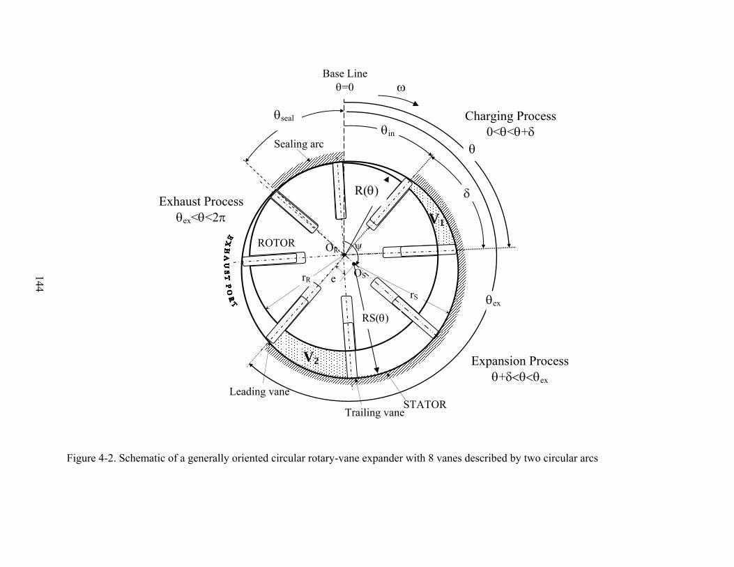
144
Figure 4-2. Schematic of a generally oriented circular rotary-vane expander with 8 vanes described by two circular arcs
Sealing arc
Trailing vane STATOR
Leading vane
ROTOR
θin
θ
θex
δ
ω
OS
OR ψ
e rR
V2
V1
rS
θseal
RS(θ)
R(θ)
Charging Process 0<θ<θ+δ
Expansion Process θ+δ<θ<θex
Exhaust Process θex<θ<2π
Base Line θ=0

145
Table 4-2. Geometrical input parameters
Input Parameter Symbol Rotor radius, m rR Eccentricity, m e Angle between rotor and stator-cylinder centers ψ Stator cylinder radius, m rS=rR+e Axial length of expander, m L=AR.rR Number of vanes N Angle between successive vanes, deg δ=360o/N Thickness of vanes, m tv Inlet port arc-length, deg θin Exhaust port arc-length, deg θex Arc-length of sealing arc, deg θseal

146
Figure 4-3. Variation of the inlet throat area with respect to angular displacement
Figure 4-4. Variation of the exit throat area as a function of angular displacement for an
8-vane circular MVE
0
0.0005
0.001
0.0015
0.002
0.0025
0.003
0 20 40 60 80 100
Angular Displacement, deg
Inle
t Thr
oat A
rea,
m2
0
0.0005
0.001
0.0015
0.002
0.0025
0.003
150 200 250 300 350 400
Angular Displacement, deg
Exit
Thro
at A
rea,
m2

147
Figure 4-5. Pressure variation as a function of volume in an ideal expander for the cases of ideal, over and under expansion.
+θ θ δ ex
P
P
inbuitvprocessv rr −= ,,P
V
int
ex
in in θ
Ideal Expansion
Under Expansion
Over Expansion
inbuitvprocessv rr −> ,,
inbuitvprocessv rr −< ,,
+θ θ δ ex
P
P
inbuitvprocessv rr −= ,,P
V
int
ex
in in θ
Ideal Expansion
Under Expansion
Over Expansion
inbuitvprocessv rr −> ,,
inbuitvprocessv rr −< ,,
+θ θ δ ex
P
P
inbuitvprocessv rr −= ,,P
V
int
ex
in in θ
Ideal Expansion
Under Expansion
Over Expansion
inbuitvprocessv rr −> ,,
inbuitvprocessv rr −< ,,
θ θ δ ex
P
P
inbuitvprocessv rr −= ,,P
V
int
ex
in in θ
Ideal Expansion
Under Expansion
Over Expansion
inbuitvprocessv rr −> ,,
inbuitvprocessv rr −< ,,
P
P
inbuitvprocessv rr −= ,,P
V
int
ex
in in θ
Ideal Expansion
Under Expansion
Over Expansion
inbuitvprocessv rr −> ,,
inbuitvprocessv rr −< ,,
inbuitvprocessv rr −= ,,P
V
int
ex
in in θ
Ideal Expansion
Under Expansion
Over Expansion
inbuitvprocessv rr −> ,,
inbuitvprocessv rr −< ,,

148
Table 4-3. Typical operating conditions for a basic and modified 2 ton system
*R-22, 2 ton cooling capacity, Tcond=50oC, Tevap=0oC, ηc=0.85, no superheat, no subcooling, pressure losses in lines and components neglected
Expander
Isenthalpic Expansion ηexp=0.45 ηexp=0.85
Isentropic Expansion
,g/s 49.6 48.61 47.77 47.5
v3, m3/kg 0.000924 0.000924 0.000924 0.000924
rv,p 16.3 15.6 14.97 14.74 COP 3.52 3.87 4.23 4.38
ηref, % 64.4 70.8 77.4 80.1
wexp, kJ/kg - 2.89 5.46 6.42
wnet, kJ/kg 40.3 37.4 34.8 33.8
qevap, kJ/kg 141.1 144.7 147.3 148.2
refm&

149
Figure 4-6. Variation of built-in volume ratio as a function of intake angle for different numbers of vanes
Figure 4-7. Variation of ideal volume as a function of angular displacement for different
numbers of vanes
0.0E+00
5.0E-07
1.0E-06
1.5E-06
2.0E-06
2.5E-06
3.0E-06
3.5E-06
0 60 120 180 240 300 360
Angular Displacement θ, deg
Idea
l Vol
ume,
m3
N=4
N=6
N=12
N=8
N=10
AR=0.46rR=27.9 mme=2.7 mmθin=15o
θout=189o
0
2
4
6
8
10
10 15 20 25 30
Intake Angle θ in, deg
Bui
l-in
Volu
me
Rat
io r
v,b N=4
N=6N=8N=10N=12

150
Figure 4-8. Variation of ideal and actual volumes as a function of angular displacement
Figure 4-9. Variation of pressure as a function of volume for various intake angles
0
500
1000
1500
2000
2500
0.0E+00 5.0E-07 1.0E-06 1.5E-06 2.0E-06
Volume, m3
Pres
sure
, kPa
AR=0.46rR=27.9 mme=2.7 mmN=8θout=189o
Pinlet
Pexhaust
} Losses}}
θin=5o
θin=10o θin=15o
0.0E+00
4.0E-07
8.0E-07
1.2E-06
1.6E-06
2.0E-06
0 100 200 300 400
Angular Displacement θ, deg
Volu
me,
m3
Ideal
Actual
AR=0.46rR=27.9 mme=2.7 mmN=8θin=15o
θout=189o
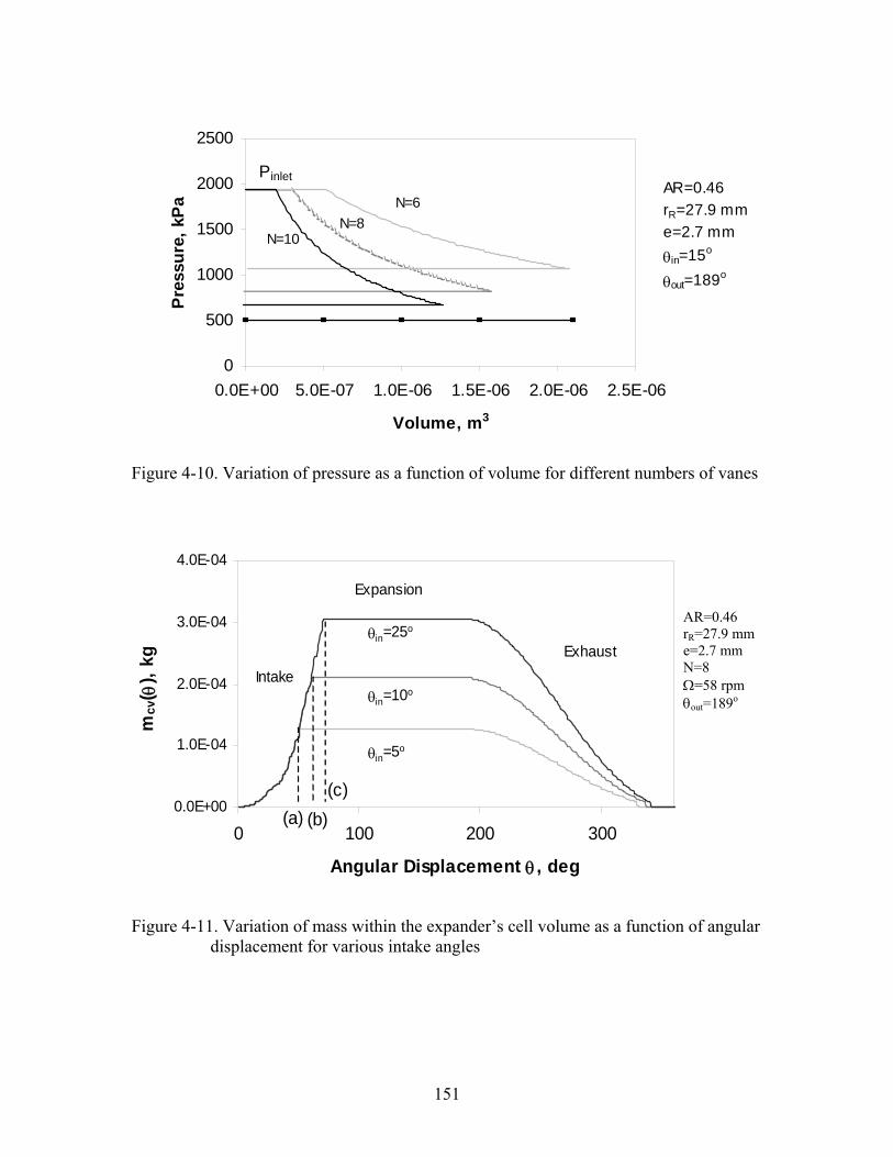
151
Figure 4-10. Variation of pressure as a function of volume for different numbers of vanes
Figure 4-11. Variation of mass within the expander’s cell volume as a function of angular displacement for various intake angles
0
500
1000
1500
2000
2500
0.0E+00 5.0E-07 1.0E-06 1.5E-06 2.0E-06 2.5E-06
Volume, m3
Pres
sure
, kPa
PinletAR=0.46rR=27.9 mme=2.7 mmθin=15o
θout=189o
N=10
N=6N=8
0.0E+00
1.0E-04
2.0E-04
3.0E-04
4.0E-04
0 100 200 300
Angular Displacement θ , deg
mcv
( θ),
kg
θin=25o
θin=5o
θin=10o
Expansion
ExhaustIntake
(a) (b)(c)
AR=0.46 rR=27.9 mm e=2.7 mm N=8 Ω=58 rpm θout=189o

152
Figure 4-12. Variation of power as a function of angular displacement for different numbers of vanes
Figure 4-13. Variation of power as a function of angular displacement for various intake angles
0
0.2
0.4
0.6
0.8
1
1.2
0 120 240 360
Angular Displacement θ ,deg
Pow
er, k
W
N=10
N=8
N=6
Net Pow erOutput
AR=0.46 rR=27.9 mm e=2.7 mm Ω=58 rpm θin=15o θout=189o
0
0.2
0.4
0.6
0.8
1
0 120 240 360
Angular Displacement θ , deg
Pow
er, k
W
θin=20o
AR=0.46rR=27.9 mme=2.7 mmN=8Ω=58 rpmθout=189o
θin=5o
θin=10o
θin=15o
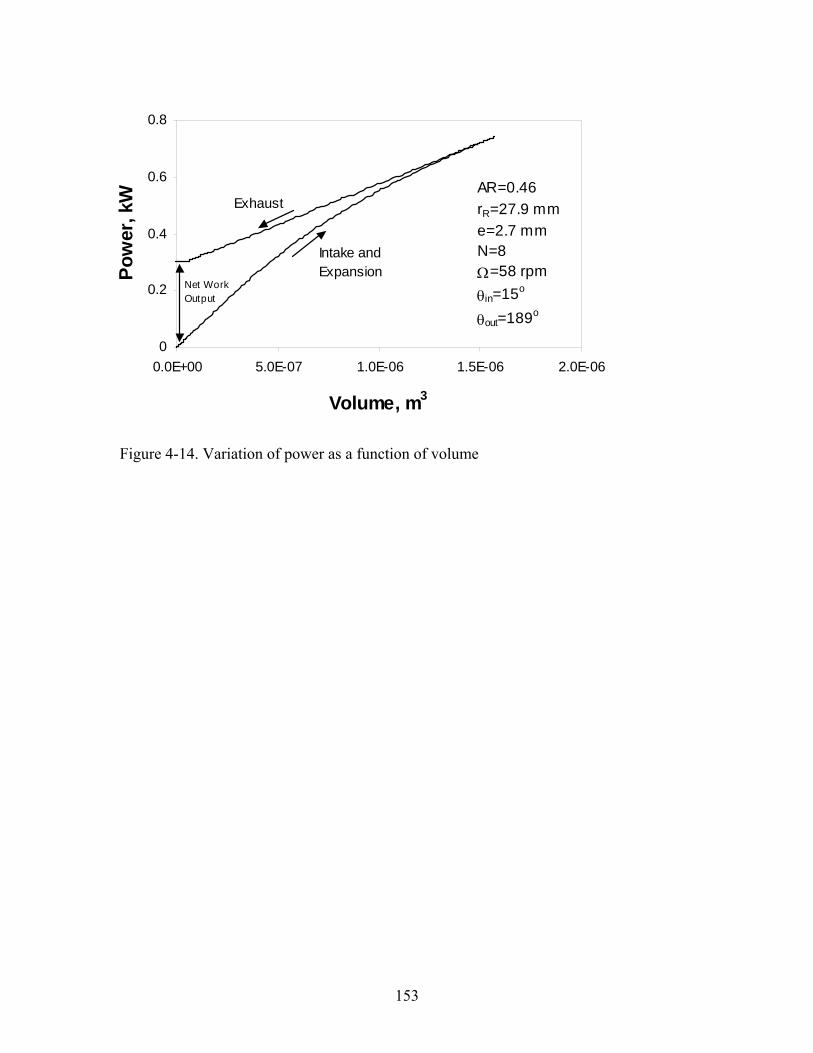
153
Figure 4-14. Variation of power as a function of volume
0
0.2
0.4
0.6
0.8
0.0E+00 5.0E-07 1.0E-06 1.5E-06 2.0E-06
Volume, m3
Pow
er, k
W
Intake and Expansion
Exhaust
Net Work Output
AR=0.46rR=27.9 mme=2.7 mmN=8Ω=58 rpmθin=15o
θout=189o
154
CHAPTER 5 PRIMARY AND SECONDARY LOSS MECHANISMS IN ROTARY-VANE TWO-
PHASE REFRIGERATING EXPANDERS
All turbomachinery operate with energy and mass losses. These losses may be
attributed to two-phase internal leakage, friction, throttling losses in the intake and
exhaust ports, re-compression in the expander cavity and over- or under-expansion due to
inadequate sizing of the geometric volume ratio.
Primary Loss Mechanisms
The aim of this chapter is to develop mathematical models that would account for
the primary loss mechanisms of internal leakage and friction. The size of a rotary-vane
expander is of primary interest due to the influence it has on the magnitude of loss
mechanisms present. While rotary-vane compressors are typically very efficient, at
smaller sizes, the effect of losses such as internal leakage becomes much larger. In rotary-
vane expanders of smaller sizes both the volumetric and adiabatic efficiencies are
expected to be smaller. Depending on the operational and geometrical parameters of the
expander, laminar and viscous two-phase leakage flow within the expander may be
present. Single-phase leakage models available in the literature must be revisited and
modified accordingly. A dynamic frictional model for the expander must also be
developed for ideal operation (i.e. no internal leakage) and modified to account for
internal leakage accordingly. A comprehensive component-level model of inherent
friction and internal leakage losses in a two-phase circular rotary-vane expander used in a
vapor compression refrigeration system is presented. The model establishes the efficiency
and performance of the expander as a function of geometric and fluid parameters.
Accurate modeling and prediction of frictional and internal leakage losses is vital to

155
being able to accurately estimate the efficiency, rotational speed, and the torque and
power produced by the expander.
Internal Leakage Paths and Clearances
The clearances between the rotor and stator cylinders, end-plates and vanes provide
the necessary seals of the expander cavity. Caution must be exercised when designing an
expander’s assembly clearances. Depending on the operating conditions and geometric
volume ratio, large temperature gradients may also lead to thermal deformations of these
materials. The clearances must be minimized for each application to ensure control of
internal leakage losses yet re-compression of liquid may lead to inadequate operation or
“liquid locking”. The various leakage paths are tabulated in Table 5-1.
The volumetric efficiency of an expander may be larger than unity due to
significant increases in the consumption of the working fluid. This significant increase is
primarily a result of internal leakage losses. The magnitude and sources of internal
leakage must be identified and minimized. The magnitude and sources of internal leakage
is significantly dependent upon the way by which the working fluid is introduced into the
expander’s cavity. Figure 5-1 illustrates the difference between the conventional (a) and
modified (b) methods through which the fluid is introduced into the expander’s cavity.
The “conventional” intake port is machined directly into the stator-cylinder. The
“modified” intake is comprised of slots machined in both end-plates after which the fluid
is introduced into the expander’s cavity via a slot machined into the rotor at a specific
angle from the slot.
Upon the completion of the geometric, kinematic and thermodynamic models, the
predicted pressure and quality of the refrigerant in the expander’s control volume are
used to calculate the leakage of refrigerant through the various leakage flow paths. In

156
order to model internal leakage between control volumes, the flow areas of the leakage
paths, Aleak, must be estimated. The mass flow-rate of internal leakage can be written in
general form as
( ) ( ) ( ) ( )leak d leak leak leakm C A uθ ρ θ θ θ=& (5-1)
where Cd is an empirical discharge coefficient. The density and velocity of the leakage
are a function of the angular displacement at which the leakage occurs and the
thermodynamic state of the fluid. Of primary interest is the computation of the velocity.
The net mass flow leaked into the cavity formed by the adjacent vanes, stator and rotor
cylinders (see Figure 5-1) can be computed as
( ) ( ) ( )leak leak leakm m mθ θ δ θ= − −& & & (5-2)
Leakage from Path (6) is neglected. It should be noted that if the sealing arc is
symmetric about the base line then ψ=180o and RS(θ)=rS.
Types of Two-Phase Leakage Losses
The majority of internal leakage models in turbo-machinery presented in recent
literature are developed for single-phase compressible flow. The friction associated with
incompressible leakage losses through a duct or leakage path of constant cross-sectional
area affects only pressure in the direction of the flow. The velocity of the working fluid
remains constant. According to Oothusizen (1997), in compressible flow, friction affects
all of the flow variables, i.e., the changes in pressure cause changes in density which lead
to changes in velocity For two-phase flow this also necessitates vaporization of liquid,
which alters the density of the working fluid significantly. Depending on the operational
and geometrical parameters of the expander, turbulent two-phase leakage flow within the
expander may be present.

157
In the case of two-phase viscous leakage losses, the two-phase mixture is assumed
to be homogenous in nature. The idealizations adopted under this fairly common model
include assuming that the vapor and liquid velocities are equal. The over-all two-phase
flow is also assumed to behave like a single phase, uniformly mixed, having fluid
properties whose values are, in some sense, mean values for the flow according to Carey
(1992). According to Levy (1999), assuming homogenous flow also allows the ability to
apply all available single-phase flow analyses and empirical correlations The density of
the homogenous two-phase mixture is computed as
1 1
g f
x xρ ρ ρ
−= + (5-3)
The calculation of other necessary properties for the two-phase mixture, such as the
specific heats and viscosity, can be very troublesome. Many different formulations have
been proposed throughout the literature. Among them,
( )1 f gx xμ μ μ= − + (5-4)
1 1
g f
x xμ μ μ
−= + (5-5)
( )1g f
g f
x xμ μμρ ρ ρ
−= + (5-6)
For example, a two-phase mixture of water at P=500 kPa and x=0.2 yields a viscosity of
146.09, 53.52 and 15.968 μPa.s from Equations (5-4), (5-5) and (5-6), respectively.
According to Carey (1992), Equation (5-5) is the most common. Properties can also be
computed by utilizing the concept of the homogenous void fraction α,
158
( )1f
f g
xx x
ρα
ρ ρ=
+ − (5-7)
and hence the dynamic viscosity can be computed from ( )1f gμ μ α μ α= − + . This method
will be used since the computed value is identical to that obtained from Equation (5-6). In
the same manner the specific heats and thermal conductivity can be computed.
Viscous effects must be accounted for when computing the pressure drop and mass
flow-rate through radial clearances, e.g. flow through minimum clearance. These
channels are typically long and wide when compared to the height of the channel.
Viscous effects may be neglected when dealing with nozzles or short ducts. The axial
leakage flow between the vanes and the end-plates is an example where viscous effects
may be neglected. The flow of the two-phase compressible leakage, accounting for
friction, can be modeled as adiabatic Fanno-flow.
Figure 5-2 shows a schematic of a typical leakage path. The dimensions of the
leakage path, cross-sectional area and length, are known and depend on the leakage path
under consideration. The exit, (e), could be choked depending on the difference between
the pressure of the reservoir and back pressure at local angles θ and θ+δ, respectively.
Darby (2001) concludes that the ratio of the sonic velocity in a homogenous mixture to
that in a gas alone is much smaller than unity. In this case choking can occur in a two-
phase mixture at a significantly higher downstream pressure. This corresponds to both a
lower pressure drop and mass flux.
The flow is choked when the velocity at the exit plane is equal to the speed of
sound. For a non-flashing liquid and an ideal gas mixture, the maximum mass flow-rate

159
in the channel can be computed. The isentropic speed of sound for a homogenous two-
phase mixture can be computed as
s
Pa ⎛ ⎞∂= ⎜ ⎟∂ρ⎝ ⎠
(5-8)
The governing equations and the discretized form of those equations are presented
in Table 5-2 and are derived from first principles and describe adiabatic Fanno flow from
a reservoir.
It should be noted that the volume of the leakage channel is V=Hwl and the mass
flow-rate through the channel is e em u Hwρ=& . The Darcy friction factor, f, is assumed
constant over the length of the leakage channel. This is a fairly reasonable assumption
since the flow is typically found to be fully developed over a majority of the channel
length. For Reynolds numbers in the lower range of the turbulent region, the modified
Blasius correlation is
0.250.33ReHf −= (5-9)
where the Reynolds number is defined as ReH e eu H v= . This correlation has been
shown to be in good agreement with various experiments throughout the literature. The
momentum equation can therefore be expressed by
( )1.75
21 0.75 1.250.165 e
e e ee
luP P uv H
ρ− − = (5-10)
The methodology used to solve for adiabatic Fanno-flow through a leakage path is
an iterative procedure. The state of inlet to the channel is known. Depending on the
leakage path and the state of the refrigerant, the flow may be of an incompressible liquid
or a compressible two-phase refrigerant. The unknowns, in Equation (5-10), that remain

160
are ue, m& , Pe and ρe. The iterative procedure calls for an initial guess at the exit plane of
the channel where the flow is assumed to be choked. An initial guess of the pressure at
the exit plane may correspond to the average pressure that exists in the adjacent expander
cell. The flow is assumed to be isenthalpic or isochoric in the case of two-phase or liquid
flow, respectively. In the case of the two-phase flow the quality is known. Based on the
initial guesses, the speed of sound can be calculated. If the flow is choked at the exit
plane, i.e ue=a, then P is iterated upon until Equations (5-5), (5-8) and (5-10) are satisfied
simultaneously.
If the flow is viscous and the exit plane is unchoked, the average velocity of the
leakage can be determined by solving generalized Couette flow, see Figure 5-3, the flow
is driven by both the shear of a moving wall and a given pressure differential. Solving the
momentum equation and applying the no-slip and moving wall boundary conditions the
velocity distribution is
21( ) ( )m
dP ru y y y ydx
ωδμ δ
= − + (5-11)
The mean velocity between the plates is defined as
( )0
1m
y
u u y dyδ
=
=δ ∫ (5-12)
and after integration is found to be 2
2 12mm
r dPudx
ω δ= −
μ (5-13)
If the flow in the leakage path can be modeled as isentropic flow through a nozzle
whose throat is choked then the initial guess used to evaluate the sonic velocity is
1i
eP P= and 1es s= . The density is then calculated. The pressure and density at isentropic

161
conditions, at the exit plane, are iterated upon accordingly until the computed speed of
sound is identical to the relationship obtained from the energy equation, 12( )e eu h h= − . In
the case that the isentropic flow is unchoked, the exit plane pressure is equal to the back-
pressure, Pe=Pb and se=s1. The thermodynamic state at the exit plane can then be
established and the velocity at the exit can be determined by Equation (5-8).
Axial Clearance Between Rotor and End Plates
The flow of the fluid between the rotor and end-plates can be modeled as that of a
fluid flowing in a narrow gap between a disc which rotates within a chamber of finite
dimensions. The boundary conditions imposed on the periphery of the rotating disk are
non-axisymmetric in nature due to the pressure distribution of the fluid in the expander’s
cavity. The effects of the vanes and their slots are neglected. The characteristics of the
flow as well as the complexity of the solution can vary significantly depending on the
order of magnitude of several key dimensionless variables. The dimensionless governing
equations yields key dimensionless groups that govern the flow and are found to be the
local rotational (disk) Reynolds number in terms of δ1, the Euler number and the gap
aspect ratio, S. If the rotational speed of the rotor is ω in rad/s then these parameters are
defined as
1
RrSδ
= (5-14)
2 2m R
PEurρ ω
Δ= (5-15)
21Re
mδ
ωδν
= (5-16)

162
where ΔP in the Euler number corresponds to the maximum pressure differential on the
rotor’s outer boundary, i.e. the intake and exhaust conditions. It should also be noted that
in rotating disk problems the rotational Reynolds number is utilized instead of the radial
Reynolds number which is defined as 1Re R mr vω δ= . For the same flow conditions, the
use of the latter is typically three orders of magnitude larger.
Daily and Nece (1960) have identified four different modes of flow for given
geometrical and flow characteristics. Of interest in this study are the laminar and
turbulent cases corresponding to a close gap where boundary layers on the rotor and end-
plate are merged. In this case a continuous variation of the velocity across the axial gap
exists. The rotational Reynolds number must be small in the gap, 1
Re 1δ < , for this type of
flow to exist. Separate boundary layers exist when the axial gap exceeds the total
thickness of the two boundary layers. The condition for laminar flow can therefore be
estimated from Daily and Nece (1960) as 1
2 5Re 10Sδ ⋅ < . The Euler number which is
defined as the ratio of the maximum pressure differential to the centrifugal pressure
produced during rotation is assumed large, i.e.1
Re 1Eu δ⋅ > . The gap aspect ratio must also
be substantially larger than unity. If these four conditions can be satisfied simultaneously
then a zeroth-order solution approximates the solution to the Navier-Stokes equations.
This solution consists of a power series of Reδ1, e.g. 1 1
20 1 2Re Re ...u u u uδ δ= + + + ,
expanded around the asymptotic solution of Reδ1 approaching zero. Bein et al. (1976)
concluded that this is a reasonable assumption for 20Eu ≥ .
It must be determined whether the following analysis is valid for the flow of two-
phase fluid in the axial gap. Due to the vaporization of liquid in the expander’s cavity, the
thermodynamic properties vary significantly. Coupled with the significant variation of

163
intake and exhaust parameters, geometry of the leakage gap and rotational speed of the
expander, the aforementioned constraints may not be satisfied. In order to determine the
operational conditions under which the analysis is valid the following operational
parameters considered are presented in Table 5-3. It can be shown that the flow is laminar
for all parameters investigated at lower rotational speeds, i.e. Ω<500 RPM. Depending on
the geometric size of the expander, the expander’s actual rotational speed realistically
doesn’t exceed this value. Based on the analysis of these operational conditions, an order
of magnitude analysis of the flow dimensionless parameters is presented in Table 5-3. It
maybe concluded that the zeroth-order solution is appropriate.
The location of the phase interface in rotating, eccentric complex geometries is
very difficult to predict. If sufficient centrifugal forces are produced due to high
rotational speeds it may be assumed that the majority of the leakage-flow in the axial gap
is vapor. This arises due to the tendency of the dense liquid to flow in the vicinity of the
stator-cylinder wall due to significant centrifugal forces. Hence the incompressible form
of the general equations with constant properties, evaluated at some mean value, is used.
Neglecting body forces, terms of order 1/S2 and equating terms with Reδ1, the zeroth-
order dimensionless 3-D Navier-Stokes equations in cylindrical coordinates are solved in
order to determine the velocity and pressure field within the narrow gap. If a gap width δ1
exists between the rotor and the end plates, then the dimensionless governing equations
can be reduced and written as follows
( ) 0 00
1 1 0v wrur r r zθ
∂ ∂∂+ + =
∂ ∂ ∂ (5-17)
1
20 0
2 Reu pEuz rδ
∂ ∂=
∂ ∂ (5-18)

164
1
20 02
1Rev pEuz rδ θ
∂ ∂=
∂ ∂ (5-19)
0 0pz
∂=
∂ (5-20)
where the dimensionless variables are defined in the nomenclature. According to
Equation (5-20), ( )0 0 ,P P r θ= . The boundary conditions can be written as follows,
( , , 0) 0ou r zθ = =
0 ( , , 0) 0v r zθ = =
( , , 0) 0ow r zθ = = (5-21)
( , , 1) 0ou r zθ = =
0 ( , , 1)v r z rθ = =
( , , 1) 0ow r zθ = = (5-22)
( 1, ) ( )o cvP r P= =θ θ
00 ( , ) ( , ) 0Pu r r
r∂
= = = =∂
β θ β θ (5-23)
where Pcv(θ) is a linear piece-wise function that closely approximates the actual pressure
distribution around the rotors outer boundary and is presented in Figure 5-4.
A linear approximation first presented by Bein et al. (1976) and furthered by Badr
(1985) for a typical pressure profile is compared to numerically integrated Fourier
constants in Equation (5-25). It can be shown that 100 terms in the summation of the
Fourier constants yield the actual pressure distribution. Depending on the geometric
volume ratio of the expander, the difference between the linear approximation and can
vary significantly. An expander with a volume ratio of rv=3.916 is analyzed in Figure 5-4

165
and a maximum difference of 40% is found to exist between. This greatly influences the
accuracy of the computed radial velocity.
The zeroth-order solution of the following simplified set of equations and satisfying
all necessary boundary conditions yields Bein et al. (1976) as such
1 200
Re( )
2Eu Pu z z
rδ ∂
= −∂
(5-24)
1 200
Re 1 ( )2
Eu Pv z z rzr
δ
θ∂
= − +∂
(5-25)
Substituting Equations (5-24) and (5-25) into the continuity equation, Equation (5-17),
and applying the boundary conditions in the axial direction yields
20 0P∇ = (5-26)
Solving Equation (5-26) by means of separation of variables, the general solution for the
pressure distribution in the gap is
( )0 0 0
1
( , ) ln
cos ( )sinn n n nn n n n
n
P r a b r
a r b r n c r d r n
θ
θ θ∞
− −
=
= + +
⎡ ⎤+ + +⎣ ⎦∑ (5-27)
The Fourier constants can be determined from the specification of the pressure
distribution on the outer boundary of the rotor (see discussion of Figure 5-4). The radial
velocity distribution can be found by differentiating Equation (5-27) with respect to the
radial direction and substituting that result into Equation (5-23). The total dimensional
leakage mass flow-rate in the radial direction with respect to the rotor is
( ) ( ) ( ) 2,1 0 12 1,leak cv Rm u r r= =& θ ρ θ θ ω δ (5-28)

166
The value of the mass flow-rate is negative if the flow leaves the expander cell.
This model doesn’t take into account choking, which is likely, since the velocity
distribution at the rotor’s outer boundary is of primary interest.
Leakage around tips of vanes
Depending upon on the method by which the high pressure refrigerant is introduced
into the expander’s cavity; see Figure 5-1, leakage due to insufficient under-vane fluid
pressure or inadequate force/absence of mechanical springs may lead to significant
leakage losses several orders of magnitude larger than other leakage paths. Continuous
and sufficient contact between the vanes and the stator-cylinder is necessary to subdue or
minimize this type of leakage. The majority of leakage of this type may occur during the
intake process where low rotational speeds cause inadequate centrifugal forces to keep
the vanes in contact with the stator-cylinder. The existence of both low rotational speeds
and inadequate under-vane pressure can be predicted by the frictional model developed.
The frictional model is presented later in this chapter. It should be noted that the reaction
force, Fn(θ) (see Figure 5-5), is predicted by the friction model and accounts for, among
other things, the sliding velocity and acceleration of the protruding vanes as well as the
under-vane pressure. If the vane has lost contact with the stator-cylinder, the value of this
normal force is negative, and the leakage flow area would be computed as
( ) 2 ( ) ( )leakA L X Lθ δ θ θ= = (5-29)
where X(θ) is the instantaneous protrusion of the vane from the rotor slot at the angular
rotation of the rotor where the loss of contact has occurred.
When the vanes establish contact with the cylinder it is assumed that the leakage
area is negligible and that this occurs until the start of the sealing arc. There may exist
167
leakage around the tips of the vanes during the spread of the sealing arc due to a
clearance gap δ3 between the stator-cylinder and rotor that may be due to an assembly
clearance or due to machining limitations. This radial leakage is treated in the next
section.
Due to the short nature of this leakage path, tv, the leakage of the two-phase fluid in
this path is assumed to be that of fluid in a convergent-divergent nozzle, i.e. isentropic
flow. It should be noted that if the incoming fluid is introduced into the rotor’s slots than
the internal leakage associated with weak under-vane pressure can be neglected. For this
design, internal leakage around the tips of the vanes can be neglected. The high-pressure
incoming refrigerant is first used to provide sufficient under-vane pressure so that
continuous contact between the vane and stator-cylinder may be achieved.
Leakage past the sides of the vanes
In general, the axial width of this leakage path may be estimated by accounting for
the thermal expansion of the vanes in addition to the gap that exists due to the thickness
of gaskets, δg and other assembly clearances. The operational length of the vane can be
computed from the known material’s coefficient of linear thermal expansion,
, ,v v o v v oL L L Tα− = Δ , and the temperature difference that the vane encounters relative to
ambient conditions. The mean temperature of the vane is computed as the average
temperature of two adjacent cells. It can be shown that even at the moderate temperature
differences realized within an expander’s cavity this effect accounts for a 0.3% change in
the length of the vane and is therefore neglected. The axial width of the leakage path is
assumed constant and equivalent to the gasket thickness
( )3 gδ θ δ= (5-30)

168
The height of this leakage channel is estimated by subtracting the height of the gap
realized due to leakage around the vane tips, if any, upon loss of contact with the stator-
cylinder, δ2(θ). The total leakage flow area is then calculated as
( ) ( )2 3( ) 2 ( )leakA Xθ θ δ θ δ θ⎡ ⎤= −⎣ ⎦ (5-31)
Due to the short nature of this leakage path, tv, the leakage of the two-phase fluid in this
path is assumed to be that of fluid in a convergent-divergent nozzle, i.e. isentropic flow.
Leakage between the faces of the vanes and the side walls of the rotor’s slots
The leakage from this path is typically neglected due to the existence of two contact
lines across the axial length of the rotor slots. These contact lines result from the reaction
forces FL(θ) and FR(θ) (see Figure 5-5). Negative reaction forces predicted by the friction
model represent a loss of contact between the vane and the rotor slot. The control volume
to which the mass and energy are added or subtracted depends on which vane face the
loss of contact occurs. If the fluid intake is through the rotor slot the leakage through this
path may be significant and comparable to other paths. Viscous effects need to be
considered since the leakage flow path is wide and long, Hv. The leakage flow area is
computed as
( ) ( )leak s vA t t Lθ = − (5-32)
The Leakage from the expander to the cavity beneath the vane may also be comparable if
ts-tv is large.
Leakage in radial gap between the rotor and stator cylinder
As the pressure differential between the intake and exhaust ports increases and the
number of vanes decreases, this leakage is typically the largest contributor to internal
leakage.

169
This leakage flow path arises if the angle between successive vanes is larger than
the spread of the sealing arc (spread of minimal clearance) between the rotor and stator-
cylinder i.e. sealθ δ> . If this is the case, the expander cell is in simultaneous contact with
the intake and exhaust ports. This overlap causes leakage flow from the inlet to the
exhaust ports against the direction of rotation. The severity of this leakage path is a
function of the number of vanes and the mean radial gap height δ4 that exists between the
rotor and stator-cylinder due to assembly operations or machining limitations. This
leakage flow path would occur for the leading vane’s angular displacement of
0 sealθ δ θ< < − . The flow in this leakage path is modeled as adiabatic, one-dimensional
Fanno-flow. It should be noted that leakage through this path can only be neglected if
sufficient centrifugal forces or under-vane pressure exists to maintain continuous contact
of the vane with the stator-cylinder. Typically an insufficient under-vane force exists due
to the absence of high-pressure fluid (or presence of low-pressure residual fluid) due to
the theoretical completion of the exhaust process. The magnitude of the normal force
Fn(θ) determined by the frictional model aids in this prediction. The flow in this leakage
path would necessarily be choked for large geometric volume ratios or uncontrolled
expansion in the exhaust port if no throttle valve is downstream of the expander.
Friction Model
Prediction of the power output and developed torque of the rotary-vane expander
requires accurate modeling of frictional losses incurred in the expander. The primary
frictional losses in the rotary-vane expander result from:
• Rubbing of the vanes against the stator-cylinder
• Rubbing of the vanes against the walls of their rotor’s slots
170
• The resultant viscous drag acting on both sides of the rotor from the leakage flows through the axial gaps between the rotor and the end-plates.
A steady-state mathematical model that predicts frictional losses within a rotary-
vane expander must be coupled with geometric, thermodynamic and to leakage models in
order to provide for a better estimate of the mechanical efficiency and actual power
produced by the expander. A general dynamic model that incorporates the main sources
of friction within the rotary-vane expander is presented in this section. Effects of pressure
forces, reaction forces, sliding friction, viscous drag, gravity and inertial forces must all
be accounted to understand the relevance and magnitude of these effects. Figure 5-5 is a
schematic of a free body diagram of a vane protruding out a rotor slot at a local angle θ.
In order to model frictional losses in a rotary-vane expander, vane forces resulting
from pressure loading, vane inertia and body forces due to radial and Coriolis
accelerations must be determined. Sliding friction must also be considered between the
vanes and the rotor slots and stator-cylinder. These forces and frictional losses
continuously change, in both magnitude and direction throughout the expander due to
continuous changes in complex geometry.
The dynamic model developed assumes that the vanes are rigid and that the
coefficient of friction is constant. The conditions for dynamic equilibrium are solved
simultaneously to determine the unknown reaction forces based on a free-body diagram
of a single vane. Upon determining the reaction forces, the power required to overcome
the resisting frictional forces can be computed. Below is a detailed description of the
various forces as well as simplifying assumptions that have been made.
A pressure force on the base of the vanes is assumed to act at mid-thickness of the
vane as a result of incoming fluid pressure or a spring force utilized to maintain vane-tip

171
and stator-cylinder contact. This pressure force at the vane base can be expressed as
follows
b inlet vF P t L= λ (5-33)
where λ is a proportionality constant that can be evaluated from calculating throttling
losses to or from the cavity beneath the vane. If the fluid is introduced directly into the
rotor slots for the spread of the intake port, θin, and assuming no throttling losses then
λ=1. If the fluid is introduced into the expander’s cavity directly then throttled leakage
flow will provide the pressure force on the vane base (e.g. λ=0.75). If correctly sized and
assembled springs or a means for adequate pressurization of the slots are used then λ=1.
The pressure forces exerted on the vanes from either side FPR and FPL can be
expressed as ( ) ( ) ( )PL cvF P X Lθ = θ θ and ( ) ( ) ( )PR cvF P X Lθ = θ + δ θ respectively. If
leakage losses through the vane rotor-slot gaps are neglected then these pressure forces
are assumed to act mid-way between the rotor’s outer boundary and stator-cylinder’s
wall. If a gap exists between the vanes and the rotor slots, the orientation of the pressure-
loaded vane, see exaggerated effect in Figure 5-5, provides two sealing surfaces. The
portion of the vane that protrudes from the slot is denoted by X(θ).
The reaction forces FL(θ) and FR(θ) are assumed to act at the points of contact of
the vane and the rotor slots on the left and right faces of the slot, respectively. These
forces are actually distributed along a finite distance along the side of the vane and not at
a point depending on the vane-to-slot clearance. Since the vanes are assumed to be rigid,
the friction forces are assumed to act along the surfaces as ( )r LFμ θ and ( )r RFμ θ
respectively. The subscript r denotes the rotor material. The reaction forces Fn(θ) and
172
Ft(θ) result from the vane-tip and stator-cylinder contact where ( ) ( )n s tF Fθ = μ θ . The vanes
are assumed to be in continuous contact with the stator-cylinder. The subscript s denotes
the stator-cylinder material. The assumption that the friction force (e.g. r LFμ ) is
proportional to the normal contact force (e.g. FL) may not accurate since large local
velocity gradients at the interface may severally alter the frictional losses. This may also
be the case at the vane-tip and stator-cylinder interface.
It should be noted that Figure 5-5 is valid for a vane that has no vane-tip curvature.
If the vane-tip is round or altered in any way there will exist symmetric radial forces on
either side of the normal force equal to the pressure on that side of the vane multiplied by
the projected area of that surface.
The sliding and centrifugal accelerations of the moving vane from the rotor slot
result in a radial body force Fa(θ) which can be expressed as
( ) ( ) 2a v mF m Acc( ) r⎡ ⎤θ = − θ + θ ω⎣ ⎦ (5-34)
where rm(θ) denotes the distance from the center of the rotor to the center of mass of the
vane. The mean tangential body force Fc(θ) that arises due to Coriolis acceleration of the
vane can be expressed as
( ) ( )c vF 2m Velθ = θ ω (5-35)
where Vel(θ) and Acc(θ) represent the sliding velocity and acceleration of the vane
respectively. The mass of the vane is assumed to act at the geometric center of the vane
(i.e. Hv/2 and tv/2).
From the following free-body diagram, Figure 5-5, the three conditions of dynamic
equilibrium can be written as follows

173
( ) ( ) ( ) ( )b r L r R v a nF F F m gcos F F 0−μ θ −μ θ − θ+ θ − θ = (5-36)
( ) ( ) ( ) ( ) ( ) ( )L v c R PL PR s nF m gsin F F F F F 0θ + θ − θ − θ + θ − θ −μ θ = (5-37)
( ) ( ) ( ) ( ) ( ) ( )
( ) ( ) ( )
v vv c R v PL PR v
v vs n v r L r R
XH Hm gsin F F H X F F H2 2 2
t tF H F F 02 2
⎡ ⎤θ⎡ ⎤ ⎡ ⎤θ − θ − θ − θ + θ − θ −⎢ ⎥⎣ ⎦ ⎣ ⎦
⎣ ⎦
−μ θ − μ θ + μ θ =
(5-38)
where Equations (5-36) and (5-37) represent the net summation of forces in the radial and
tangential directions equal to zero respectively. Equation (5-38) represents the net
summation of moments about point O equal to zero wherein the direction of rotation of
the expander is assumed positive. It should be noted that the direction of some of the
forces change depending on whether the vanes are protruding out during the intake and
expansion processes or forced back into the vane slots during the exhaust process.
The three equations can be simplified, rearranged and written in matrix form as
aX b= (5-39)
where matrix a represents the coefficients of the unknown reaction forces of matrix
X=( )( )( )
L
R
n
FFF
⎧ ⎫θ⎪ ⎪θ⎨ ⎬⎪ ⎪θ⎩ ⎭
and matrix b contains known parameters such as pressure and body forces.
Once this matrix is solved at each angular displacement θ of the leading vane the
reaction forces can be determined. The reaction forces in matrix X reveal the movement
of the vane in the rotor’s slot and can predict the loss of contact with the stator-cylinder
or faces of the rotor slots. It should be noted that the coefficients in matrix a should be
modified according to the vane’s inward or outward movement relative to the slot. The

174
mechanical efficiency and power losses of the expander due to friction can then be
predicted. The frictional torque per angular displacement θ due to vane-tip (first term)
and net vane-slot friction (second term) can be computed from
( ) [ ] [ ]rsf s n R L RT F ( ) r X( ) F ( ) F ( ) Vel( )μ
θ = μ θ + θ + θ + θ θΩ
(5-40)
The total frictional loss, Tsf,, in the expander is computed by summing Equation (5-
40) through a complete revolution of the rotor. The contribution of each vane is
accounted for and its contribution to the total torque is then averaged to yield Tsf,m.
No rubbing frictional forces exist between the sides of the vanes and the end plates
due to the axial gaps between the rotor and the end-plates. The leakage through those
gaps, as determined previously, will lead to viscous drag.
In order to model the viscous drag due to the axial leakage between the rotor and
end-plates the viscosity of the two-phase fluid must be predicted accurately. The pressure
distribution in the axial gap P(r,θ) was derived previously. The pressure is assumed to be
invariant in the axial direction. The state of the two-phase liquid can be determined by
assuming isenthalpic expansion in the radial and azimuthal directions. The flow in the
axial gap is driven by both shear caused by the rotation of the disk and a pressure
differential between the intake and exhaust ports. This results in a combined Couette-
Pouisselle (generalized Couette) flow, see Figure 5-6, in which the radial velocity can be
expressed as
21
1
1( ) ( )m
dP ru z z z zdr
ωδμ δ
= − + (5-41)
The total torque produced by viscous drag on both sides of the rotor is expressed by

175
10 ,
2 2R Rr r
vd mr r z
duT r rdrdz
β
δ
μ π−
= =
⎛ ⎞= ⎜ ⎟⎝ ⎠∫ (5-42)
which can be integrated numerically. The total power loss is then calculated by
( )loss sf ,m vdP T T= + Ω (5-43)
where Ω is the angular speed of the expander in RPM.
Uncertainties regarding the gap size are a significant obstacle to quantifying the
magnitude of leakage losses through certain leakage paths. These uncertainties are
presented later. The base case simulations detailed below are valid for an eight vane
circular expander of general orientation (i.e. ψ=161.5 and ( ) SRS rθ ≠ ) with a geometric
volume ratio of rv=3.26 corresponding to θin=35o and θex=189o whose physical
dimensions mimic a modified GAST NL32-NCC-1 air-motor. The rotational speed of the
expander is Ω=300 RPM. The inlet conditions to the expander correspond to a saturated
liquid at a condensing temperature of T=45oC.
As previously mentioned, the estimated frictional forces within the expander are
used to predict the movement of the vanes within their rotor slots. The profile of the
vane-tip is of significant importance in determining the forces acting on the vane-tip.
Figure 5-7 shows the instantaneous variation of reaction forces on a single vane with no
vane-tip curvature during one revolution of the rotor. It is assumed that a circular
pressurizing grove ensures that λ=1 through out one revolution. It can be seen that the
normal force tends to the same variation as the pressure inside the expander’s cavity due
to the significant contribution of the under-vane pressure and absence of resisting forces
in the opposite direction. It should be noted that no loss of contact is predicted for any of
the reaction forces. It can be shown that for vanes with no vane-tip curvature an

176
insignificant under-vane pressure (λ=0.1) is necessary to maintain contact with the stator-
cylinder.
Figure 5-8 is similar in nature to Figure 5-7 but for a vane that has curvature at the
vane-tip (i.e. addition of symmetric radial forces about normal force). It can be seen that
the normal reaction force is negative, denoting a loss of contact, during θin+δ<θ<ψ
corresponding to a majority of the expansion process. The increased pressure gradient
across the vane in this case may lead to excessive leakage losses. This information is
passed to the appropriate internal leakage code. The use of materials such as graphite,
erode and match the profile of the stator-cylinder depending on the intensity of the under-
vane pressure. The density of the material should be large enough to provide sufficient
centrifugal forces if and when inadequate under-vane pressures exist.
Simulations were run to find the minimum value of λ in order to obtain a positive
reaction force at the vane-tip stator-cylinder interface denoting contact with the stator-
cylinder. Values of λ=0.75, 0.85 and 0.95 were simulated. It was found that due to the
curvature of the vane-tip, only a value of λ>0.95 would suffice. Figures 5-9 through 5-12
show the variation of leakage to and from the expander cavity by different leakage paths
through one revolution of the rotor.
Figure 5-9 shows the variation of non-axisymmetric leakage from the expander
cavity as a function of angular displacement for different intake angles. It is ensured that
the governing dimensionless variables satisfy the constraints and assumptions that govern
the flow. The use of choked flow relations for this leakage path does not grasp the
underlying physics; magnitude and direction, associated with the flow between a rotating
and stationary disk with non-axisymmetric boundary conditions. It can be shown that if

177
choked flow conditions are assumed at the rotor boundary then the leakage from, model
cannot predict otherwise, the expander cavity is over predicted throughout the majority of
the intake and exhaust processes. The current analysis over-predicts the cell leakage
when compared to the choked flow model during the expansion process solely due to the
accuracy of the pressure profile used to approximate the non-axisymmetric boundary
condition. Figure 5-10 illustrates the variation of the non-axisymmetric leakage as a
function of angular displacement for both the ideal and throttling cases. As the inlet angle
decreases the potential for leakage increases significantly during the charging and
expansion processes.
For all leakage paths considered, the velocity of the leakage flow is calculated
initially using the general Couette flow velocity profile determined above. If the flow is
two-phase, the speed of sound is calculated to provide a reference. If the computed
velocity using the general Couette flow model exceeds the speed of sound, then the
model switches over to a choked flow regime corresponding to a maximum leakage flow-
rate. These general trends are apparent from Figure 5-11.
Figure 5-11 illustrates the total variation of flow to/from the expander cavity by
means of leakage past the sides of the vanes. Contact between the vane-tip and stator-
cylinder is assumed. A constant gap size is assumed. In actual operation, upon loss of
contact, the vanes do not necessarily retract all the way back into the rotor slot leaving
the leakage channel height X(θ) as assumed in the above derivation. The leakage mass
flow-rate during the constant pressure intake and exhaust processes can be seen to
increase and decrease, respectively with the oscillating variation of vane protrusion X(θ).
This effect is more evident in expanders with a larger geometric volume ratio.

178
The leakage mass flow-rate through the minimal gap that exists between the rotor
and the stator-cylinder is significant but constant for the duration 0<θ<δ-θseal, where θseal
is 40o. The contribution of this leakage path to the total leakage flow-rate increases with
the decrease of the number of vanes. The start of the intake port may be delayed, if
necessary, to minimize leakage from this path. The magnitude and direction of the
leakage between the sides of the vanes and the rotor slots depends on the method by
which the fluid is introduced into the expander’s cavity. Figure 5-12 shows the variation
of leakage into the expander cavity as a function of angular displacement. This leakage
path only exists for the duration of the intake port. There may be leakage from the
expander cavity via this leakage path during the remainder of one revolution. If the flow
is introduced through the rotor slots, the velocity of this leakage path, assuming no
throttling, would be that of an incompressible liquid in shear driven Couette flow.
Here the plate moves with a velocity corresponding to the instantaneous sliding
velocity of the vane. The leakage mass flow-rate can be seen to increase proportional to
the outward sliding velocity of the protruding vane.
Of primary significance for an adequately designed expansion device is the ratio of
total mass flow-rate accounting for leakage and the corresponding ideal case, i.e. a
leakage ratio actual
ideal
mm
ζ =&
&. The mass flow-rate through the expander accounting for leakage
is
( )5
,
0 160lk i
actual v cvi
mm N m
θ δ
θ
θ δ+
= =
⎡ ⎤Ω= + −⎢ ⎥Ω⎣ ⎦
∑∑&
& (5-44)

179
where the first term in the bracket represents the ideal mass flow-rate and index i
represents the leakage path. For the base case simulations the leakage ratio is ζ=10.9.
This is significantly large and due to the low rotational speed of 300 RPM.
Figure 5-13 shows the variation of the ideal and actual mass flow-rates as a
function of rotational speed. It can be seen that the leakage mass flow-rate decreases
significantly as the rotational speed of the expander is increased. The ideal mass flow-rate
increases in a steady manner. The operational rotational speed of the expander is a design
choice that may be optimized by the proper selection of volumetric displacement for the
inlet flow conditions. The leakage ratio is ζ=30.6 and 4 at rotational speeds of 100 and
1000, respectively. The actual mass flow-rate curve increases linearly because all of the
internal leakage paths, with the exception of axial flow between the rotor and end-plates,
is assumed to be independent of speed.
Figure 5-14 illustrates the variation of the ideal and actual mass flow-rates as a
function of the number of vanes for an expander operational speed of 500 RPM. The
ideal mass flow-rate decreases since the volume of the cavity and the amount of mass in
the expander cavity at the cut-off angle decreases significantly. The amount of leakage is
seen to increase due to a larger contribution from the leakage mass flow-rate through the
radial gap, minimum clearance, between the rotor and stator-cylinder. Caution must be
exercised when increasing the number of vanes due to possible increases in friction and
decrease of mechanical strength of the rotor.
A thermodynamic and fluid dynamic model of the primary loss mechanisms in a
circular rotary-vane expander has been developed as a function of design and fluid
parameters. The following conclusions can be made:

180
• The curvature of the vane-tip can severally impact the amount of leakage past the vane-tips due to loss of contact with the stator-cylinder. Even if no throttling is assumed in the intake port, there is a loss of contact with the stator-cylinder through out the duration of the expansion process.
• Vanes should be made out of high-density materials that can erode and mold to the stator-cylinder geometric curvature. This would eliminate the need for adequate under-vane forces through intake ports or cumbersome, unreliable springs.
• Leakage losses from a majority of leakage paths cannot be necessarily neglected in two-phase rotary-vane expanders. Unlike single-phase rotary-vane turbomachinery, significant variation in density and speed of sound with the vaporization of liquid significantly alters the leakage flow-rates.
• The leakage losses from the non-axisymmetric flow in the axial gap between the rotor and end-plates is significant. The model developed is relatively ideal in its assumptions and doesn’t take into account separated boundary layers, choking or turbulent fluid flow. A computational model must solve the compressible Navier-Stokes equations in order to do so.
• Increase in rotational speed decreases internal leakage losses significantly. Further work must be made to determine the magnitude of detrimental effects such as friction and viscous drag.
• A decrease in the number of vanes increases the contribution of leakage through the minimal radial gap between the rotor and stator cylinder.
• Sizing of the rotary-vane expander for two-phase applications is critical with regard to determining the optimum operational speed to reduce the loss mechanisms presented in this study.
• Uncertainties regarding the gap size are a significant obstacle to quantifying the magnitude of leakage losses through all the leakage paths during operation.
Two-Phase Throttling Losses in the Inlet and Exhaust Ports
The state of refrigerant that enters the expansion device is of great importance.
Unlike the conventional throttling valve, the state of the refrigerant may vary
significantly from condenser exit conditions to the expander cavity. This may be due to
significant throttling losses within the inlet port and internal contractions, enlargements
and bends within the expansion device. This may also be partly due to the fact that the
distance downstream over which the influence of the feature is felt is greatly increased in

181
two-phase flow. A model for the prediction of the pressure losses of two-phase flow due
to these flow restrictions is presented. An algorithm is presented and developed by which
the actual state and amount of refrigerant entering the expansion device can be computed.
Figure 5-15 illustrates the difference between the conventional and modified methods of
intake.
The refrigerant leaving the condenser may be either saturated or subcooled liquid.
Depending on the degree of subcooling, pressure drops resulting from throttling in the
expander’s intake port and friction due to flow restrictions may cause the refrigerant to
drop into the two-phase region. These pressure losses should be minimized in order to
maximize the pressure differential utilized to produce work in the expander. In the case
of under-expansion, where the geometric volume ratio is not sufficient when compared to
the process volume ratio, pressure losses realized in the intake and exhaust ports are a
necessary loss mechanism after which no further throttling may be needed. The analysis
of throttling in the ports can be divided into two distinct analyses. The difference in
analysis depends solely on the method the refrigerant enters the expander cavity.
The equations for the static pressure drops, frictional pressure losses and
contraction coefficients for various geometries are presented below. Calculating throttling
losses and the actual mass flow-rate is presented later. This will aid in the evaluation of
how well modeling the intake and exhaust processes as isobaric is.
During the intake process the refrigerant goes through numerous pressure drops as
a result of contractions and bends. The following assumptions are made to simplify the
analysis for all geometries unless otherwise specified. The void fraction of the
homogenous two-phase mixture is assumed constant over the feature (i.e. no phase

182
change). Separation of the two phases occurs and the use of general single-phase
frictional loss methods are no longer valid.
The following correlations, from Collier (1972), are presented to calculate the static
pressure drop, Equation (5-45), and the frictional pressure loss across a contraction,
Equation (5-46). A simplified momentum balance for the combined flow yields
22fg2 f
1 2 2c f
vG v 1 1p p 1 1 1 x2 C v
⎡ ⎤ ⎡ ⎤⎛ ⎞ ⎛ ⎞⎛ ⎞⎢ ⎥− = − + − +⎢ ⎥⎜ ⎟ ⎜ ⎟⎜ ⎟σ⎝ ⎠⎢ ⎥ ⎝ ⎠⎝ ⎠ ⎣ ⎦⎣ ⎦ (5-45)
22fg2 f
fc f
vG v 1p 1 1 x2 C v
⎡ ⎤⎡ ⎤ ⎛ ⎞Δ = − +⎢ ⎥⎜ ⎟⎢ ⎥
⎝ ⎠⎣ ⎦ ⎣ ⎦ (5-46)
where Equations (5-45) and (5-46) differ by a factor 2
11⎛ ⎞−⎜ ⎟σ⎝ ⎠which represents the
conversion of pressure energy to theoretical kinetic energy associated with the
acceleration of the fluid through the contraction. The symbol σ is the ratio of the
upstream A1 to downstream area A2. G2 is the mass velocity of the refrigerant and is
defined as the velocity at the downstream location to the specific volume at that same
location. Cc is the coefficient of contraction and is defined as the ratio of minimum area
Ac to downstream area A2. This minimum area Ac, see Figure 5-16, corresponds to the
narrowest cross section where the smallest local pressure value is found.
In order to calculate the coefficient of contraction, the two-phase empirical relation
presented by Ruffell (1978) according to Schmidt and Friedel (1997) is used. The
equation for the contraction coefficient can be written as

183
c
11C 1
12.080 1 0.5371
⎛ ⎞−⎜ ⎟σ⎝ ⎠= −⎛ ⎞− +⎜ ⎟σ⎝ ⎠
(5-47)
Equation (5-47) has been compared against the contraction coefficients for turbulent
single-phase flow presented by Perry (1963) in Table 5-4. It should be noted that both
models have been determined experimentally. It has been found that modeled pressure
drop across sudden contractions is satisfactory and that the constant void fraction
assumption is not necessarily accurate (Collier (1972)).
Upon exit from either the 90o bends or the expander cavity, sudden enlargement
may exist in which further pressure losses are realized. For a two-phase mixture, the
change in static pressure and total frictional pressure drop across the enlargement can be
determined from a simplified momentum balance for the combined flow written as
( ) fg22 1 1 f
f
vp p G 1 v 1 x
v⎡ ⎤⎛ ⎞
− = σ − σ +⎢ ⎥⎜ ⎟⎝ ⎠⎣ ⎦
(5-48)
( )2
2 fg1f f
f
vGp 1 v 1 x2 v
⎡ ⎤⎛ ⎞Δ = − σ +⎢ ⎥⎜ ⎟
⎝ ⎠⎣ ⎦ (5-49)
where G1 is the mass flux upstream of the sudden enlargement. The homogenous and
constant void fraction pressure drop models presented above may yield satisfactory
predictions since low mass velocities and pressures are expected.
In the case of two-phase flow through a sharp edged orifice, the discharge
coefficient is equivalent to the contraction coefficient if small amounts of frictional
dissipation and velocity profile effects are neglected (Collier (1972)). The pressure drop
equation that results from a simplified momentum balance, assuming a homogenous

184
mixture and constant void fraction through the orifice, must be modified using a two-
phase multiplier
The pressure drop in a uniform flow area, 90o bend can be calculated from the
following equation presented by Collier (1972)
g g1 2
f f f
p pp p 1 Cp p p
Δ Δ⎛ ⎞−= + +⎜ ⎟Δ Δ Δ⎝ ⎠
(5-50)
where ΔPf and ΔPg are the pressure drops for the liquid and vapor phases and are defined
as
( )22f
f 2 2D
m 1 x vp
2C A−
Δ =&
(5-51)
2 2
gg 2 2
D
m x vp
2C AΔ =
& (5-52)
where the discharge coefficient CD is approximated as the coefficient of contraction Cc
from Equation (5-47). This assumption neglects the small amount of frictional dissipation
and velocity effects that may be incurred during the flow. The constant C is evaluated
from the following general expression
( )0.5 0.5 0.5
2fg g f
g f g
v v vC C v v vλ λ⎡ ⎤ ⎡ ⎤⎛ ⎞ ⎛ ⎞ ⎛ ⎞= + − +⎢ ⎥ ⎢ ⎥⎜ ⎟ ⎜ ⎟ ⎜ ⎟
⎝ ⎠ ⎝ ⎠ ⎝ ⎠⎢ ⎥ ⎢ ⎥⎣ ⎦ ⎣ ⎦ (5-53)
where λ=1 and the constant C2 is 2 1 35 DCL
= + for 90o bends or 2 1 20 DCL
= + for 90o
bends with an upstream disturbance.
Conventional Inlet to Expander Cavity
As mentioned previously, this inlet port is typically machined into the stator-
cylinder. The inlet port spread is a design parameter with significant impact on the

185
volumetric efficiency and thermodynamic performance of rotary-vane technology. This
may be of greater concern in two-phase expanders since pressure drops in two-phase
flows are inherently larger and necessitate the formation of vapor. Depending on several
factors including the spread of the intake port, the angle between successive vanes and
the angular location of the leading vane relative to the intake port, the intake manifold
will be in continuous contact with one or more of the expander cells. It should be noted
that due to this continuous contact pulsation effects are negligible. It is hence of
importance to calculate the actual mass flow-rate of incoming refrigerant into each cell
and the impact it may have on the performance of the expansion device. An optimal
design of the intake port would minimize flow restrictions that would alter flow
characteristics by maximizing the available flow area at each angle of rotation. This
would ensure that an equal velocity is obtained at every opening.
To capture the effect of irreversible losses that are inherent in the intake port due to
flow restrictions, the concept of the discharge coefficient must be introduced. In general
the discharge coefficient is defined as the ratio of the actual to ideal mass flow-rates. The
discharge coefficient is a strong function of the area ratio and the Reynolds number of the
flow. The flow through the conventional intake port can be modeled as that of a two-
phase flow through a sharp-edged orifice. In the case of two-phase flow through a sharp
edged orifice, the discharge coefficient is equivalent to the contraction coefficient,
Equation 5-47, if small amounts of frictional dissipation and velocity profile effects are
neglected (Collier, 1972). A schematic of the three phases of vane orientation that occur
during the intake process are shown in Figure 5-17.

186
It can be shown that the time rate of change of volumes on either side of the leading
vane in phase I, for example, differ significantly. This alters the amount of mass that
enters either control volume. The throat that is formed in phases I and III constitutes a
major flow restriction. The definition of the discharge coefficient may be altered to
incorporate the effect of the formation of the throat as well as the discrepancy in the time-
rate of change in expander cavity volume. An area averaged, change in volume weighted
component is incorporated into the definition of the discharge coefficient as such
1
2
( )( ) ( ) ind c
ref
AVC CV A
θθ θ Δ= ±
Δ (5-54)
where Aref is a reference area that denotes a frictionless orifice area that produces an ideal
mass-flow-rate. Figure 5-18 shows the variation pressure within the expander cavity as a
function of the angular displacement of the leading vane for the ideal and actual
(throttling only) cases.
It can be seen from Figure 5-18 that a significant drop in pressure is realized in the
intake and expansion phases. This dramatically reduces the expander’s performance by
reducing the volumetric efficiency and generated torque and power. For all else equal, the
volumetric efficiency is defined as the ratio of the actual density at the cut-off volume to
ideal density (i.e. inlet density). The variation in the volumetric efficiency, final pressure
in the expander cavity at the maximum volume, are tabulated in Table 5-5 for various
intake angles.
Stand-alone experiments are needed in order to accurately determine the variation
of the discharge coefficient. One discrepancy that may exist is that at smaller local
rotation angles, the discharge coefficient may in fact approach unity and decrease in a

187
near linear fashion. This trend is represented as the dotted line in Figure 5-18. This
situation arises from the fact that both the time and volume required to be filled initially
is very small and that the extremely small throat area provides for a entrainment free jet
of working fluid to fill the expander cavity in question. At larger angles of rotation, there
may exist entrained fluid that disrupts and alters the flow.
It should be noted that the throttling losses in the exhaust port are typically found to
be negligible due to the smaller velocities associated with the exhaust fluid and the larger
spread area of the exhaust port.
Modified Inlet to Expander Cavity
The flow of the two-phase refrigerant in the intake is assumed to be homogenous
and gravitational effects on the pressure drops in vertical portions of the intake have been
neglected. The pressure drops associated with the work necessary to protrude the vanes
has also been neglected. This may be the case since the centrifugal forces exerted on the
vane due to rotation of the expander are typically an order of magnitude larger.
In order to model the mass flow of refrigerant into the expander, the velocities of
the fluid in the contractions, bends and enlargements, the unknowns, must be calculated.
Figure 5-19 shows a schematic of the intake of a modified rotary-vane intake. The
solution procedure entails an iterative procedure in which the pressure at location 2 must
be initially estimated as the average of the known pressures at locations 1 and 5.
Using Equation (5-45), the velocity at Location 2 may be calculated. Location 3 is
denoted by an * because in fact it represents 4 bends of equal flow area. For the sake of
brevity they are illustrated as one. The velocities within these bends are assumed to be
equal. Using Equation (5-50) the pressure at each of the bends can be calculated. Since
the flow is compressible the quality at each one of these locations can be computed by

188
assuming an isenthalpic process. Using Equation (5-48) the pressure at Location 4 can be
computed since the mass velocity at 3* is known. The final parameter to be determined is
the velocity at Location 4, which can be computed using
24 4
12exitp uρΔ = (5-55)
This iterative procedure is repeated until the initial guess of the pressure at
Location 2 converges to within ε of the following
1 5 2 3' argcont enl e exitp p p p p p→− = Δ + Δ + Δ + Δ (5-56)
It should be noted that the pressure at the exit can be determined using simulation
models or from experiments. The mass flow-rate can be computed as n nm u Aρ=& where
n=2,3*,4
Thermodynamic Model of the Actual Expansion Process
In this section the effects of internal leakage losses, friction and throttling are taken
into account deriving the appropriate conservation of mass and energy equations. The
solution procedure is detailed.
The ideal predicted pressure, temperature and mass variations in the expander’s
control volume are used as initial estimates when calculating any non-ideal effects. The
velocity and hence mass flow-rate of the leakage flows via different leakage paths have
already been presented.
Charging Process
The first law of thermodynamics, taking into account heat transfer generated by
friction, frictional power losses and effects of internal leakage, can be written for the
process as follows

189
int int , , , ,cv
f b f leak in leak in leak out leak outdE Q W W m h m h m hdt
= − + + + −∑ ∑& & & & & & (5-57)
Assuming the changes in kinetic energy and potential energy are neglected
dEcv=dUcv. The pressure within the control volume is also assumed to be uniform.
Multiplying by dt Equation (5-57) becomes
1 2 1 int int , , , ,( )f f leak in leak in leak out leak outU q p V V w m h m h m hΔ = − − + + + −∑ ∑ (5-58)
Solving for the internal energy of the refrigerant at the new time step, State 2, we find
1 1 1 2 1 int int , , , ,2
2 , ,
( )f f leak in leak in leak out leak out
leak in leak out
m u q p V V w m h m h m hu
m m m+ − − + + + −
=+ −
∑ ∑∑ ∑
(5-59)
The density of the refrigerant at the new time step, State 2, is calculated as
2 , ,2
2
leak in leak outm m mV
ρ+ −
= ∑ ∑ (5-60)
The use of REFPROP 7.0 allows the determination of the thermodynamic
properties at the new state point, State 2, namely the temperature, pressure and quality.
The process is repeated until the end of the charging process.
Expansion Process
Unlike the ideal expansion process the mass in the control volume, mcv, varies
depending on the magnitude of the internal leakage losses after the cut-off angle
δθθ += intcut . The density at State 2 can be determined from
1 , ,2
2
leak in leak outm m mV
ρ+ −
= ∑ ∑ (5-61)
An energy balance of the control volume, i.e. leakage, during the expansion process
yields the internal energy at State 2 as

190
1 1 1 2 1 , , , ,2
2 , ,
( )f f leak in leak in leak out leak out
leak in leak out
m u q p V V w m h m hu
m m m+ − − + + −
=+ −
∑ ∑∑ ∑
(5-62)
The thermodynamic properties at the new time step, namely temperature, pressure,
and quality, can be calculated from Equations (5-61) and (5-62) by the use of REFPROP
7.0. This process is repeated until the end of the expansion process at a pre-determined
design angle of θex.
Exhaust process
The exhaust process occurs at an exhaust angle θex until δθθ += outend , where θout
is the spread of the exhaust port and δ is the angle between consecutive vanes. The first
law of thermodynamics can be written for the process as follows
, , , ,cv
f b f ex ex leak in leak in leak out leak outdE Q W W m h m h m hdt
= − + − + −∑ ∑& & & & & & (5-63)
Assuming the changes in kinetic energy and potential energy are neglected,
dEcv=dUcv. The pressure within the control volume is also assumed to be uniform. The
refrigerant flow from the control volume is also assumed to be quasi-steady and
homogenous. Multiplying Equation (5-63) by dt and solving for the internal energy of
the refrigerant at the new time step, State 2, we find
1 1 2 1 , , , ,2
2 , ,
( )f ex f ex ex leak in leak in leak out leak out
leak in leak out
m u q p V V w m h m h m hu
m m m+ − − + − + −
=+ −
∑ ∑∑ ∑
(5-64)
The density of the refrigerant at the new time step, State 2, is calculated as
2 , ,2
2
leak in leak outm m mV
ρ+ −
= ∑ ∑ (5-65)
The use of REFPROP 7.0 allows the determination of the thermodynamic
properties at the new state point, State 2, namely the temperature, pressure and quality.

191
Expander Performance Evaluation
Upon development of the geometric, thermodynamic, internal leakage, frictional,
throttling and any other loss mechanism, the overall performance of a rotary-vane
expander can be predicted. The following parameters describe the performance of the
expander with respect to different criteria.
Of primary importance to the performance of any positive displacement expansion
device is the geometric (built-in) volume ratio. This parameter is defined as the ratio of
volumes at the exhaust and cut-off angles respectively. The reader is referred to an earlier
chapter dealing with this parameter in further detail. Along with the geometric volume
ratio the geometric code developed allows for design optimization with regards to the
number of vanes, location of intake and exhaust ports, stator-cylinder geometry and size,
rotor size and eccentricity and aspect ratio to name a few.
The pressure, quality and mass variations of the working fluid within the
expander’s cells are predicted by utilizing the thermodynamic model. Models for the
intake and exhaust processes are used in conjunction with the thermodynamic model to
determine throttling losses (termed breathing in the open literature) within the ports.
These throttling losses are a primary function of port design (geometry) and spread (size).
The use of these models also allows us to calculate the volumetric efficiency, resultant
power ratio and efficiency of the multi-vane expander due to throttling losses in the
intake port. The volumetric efficiency may be defined as
( )int
vcv in
vv
ηθ δ
=+
(5-66)
where vint is the specific volume of the working fluid within the expander’s cell assuming
no throttling losses (i.e. upstream conditions) and ( )cv inv θ δ+ is the ensuing specific

192
volume of the refrigerant if there exists throttling within the intake port. Both quantities
are calculated at the cut-off angle. As the volumetric efficiency decreases, the effects of
throttling significantly alter the torque generated by the pressure forces exerted on the
vanes by the working fluid and hence lead to a decrease in the useful power output and
efficiency of the expander. The power ratio, Pr, may be defined as the ratio of the power
produced when throttling is accounted for to the ideal power produced by the expander
with no throttling losses.
Since the mass of refrigerant contained within the cell volume of the expander at
the cut-off volume may be significantly less when throttling effects are considered, it may
be advantageous to define a thermodynamic efficiency based on the ratio of the
expander’s actual to ideal specific work. This efficiency may be defined as
rPb b idealth
ideal b ideal v
w W mw m W
ηη
= = =& &
&& (5-67)
where the rotational speed in both cases may be assumed equal. The volumetric
efficiency of the expander limits the accuracy of this assumption.
The internal leakage model developed will allow further characterization and
detailed performance analysis of the expander by predicting the magnitude and direction
of leakage from various cells within the expander. The direction of these losses is a
function of the pressure distribution predicted by the thermodynamic model. The leakage
coefficient is defined as the total leakage mass flow-rate to the ideal mass flow-rate
through the expander
lkmm
=&
l&
(5-68)
193
Single-phase leakage within the expander increases the pressure of neighboring
cells and inherently increases the work output of the expander. In the case of two-phase
leakage losses, the gaps through which the flow enters, produce areas from which further
throttling takes place. The adjacent cell pressure may increase but so does the quality of
the refrigerant within the cell. This reduces the amount of useful work that can be
extracted from the expansion process. The leakage power factor, κlk, of the expander can
thus be defined as the ratio of power produced by the expander accounting for leakage
and throttling losses and the power produced by the expander if only throttling losses are
accounted for. A thermodynamic leakage efficiency may also be defined as
( )lk+b lk b bl lk
b lk b b
w W m 1w m W
+
+
η = = = κ −& &
l&&
(5-69)
The frictional model developed allows for even further characterization and
performance analysis by predicting various frictional losses throughout the expander.
These frictional losses allow for the calculation of an overall frictional torque that
contributes to a frictional power loss within the expander. Viscous shear stresses due to
leakage also contribute to the total frictional power loss, fW& . The mechanical efficiency
of the expander can then be defined as
lk b fm
lk b
W WW
+
+
−η =
& &
& (5-70)
The aforementioned performance parameters will aid in application specific design
optimization of rotary-vane two-phase refrigeration expanders.

194
Performance Variation Due to Stator-Cylinder Geometry
One geometric design parameter that has not been discussed in a thorough manner
is the geometric profile of the expander’s stator-cylinder which may have been alluded to
in previous sections. The variation in this parameter serves a single purpose, to increase
the geometric volume ratio of the expander but must simultaneously satisfy key
geometrical constraints. This section presents a more detailed discussion of the apparent
advantages and not so obvious disadvantages of varying the geometric profile of the
stator-cylinder and key geometrical constraints that must be considered in its design.
The profile of a circular stator-cylinder can be described in general by at most two
circular arcs. If the sealing arc is symmetric about the base line, ψ=180o and RS(θ)=180o
then the profile of the stator-cylinder may be easily described by a circle. The profile of a
non-circular stator-cylinder can generally be described by n-1 circular arcs and one
sealing arc depending on the complexity of the stator-cylinder profile. The centers and
spreads of the circular arcs are known input parameters to the geometrical code. Figure 5-
20 shows a schematic and details the nomenclature associated with a symmetric and non-
symmetric non-circular rotary-vane expander about the base line, θ=0.
As previously shown, the performance of multi-vane expanders can be predicted
upon development of the geometric, thermodynamic, leakage and frictional models
described earlier. The geometry of the stator-cylinder is a prominent design variable that
can greatly affect the thermodynamic and fluid flow characteristics of a multi-vane
expander. The performance of circular and non-circular two-phase multi-vane expanders
is herein compared. Final design choices such as intake and exhaust port location and
spread will ultimately determine whether the stator-cylinder is symmetric or non-

195
symmetric about the vertical plane that represents the datum. Parametric optimization is
detailed here. A concise comparison between non-circular and circular expanders is
presented below.
From the geometrical code developed, the cell volume variation throughout the
expander is predicted. For all else equal, the eccentricity of the non-circular expander
during the intake process is smaller than that of the circular expander. This corresponds
to a lower rate of increase in cell-volume. This lower rate of increase in cell-volume may
correspond to a larger cell pressure or lower cell quality at the cut-off angle if the cell
pressure during the intake process is assumed variable or uniform respectively. This can
be seen when determining the vane protrusion from the rotor slot as depicted in Figure 5-
21.
For the same geometrical parameters, the non-circular expander has a higher
geometric volume ratio when compared to the circular expander. This is a result of the
significantly larger and smaller volumes corresponding to the exhaust and cut-off angles
respectively. The rate of increase of the cell-volume and spread of the expansion zone are
a function of the non-circular expander’s symmetry and location of the exhaust port. For
a non-symmetric non-circular expander, the angular spread of the expansion zone is
greater, due to location of exhaust angle, and hence the cell-volume increase is slower.
This results in lower internal leakage losses due to lower pressure differentials between
adjacent cells. The symmetric non-circular and circular expanders are typically designed
to have the same exhaust angle. In this case the cell-volume increase within the
symmetric non-circular expander is much faster leading to a larger pressure differential
between adjacent cells.
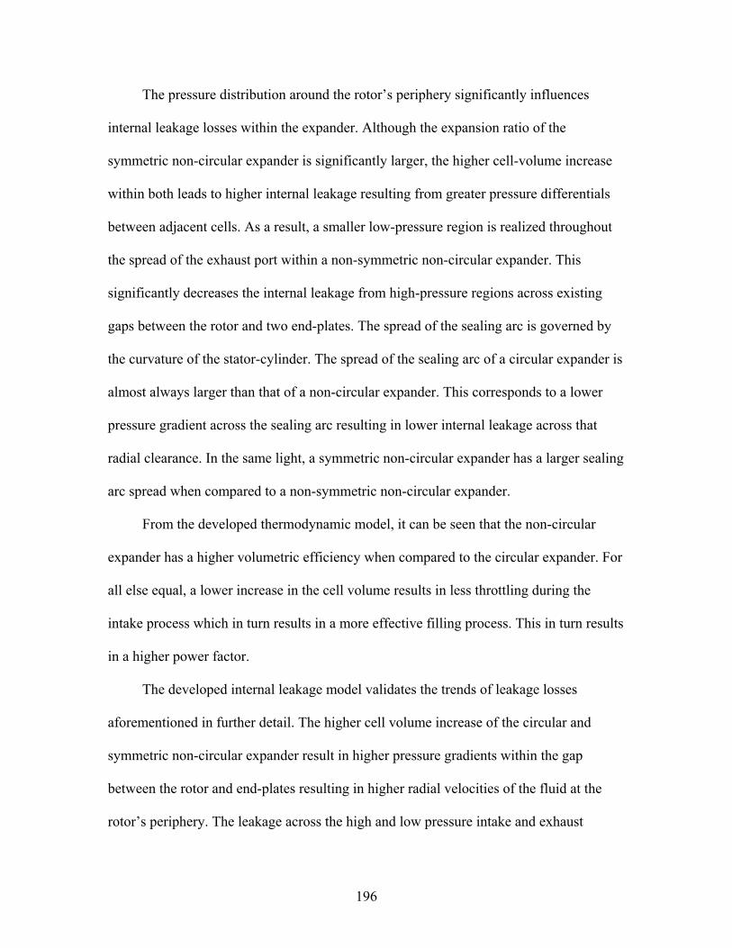
196
The pressure distribution around the rotor’s periphery significantly influences
internal leakage losses within the expander. Although the expansion ratio of the
symmetric non-circular expander is significantly larger, the higher cell-volume increase
within both leads to higher internal leakage resulting from greater pressure differentials
between adjacent cells. As a result, a smaller low-pressure region is realized throughout
the spread of the exhaust port within a non-symmetric non-circular expander. This
significantly decreases the internal leakage from high-pressure regions across existing
gaps between the rotor and two end-plates. The spread of the sealing arc is governed by
the curvature of the stator-cylinder. The spread of the sealing arc of a circular expander is
almost always larger than that of a non-circular expander. This corresponds to a lower
pressure gradient across the sealing arc resulting in lower internal leakage across that
radial clearance. In the same light, a symmetric non-circular expander has a larger sealing
arc spread when compared to a non-symmetric non-circular expander.
From the developed thermodynamic model, it can be seen that the non-circular
expander has a higher volumetric efficiency when compared to the circular expander. For
all else equal, a lower increase in the cell volume results in less throttling during the
intake process which in turn results in a more effective filling process. This in turn results
in a higher power factor.
The developed internal leakage model validates the trends of leakage losses
aforementioned in further detail. The higher cell volume increase of the circular and
symmetric non-circular expander result in higher pressure gradients within the gap
between the rotor and end-plates resulting in higher radial velocities of the fluid at the
rotor’s periphery. The leakage across the high and low pressure intake and exhaust

197
regions via the sealing arc also increases as the spread of the sealing arc decreases.
Leakage losses past the vane tips and the sides of the vanes, adjacent to end-plates, of a
multi-vane expander tend to be significant. The magnitude of these losses is governed by
how well the vanes remain in contact with the stator-cylinder by means of under-vane
pressure forces or springs. If all else is similar, the leakage past the vane tips in the
circular expander is greater due to a higher increase in cell-volume and thus a greater
pressure differential between adjacent vanes in the intake process (i.e. smaller angular
displacements). This is a direct result of the larger eccentricity during the intake process
when compared to non-circular expanders. This results in a greater required vane
protrusion, X(θ), from the vane slot. Inadequate under-vane forces will hence result in
larger leakage flow channels. Internal leakage past the vane sides is also a function of the
pressure differential and vane protrusion and the analysis follows in the same light as
mentioned previously.
Although the symmetric non-circular and circular expanders exhibit approximately
similar working fluid capacities, the internal leakage losses in the former are much more
significant. This is a result of the larger vane protrusions necessary to maintain vane and
stator-cylinder contact. It is also the result of higher-pressure differences between
adjacent cells. Although the circular expander exhibits larger leakage losses when
compared to the non-symmetric, non-circular expander (see above) it’s higher capacity
(amount of mass in control volume at cut-off angle) leads to a smaller leakage coefficient
(ratio of mass flow of leakage to total mass flow through expander) and hence higher
leakage efficiency.

198
The kinematic and friction models developed aid in further performance prediction
and comparison between circular and non-circular multi-vane expanders. The number of
arcs that describe the geometry of the stator-cylinder greatly affect the sliding velocity
and acceleration of the vanes. Since the non-circular stator is described by at least 5 arcs,
there are an increased number of discontinuities and an increased rate of change in vane
sliding acceleration and velocity respectively (Figure 5-22). At larger eccentricities, the
presence of these characteristics results in larger frictional losses. For example the
circular expander would exhibit larger frictional losses during the intake and latter stages
of the exhaust processes due to a larger eccentricity. Due to the higher fluid handling
capacity of the circular expander, and hence power output, the mechanical efficiency of
this device is typically larger than that of a non-circular expanders although higher
frictional losses may be realized.
The choice of stator-cylinder geometry is an open-ended design optimization
problem. Fluid handling and geometric volume ratio requirements as well as physical
constraints when modifying existing machinery also influence this choice. Trade-offs due
to competing effects arising from frictional losses and internal leakage losses are also
expected.
Heat Transfer
The following conclusions were made regarding heat transfer modeling:
• External insulation is deemed necessary • Order of magnitude analysis reveal insignificance relative to other loss mechanisms • Moderate temperature differences • Time available for heat transfer to/from working fluid in control volume is insufficient

199
Figure 5-1. Schematic of nomenclature used and leakage paths of a circular rotary-vane expander with general orientation and a (a) conventional or (b) modified intake ports
Sealing arc
Trailing vane STATOR
Leading vane
ROTOR
θin
θ
θex
δ
ω
OS
OR ψ
e rR
V2
V1
(6)
(5)
(3)
(4)
(2)
(1)
(b)
rS
(a)
θseal
RS(θ)
rm
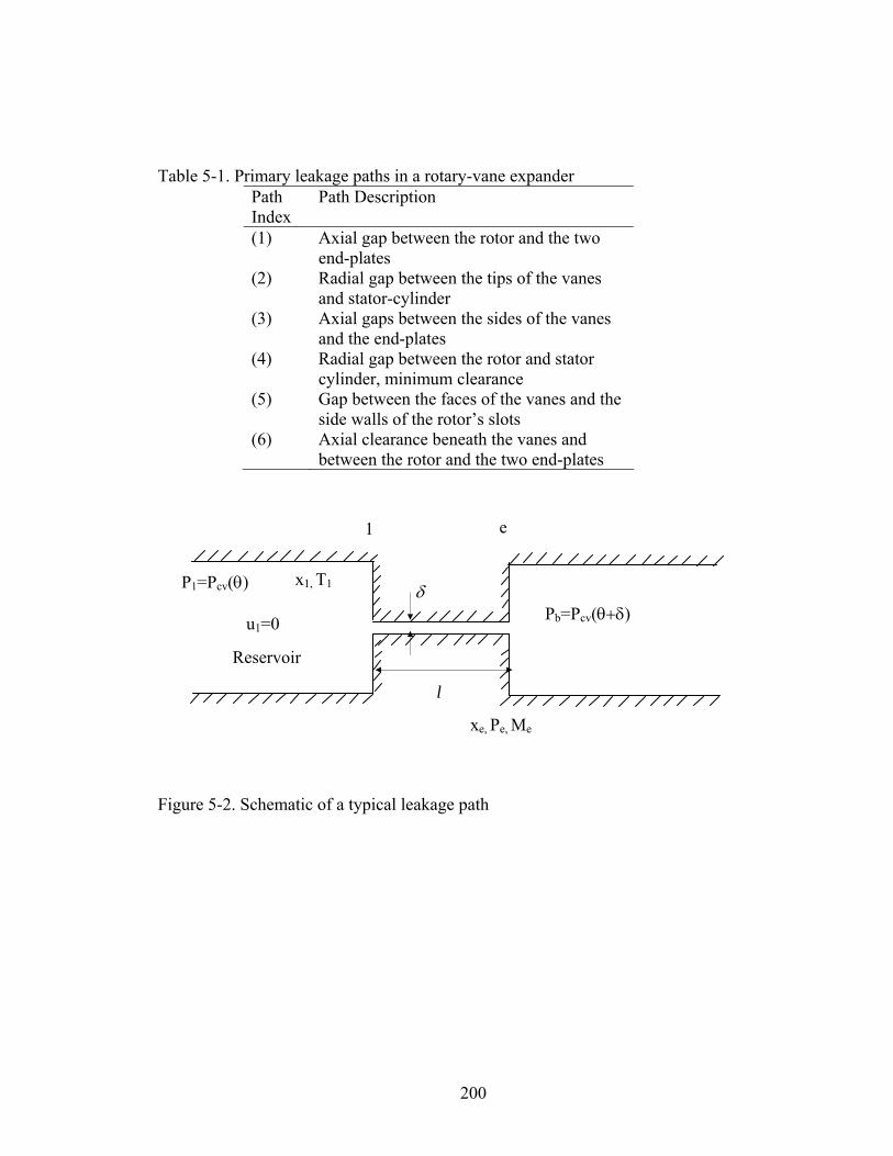
200
Table 5-1. Primary leakage paths in a rotary-vane expander
Path Index
Path Description
(1) Axial gap between the rotor and the two end-plates
(2) Radial gap between the tips of the vanes and stator-cylinder
(3) Axial gaps between the sides of the vanes and the end-plates
(4) Radial gap between the rotor and stator cylinder, minimum clearance
(5) Gap between the faces of the vanes and the side walls of the rotor’s slots
(6) Axial clearance beneath the vanes and between the rotor and the two end-plates
Figure 5-2. Schematic of a typical leakage path
1 e
Reservoir
P1=Pcv(θ)
u1=0 Pb=Pcv(θ+δ)
x1, T1
xe, Pe, Me
l
δ
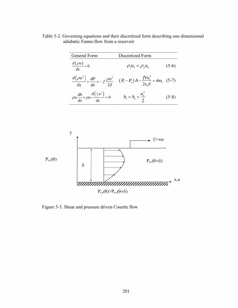
201
Table 5-2. Governing equations and their discretized form describing one-dimensional
adiabatic Fanno-flow from a reservoir
Figure 5-3. Shear and pressure driven Couette flow
General Form Discretized Form ( ) 0
d udxρ
= 1 1 e eu uρ ρ= (5-6)
( )2 2
2d u dP uf
dx dxρ ρ
δ+ = − ( )
2
1 2e
e ee
fVuP P A muv δ
− − = & (5-7)
( )212 0
d udhu udx dx
ρ ρ+ = 2
1 2e
euh h= + (5-8)
y
Pcv(θ) δ
Pcv(θ+δ)
Pcv(θ)>Pcv(θ+δ)
U=ωr
x,u

202
Table 5-3. Variation of operational and dimensionless parameters to model flow in axial gap as laminar and with a zeroth-order approximation
Operational Parameters Dimensionless Parameters
Condition
35<Tin<55oC 110<Eu<80x103 EuReδ1>1, Eu>20 0<x<0.25 4x10⁴<Reδ1S2<2x10⁵ Reδ1S2<105, Laminar 100<Ω<1000 RPM 0.04<Reδ1<1.93 Reδ1<1 25<δ1<65μm 394<S<984 S>>1
1000
1200
1400
1600
1800
2000
0 100 200 300
Angular Displacement, θ
Pre
ssur
e, k
Pa
Actual
8 terms
24 terms
Linear Approx.
Figure 5-4. Non-axisymmetric pressure boundary condition on outer surface of the rotor

203
Figure 5-5. Free-body diagram of a vane protruding outward from a rotor slot at a local angle θ
ω
FPL
FPR
Fn
Ft=μsFn
O
mvg θ
FR
FL
Fb
Fc
Fa
μLFL
μRFR X(θ)
Hv/2
tv=ts
X(θ)/2
Hv

204
050
100150200250300350
0 45 90 135 180 225 270 315 360
Angular Displacement, θ
Rea
ctio
n Fo
rces
, N
FLFRFN
Figure 5-6. Schematic of generalized Couette flow in the axial gap between rotor and end-plate
Figure 5-7. Variation of reaction forces on a vane with no vane-tip curvature as a function of angular displacement
End-Plate
r , u
Rotor
z
rR
βrR 0inP Pdr−
<
Pin
P
δ
U

205
-50
0
50
100
150
0 45 90 135 180 225 270 315 360
Angular Displacement, θ
Rea
ctio
n Fo
rces
, N FNFLFR
Figure 5-8. Variation of reaction forces on a vane with a circular vane-tip profile as a
function of angular displacement
Figure 5-9. Variation of leakage from/to the expander cavity as a function of angular displacement due to non-axisymmetric flow between the rotor and stationary end-plates for different intake angle spreads
-0.8-0.6
-0.4
-0.20
0.2
0.4
0.6
0 100 200 300 400
Angular Displacement, θ
Leak
age
Mas
s Fl
ow, k
g/s
th,in=60 deg
th,in=15 deg
th,in=5 deg

206
Figure 5-10. Variation of non-axisymmetric leakage from/to the expander cavity for the ideal and throttling cases
Figure 5-11. Variation of leakage from/to the expander cavity through the gap between the sides of the vanes and end-plates for different intake angle spreads
-0.5-0.4-0.3-0.2
-0.10
0.10.2
0 100 200 300
Angular Displacement, θ
Leak
age
Mas
s Fl
ow k
g/s
Throttling th,in=60
Ideal
Throttling th,in=30
-0.015
-0.01
-0.005
0
0.005
0.01
0.015
0 100 200 300
Angular Displacement, θ
Leak
age
Mas
s Fl
ow, k
g/s
th,in=60
th,in=15
th,in=5

207
0.0E+00
2.0E-04
4.0E-04
6.0E-04
8.0E-04
1.0E-03
1.2E-03
0 5 10 15 20 25 30 35
Angular Displacement, θ
Mas
s Fl
ow R
ate
mlk
,5, k
g/s
0.00.51.01.52.02.53.03.5
0 100 200 300 400 500 600 700 800 900 1000
Expander Rotational Speed, RPM
Expa
nder
Mas
s Fl
ow R
ate
kg/s
IdealActual
Figure 5-12. Variation of leakage to the expander cavity from the rotor slot (modified
intake) through the gap between the face of the vanes and rotor slot
Figure 5-13. Variation of the ideal and actual mass flow-rates through the expander as a function of rotational speed

208
0.00.51.01.5
2.02.53.03.5
4 6 8 10 12
Number of Vanes
Expa
nder
Mas
s Fl
ow R
ate
kg/s Ideal
Actual
Figure 5-14. Variation of the ideal and actual mass flow-rates through the expander as a function of the number of vanes
Figure 5-15. Comparison of way by which fluid is introduced into the expander’s cavity; A) conventional intake via intake port and B) modified intake via rotor slots through end-plates to ensure vane-tip and stator-cylinder contact
A B
θinω
θin
ω

209
Figure 5-16. Flow through a sudden contraction
Table 5-4. Comparisons of contraction coefficients for turbulent single-phase flow 1/σ 0 0.2 0.4 0.6 0.8 1 Cc Perry [1] 0.586 0.598 0.625 0.686 0.79 1 Cc Ruffell [2] 0.618 0.637 0.664 0.708 0.790 1.0 % 5.2 6.1 5.9 3.1 0.0 0.0
1 21
c21
fully developed inlet flow
fully developed outlet flow
transitional region
recirculation

210
T
L
θinωθin
ω
L
T
θinω
L T
I II ΔV2 ΔV1
III
Figure 5-17. Schematic of the three phases of vane orientation that occur during the intake process

211
0200400600800
100012001400160018002000
0 100 200 300
Angular Displacement, deg
Pres
sure
, kPa
Throttling
Ideal
θin+δ
Figure 5-18. Variation of pressure in expander cavity as a function of angular displacement for the ideal and actual (throttling only) cases
Table 5-5. Variation of volumetric efficiency and final pressure as a function on inlet
angle in an expander with throttling losses accounted for No Throttling With Throttling
θin rv Pex, kPa ηv,% Pex, kPa ηv,% ΔP 5 8.704 681.48 100 432.39 52.92% -35.09%
15 5.762 878.52 100 618.86 57.31% 5.62% 25 4.134 1049.29 100 795.70 59.98% 26.59% 35 3.138 1194.38 100 955.93 63.44% 38.90% 45 2.487 1315.36 100 1096.45 65.79% 46.73% 75 1.496 1562.02 100 1402.39 71.42% 58.35%
Tevap=5oC, Tcond=45oC, rv,process=10.925, Nv=8, Pex, kPa=584.1

212
Figure 5-19. Schematic of the intake port of the modified rotary-vane intake through the end-plates and into the rotor cavity via rotor slots
Figure 5-20. Schematic of (a) symmetric (b) non-symmetric non-circular rotary-vane expander comprised of four circular arcs (1-4) and a sealing arc (5)
1 2
3*
4
5
Contraction
Bend
Enlargement
Exit
θin θin
(a) (b)

213
0
2
4
6
8
10
12
14
0 20 40 60 80 100 120 140 160 180 200 220 240 260 280 300 320 340 360
Angular Displacement, deg
Vane
Dis
plac
emen
t, m
mCircular MVENon-circular MVE
Figure 5-21. Variation of vane displacement as function of the leading vanes’ angular displacement for both a circular and non-circular MVE
-4
-3
-2
-1
0
1
2
0 20 40 60 80 100 120 140 160 180 200 220 240 260 280 300 320 340 360
Angular Displacement, deg
Vane
Vel
ocity
, m/s
Circular MVENon-circular MVE
Figure 5-22. Variation of vane velocity as function of the leading vanes’ angular displacement for both a circular and non-circular rotary-vane expander
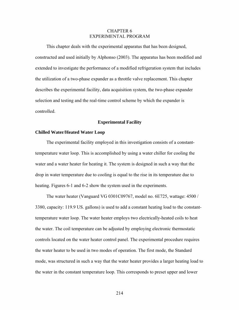
214
CHAPTER 6 EXPERIMENTAL PROGRAM
This chapter deals with the experimental apparatus that has been designed,
constructed and used initially by Alphonso (2003). The apparatus has been modified and
extended to investigate the performance of a modified refrigeration system that includes
the utilization of a two-phase expander as a throttle valve replacement. This chapter
describes the experimental facility, data acquisition system, the two-phase expander
selection and testing and the real-time control scheme by which the expander is
controlled.
Experimental Facility
Chilled Water/Heated Water Loop
The experimental facility employed in this investigation consists of a constant-
temperature water loop. This is accomplished by using a water chiller for cooling the
water and a water heater for heating it. The system is designed in such a way that the
drop in water temperature due to cooling is equal to the rise in its temperature due to
heating. Figures 6-1 and 6-2 show the system used in the experiments.
The water heater (Vanguard VG 0301C09767, model no. 6E725, wattage: 4500 /
3380, capacity: 119.9 US. gallons) is used to add a constant heating load to the constant-
temperature water loop. The water heater employs two electrically-heated coils to heat
the water. The coil temperature can be adjusted by employing electronic thermostatic
controls located on the water heater control panel. The experimental procedure requires
the water heater to be used in two modes of operation. The first mode, the Standard
mode, was structured in such a way that the water heater provides a larger heating load to
the water in the constant temperature loop. This corresponds to preset upper and lower
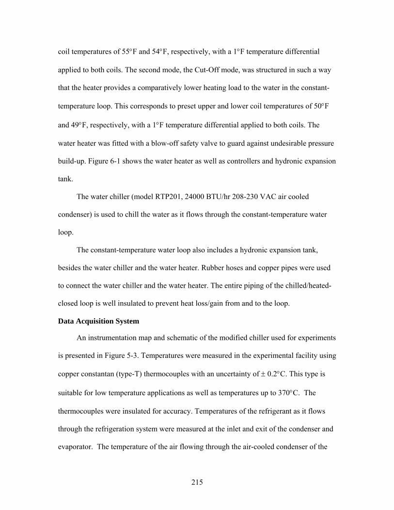
215
coil temperatures of 55°F and 54°F, respectively, with a 1°F temperature differential
applied to both coils. The second mode, the Cut-Off mode, was structured in such a way
that the heater provides a comparatively lower heating load to the water in the constant-
temperature loop. This corresponds to preset upper and lower coil temperatures of 50°F
and 49°F, respectively, with a 1°F temperature differential applied to both coils. The
water heater was fitted with a blow-off safety valve to guard against undesirable pressure
build-up. Figure 6-1 shows the water heater as well as controllers and hydronic expansion
tank.
The water chiller (model RTP201, 24000 BTU/hr 208-230 VAC air cooled
condenser) is used to chill the water as it flows through the constant-temperature water
loop.
The constant-temperature water loop also includes a hydronic expansion tank,
besides the water chiller and the water heater. Rubber hoses and copper pipes were used
to connect the water chiller and the water heater. The entire piping of the chilled/heated-
closed loop is well insulated to prevent heat loss/gain from and to the loop.
Data Acquisition System
An instrumentation map and schematic of the modified chiller used for experiments
is presented in Figure 5-3. Temperatures were measured in the experimental facility using
copper constantan (type-T) thermocouples with an uncertainty of ± 0.2°C. This type is
suitable for low temperature applications as well as temperatures up to 370°C. The
thermocouples were insulated for accuracy. Temperatures of the refrigerant as it flows
through the refrigeration system were measured at the inlet and exit of the condenser and
evaporator. The temperature of the air flowing through the air-cooled condenser of the

216
water chiller was also measured. In the constant-temperature water loop, the temperature
of the water was measured at the inlet and exit of the water chiller tank and at the outlet
of the pump.
Pressure transducers (Mamac Systems, model no. PR-264, accuracy ±1% of the full
scale) were used to measure the pressure of the refrigerant at five locations in the
refrigeration system. These transducers were calibrated to give an output of 0-5 VDC to
the data acquisition board corresponding linearly to a pressure range of 0-2000 kPa. The
transducers were calibrated using a Calpal hand held pressure calibrator. These
transducers were used to measure the refrigerant pressure at the inlet and outlet of the
condenser and evaporator.
Air humidity at the inlet and exit of the air-cooled condenser was measured using a
humidity transducer (Mamac Systems, model no. HU-225, accuracy ±3% of the full
scale). The transducers were calibrated to give an output of 0-5 VDC to the data
acquisition board corresponding linearly to a relative humidity range of 0-100%.
The refrigerant mass flow-rate as it flows through the chiller was measured using a
flow-rate transducer (Sponsler Co., Inc., model no. SP711-3). This transducer was
calibrated to give an output of 0-5 VDC to the data acquisition system corresponding
linearly to a flow-rate range of 0- 47.4293 lbm/min. The water loop mass flow-rate was
measured using a flow-rate indicator (Sponsler Co., Inc., model no. SP3/4-CB-PHL-A-
4X). The water flow-rate was read off the digital display of the transducer.
Compressor power was measured employing the voltage and current transducers
across the compressor motor. The voltage was measured using a voltage transducer
(Flex-Core, model no. AVT-300CX5, accuracy ±0.25%), which was calibrated to give an
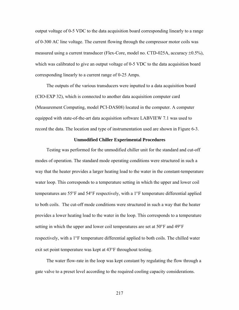
217
output voltage of 0-5 VDC to the data acquisition board corresponding linearly to a range
of 0-300 AC line voltage. The current flowing through the compressor motor coils was
measured using a current transducer (Flex-Core, model no. CTD-025A, accuracy ±0.5%),
which was calibrated to give an output voltage of 0-5 VDC to the data acquisition board
corresponding linearly to a current range of 0-25 Amps.
The outputs of the various transducers were inputted to a data acquisition board
(CIO-EXP 32), which is connected to another data acquisition computer card
(Measurement Computing, model PCI-DAS08) located in the computer. A computer
equipped with state-of-the-art data acquisition software LABVIEW 7.1 was used to
record the data. The location and type of instrumentation used are shown in Figure 6-3.
Unmodified Chiller Experimental Procedures
Testing was performed for the unmodified chiller unit for the standard and cut-off
modes of operation. The standard mode operating conditions were structured in such a
way that the heater provides a larger heating load to the water in the constant-temperature
water loop. This corresponds to a temperature setting in which the upper and lower coil
temperatures are 55°F and 54°F respectively, with a 1°F temperature differential applied
to both coils. The cut-off mode conditions were structured in such a way that the heater
provides a lower heating load to the water in the loop. This corresponds to a temperature
setting in which the upper and lower coil temperatures are set at 50°F and 49°F
respectively, with a 1°F temperature differential applied to both coils. The chilled water
exit set point temperature was kept at 43°F throughout testing.
The water flow-rate in the loop was kept constant by regulating the flow through a
gate valve to a preset level according to the required cooling capacity considerations.
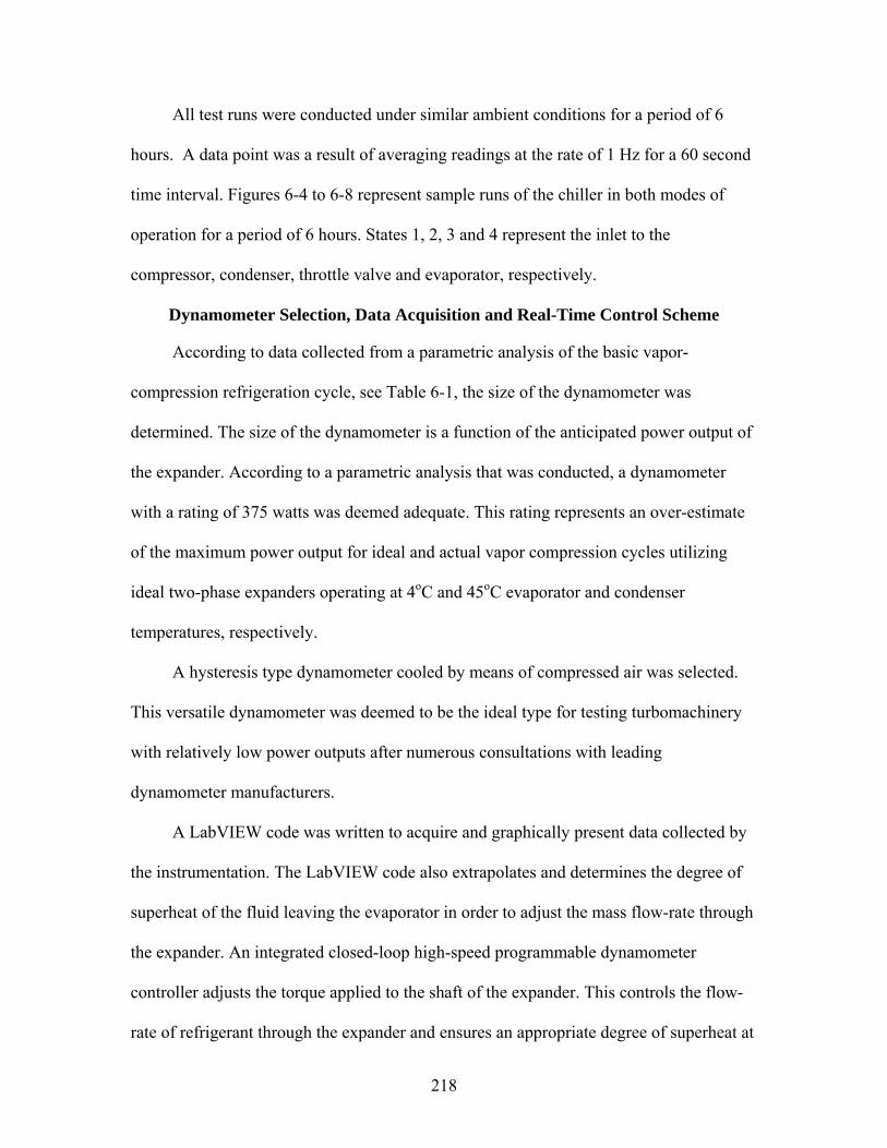
218
All test runs were conducted under similar ambient conditions for a period of 6
hours. A data point was a result of averaging readings at the rate of 1 Hz for a 60 second
time interval. Figures 6-4 to 6-8 represent sample runs of the chiller in both modes of
operation for a period of 6 hours. States 1, 2, 3 and 4 represent the inlet to the
compressor, condenser, throttle valve and evaporator, respectively.
Dynamometer Selection, Data Acquisition and Real-Time Control Scheme
According to data collected from a parametric analysis of the basic vapor-
compression refrigeration cycle, see Table 6-1, the size of the dynamometer was
determined. The size of the dynamometer is a function of the anticipated power output of
the expander. According to a parametric analysis that was conducted, a dynamometer
with a rating of 375 watts was deemed adequate. This rating represents an over-estimate
of the maximum power output for ideal and actual vapor compression cycles utilizing
ideal two-phase expanders operating at 4oC and 45oC evaporator and condenser
temperatures, respectively.
A hysteresis type dynamometer cooled by means of compressed air was selected.
This versatile dynamometer was deemed to be the ideal type for testing turbomachinery
with relatively low power outputs after numerous consultations with leading
dynamometer manufacturers.
A LabVIEW code was written to acquire and graphically present data collected by
the instrumentation. The LabVIEW code also extrapolates and determines the degree of
superheat of the fluid leaving the evaporator in order to adjust the mass flow-rate through
the expander. An integrated closed-loop high-speed programmable dynamometer
controller adjusts the torque applied to the shaft of the expander. This controls the flow-
rate of refrigerant through the expander and ensures an appropriate degree of superheat at

219
the compressor suction. Figure 6-9 shows a schematic of the proposed control system and
algorithm.
In order to determine the corresponding saturation temperature at a given
evaporator outlet pressure, the following equation proposed by Baehr and Tillner-Roth
(1995) was solved iteratively using the Newton-Raphson method. Equation (6-1) can be
used for both R-22 and R-134a with the appropriate constants in Table 6-2
31 2 41 2 3 4
( ) 1ln1
nn n n
c
P a a a aPθ θ θ θ θ
θ⎛ ⎞
⎡ ⎤= + + +⎜ ⎟ ⎣ ⎦−⎝ ⎠ (6-1)
where
Pc = Critical Pressure of the Refrigerant
θ = Dimensionless Temperature, 1c
TT
θ = −
Tc = Critical Temperature of the Refrigerant
and the coefficients can be found from Table 6-2.
The solution procedure to determine the degree of superheat can be described as
follows:
• Express Equation (6-1) in the form ( , ) 0f Pθ = .
• Input the Pressure, P(θ), into Equation (6-1) at which the corresponding saturation temperature is desired.
• Input an initial guess as to what that saturation temperature is and calculate the corresponding dimensionless temperature, θο.
• Compute the Derivative of Equation (6-1) with respect to the dimensionless
temperature, ( , )odf Pdθθ
, and use the Newton-Raphson method to find a new
estimated value for θ, ( , )( , )
oo
o
f Pf P
θθ θθ
= −′
.
220
• Continue process until convergence.
Rotary-vane Expander Selection
This section details the different choices of rotary-vane type turbomachinery that
have been modified and used as two-phase expanders.
Modified Automotive Air-conditioning Compressor
A double-acting rotary-vane automotive A/C compressor of unknown capacity at
the time of purchase due to proprietary restrictions was obtained. The automotive
compressor was deemed appropriate after several unsuccessful attempts of contacting
compressor manufacturers for residential and industrial refrigeration systems.
Automotive compressors are typically designed for volatile working conditions and may
be difficult to modify. Modifications to the piping to/from the compressor housing could
also be difficult to modify. Rotary-vane compressors were used extensively in the late
80s and early 90s by automobile manufacturers such as BMW and Mazda.
The rotary-vane compressor selected and purchased is a re-built A/C compressor
that runs on R-12 and can be retrofitted to work with R-22 and R-134a. After conducting
research dealing with the modifications that must be done in order to operate it as an
expander, the modifications deemed necessary included changing fittings, O-rings, and
the reed valve.
Internal leakage losses associated with this modified A/C compressor were initially
thought to be less than leakage losses associated with other type of modified
turbomachinery due to the typical existence of tight tolerances and need for significantly
efficient compressor designs.
221
Performance of Modified Compressor
Upon operation of the modified system with the expander installed, the expander
was found to perform unexpectedly. Further examination of the internals of the expander
revealed that sealing problems associated with the deformation of two O-rings may have
been the cause. These O-rings seal the high and low pressure pockets within the
compressor/expander (Figure 6-10). Observation of the O-rings, upon completion of
several tests in the refrigeration system, showed signs of elastic deformation. Tests with
compressed air were conducted after which it was determined that the inadequate sealing
provided by the O-rings may not be the only cause of the unfavorable performance of the
expander. Problems associated with the start-up operation (as defined below) of this
expander were then investigated.
It was found after further examination and testing of the internal cavity of the
expander that significant centrifugal force due to rotation is necessary to maintain
continuous contact between the vane-tips and the stator-cylinder. Although pressurizing
slots and a means for pressurized fluid to enter the slots exist for compressor operation,
there is no guarantee that the high pressure fluid enters the pressurizing slots when run as
an expander. This lack of contact is believed to be the primary cause of the expander’s
poor performance since insufficient vane protrusion would hinder the development of
adequate torque from the incoming working fluid acting on the vanes. To overcome this,
a mechanically driven coupling was used to drive the expander shaft to generate
sufficient centrifugal force and help eliminate any start-up issues. Secondly, prototype
mechanical springs, in the form of leaf springs, were designed and machined out of
tempered spring steel and tested in the vane slots. Leaf springs were determined to be the
most suitable type of spring for this application because of both the dynamics of the

222
application and the dimensions associated with the vane slots. Three different
configurations of the vanes were machined in order to determine the optimum vane
geometry to ensure vane-stator contact with the help of leaf springs placed in the
pressurizing slots. Upon installation in the expander initial testing revealed that the
modified vanes did very little to enhance the performance of the expander although
continuous contact between the vane-tips and stator-cylinder was maintained.
One possibility the expander did not function as expected is the internal flow path
arrangement (Figure 6-11). Since the current expander was initially designed as an
automotive air-conditioning compressor, the dual flow path configuration of the
compressor is not ideal for expansion. Upon testing the expander with refrigerant, the
shaft of the expander would operate as if the shaft were locked. This resistance to motion
was deemed to be the primary result of the compression of liquid due to poor geometrical
design of the intake or exhaust ports. Further analysis of the symmetric, elliptical double-
acting rotary-vane compressor revealed that the minimum tolerances that exist between
the rotor and elliptical stator-cylinder were approximately 25 μm (0.001”). The
temperature differential between the intake (high side temperature) and the exhaust
(evaporator temperature) may have also caused the rotor to lock due to material thermal
expansion of either the stator-cylinder or rotor. Further experimental measurements are
needed to prove this. This also supports the conclusion that an alternate flow path was
needed to eliminate any unwanted liquid compression and material thermal expansion
that may take place. An alternate flow path configuration would also eliminate the
extremely “tight” tolerances that exist between the rotor and the stator-cylinder at the
minimum clearance.

223
Design Issues
Several design issues were deemed responsible for the inadequate operation of this
modified double acting compressor. They include the following:
• Unsuitable volume ratio as determined from a modified geometrical code.
• Intake port spread of θin=10o. This results in significant throttling losses in the intake port. This compressor exhaust port is a sound design choice.
• Overlap between intake and exhaust ports. Since the compressor has 5 vanes (δ=72o) there exists an approximate 65o overlap (accounting for vane thickness) that is responsible for excessive leakage past the minimum clearance on either side of the rotor. A significant driving potential drives this.
• Minimal clearance is 25 μm. Significant pressure and temperature differentials on either side of the minimal clearance cause thermal expansion of the materials that results in the “locking” of the expander shaft.
• Poor design of exhaust port as an expander. Retrofitting the ports is difficult due to the hermetic nature of the compressor.
Designed and Machined Expander
The design, fabrication and testing of a machined rotary-vane expander was
deemed to be the next most reliable and suitable alternative. It would also aid in
understanding the complex factors involved in selecting geometric design choices for this
specific application. Many factors were taken into consideration when making this
decision and they included:
• The ability to design the rotor and stator-cylinder. During this process the
geometric volume ratio of the expander would be optimized to allow for complete expansion of the refrigerant and to avoid under- and over-expansion. The dimensions of the cylinders are constrained by the dimensions of the dynamometer.
• The ability to design the flow path of the refrigerant. This would ensure proper expansion of the refrigerant and avoid compression and additional pressure losses which may result from poor flow path design. These inefficiencies would reduce the amount of power that may be recovered from the system expansion process by means of an expander.

224
• The ability to optimize the location and the spread angles of the intake and exhaust ports. This provides an additional degree of flexibility when optimizing the geometric volume ratio of the expander.
• Ease of installing instrumentation. Locations for different measuring devices, primarily pressure taps and thermocouples, would be taken into consideration. This would allow for a more extensive comparison of theoretical and experimental results.
• Both the size and the weight of the expander may be optimized.
• The ability to design and fabricate the vanes. The design would account for the addition of mechanical springs if needed. These springs would keep the vane-tips in continuous contact with the stator-cylinder. Either compression or leaf type springs may be utilized with appropriate modifications to the vanes and rotor-slots made.
In order to ensure the adequate design of a rotary-vane expander, the geometric
volume ratio of the expander must be as close as possible, ideally (see Chapter 5 in
regards to over- and under-expansion), to the process volume ratio. Adequate selection of
the expander’s dimensions ensures an appropriate value of the expander’s geometric
volume ratio suitable for the use of this rotary-vane expander as a throttle valve
replacement in vapor compression refrigeration systems. Other primary variables that
will play a critical role in the performance of this expander include the intake port arc
length and width, the exhaust port location, depth, and contour, the number of vanes and
the aspect ratio of the rotor. Other variables that effect the design of the expander and can
lead to poor performance of the expander include bearing design and location, rotor
dynamics and the method by which the vanes will maintain continuous contact with the
stator-cylinder. All of the aforementioned design variables have been addressed
thoroughly and a preliminary designs of the expander was developed with the aid of
recent literature and commercially available rotary-vane type turbomachinery.
Adequate tolerances between the various moving parts were allotted to ensure
proper lubrication and a reduction in internal leakage and frictional losses. The tolerances

225
were calculated to ensure that internal leakage losses are minimized. Springs were
preliminary deemed to be unnecessary due to adequate centrifugal forces that are
expected in this new design. Generated centrifugal forces are needed to maintain
continuous contact between the vane-tips and the stator-cylinder.
Sizing, selection and the mounting locations of two bearings were also carried out.
Conventional shielded ball bearings were selected since they are inexpensive and are
rated for at least 1,000 lbs in both the radial and axial directions. According to
preliminary estimates of the forces that are expected the rating aforementioned should
suffice.
Initial performance tests performed with compressed air and refrigerant revealed
that leaks from the shaft penetration were still significant. The original dimension of the
end-plate (shaft side) was modified and a sealing disc was designed to be bolted to the
end-plate. The sealing mechanism that was conceived for this application consisted of a
tapered sealing disc that would be bolted to the modified end-plate. The gaps that exist
between the tapered disk and the shaft are sealed with general purpose Teflon
compression packing. Further performance testing showed a significant decrease in the
amount of refrigerant/air that leaks.
Performance of Machined Expander
Further testing with compressed air revealed that there exists a critical pressure
differential between the inlet and exhaust states required to overcome the inertial mass of
the expander and vanes and any starting friction between any of the sliding or moving
parts.
During testing of the newly designed expander in the refrigeration system, it was
apparent that the shaft of the expander didn’t lock as was the case with the first expander

226
tested. However, the newly designed expander didn’t function as desired due to
significant external leakage. This would deem experiments unrepeatable and cause
excessive uncontrolled refrigerant leakage to the ambient. The design of the expander
was modified to eliminate leakage losses that are primarily due to imperfections in the
current rotary-shaft seal design. Additional research and possible design/selection of
commercially available rotary shaft seals was deemed necessary but beyond the scope of
this investigation. Other factors that may cause this undesirable performance is the fact
that the expander’s internal size and weight (sliding and moving parts) play critical
factors in effecting the value of the critical pressure difference necessary to start the
expander.
The performance characteristics of interest for the two-ton air-cooled chiller used
as the basis for this experimental program are limited. These parameters include, but are
not limited to, the mass flow-rate of the refrigerant, the pressure differential between the
high-side and low-side and the thermodynamic state properties at the exit state of the
condenser. The parametrical relationship that must be satisfied in order for the expander
to operate is that the expander displacement must match the experimental volumetric
flow-rate of the refrigerant in the refrigeration system.
Modified Air-Motor
A properly sized, 4-vane, circular GAST air-motor was then tested as an expander.
The inlet ports are engineered in such a way that adequate under-vane pressure from the
incoming refrigerant helps provide for continuous contact between the vane-tips and
stator-cylinder. This also eliminates severe throttling losses that may arise due to a short
inlet port spread. This is typically the case in conventional expanders, where the fluid is
introduced directly into the expander’s cavity. As mentioned previously, the inlet port

227
spread is among the most influential geometrical design choices which affect the
geometric volume ratio of a rotary-vane expander.
The geometrical characteristics of this unmodified expander were found to be
unsuitable for the purpose of its use as an expansion device. Table 6-3, shows 12
proposed modifications, a majority of which have already been machined, in order to
optimize the geometric volume ratio of the expander. Several constraints, namely the
vane height, maximum protrusion from the vane slot, machining complexity and
mechanical strength have been addressed to yield parametrically optimized design
parameters using the models developed to yield a maximum volume ratio.
It should be noted that the inlet start parameter denotes the angular location relative
to the datum at which the intake process begins. In conventional designs, and previous
work, this was 0o. In this design, the intake process begins at 55o. It should also be noted
that the angular locations of the cut-off (minimum) volume V1 and the exhaust
(maximum) volume V2 are also presented. The angular location of the cut-off volume is
the sum of the inlet start location, angle between successive vanes δ and spread of the
inlet port θin. The angular location of the exhaust volume is a design parameter that
typically corresponds to the location of maximum volume. The ratio of the maximum to
minimum volume is defined as the geometric volume ratio.
It can be seen that the unmodified circular expander’s geometric volume ratio is
unity due to a very large inlet port spread (θin=90o) and 4 vanes (δ=90o). It has been
previously shown that the geometric volume ratio increases as the number of vanes
increase. Four additional vane slots were machined into the rotor as well as the angular
holes that supplied the incoming fluid into the expander’s cavity. This modification

228
alone had a detrimental effect on the volume ratio since the location of the exhaust port in
a circular expander is 180o. Hence the unmodified expander’s exhaust port begins in the
region of compression that follows the angular location of maximum volume. It can be
seen that the geometric volume ratio of the circular expander increases as the inlet port
spread is decreased (case 2) and the location of the exhaust port is changed (case 3).
Further reduction in the intake port spread (case 4) leads to an increase in volume ratio,
but ultimately the extremely small eccentricity that exists between the rotor and stator-
cylinders limits the amount of expansion that can be achieved. It should also be noted that
only 15% of the vanes’ total height protruded from the vanes’ slot. It was found that the
complexity of machining modified end-plates and reducing the size of the rotor made
machining a non-circular stator cylinder very attractive. These alternate designs can be
seen in Figure 6-12.
Case 5 represents the first use of a machined symmetric non-circular stator-
cylinder. Optimized geometrical parameters from earlier test cases were used. For the
symmetric non-circular case, the maximum expansion volume occurs at the angular
location of 220o (180o). It should be noted that the values listed in Table 6-3 correspond
to a generally oriented circular expander, the basis of the design code developed. The
extent that the stator-cylinder could be machined was constrained by an adequate sealing
thickness as well as the minimum vane height in the rotor slot necessary to maintain
adequate operation of the expander. This percentage was found to be approximately 20%.
By comparing cases 5, 6, 7, 8 and 9, it was observed that the angular location of the
intake port start has a tremendous impact on the geometric volume ratio of the expander.
This arises due to the fact that the angular location of the cut-off volume decreases as the
229
location of the start of the intake port decreases. The current design introduces the fluid
into the expander cavity via a 25o angular cut in the rotor. This requires the intake port
start to be no less that 25o. This ensures that the fluid is not introduced into the minimum
volume encountered during the sealing arc spread or directly into the exhaust port.
Further increase in the geometric volume ratio can only be attained if a non-
symmetric non-circular stator-cylinder is used. The maximum geometric volume ratio
obtained is 7.3 (case 12) whereas it is 3.86 (case 7) for the symmetric non-circular
expander. The rate of increase of the volume in a non-symmetric non-circular expander is
substantially less than that corresponding to the symmetric non-circular expander and
hence a larger geometric volume ratio can be achieved.
Single-Phase Experiments
In this section the objectives, experimental set-up and results of the single-phase
tests that have been conducted are described. The objectives of these experiments
included the verification of the feasibility of using rotary-vane turbomachinery, air-
motors and compressors, as expanders. In order to do so, the thermodynamic and fluid
mechanic characteristics of both the rotary-vane air-motors, compressors and expanders
were analyzed. The optimum geometrical and operational characteristics of each machine
are presented. Experiments were conducted to understand the working principles and
operational constraints of each machine. This study also helps formulate design concepts
that can be utilized to modify air-motors or compressors into optimized expanders for
single phase flow applications. The experiments will be used to predict and evaluate
modifications made to geometrical parameters such as the optimum intake and exhaust
port locations, their spreads and the geometric volume ratio as well as resulting
performance parameters such as the work produced, isentropic and volumetric

230
efficiencies. Experimental expertise, including proper assembly and sealing, of rotary-
vane turbomachinery is also expected to be gained and may improve performance and
operation significantly.
Single-phase experiments with compressed air and liquid/vapor R-22 were carried
out on a bench-top experimental set-up with various modifications to a commercially
available rotary-vane air-motor. Dry compressed air supplied to the building is used to
test the device. Saturated vapor or liquid R-22 may also be fed into the expander from a
canister that is in equilibrium. The elevation and orientation of the canister relative to the
expander is important as they determine the state of refrigerant that exits the canister. The
refrigerant used enters the expander from the high pressure supply tank and exits the
expander into an evacuated reclamation tank. Depending on the duration of the test
necessary, the reclamation tank can be maintained at a vacuum pressure maintained by a
vacuum pump. Depending on the geometrical parameters chosen, the device can operate
as an expander. The thickness of the gaskets and rotary-shaft seal design were altered,
when necessary, to accommodate higher working pressures than those recommended by
the manufacturer. The commercially available air-motor is of the non-lubricated type.
The addition of lubrication oil to the working fluid may ensure proper lubrication, sealing
and operation. The inlet and outlet pressures can be adjusted by a pressure regulator and a
valve, respectively. Pressure gauges or transducers, thermocouples, mass flow-rate meter
(rotameter), are installed at the inlet and outlet locations where necessary. The shaft of
the expander is coupled with a hysteresis type dynamometer. The dynamometer is
interfaced with a high speed programmable dynamometer controller which displays the
actual amount of mechanical power extracted, torque produced and rotational speed of

231
the expander. The controller may be interfaced with a computer to provide a continuous
data stream. The controller is operated in the open-loop mode. In this mode the user has
complete control over the braking load, produced by the dynamometer, by which the
torque and speed of the expander are varied. Figure 6-13 shows a schematic of the single-
phase experimental set-up.
In the following sections, the results of numerous tests are summarized. In certain
instances, inadequate operation or complexities are explained.
Summary
A rotary-vane air-motor with an adequate volume displacement has been retrofitted
to an expander by changing the internal geometry of the device, namely the inlet port arc
spread and start, start of exhaust port and the number of vanes. The geometry of the
stator-cylinder is also very critical to the thermodynamic performance of the expander. A
non-circular stator-cylinder has hence been machined. This stator-cylinder is symmetric
about the vertical base line of the expander. The maximum volume ratio that could be
achieved with such a configuration is 5. Further analysis showed that with a non-
symmetric non-circular stator-cylinder, the volume ratio can be increased to
approximately 7.5. In order to avoid time delays that may result from the manufacturer in
case a new air-motor is needed, experimental testing and confirmation is needed before
the non-symmetric, non-circular stator-cylinder is machined.
A major source of problems, external leakage, has been solved. The use of
modified gaskets (both material and thickness) and a modified rotary shaft seal have
ensured adequate sealing of the expander well beyond the rated pressure of 689 kPa.
Additional time and effort has been spent to avoid the manufacture of a costly and heavy
external enclosure. The condenser is expected to operate at a pressure as high as 1.75

232
MPa. Initial tests in isolation with both air and refrigerant have yielded positive results in
regard to the operational speed, sealing and change of state across the expander. The test
set-up could be varied to increase/decrease the operational pressure ratio across the
expander. Start-up problems were also not obvious, in any of the test cases, since
adequate under-vane pressure from incoming refrigerant helps provide for continuous
contact between the vanes and stator-cylinder.
Difficulties arising from the operation of the modified chiller with the expander
installed have hindered the progress of gathering experimental data. These difficulties,
namely, arise from controlling the back pressure (i.e. evaporator pressure) when the
expander loop is opened. The back pressure has a significant effect on the expander
intake and hence the operation of the expander. A low range (0-827 kPa) pressure
regulator was used downstream of the expander to provide a means for both the control
of the evaporator pressure and adequate operation of the refrigeration system. This also
negates the need for the conventional expansion valve to run in series with the expander.
The regulator doesn’t and cannot, however, directly provide any means of control of the
back pressure. These operational difficulties must be addressed. It is interesting to note
that no previous work can be found in the open literature that discusses any operational
difficulties that may arise.
The chiller’s operational parameters were then varied in order to simulate operating
conditions of interest to the funding agency. These operating parameters are namely
higher condensing temperatures and system mass flow-rates. These parameters were
varied in order to provide measurable experimental data that may be used to validate the
analytical models developed.

233
In order for the rotary-vane expander to exhibit adequate operational
characteristics, a necessary pressure drop is required across the expander. One way of
controlling the pressure drop across the expander is by varying the mass flow-rate of
refrigerant in the system. Assuming that the two-phase flow of refrigerant leaving the
condenser is fully developed and turbulent (and 4DRe 2 10≥ × ) and that the pipe surface
is approximately smooth, the friction factor, pressure drop and mass flow-rate may be
expressed as
1/ 50.184Re−= Df (6-2)
2
2ρ
Δ = Δmup f xD
(6-3)
2
4π
= ρ& mDm u (6-4)
Combining Equations (6-2), (6-3) and (6-4) we find that
9/5~p CmΔ & (6-5)
where C is a constant.
It can be seen that the pressure drop across any device scales approximately to the
second power of the mass flow-rate through that device. Retrofitting the current
experimental set-up with a larger compressor, which would in turn increase the mass
flow-rate, is both cost prohibitive as well as potentially problematic or even catastrophic.
This is a result of increased system pressures and working fluid velocities that the
undersized components and piping may realize.
A more promising alternative is to change certain system parameters that would in
essence alter the back-pressure that the expander exhaust senses. In one particular study
in the literature (Badr et al. 1985), the mass flow-rate of cooling water through the

234
condenser of an Organic Rankine Cycle was varied. The authors claim the ability to vary
the operational pressure ratio from approximately 2.2 < Pin/Pex < 4.3. The magnitude of
change of the cooling water mass flow-rate through the condenser has not been reported.
In a similar manner, a reduction of the back-pressure in a vapor-compression
refrigeration cycle could be achieved by varying the mass flow-rate of hot water through
the evaporator. Initial tests with the experimental rig used have validated the general
trends one should observe if the load is decreased. At the same time initial tests revealed
the capacity of the hot water heater and pump, i.e. loading equipment, may not be
suitable enough to achieve the operational pressure ratios necessary. Preliminary
thermodynamic analyses also predict several system level changes. Further analysis is
required to determine the validity of the use of this alternative as a means of regulating
the back pressure that the expander exhaust senses. This methodology was deemed
attractive for larger refrigeration systems.
It was concluded that the variation of the back-pressure is unpractical and is not
responsible for the inadequate operation of the modified air-motor. Excessive internal
leakage losses were deemed the cause of this failure. Comprehensive single-phase tests
were carried out with the intent of determining an approximation of the performance and
leakage flow-rate through the modified air-motor. Static leakage tests were conducted on
the four vane air-motor in a series of tests to eliminate the leakage paths discussed in
Chapter 5. An order of magnitude analysis was made with the aid of the computer
program developed. It was found that the leakage due to the radial clearance between the
rotor and stator-cylinder, axial gap between the rotor and end-plates and that between the
sides of the vanes and the end-plates accounted for almost 95% of the leakage losses. In

235
order to simulate the dynamic conditions typically realized within the expander, leaf
springs were used to maintain continuous contact between the vanes and the stator-
cylinder.
Further testing was done in order to experimentally investigate the sources of
internal leakage. The leakage paths were blocked or altered consequentially to determine
the magnitude of each path. The results of this single-phase experimentation revealed the
leakage past the axial gap between the rotor and end-plates was most significant followed
by the leakage past the minimal clearance. The leakage flows from the other paths were
found to be insignificant in comparison. This is the case when continuous contact is
maintained between the vane-tips and the stator-cylinder. These results confirmed the
conclusions made based on the developed internal leakage model. The magnitude of
internal leakage flow-rate were significant when compared to the ideal mass flow-rate
through the expander. The relative magnitude of internal leakage can be decreased if a
larger refrigeration system is used. These trends are discussed in detail in Chapter 7.

236
Figure 6-1. The water heater used to add a constant heat load to the constant temperature water loop
Figure 6-2. Unmodified two ton air-cooled barrel type water chiller
(1) 110 gallon water heater
(2) Hydronic Expansion Tank
(3) Temperature Controller
(4) Control Panel (5) Pressure Relief
Valve (6) Flow Measuring
Device (1)
(2)
(3) (4)
(5)
(6)

237
Figure 6-3. Instrumentation map and schematic of the experimental set-up for a vapor compression cycle with a by-pass loop for rotary-vane expander integration
P: Pressure transducer T: Thermocouple M: Mass-flow rate meter Q: Volumetric flow rate meter A: Current transducer V: Voltage transducer H: Humidity transducer D&L: Dynamometer & Load-cell
Compressed Air
Hot Water from Heater
Condenser
Compressor Expansion
Valve
Air Flow
T P
T
Evaporator
T
T P P T
T
T P
P
T
M
P
T
P
Multi-vane Expander By-pass
T P
Fan
D&L
H H
Q
V
A
P
T T

238
0
200
400
600
8001000
1200
1400
1600
0 50 100 150 200 250 300 350 400
Time, minutes
Pre
ssur
e, k
Pa P2
P3P4P1
0102030405060708090
0 50 100 150 200 250 300 350 400
Time, Minutes
Tem
pera
ture
, o C
T2T3T4T1
Figure 6-4. Variation of the measured pressure for the standard mode of operation in the unmodified chiller as a function of time
Figure 6-5. Variation of the measured temperature for the standard mode of operation in the unmodified chiller as a function of time

239
0
200
400
600
800
1000
1200
1400
0 50 100 150 200 250 300 350 400
Time, minutes
Pre
ssur
e, k
Pa P2
P3P4P1
Figure 6-6. Variation of the measured pressure for the cut-off mode of operation in the unmodified chiller as a function of time
Figure 6-7. Variation of the measured temperature for the cut-off mode of operation in
the unmodified chiller as a function of time
0102030405060708090
0 50 100 150 200 250 300 350 400
Time, minutes
Tem
pera
ture
, o C
T2T3T4T1

240
0
500
1000
1500
2000
2500
0 100 200 300 400
Time, minutes
Com
pres
or W
ork,
Wat
ts
Standard ModeCut-Off Mode
Figure 6-8. Variation of the compressor work for both the cut-off and standard modes of operation in the unmodified chiller as a function of time

241
Exp. Data Points with 6.6oC of subcooling ProcessState P, kPA P, psia T, oC T, oF Quality h, kJ/kg ρ, kg/m3 Wexp, W rv
1 579.3 84.0 13.9 57.0 SH2 1593.7 231.1 78.1 172.6 SH3 1574.2 228.3 34.5 94.1 SC 242.3684 1154.0064h 755.9 109.6 16.1 61.0 0.136 242.3684 202.26 5.714s 755.9 109.6 13.5 56.3 0.127 240.7814 202.31 64.24 5.70
4a - ηexp=25% 755.9 109.6 13.5 56.3 0.134 241.9717 204.85 16.06 5.634a - ηexp=50% 755.9 109.6 13.5 56.3 0.132 241.5749 207.5 32.12 5.564a - ηexp=75% 755.9 109.6 13.5 56.3 0.129 241.1782 210.23 48.18 5.49
*avg conditionsin computing T1: Tsat=4.74oC and dTsuperheat=9.156oC
T3: Tsat=41.07oC and dTsubcool=6.6oCComp. Effic. 0.734h: isenthalpic expansion (TXV)4s: isentropic expansion (Expander 100% eff)4a: Expansion with irreversible expander, 25%, 50% and 75% eff)mdot, g/s 40.48mdot, lb/min 5.34
Vdot(m3/s) 3.51E-05Process Volume Ratio rv: Ratio of densities at condenser outlet and evap inlet
3 3( / ) ( / ) ( / )V m s m kg s v m kg= ⋅& &
Table 6-1. Experimental Thermodynamic State Points

242
no subooling ProcessState P, kPA P, psia T, oC T, oF Quality h, kJ/kg ρ, kg/m3 Wexp, W rv
SAMESAME
3 1574.2 228.3 41.07 105.926 sat L 251.08 1123.84h 755.9 109.6 13.52 56.336 0.181 251.08 158.33 7.104s 755.9 109.6 13.52 56.336 0.169 248.81 158.35 91.89 7.10
4a - 25% 755.9 109.6 13.52 56.336 0.178 250.51 160.6 22.97 7.004a - 50% 755.9 109.6 13.52 56.336 0.175 249.95 162.94 45.94 6.904a - 75% 755.9 109.6 13.52 56.336 0.172 249.38 165.35 68.92 6.80
Table 6-1 Continued.

243
Figure 6-9. Schematic of the cut-away view of the bypass loop and evaporator and the logic behind the continuous control scheme used to control the degree of superheat
P: Pressure transducer T: Thermocouple D&L: Dynamometer & Load-cell SC: Signal Conditioner DAQ: Data Acquisition Board Cont: High Speed Controller
PC w/ DAQ
Evaporator T P
Multi-vane Expander By-
pass Loop D&L
Cool Compressed
Air
SC
Cont
Increment torque application on dynamometer
Read T,P
Extrapolate degree of superheat (SH) from
properties subroutine coded into LabVIEW
Is SH>10oC?
False
Do not change speed
True

244
Table 6-2. Parameters used to calculate saturation properties.
Parameter R-22 R-134a Critical Pressure, kPa 4988.44 4056.32
Critical Temperature, K 369.28 374.18 a1 -7.1394518 -7.7057291 a2 2.1352753 2.4186313 a3 -1.7610879 -2.1848312 a4 -3.016996 -3.4530733 n1 1 1 n2 1.5 1.5 n3 2 2 n4 4.25 4

245
Figure 6-10. Flow path of refrigerant in both the compression and expansion processes
(1) Outlet Ports from Compression Chamber/Inlet Ports to Expansion Chamber (2)Discharge Port for Compressor/Intake Port for Expander (3) O-ring that separates low pressure/high pressure pockets in Compressor in the compression process (4) O-ring that separates high pressure pockets before and after the exhaust port in the compression process (5) Suction Port for Compressor/Discharge Port for Expander (6) Exhaust Port in compression process/ Inlet port in expansion process
(1) (2)
(4)
(5)
(3)
(6)

246
Figure 6-11. Double acting, five vane modified automotive compressor
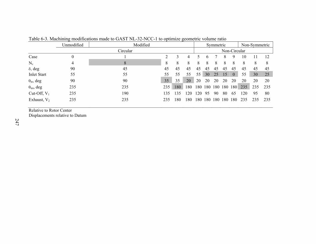
247
Table 6-3. Machining modifications made to GAST NL-32-NCC-1 to optimize geometric volume ratio Unmodified Modified Symmetric Non-Symmetric Circular Non-Circular Case 0 1 2 3 4 5 6 7 8 9 10 11 12 Nv 4 8 8 8 8 8 8 8 8 8 8 8 8 δ, deg 90 45 45 45 45 45 45 45 45 45 45 45 45 Inlet Start 55 55 55 55 55 55 30 25 15 0 55 30 25 θin, deg 90 90 35 35 20 20 20 20 20 20 20 20 20 θex, deg 235 235 235 180 180 180 180 180 180 180 235 235 235 Cut-Off, V1 235 190 135 135 120 120 95 90 80 65 120 95 80 Exhaust, V2 235 235 235 180 180 180 180 180 180 180 235 235 235 Relative to Rotor Center Displacements relative to Datum

248
Figure 6-12. Unmodified, modified symmetric and non-symmetric non-circular Expander (All dimensions in inches)
Exhaust angle 235 deg
Exhaust angle 235 deg

249
Figure 6-13. Schematic of the experimental set-up for compressed air and R-22 tests with a rotary-vane expander
M
T
P
Multi-vane Expander
T
P
DLC
P
Cooling Compressed Air
P: Pressure transducer T: Thermocouple M: Mass-flow rate meter DLC: Dynamometer, Load-cell & Controller
Valve
Pressure Regulator
Compressed Air/R-22 Supply

250
CHAPTER 7 CONCLUSIONS AND RECOMMENDATIONS
This chapter is a summary of the challenges, recommendations and conclusions of
both the comprehensive modeling and experimental effort.
The successful assessment of the performance of a two-phase rotary-vane expander
utilized in vapor compression refrigeration systems (VCRS) based on the results from
extensive experimentation and a comprehensive component-level thermodynamic and
fluid mechanic model has been made. Key technical challenges are realized from both
primary (internal leakage, friction and throttling) loss mechanisms as well as those of
secondary consequence (re-compression, under or over-expansion, lubrication etc).
Internal Leakage Losses
Leakage losses from a majority of leakage paths cannot be necessarily neglected in
two-phase rotary-vane expanders. Unlike single-phase rotary-vane turbomachinery,
significant variations in density and speed of sound, inherent with the vaporization of
liquid, significantly alters the leakage flow-rates. This due to a greater mass flux of two-
phase leakage in expanders when compared to conventional technology (i.e. compressors
and air-motors) that results from the following:
• Choking in leakage paths, i.e. maximum leakage flow-rate, occurs at higher back pressures. Figure 7-1 illustrates the difference in the critical-pressure ratio required to realize choked flow for typical operating conditions in expanders and compressors, respectively. Both processes are isentropic. In the case of the expander, the fluid is initially a saturated liquid at the condensing temperature. The fluid then accelerates, necessitating the formation of vapor, and the velocity approaches that of the speed of sound if the back pressure is low enough. In the case of the compressor, the saturated vapor is assumed to undergo isentropic compression to the condensing temperature. The specific heat ratio is larger at higher condensing temperatures leading to a smaller critical-pressure ratio. It can be shown that for all practical purposes, the critical-pressure ratio for R-22 vapor in the temperature range of 0oC<T<60oC is 0.54.

251
• Significant variation of the refrigerant’s density in the two-phase region. Internal leakage has the greatest impact on a two-phase rotary-vane expander’s performance during the charging and expansion processes. These are regions where the largest pressure differentials between cells exists (i.e. the driving potential) and also where the density of the refrigerant is significantly large. Although the speed of sound (or velocity if not choked) in a two-phase medium is smaller than that of a vapor refrigerant, the discrepancy between the density has a much more dominant effect on the mass flow-rate of leakage.
• Gap sizes in conventional rotary-vane turbomachinery are extremely large. Larger gaps exist due to the significantly smaller density of the working fluid in the gaps between the moving parts in conventional rotary-vane machinery. These clearances must be reduced to within acceptable limits for the proper operation of a two-phase device. Hence a special set of design criteria must be addressed.
• Uncertainty in gap sizes. Uncertainties in regard to quantifying gap sizes are a significant obstacle to predicting the magnitude of leakage losses through all the leakage paths during operation. This can be attributed to bearing end-play which alters the clearances in two dimensions. Proper design of the bearing housing may influence this. The deformation of the end-plates due to high pressure stresses will also alter clearances and may cause separation of boundary-layers and the transition to turbulence between the rotor and stationary end-plates.
• The leakage losses from the non-axisymmetric flow in the axial gap between the rotor and end-plates is most significant. The magnitude of leakage losses through this path during the intake and expansion processes has a significant impact on the efficiency of the expansion device.
• Radial leakage through the minimum clearance between the stator and rotor cylinders greatly restricts the design and optimization of the intake angle spread and location. Depending on degree of subcooling, the density of the incoming fluid is substantially large. The magnitude of the leakage from this path depends on the spread and location of the intake port. The detrimental affect of re-expansion losses in compressors is significantly smaller than that of radial leakage in a two-phase expander. A decrease in the number of vanes increases the contribution of leakage through the minimal radial gap between the rotor and stator cylinder. The increase of the number of vanes however increases the potential of internal leakage via other paths, increases frictional losses and decreases the mechanical strength of the rotor.
Friction
The curvature of the vane-tip can severally impact the amount of leakage past the
vane-tips due to loss of contact with the stator-cylinder. Even if no throttling is assumed
in the intake port, there is a loss of contact with the stator-cylinder through out the
252
duration of the expansion process. The method used to provide continuous contact
between the vane-tips and stator-cylinder is essential to optimum performance. A trade-
off exists between the throttling losses and increased frictional losses attributed to the
method by which the incoming working fluid is introduced into the expander cavity.
Vanes should be made out of high-density materials that can erode and mold to the stator-
cylinder geometric curvature. This would eliminate the need for adequate under-vane
forces through intake ports or cumbersome, unreliable springs.
Other Issues
Depending on the flow conditions, throttling losses in two-phase flow expanders
are significantly larger than in single-phase flow expanders. It has been shown that the
volumetric efficiency of a two-phase rotary-vane expander is extremely sensitive to the
design of the intake port. For a poorly designed intake port (low Cd), the volumetric
efficiency is approximately 50-60%. For a single-phase expander the volumetric
efficiency is expected to be 75-90%, due to the insignificant density variation that is
inherent with the vaporization of liquid.
A detailed intake model must be developed if two or more expander cells are in
communication with the intake port. The throat that the expander cell makes with the
intake port is expected to be the major flow restriction. Throttling losses in the exhaust
port may be neglected when compared to the charging process since velocities associated
with the discharge process are typically less and the flow area in the exhaust port is
significantly larger.
In vapor compression refrigeration technology the lubricant used is soluble and
circulates freely within the system. A dedicated lubrication loop within a hermetic rotary-
vane expander may significantly reduce friction between sliding parts. The thin film of

253
lubricant will also reduce gap sizes and alter internal leakage flows. The lubrication of
the shaft bearings is accounted for by using sealed, pre-lubricated ball bearings.
Leakage ratio, Expander sizing and Integration Concepts
In order to harness the maximum amount of work out-put from an expander,
different integration concepts must be evaluated according to operational speed
requirements, ease of coupling and requirements related to capacity control and system
performance. This task includes in-depth off-design calculations that result in
significantly different inlet conditions and mass flow-rates of the working fluid. An
expander is sized so that the volumetric flow-rate through the expander is equal to the
volumetric flow-rate of refrigerant at the condenser exit.
• The amount of leakage is seen to increase due to a larger contribution from the leakage mass flow-rate through the radial gap, minimum clearance, between the rotor and stator-cylinder. Caution must be exercised when increasing the number of vanes due to possible increases in friction and decrease of mechanical strength of the rotor.
• Sizing of the rotary-vane expander for two-phase applications is critical with regard to determining the optimum operational speed to reduce the loss mechanisms presented above.
• Inadequate sizing may lead to under-expansion. Depending on the order of magnitude of under-expansion, an economizer cycle may be a promising modification that would allow the use of two expansion devices in series with a separator between them. In this case there would be greater flexibility in the geometric design and operational speed of the expander.
• Increase in rotational speed decreases internal leakage losses through the expander significantly. Extensive detailed modeling and experimentation is needed to determine the magnitude of detrimental effects such as friction and viscous drag.
• The application of an expansion device in a refrigeration system should be primarily based on the system mass flow-rate. For a given set of operational conditions, the cooling capacity will ultimately determine the geometric size of the expander, the degree of impact of the primary and secondary loss mechanisms and the rotational speed of the expander.

254
• Once the rotational speed and the actual work out-put from the expansion device has been determined, the expander’s shaft may be integrated in various configurations. The generated power from the expander can be:
• Coupled to the compressor on the same shaft. The matching of rotational speed and the complexity of a gearing system otherwise increase the complexity of this integration concept.
• Used to drive auxiliary equipment in the VCRS. This integration concept allows for the most flexible use of the power generated by the expander. The vapor compression refrigeration system has many components that require power such as fans, pumps, control devices etc.
• Used to drive external equipment. This is another flexible integration concept that allows equipment such as air compressors or stand-alone cycles to be driven by the expander. One promising alternative is to use the out-put power to drive a dedicated or integrated subcooling cycle.
Figure 7-2 illustrates a typical expander sizing diagram. The diagram accounts for
the nominal cooling capacity of the refrigeration unit, the displacement volume of an
expansion device and the operational speed of that device for a given set of operational
conditions. The two operating points detailed on the figure represent the current design
point of a smaller deployable refrigeration unit and that of the minimum design condition.
The current design point is that of a small expansion device operating at a low rotational
speed due to the smaller cooling capacity of the unit. The minimum design point
represents a design condition where the system mass flow-rate is significantly larger than
the leakage flow-rate, the rotational speed of the expander is sufficiently large to reduce
leakage losses and the geometric size of the expander is sufficiently large for reduced
machining cost associated with less “strict” tolerances between the moving parts.
Recommendations
Great potential for use of a rotary-vane expander as a throttle-valve replacement
has been presented analytically. The absence of complicated geometric profiles (e.g.
screw, scroll) and complex valve timing and controls (e.g. reciprocating piston) make the

255
rotary-vane expander a viable candidate. Valve timing is inherent through geometry and
the principles of operation. This eliminates the need for complex models for valve
dynamics and pulsation effects.
Due to the aforementioned summary of technical challenges and limitations, the
following can be recommended
• Existing rotary-vane technology is limited by the aforementioned technical challenges and limitations which prevent a drop-in vane expander from being developed as a retrofit.
• Specialized design recommendations must be considered when re-engineering current rotary-vane technology.
• System-oriented optimization that accounts for and overcomes the limitations alluded to in the set of comprehensive findings presented must be made.
• The leakage losses from the non-axisymmetric flow in the axial gap between the rotor and end-plates is the most significant leakage path. The model developed is relatively ideal in its assumptions and doesn’t take into account separated boundary layers, choking or turbulent fluid flow. A computational model must solve the compressible Navier-Stokes equations in order to do so.
• Although there exists a trade-off between reducing internal leakage losses and increasing frictional losses, internal leakage losses must be reduced in order to achieve suitable expander operation. This task should be given priority. As mentioned, internal leakage losses may be reduced by proper selection of design parameters and detailed engineering of tolerances and clearances. The use of a dedicated lubrication system may also significantly alter the characteristics of internal leakage.
• Detailed analyses of the flow distribution within the complex geometry of two-phase rotary-vane expanders must be carried using computational fluid dynamics. The solution of the compressible governing equations in this complex flow field will yield, among many others, the following
• Gradients of pressure and density with the expander cavity
• Prediction of viscous dissipation due to the formation of vortices during the charging and discharging processes
• A comprehensive account of all leakage potentials and phenomena
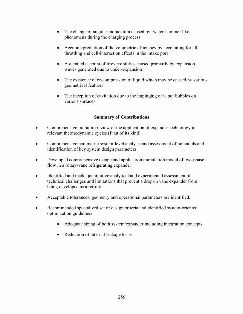
256
• The change of angular momentum caused by ‘water-hammer like’ phenomena during the charging process
• Accurate prediction of the volumetric efficiency by accounting for all throttling and cell-interaction effects in the intake port
• A detailed account of irreversibilities caused primarily by expansion waves generated due to under-expansion
• The existence of re-compression of liquid which may be caused by various geometrical features
• The inception of cavitation due to the impinging of vapor bubbles on various surfaces
Summary of Contributions
• Comprehensive literature review of the application of expander technology in relevant thermodynamic cycles (First of its kind)
• Comprehensive parametric system-level analysis and assessment of potentials and identification of key system design parameters
• Developed comprehensive (scope and application) simulation model of two-phase flow in a rotary-vane refrigerating expander
• Identified and made quantitative analytical and experimental assessment of technical challenges and limitations that prevent a drop-in vane expander from being developed as a retrofit.
• Acceptable tolerances, geometry and operational parameters are identified.
• Recommended specialized set of design criteria and identified system-oriented optimization guidelines
• Adequate sizing of both system/expander including integration concepts
• Reduction of internal leakage losses
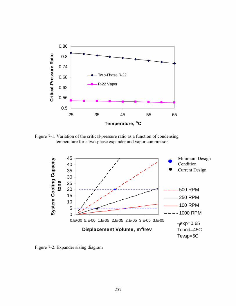
257
0.5
0.56
0.62
0.68
0.74
0.8
0.86
25 35 45 55 65
Temperature, oC
Criti
cal-P
ress
ure
Ratio
Tw o-Phase R-22
R-22 Vapor
Figure 7-1. Variation of the critical-pressure ratio as a function of condensing temperature for a two-phase expander and vapor compressor
Figure 7-2. Expander sizing diagram
05
1015202530354045
0.E+00 5.E-06 1.E-05 2.E-05 2.E-05 3.E-05 3.E-05
Displacement Volume, m3/rev
Sys
tem
Coo
ling
Cap
acity
to
ns
500 RPM250 RPM100 RPM1000 RPM
Cut-off
Proposed
ηexp=0.65Tcond=45CTevap=5C
Current Design
Minimum Design Condition

258
LIST OF REFERENCES
Alphonso, J.Z., 2003. Proof of Concept of the Ion Collider in Refrigeration Systems, M.S. Thesis. Department of Mechanical and Aerospace Engineering, University of Florida, Gainesville, FL.
Badr, O., Naik, S., and O’Callaghan, P.W., 1991b. Expansion Machine for a Low Power-Output Steam Rankine-Cycle Engine. Applied Energy 39, 93-116.
Badr, O., Naik, S., O’Callaghan, P.W., and Probert, S.D., 1991a. Rotary Wankel Engines as Expansion Devices in Steam Rankine-Cycle Engines. Applied Energy 39, 59-76.
Badr, O., Naik, S., O’Callaghan, P.W., and Probert, S.D., 1991c. Wankel Engines as Steam Expanders: Design Considerations. Applied Energy 40, 157-170.
Badr, O., O’Callaghan, P.W., and Probert, S.D., 1985a. Multi-Vane Expanders: Geometry and Kinematics. Applied Energy 19, 159-182.
Badr, O., O’Callaghan, P.W., and Probert, S.D., 1985b. Multi-Vane Expander Performance: Breathing Characteristics. Applied Energy 19, 241-271.
Badr, O., O’Callaghan, P.W., Hussein, M., and Probert, S.D., 1984. Multi-vane Expanders as Prime Movers for Low-Grade Energy Organic Rankine-Cycle Engines. Applied Energy 16, 129-146.
Badr, O., Probert, S.D, and O’Callaghan, P., 1985c. Multi-vane Expanders: Internal-Leakage Losses. Applied Energy 20, 1-46.
Badr, O., Probert, S.D., and O’Callaghan, P., 1986a. Multi-Vane Expanders: Vane Dynamics and Friction Losses. Applied Energy 20, 253-285.
Badr, O., Probert, S.D., and O’Callaghan, P.W., 1986b. Influences of Vane Design and Lubricant on a Multi-vane Expander’s Performance. Applied Energy 22, 271-298.
Baehr, H.D. and Tillner-Roth, R., 1995. Thermodynamic Properties of Environmentally Acceptable Refrigerants – Equations of State and Tables for Ammonia, R22, R-134a, R-152a, and R-123. Springer-Verlag.
Baek, J., Groll, E.A., Lawless, P.B., 2005a. Piston-Cylinder Work Producing Expansion Device in a Transcritical Carbon Dioxide Cycle Part I: Experimental Investigation. International Journal of Refrigeration 28 (2), 141-151.
Baek, J., Groll, E.A., Lawless, P.B., 2005b. Piston-Cylinder Work Producing Expansion Device in a Transcritical Carbon Dioxide Cycle Part II: Theoretical Model. International Journal of Refrigeration 28 (2), 152-164.

259
Baek, J.S., Groll, E.A., and Lawless, P.B., 2002. Development of a Carbon Dioxide Based Field Deployable Environmental Control Unit to Replace HCFC-22 or HFC-134A Units. Final Report submitted to the Air Force Research Laboratory, Report #1662-1.
Baron, S. and Trembley, J., 2003. Cryogenic Re-Refrigeration, Or How to Freeze Food More Economically Using Indirect Heat Exchange and Turbo-Expansion. In: Proceedings of the 21st International Congress of Refrigeration, Washington, D.C., USA, Paper No. ICR0267.
Barszcz, Z., 1980. Dynamic Analysis of Pneumatic Vane Motors. Archiwumbudowy maszyn, Archive of Mechanical Engineering 27 (1), 25-39.
Beck, W.D., Stein, R.A., and Eibling, J.A., 1966. Design for Minimum Friction in Rotary-Vane Refrigeration Compressors. ASHRAE Transactions 72 (Part 1), No. 1974, 190-197.
Bein, M., Shavit, A and Solan, A., 1976. Non-axisymmetric flow in the narrow gap between a rotating and a stationary disk. ASME Journal of Fluid Engineering, June, 217-223.
Ben-Bassat, I., and Wolgemuth, C.H., 1972. Simulation of a Two-stage Rotary-vane Steam expander. SAE No. 720737, September 11-14, 11-18.
Bransford, E.O., and Stein, R.A., 1960. Design Control of Over-compression in Rotary-Vane Compressors. Transactions of the ASME, Journal of Engineering Gas Turbines for Power, July, 221-226.
Brasz, J.J., 1995. Improving the Refrigeration Cycle with Turbo-Expander. In: Proceedings of the 19th International Congress of Refrigeration Vol. IIIa, The Hague, The Netherlands, August 20-25, 246-253.
Brasz, J.J., Smith, I.K. and Stosic, N., 2000. Development of a Twin Screw Expressor as a Throttle Valve Replacement for Water-Cooled Chillers. In: Proceedings of the 15th International Compressor Engineering Conference at Purdue Vol. 2, Purdue University, West Lafayette, IN, July 25-28, 979-986.
Carey, V.P., 1992. Liquid-Vapor Phase-Change Phenomena: An Introduction to the Thermo-physics of Vaporization and Condensation in Heat Transfer Equipment. Hemisphere Publishing.
Cavallini A., 1996. Working Fluids for Mechanical Refrigeration. Presented at the 19th International Congress of Refrigeration, The Hague, August 1995, Review Paper, International Journal of Refrigeration 19 (8), 485-496.
Cerepnalkovski, I., 1991. Modern Refrigerating Machines. Elsevier Publishing Company.

260
Chang, Y.S., Kim, M.S. and Ro, S.T., 2000. Performance and Heat Transfer Characteristics of Hydrocarbon Refrigerants in a Heat Pump System. International Journal of Refrigeration 23, 232-242.
Colbourne, D. and Suen, K.O., 2004a. Appraising the Flammability Hazards of Hydrocarbon Refrigerants Using Quantitative Risk Assessment Model Part I: Modeling Approach. International Journal of Refrigeration 27, 774-783.
Colbourne, D. and Suen, K.O., 2004b. Appraising the Flammability Hazards of Hydrocarbon Refrigerants Using Quantitative Risk Assessment Model Part II: Model Evaluation and Analysis. International Journal of Refrigeration 27, 784-793.
Collier, J.G., 1972. Convective Boiling and Condensation, McGraw Hill.
Daily, J.W. and Nece, R.E., 1960. Chamber Dimension Effects on Induced Flow and Frictional Resistance of Enclosed Rotating Disks. ASME Journal of Basic Engineering, March, 217-232.
Darby, R., 2001. Chemical Engineering Fluid Mechanics, 2nd Edition. CRC Press.
Disawas, S. and Wongwises, S., 2004. Experimental Investigation on the Performance of the Refrigeration Cycle using a Two-Phase Ejector as an Expansion Device. International Journal of Refrigeration 27, 587-594.
Dlugogorski, B.Z., Hichens, R.K. and Kennedy, E.M., 2002. Inert Hydrocarbon-based Refrigerants. Fire Safety Journal 37, 53-65.
Driver, R.W. and Davidson, D.P., 1999. Applications for the Hinge-vane Positive Displacement Compressor-Expander. IMechE Conference on Compressors and their Systems, City University, London, England.
Driver, R.W., 1996. A Rotary Positive Displacement Heat Pump Compressor and Turbine Combined in One Rotor. In: Proceedings of the 1996 International Compressor Conference at Purdue, July 23-26, West Lafayette, IN.
Edwards, T.C. and McDonald, A.T., 1972. Analysis of Mechanical Friction in Rotary Vane Machines. In: Proceedings of the Purdue Compressor Technology Conference, July 25-27, 250-262, West Lafayette, IN.
Ertesvag, I.S., 2002. Analysis of the Vading Concept-A New Rotary-Piston Compressor, Expander, and Engine Principle. In: Proceedings of IMechE Part A: Journal of Power and Energy 216 (3), 283-290.
Fartaj, A., Ting, D.S.K. and Yang, W.W., 2004. Second law Analysis of the Transcritical CO2 Refrigeration Cycle. Energy Conversion and Management 45, 2269-2281.

261
Fischer, R.D., 1978. Feasibility Study and Hardware Design of a Pivoting-Tip Rotary-vane Compressor and Expander Applied to a Solar-Driven Heat Pump. In: Proceedings of the 4th International Compressor Engineering Conference at Purdue, Purdue University, West Lafayette, IN, 233-240.
Fukuta, M., Yanagisawa, T. and Radermacher, R., 2003. Performance Prediction of Vane Type Expander for CO2 Cycle. In: Proceedings of the 21st International Congress of Refrigeration, Washington, D.C., USA, Paper No. ICR0251.
Gnutek, Z. and Kalinowski, E., 1986. Use of a Rotary Blade Compressor and Expander in the Refrigeration Cycles. In: Proceedings of the 8th International Compressor Engineering Conference at Purdue Vol. 3, Purdue University, West Lafayette, IN, August 4-7, 1026-1034.
Gnutek, Z., 1979. Mathematical Model of a Rotary Expander with Movable Rotor Blades. In: Proceedings of the XVth International Congress of Refrigeration, Volume I: Progress in Refrigeration Science and Technology, Venezia, Italy, 529-536.
Granryd E., 2001. Hydrocarbons as Refrigerants – An Overview. International Journal of Refrigeration 24, 15-24.
Hammad, M.A. and Alsaad, M.A., 1999. The Use of Hydrocarbon Mixtures as Refrigerants in Domestic Refrigerators. Applied Thermal Engineering 19, 1181-1189.
Hays, L. and Brasz J.J., 2004. A Transcritical CO2 Turbine-Compressor. In: Proceedings of the 17th International Compressor Engineering Conference at Purdue, Purdue University, West Lafayette, IN, July 12-15, Paper C137, 1-7.
Hays, L.G. and Brasz, J.J., 1996. Two-Phase Turbines for Compressor Energy Recovery. In: Proceedings of the 13th International Compressor Engineering Conference at Purdue Vol. 2, Purdue University, West Lafayette, IN, July 23-26, 657-662.
Hays, L.G. and Brasz, J.J., 1998. Two-Phase flow Turbines as Stand-Alone Throttle Replacement Units in Large 2000-5000 Ton Centrifugal Chiller Installations. In: Proceedings of the 14th International Compressor Engineering Conference at Purdue, Purdue University, West Lafayette, IN, July 14-17, 797-802.
Henderson, P.C., Hewitt, N. J. and Mongey, B., 2000. An Economic and Technical Case for a Compressor/Expander Unit for Heat Pumps. International Journal of Energy Research 24, 831-842.
Heyl, P. and Quack, H., 1999. Free Piston Expander-Compressor for CO2-Design, Applications and Results. In: Proceedings of the 20th International Congress of Refrigeration Vol. III, Sydney, Australia, Paper No. ICR0516.

262
Heyl, P., Kraus, W. E. and Quack, H., 1998. Expander-Compressor for a More Efficient Use of CO2 as Refrigerant. In: Proceedings of the ’98 IIR-Gustav Lorentzen Conference on Natural Working Fluids, Oslo, Norway, 240-248.
Huff, H. and Radermacher, R., 2003. Experimental Investigation of a Scroll Expander in a Carbon Dioxide Air-Conditioning System. In: Proceedings of the 21st International Congress of Refrigeration, Washington, D.C., USA, Paper No. ICR0485.
Huff, H., Lindsay, D. and Radermacher, R., 2002. Positive Displacement Compressor and Expander Simulation. In: Proceedings of the 16th International Compressor Engineering Conference at Purdue, Purdue University, West Lafayette, IN, July 16-19, 209-215.
Incropera, F. P. and Dewitt, D. P., 2002. Fundamentals of Heat and Mass Transfer, 5th Edition, John Wiley & Sons Inc.
Jacazio, G., Piombo, B., Romiti, A. and Sola, A., 1979. The Optimization of the Performance of Vane-type Air Motors. In: Proceedings of the Fifth World Congress on Theory of Machines and Mechanisms, Montreal, Canada, July 8-13.
Jung, D., Kim, C.B., Song, K. and Park, B., 2000. Testing of Propane/Isobutane Mixture in Domestic Refrigerators. International Journal of Refrigeration 23, 517-527.
Kauf, F., 1999. Determination of the Optimum High pressure for Transcritical CO2 Refrigeration Cycles. International Journal of Thermal Sciences 38, 325-330.
Kim, M.H, Pettersen, J. and Bullard, C.W., 2004. Fundamental Process and System Design Issues in CO2 Vapor Compression Systems. Progress in Energy and Combustion Science 30, 119-174.
Kim, Y.M., Shin, D.K., and Lee, J.H., 2004. A Scroll Expander with Heating Structure and their Systems. In: Proceedings of the 17th International Compressor Engineering Conference at Purdue, Purdue University, West Lafayette, IN, July 12-15, Paper C024, 1-8.
Kornhauser, A., 1990. The Use of an Ejector as a Refrigerant Expander. Preprints of the 1990 USNC/IIR Purdue Refrigeration Conference and the 1990 ASHRAE-Purdue CFC Conference, Purdue University, West Lafayette, IN, July 17-20, 10-19.
Lemmon, E.W., McLinden, M.O. and Huber, M.L., 2002. REFPROP: Reference Fluid Thermodynamic and Transport Properties. NIST Standard Reference Database 23, Version 7.0.
Levy, S. 1999. Two-Phase Flow in Complex Systems, John Wiley & Sons.
Li, D. and Groll, E.A., 2005. Transcritical CO2 Refrigeration Cycle with Ejector-Expansion Device. International Journal of Refrigeration 27 (5), 766-773.

263
Li, D., Baek, J.S., Groll, E.A., and Lawless, P.B., 2000. Thermodynamic Analysis of Vortex Tube and Work Output Expansion Devices for the Transcritical Carbon Dioxide Cycle. In: Proceedings of the 4th IIR-Gustav Lorentzen Conference on Natural Working Fluids at Purdue, Purdue University, West Lafayette, IN, 433-440.
Lorentzen, G. and Pettersen, J., 1993. A New, Efficient and Environmentally Benign System for Car Air-conditioning. International Journal of Refrigeration 16 (1), 4-12.
Lorentzen, G., 1994. The Revival of Carbon Dioxide as a Refrigerant. International Journal of Refrigeration 17 (5), 292-301.
Markoski, M., 2003. Improvement Possibilities of Vapor Compression Refrigerating Cycles by Utilization of Expansion Engines. In: Proceedings of the 21st International Congress of Refrigeration, Washington, D.C., USA, Paper No. ICR0006.
Marsters, G.F., and Ogbuelfi, E., 1972. Rotary-vane Expander Development: Some Design Considerations. In: IECEC Conference Proceedings (729), 249-254.
Newton, A.B., 1972a. Controls for a Multi-Phase Ejector Refrigeration System. US Patent Number 3,670,519, Assigned to Borg-Warner Corporation, Chicago, IL.
Newton, A.B., 1972b. Controls for a Multi-Phase Ejector Refrigeration System. US Patent Number 3,701,264, Assigned to Borg-Warner Corporation, Chicago, IL.
Nickl, J., Will, G., Kraus, W.E. and Quack, 2003. Third Generation CO2 Expander. In: Proceedings of the 21st International Congress of Refrigeration, Washington, D.C., USA, Paper No. ICR0571.
Nickl, J., Will, G., Kraus, W.E., and Quack, H., 2002. Design Considerations for a Second Generation CO2 Expander. In: Proceedings of the 5th IIR-Gustav Lorentzen Conference on Natural Working Fluids at Guangzhou, China, 189-196.
Oosthuizen, P.H., and Carscallen, W.E., 1997. Compressible Fluid Flow, McGraw-Hill.
Peterson, C.R. and McGahan, W.A., 1972. Thermodynamic and Aerodynamic Analysis Methods for Oil Flooded Sliding Vane Compressors. In: Proceedings of the Purdue Compressor Technology Conference, July 25-27, 1-8.
Preissner, M., 2001. Carbon Dioxide Vapor Compression Cycle Improvements with Focus on Scroll Expanders, Ph.D. Dissertation. University of Maryland, College Park, MD.
Purkayastha, B. and Bansal, P.K., 1998. An Experimental Study on HC290 and a Commercial Liquefied Gas (LPG) Mix as Suitable Replacements for HCFC22. International Journal of Refrigeration 21 (1), 3-17.

264
Robertson, G.F. and Wolgemuth, C.H., 1975. Analysis and Test Apparatus for a Vane Expander Using Steam. In: Proceedings of the Intersociety Energy Conversion Engineering Conference (IECEC), August 18-22, Paper No. 759205, 1406-1410.
Robertson, G.F. and Wolgemuth, C.H., 1978. Experimental and Analytical Study of Friction, Leakage and Heat Transfer in a Vane Expander. In: Proceedings of the Intersociety Energy Conversion Engineering Conference (IECEC), August 20-25, Paper No. 789521, 1430-1441.
Robinson, D.M. and Groll, E.A., 1998a. Efficiencies of Transcritical CO2 Cycles with and without an Expansion Turbine. International Journal of Refrigeration 27 (7), 577-589.
Robinson, D.M. and Groll, E.A., 1998b. Heat Transfer Analysis of Air-to-Carbon-Dioxide Two-Phase Heat Absorption and Supercritical Heat Rejection. International Journal of Heating, Ventilating, Air-Conditioning and Refrigerating (HVAC&R) Research 4 (4), 327-345.
Schmidt, J. and Friedel, L., 1997. Two-Phase Pressure Drop Across Sudden Contractions in Duct Areas. International Journal of Multiphase Flow 23 (2), 283-299.
Sekhar, S.J., Lal, D.M. and Renganarayanan, S., 2004. Improved Energy Efficiency for CFC Domestic Refrigerators Retrofitted with Ozone-friendly HFC134a/HC Refrigerant Mixtures. International Journal of Thermal Sciences 43, 307-314.
Smith, I.K. and da Silva, R.P.M., 1994. Development of the Trilateral Flash Cycle System Part 2: Increasing Power Output with Working Fluid Mixtures. Proceedings of the Institution of Mechanical Engineers. Part A: Journal of Power and Energy 208, 135-144.
Smith, I.K. and da Silva, R.P.M., 1996. Development of the Trilateral Flash Cycle System Part 3: Increasing Power Output with Working Fluid Mixtures. Proceedings of the Institution of Mechanical Engineers. Part A: Journal of Power and Energy 210, 75-93.
Smith, I.K. and Stosic, N., 1995. The Expressor: An Efficiency Boost to Vapour Compression Systems By Power Recovery from the Throttling Process. Heat Pump and Refrigeration Systems Design, Analysis and Applications, presented at the 1995 ASME International Mechanical Engineering Congress, November 12-15, AES-Vol. 34, 173-181.
Smith, I.K., 1993. Development of the Trilateral Flash Cycle System Part 1: Fundamental Considerations. Proceedings of the Institution of Mechanical Engineers. Part A: Journal of Power and Energy 207, 179-194.
Smith, I.K., Harrison, H.R. and Cox, M., 1990. A Preliminary Evaluation of the Groll Rotary Vane Compressor. In: Proceedings of the 1990 International Compressor Engineering Conference at Purdue, Vol. 1.

265
Smith, I.K., Harrison, H.R., and Cox, M., 1992. Preliminary Evaluation of the Groll Rotary Vane Compressor. International Journal of Refrigeration 15 (2), 69-73.
Smith, I.K., Stosic, N. and Aldis, C.A., 1994. Lysholm Machines as Two-Phase Expanders. In: Proceedings of the 12th International Compressor Engineering Conference at Purdue, Vol. 1, Purdue University, West Lafayette, IN, July 19-22, 61-66.
Smith, I.K., Stosic, N. and Kovacevic, A., 2001a. Twin Screw Machines to Replace Throttle Valves in Refrigeration Systems. Strojniski vestnik: Journal of Mechanical Engineering 47 (8), 484-490.
Smith, I.K., Stosic, N. and Kovacevic, A., 2001b. Power Recovery from Low Cost Two-phase Expanders. Geothermal Research Council Annual Meeting, San Diego, CA.
Smith, I.K., Stosic, N., Aldis, C.A. and Kovacevic, A., 1999. Twin Screw Two-Phase Expanders in Large Chiller Units. IMechE International Conference on Compressors and Their Systems, City University, London, England, September.
Somayajulu, K.D.S.R., 1971. An Analysis of Vane-in-Rotor Pump. Transactions of the ASME, Journal of Basic Engineering, December, 505-517.
Stoecker, W.F., 1998. Industrial Refrigeration Handbook, McGraw-Hill.
Stosic, N., Smith, I.K. and Kovacevic, A., 2002. A Twin Screw Combined Compressor and Expander for CO2 Refrigeration Systems. In: Proceedings of the 16th International Compressor Engineering Conference at Purdue, Purdue University, West Lafayette, IN, July 16-19, 703-710.
Tamura, I., Taniguchi, H., Sasaki, H., Yoshida, R., Sekiguchi, I., and Yokogawa, M., 1997. An Analytical Investigation of High-Temperature Heat Pump System with Screw Compressor and Screw Expander for Power Recovery. Energy Conversion and Management 38 (10-13), 1007-1013.
Taniguchi, H., Kudo, K., Giedt, W.H., Park, I. And Kumazawa, S., 1998. Analytical and Experimental Investigation of Two-Phase Flow Screw Expanders for Power Generation. Transactions of the ASME, Journal of Engineering for Gas Turbines and Power 110, October, 628-635.
Tashtoush, B., Tahat, M. and Shudeifat, M.A., 2002. Experimental Study of New Refrigerant Mixtures to Replace R12 in Domestic Refrigerators. Applied Thermal Engineering 22, 495-506.
Wolgemuth, C.H., and Olson, D.R., 1971. A Study of Breathing in Vane Type Expanders. IECEC Conference Proceedings, August 3-5, 249-1258.
266
Wongwises, S. and Chimres, N., 2005. Experimental Study of Hydrocarbon Mixtures to Replace HFC-134a in a Domestic Refrigerator. Energy Conversion and Management 46, 85-100.
Yang, J.L., Ma, Y.T., Li, M.X. and Guan, H.Q., 2005. Exergy Analysis of Transcritical Carbon Dioxide Refrigeration Cycle with an Expander. Energy 30, 1162-1175.
Zha, S., Ma, Y. and Sun, X., 2003. The Development of CO2 Expander in CO2 Transcritical Cycles. In: Proceedings of the 21st International Congress of Refrigeration, Washington, D.C., USA, Paper No. ICR0089.
Zhang, H. and Yu, B., 1992. Future of the Refrigeration Cycle with Expander. In: Proceedings of the 11th International Compressor Engineering Conference at Purdue, Vol. 1, Purdue University, West Lafayette, IN, July 14-17, 357-363.
Zoughaib, A. and Clodic, D., 2003. A Turbo-Expander Development for Domestic Refrigeration Appliances. In: Proceedings of the 21st International Congress of Refrigeration, Washington, D.C., USA, Paper No. ICR0144.

267
BIOGRAPHICAL SKETCH
Ahmad M. Mahmoud was born February 14, 1979 in Kitchener, Ontario, Canada,
where his father was a Ph.D. student in the Department of Mechanical Engineering at the
University of Waterloo: the apple has clearly not fallen far from the tree! Shortly after
his father’s graduation, Ahmad’s family immigrated to the USA and Ahmad lived in
Upstate New York and Connecticut, until the age of 13, where his father held faculty
positions. In 1992, Ahmad’s family moved to Kuwait where his father was hired as an
associate professor of mechanical engineering. Ahmad attended the Universal American
School until his high school graduation and then joined Kuwait University’s Department
of Mechanical Engineering as an undergraduate student in Fall of 1997. Ahmad ranked
2/150 in his graduating class. At Kuwait University, Ahmad also met his future wife, Ms.
Iman Al-Naggar, who was then a Molecular Biology undergraduate student at the same
university. The two got engaged in their last year of undergraduate education and
married upon graduation in June of 2002. A couple of months later, Ahmad and Iman
both started graduate school at the University of Florida, where Iman also obtained her
Ph.D. from the College of Medicine’s Interdisciplinary Program in Biomedical Sciences
in Spring 2008.
While at UF, Ahmad worked as a team leader at the Industrial Assessment Center
during his Master’s graduate education and served as president of the Gainesville
ASHRAE Chapter. Ahmad has also been active in a plethora of professional activities
while in graduate school.
Finally, Ahmad became a father when his daughter Salma was born on September
12, 2007.