analytical study of internal phenomena of inflatable
TRANSCRIPT

Analytical Study of Internal Phenomena of
Inflatable Flexible Membrane Dams in High-
temperature Environments
Takashi Nakamura and Hiroyuki Nitta Public Works Research Institute, Innovative Materials & Resources Research Center, Tsukuba, Japan
Email: [email protected], [email protected]
Abstract—In this study, a material model for inflatable
flexible membrane dam (IFMD) rubber membranes was
developed to determine the material properties for finite
element method (FEM) analyses by considering the
hyperelasticity of rubber composites. In addition to
investigating the analytical model at room temperature,
realistic models at higher temperatures of 40 °C and 60 °C
were studied to simulate the actual dry, hot daytime field
environments under which IFMDs operate. Validation
analyses were performed for these developed models,
comparing the tensile test results of rubbers and nylon
woven fabrics obtained from several temperature
environments. Internal stress analyses were conducted with
the developed model, and the concentrations of stress and
strain within the rubber membrane, which had not yet been
studied precisely, were investigated. The internal stresses,
strains, and deformations under room temperature and high
temperatures were analyzed and compared to confirm the
mechanical behaviors of the rubber membrane under tensile
loading. In addition, bending analyses of the rubber
membrane were conducted to understand the internal
phenomena of the bending portions.
Index Terms—inflatable dam, rubber dam, rubber–nylon
composite, hyperplastic body modeling, inner stress, FEM
I. INTRODUCTION
Inflatable flexible membrane dams (IFMDs), or
inflatable dams and rubber dams, are river weirs that use
air or water to inflate and deflate their structures to
control water levels. The first IFMD was introduced by
the US in the 1960s in Japan; approximately 3900 IFMDs
are currently used in Japan. IFMDs operated by the
Japanese Ministry of Land, Infrastructure and Transport
have various designs, ranging in span from 2 to 50 m and
height from 0.5 to 5 m. Some IFMDs are designed to
maintain service life for over 30 years. In order to realize
both long-term use and safety of the weirs, it is necessary
to establish effective maintenance and management
techniques for these structures. Fig. 1 shows an example
of an IFMD in Japan. Fig. 2 depicts a cross-section of one
rubber membrane used for IFMD structural bodies; it
uses a four-layer woven nylon fabric to provide strength
to the material.
Manuscript received August 10, 2017; revised April 14, 2018.
Regarding the damage to IFMDs during operation,
some dam failure modes relate to deformations of the
rubber membranes used for the structural bodies. The
fracture of the rubber portion between woven fabric
layers within the membrane is one of these failure modes,
and can cause serious structural damage. Therefore, it is
important to investigate the internal stress and
deformation of the membrane around joints and gaps in
the woven fabrics under actual operational environments. Although some studies have investigated the influence
of water flow on IFMD dynamic behaviors and overall structural vibrations, little research has been conducted regarding the internal phenomena of the rubber membranes under operational conditions [1]-[3]. In addition, insufficient analytical information is available regarding the material lifetime of rubber membranes; many questions about the operational durability of IFMDs remain, particularly regarding long-term use multiple decades [4].
One study investigated rubber membranes enforced by woven fabrics for another civil engineering structure: the long-term durability of rubber used for submerged tunnel joints was examined via computer simulation [5]. Other research studied fiber-reinforced rubbers as civil engineering materials and mechanical parts via analytical methods, in which material models were provided for
Figure 1. General view of IFMD
Figure 2. Cross-section of rubber membrane with joint portion
16 mm
EPDM
Nylon ×4 layers
Gap portion (minus one layer)
118
International Journal of Structural and Civil Engineering Research Vol. 7, No. 2, May 2018
© 2018 Int. J. Struct. Civ. Eng. Res.doi: 10.18178/ijscer.7.2.118-124
rubber membranes that accommodated rubber hyperelasticity and fabric viscosity, as well as dynamic property anisotropies [6]-[9]. These analytical models are applicable to IFMD rubber membranes to study their internal phenomena, which could clarify the complex internal stress fields of rubber composites, permit investigation of the rubber membrane structural failure mechanisms, allow prediction the lifetimes of rubbers, and enable optimization of the material strength and overall design of IFMDs.
In this study, a material model for IFMD rubber
membranes was developed to determine the material
properties for finite element method (FEM) analyses,
with consideration of the hyperelasticity of rubber
composites. In addition to investigating the analytical
model at room temperature, realistic models in high-
temperature conditions at 40 °C and 60 °C were studied
to simulate the actual field environments under which
IFMDs operate, particularly in dry and hot daytime
conditions. Validation analyses were performed for these
developed models, comparing the tensile tests results of
multiple rubbers and woven nylon fabrics under several
temperature environments. Internal stress analyses were
conducted with the developed model, and the
concentrations of stress and strain within the rubber
membrane, which have not yet been studied precisely,
were investigated. The internal stresses, strains, and
deformations at room temperature and higher
temperatures were analyzed and compared in order to
confirm the mechanical behaviors of rubber membranes
under tensile loading. In addition, bending analyses of the
rubber membrane were conducted to understand the
internal phenomena of the bending portions.
II. MATERIAL MODEL AND VALIDATION
A.
Material Model
Analytical models were developed to simulate large
deformations of IFMD rubber membranes via FEM. As
the material components, ethylene propylene diene
monomer (EPDM) rubber was used for the rubber portion
and woven nylon woven fabric was used for the layered
strengthening material.
Rubber is an incompressible material that experiences
large-strain nonlinear behavior. For modeling these
properties, the nine-parameter Mooney–Rivlin model was
employed in this study [10]. The form of the strain energy
potential for the nine-parameter Mooney–Rivlin model is:
W = C10(I1 - 3) + C01(I2 - 3) + C20(I1 - 3) +
C11(I1 - 3)(I2 - 3) + C02(I1 - 3)2
+ C30(I1 - 3)2
+ C21(I1 - 3)
2(I2 - 3) + C12(I1 - 3)(I2 - 3)
2
+
C03(I2 - 3)3 + 1/d (J - 1)
2, (1)
where: W = strain energy potential
I1, I2 = strain-invariant deviatory
Cij = material constants characterizing the deviation
deformations of the material
d = material compressibility parameter
J = determinant of the elastic deformation gradient F
For modeling the woven fabric portion, a linear elastic
model was used.
With these analytical models, the internal phenomena
of rubber membranes under tensile loading and bending
stresses were investigated with FEM.
B. Tensile Testing
Uniaxial tensile tests were conducted to determine the material constants for the rubber and woven fabric models. To understand the material characteristics at both ambient and high temperatures, to which IFMD rubber membranes are exposed during use in dry environments on hot days, the experiments were implemented at room temperature (~23 °C), 40 °C, and 60 °C for each material.
For the rubber tests, the specimens were rectangular strips measuring 150 × 10 × 10 mm. The initial chuck distance of the specimen was set to 40 mm and the test speed was 50 mm/min. Each test was conducted until sample breakage to obtain the nominal stresses and strains, which were determined by the chuck distances.
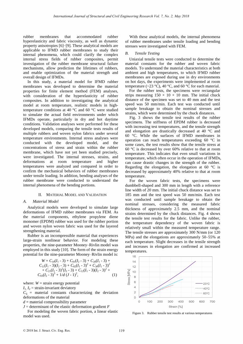
Fig. 3 shows the tensile test results of the rubber specimens. The stiffness of EPDM rubber is decreased with increasing test temperatures, and the tensile strength and elongation are drastically decreased at 40 °C and 60 °C. While the surfaces of IFMD membranes in operation can reach temperatures exceeding 60 °C in some cases, the test results show that the tensile stress at 60 °C is decreased by over 60% relative to that at room temperature. This indicates that even small variations in temperature, which often occur in the operation of IFMDs, can cause drastic changes in the strength of the rubber. Regarding the elongation, the elongation at 60 °C is decreased by approximately 40% relative to that at room temperature.
For the woven fabric tests, the specimens were
dumbbell-shaped and 300 mm in length with a reference
line width of 20 mm. The initial chuck distance was set to
185 mm and the test speed was 50 mm/min. Each test
was conducted until sample breakage to obtain the
nominal stresses, considering the measured fabric
thickness of approximately 2.5 mm, and the nominal
strains determined by the chuck distances. Fig. 4 shows
the tensile test results for the fabric. Unlike the rubber,
the temperature dependency of the woven fabric is
relatively small within the measured temperature range.
The tensile stresses are approximately 300 N/mm (or 120
MPa) and the elongations are approximately 50–55% at
each temperature. Slight decreases in the tensile strength
and increases in elongation are confirmed at increased
temperatures.
Figure 3. Rubber tensile test results at various temperatures
119
International Journal of Structural and Civil Engineering Research Vol. 7, No. 2, May 2018
© 2018 Int. J. Struct. Civ. Eng. Res.

C. Material Properties
The material constants of the rubber and woven fabric
were determined from the tensile test results. TABLE I
and TABLE II show the constants for rubber and fabric,
respectively. The rubber constants were obtained by
curve fitting of the tensile test results at each temperature.
The woven fabric constants were calculated using the
least-squares method for the tensile test results, assuming
material isotropy with the Poisson ratio of 0.4.
D. Validation
To confirm the validity of the analytical models,
verification analyses were conducted. The same sample
geometries and tests conditions as in the abovementioned
tensile test experiments were defined in FEM programs to
conduct tensile test analyses. The experimental and
analytical results were then compared. The displacement
of the chuck portion under each test condition was
compared for verification.
TABLE I . MATERIAL PROPERTY OF RUBBER
23 °C [MPa] 40 °C [MPa] 60 °C [MPa]
C10 5.88×10⁻¹ 3.46×10⁻¹ 2.60×10⁻¹
C01 4.71×10⁻² 1.85×10⁻² 4.03×10⁻²
C20 1.36×10⁻² 1.61×10⁻² 2.30×10⁻²
C11 1.19×10⁻³ 3.42×10⁻³ -1.29×10⁻³
C02 -1.78×10⁻⁴ -5.46×10⁻⁴ -4.12×10⁻⁴
C30 -1.29×10⁻⁴ -2.83×10⁻⁴ -6.30×10⁻⁴
C21 -1.45×10⁻⁵ 1.06×10⁻⁵ 2.70×10⁻⁴
C12 3.58×10⁻⁶ 9.07×10⁻⁶ -1.50×10⁻⁵
C03 -6.79×10⁻⁸ -2.15×10⁻⁷ 5.20×10⁻⁷
TABLE II . MATERIAL PROPERTY OF FABRIC
23 °C [MPa]
40 °C [MPa] 60 °C [MPa]
Young’s
modulus [MPa]
225.7 223.2 198.5
Poisson’s ratio 0.4
TABLE III . VERIFICATION OF ANALYSIS RESULTS
Error from experiment results [%]
23 °C 40 °C 60 °C
Rubber -7.6 +4.4 -3.3
Fabric -21.4 -29.1 -21.4
Table III shows the comparison between the
experimental and analytical results, thereby determining
the deviation from the experimental results For rubber,
behavioral verification tests at 23 °C, 40 °C, and 60 °C
were conducted under the tensile loads of 200 N, 141 N,
and 88 N. For the fabric, each condition was tested under
the tensile load of 6300 N. The analytical results with the
nine-parameter Mooney–Rivlin model, considering
material hyperelasticity, showed good agreement with the
experiment results. However, the woven fabric model
results are approximately 20–30% lower than the
experiment results, indicating that the analytical model is
somewhat stiffer than the actual material. In future
studies, the modeling of fabric isotropy and viscosity as
nonlinear material characteristics will be considered.
III. ANALYSIS CONDITIONS
A. Geometry
Fig. 5 shows the rubber membrane geometric model
for FEM analysis. This geometry represents the joint
portion of the IFMD rubber membrane, which includes
discontinuous woven fabric and is the weakest portion
within the IFMD membrane. Four gaps were introduced
in the model, and the stress concentrations and large-scale
deformations around them were investigated in detail.
The composite geometry was defined as having a
longitudinal length of 500 mm, width of 10 mm, and
layer-direction thickness of 16 mm. The membrane has
four nylon layers with gap distances of 8 mm each.
The model was meshed with 38410 elements. In terms
of constraint conditions, a weak spring model was set on
the longitudinal cross-section to prevent the entire model
from moving other than in the longitudinal direction.
Loads were applied in the longitudinal direction on
both edges to simulate uniaxial tensile stress, and the
stress distribution and deformation within the material
were confirmed. In addition to deformation by tensile
stresses, IFMD membranes experience large
deformations around bent portions under bending while
deflated or at the edge of the full structure while inflated.
Therefore, a bending analysis as illustrated in Fig. 6 was
performed.
Figure 4. Fabric tensile test results at various temperatures
120
International Journal of Structural and Civil Engineering Research Vol. 7, No. 2, May 2018
© 2018 Int. J. Struct. Civ. Eng. Res.

B. Analysis Sets
The inner stresses and deformations were confirmed
under the tensile load applied to the model representing
the inflated IFMD, and under bending displacements
applied to the bent portions.
To confirm the interior conditions created by tensile
loading, five load sets of 100 N, 250 N, 500 N, 2500 N,
and 5000 N were applied to the model in the longitudinal
direction. Each load set could be converted to nominal
stresses on the fabrics of 10 N/mm, 25 N/mm, 50 N/mm,
250 N/mm, and 500 N/mm, respectively. Here, the
reference strength of the rubber membrane (i.e., the fabric
strength) is 940 N/mm.
To confirm the interior condition induced by bending,
the model was bent to the radius of 300 mm (R300). The
deformation was simulated by bending the material to
make contact with a friction-free rigid body.
IV. RESULTS
Fig. 7 shows the analysis results for the tensile loading
of 2500 N at the temperature of 23 °C. Stress
concentrations develop in the rubber around the gaps, and
larger stresses are generated there than around the
continuous fabric portions. The same is confirmed in the
results for the fabric. In the results of both tensile loading
and bending analysis, the portions around the gaps
between woven fabrics within the membrane joint show
stress concentrations and large deformations under each
analysis condition. The following shows detailed analysis
results around Gap 1, shown in Fig. 5.
Fig. 8 and Fig. 9 show the analytical results
highlighting the major principal stress and principal strain
of the rubber. Each figure indicates results at both room
and high temperature (23 and 60 °C). Regarding the
temperature and high-temperature results are stresses
around the stress-concentrated part, the room-temperature
and high-temperature results are nearly equivalent. The
maximum strain in the high-temperature rubber is
approximately 1.6 times larger than that at room
temperature. This shows that the decreased stiffness of
rubber at higher temperatures causes larger deformation
than that observed at the room temperature.
Figure 7. Example of analytical result showing stress concentrations in rubber parts (tensile load of 2500 N at 23 °C)
Figure 6. Bending of rubber membrane to 300-mm radius
Figure 5. Geometry of IFMD rubber membrane FE model
121
International Journal of Structural and Civil Engineering Research Vol. 7, No. 2, May 2018
© 2018 Int. J. Struct. Civ. Eng. Res.

Fig. 10 and Fig. 11 show the analysis results for the
fabric, highlighting the major principal stress and
principal strain. The stresses of the fabric around the
stress concentrations are nearly equivalent at 23 and
60 °C. The maximum strain at 60 °C is approximately 1.2
times larger than that at 23 °C; however, this difference is
relatively small compared to that of rubber mentioned
above.
Fig. 12–15 show all analyzed data for the analysis sets,
indicating the maximum concentrations of stresses and
strains around the gaps. The horizontal lines of the graphs
represent the nominal stress applied to the rubber
membranes under the loading mentioned in section III;
these are normalized by dividing by the membrane
reference strength of 940 N/mm.
Fig. 12 shows the relation between the nominal stress
and maximum stress concentration within the rubber. The
result indicates that loading at less than the nominal stress
of 0.27 does not affect the stress difference between
temperatures. However, when the nominal stress is
increased to 0.53, the stress concentrations at 40 °C and
60 °C become remarkably higher than that at 23 °C. In
order to investigate the reason for this, the deformation
status of the rubber was reviewed. Increasing the
temperature caused severe compressive deformation of
certain elements in the rubber model around the gap.
Therefore, the maximum stress observed at 60°C reached
approximately twice the value for that at 23 °C, for
example. This analysis result suggests the importance of
strength design for rubber membranes considering high-
temperature conditions.
Figure 9. Analytical result of rubber strain distribution (tensile load of 2500 N)
Figure 8. Analytical result of rubber stress distribution (tensile load of 2500 N)
Figure 10. Analytical result of fabric stress distribution (tensile load of 2500 N)
Figure 11. Analytical result of fabric strain distribution (tensile load of 2500 N)
122
International Journal of Structural and Civil Engineering Research Vol. 7, No. 2, May 2018
© 2018 Int. J. Struct. Civ. Eng. Res.

Fig. 13 shows the relationship between the nominal
stress and the maximum concentration of strain within the
rubber. The results indicate that the strains depend on the
temperatures; increasing temperatures correspond to
increased strains. In this study, the rubber and woven
fabric viscosities are not included in the models. However,
the membranes practically experience creep; therefore,
the internal strains are time-dependent. Thus, larger
strains may form in structures during operation,
particularly over long-term use, than the strains analyzed
here. These results suggest that slight temperature
increases affect the maximum strain variations in the
rubber. Strains and elongations can be criteria of material
failures for polymeric materials. Thus, in addition to the
analysis results from this study, considerations of the
viscous behaviors of rubbers such as creep phenomena,
especially under high-temperature conditions, are
necessary for the material design and investigation of
IFMD durability.
Fig. 14 shows the relation between the nominal stress
and the maximum concentration of stress in the fabric. It
indicates a small temperature dependency of the
maximum stress of the fabric. Fig. 15 shows the
relationship between the nominal stress and maximum
strain concentration in the fabric. Here, the differences in
the fabric maximum strains at varied temperatures are
relatively small compared to those in the rubber. For a
deeper understanding of the fabric portions of IFMD
membranes, it is necessary to integrate nonlinear material
properties, such as anisotropy and viscosity under various
temperatures, into the fabric model.
Table IV shows the results of the bending analyses. It
indicates the values of the maximum stresses and strains
generated by bending around the gaps at each
temperature. The analytical results show that
concentrations of stress and strain around the gaps are
generated even when bending the material to R300 mm.
However, these maximum stress values remain small at
R300 mm bending, and the stresses developed at each
temperature are almost the same. Regarding the strains,
they are increased with increasing temperatures, showing
the same tendencies as those seen in the tensile analysis
results. IFMDs have large bending portions, and large-
scale deformation-analyzing bending models for smaller
bending radiuses are necessary in future study.
TABLE IV . RESULT OF BENDING ANALYSES
Rubber stress concentrated portion maximum
values
23 °C 40 °C 60 °C
Major
principal stress [MPa]
0.55 0.39 0.34
Principal
shear stress [MPa]
0.19 0.17 0.16
Maximum
principal strain
0.12 0.15 0.17
Figure 13. Comparison between nominal stress of membrane
and maximum concentration of strain in rubber
Figure 12. Comparison between nominal stress of membrane and maximum concentration of stress in rubber
Figure 15. Comparison between nominal stress of membrane and maximum concentration of strain in fabric
Figure 14. Comparison between nominal stress of membrane
and maximum concentration of stress in fabric
123
International Journal of Structural and Civil Engineering Research Vol. 7, No. 2, May 2018
© 2018 Int. J. Struct. Civ. Eng. Res.

V. CONCLUSION
In this study, the material properties of IFMD rubber
membranes were investigated via tensile testing, and
analysis models were developed to consider rubber
hyperelasticity. Modeling was conducted for various
temperatures corresponding to the actual environments of
IFMD application. Using the developed model, the
internal phenomena of the rubber–fabric composite were
analyzed. The following conclusions could be drawn.
(1) The tensile test results showed that the rubber
tensile stresses and elongations at higher temperatures
were much lower than those at room temperature. For
example, the tensile stress at 60 °C decreased by over
60% from that at room temperature; the elongation at
60 °C also decreased by approximately 40%. Even slight
temperature differences changed the rubber membrane
material properties.
(2) In addition to modeling the rubber and woven
fabric membrane at room temperature, analytical models
for high-temperature conditions were developed.
Verification analysis results of the rubber model
considering hyper-elasticity showed good agreement with
the experimental results. Regarding the model for woven
fabric, it is necessary to integrate nonlinear material
properties, such as anisotropy and viscosity, to obtain a
more precise analytical model.
(3) The joint portions of IFMD rubber membranes
developed stress concentrations and large deformations
around the gaps between woven fabric pieces in certain
conditions. The rubber deformations around stress
concentrations were particularly noticeable under high-
temperature conditions.
(4) Regarding the rubber membranes with the initial
design material properties, which are used under
relatively low tensions, the stress concentrations and
large deformations of joint portions may not immediately
present problems. However, to understand the durability
of IFMDs, further study on material degradation,
especially under high-temperature conditions, is
necessary.
(5) The bending parts of the membrane also
developed stress concentrations and large deformations
around gaps within the joint portions.
REFERENCES
[1] H. Chanson, “Some hydraulic aspects during over flow above inflatable flexible membrane dam,” The University of Queensland
Report CH47/96, May 1996.
[2] J. C. Hsich and R. H. Plaut, “Free vibrations of inflatable dams,” Acta Mechanica, vol. 85, pp. 207-220, Sep 1990.
[3] T. Nakamura, H. Nitta, and T. Hyakutake, “Internal stress analysis of fiber reinforced rubber by FEM to investigate creep
phenomenon,” in Proc. the Materials and Processing Conference
of The Japan Society of Mechanical Engineering, Vol. 2016, Nov
2016. [4] P. W. M. Tam, “Application of inflatable dam technology –
problems and countermeasures,” Canadian Journal of Civil
Engineering, Vol. 25 n.2, pp. 383-388, 1998. [5] M. Iwanami and H. Yokota, “Long-term durability of rubber for
joints of submerged tunnels,” Technical Note of The Port and Airport Research Institute, no. 1137, Sep 2006.
[6] S. Kano, K. Oda, and M. Kondo, “Evaluation of waterproof sheets
behavior on the strain energy density function applied at controlled disposal site,” Technical Note of National Institute for
Land and Infrastructure Management, Japan, no. 307, Jun 2006. [7] M. Asai, Y. Kimura, Y. Sonoda, Y. Nishimoto, and Y. Nishino,
“Constitutive modeling for texture reinforced rubber by using an
anisotropic visco-hyperelastic model,” Doboku Gakkai Ronbunshuu, A, vol. 66, No. 2, pp. 194-205, 2010.
[8] Y. Iida, K. Ozaki, T. Fukuta, and K. Miyaoka, “Characteristic evaluation of fiber reinforced rubber and consideration of
numerical analysis method,” in Proc. Conference of Chugoku-
Shikoku Branch of The Japan Society of Mechanical Engineering, 102, 2008.
[9] A. Matsuda and K. Nakahara, “Application of orthotropic hyperelasticity to fiber-reinforced rubber for electric generator,”
The Proceedings of the JSME Annual Meeting, Japan, 2009. [10] R. V. Nandish, S. Megeri, C. Prithvi, S. P. Vizhian, and S.
Ramachandra, “Evaluation of deformation characteristics of non-
linear materials in quasi-static regime,” Advances in Materials Mechanics and Management, vol. 2, 2010.
Takashi Nakamura was born in Osaka,
Japan, on December 27th, 1974. He received
a master’s degree from the Nagoya Institute of Technology, Japan, in 2002. His research
interests include civil engineering materials modeling for computer simulation under
severe mechanical conditions and the
development of preventive measures against defect generation in structural materials. He
has worked for the Railway Technology Research Institute as a researcher. He is an associate researcher at the
University of Tokyo, Japan, and works for the National Research &
Development Agency, Public Work Research Institute, Japan.
Hiroyuki Nitta was born in Tokyo, Japan, on
June 15th, 1966. He received a master’s
degree in 1992 and a doctoral degree in 2008
from Yokohama National University, Japan. His research interests include the durability
and recycling of construction materials. He is
currently working for the National Research & Development Agency, Public Work
Research Institute, Japan, as a chief researcher.
124
International Journal of Structural and Civil Engineering Research Vol. 7, No. 2, May 2018
© 2018 Int. J. Struct. Civ. Eng. Res.