analytical tools used in analyzing severe accident
TRANSCRIPT
Analytical Tools used in Analyzing Severe Accident Conditions in Mark I
and Mark II BWR Containments
Revision to Order EA-12-050 April 4, 2013

Agenda
• Introductions • Opening remarks • NRC staff presentation
oMELCOR analysis of containment venting in BWR Mark I
o Key differences between NRC and Industry analyses
• NEI/Industry presentation • Public questions and comments
2

MELCOR ANALYSIS OF CONTAINMENT VENTING IN BWR MARK I
Division of Systems Analysis Office of Nuclear Regulatory Research
April 4, 2013
3

Discussion Topics
• Accident sequences
• Mitigation strategies
• MELCOR modeling
• Uncertainties
4

Selection of Accident Sequences • Focus on risk-significant sequences
– Informed by Fukushima – Built on SOARCA and earlier PRA studies – Commission guidance
• Base case long-term SBO – Large number of variations of base cases featuring
mitigation actions • Additional cases of LPHC events
– Include MSL rupture, seal failure, STSBO, etc. – Informed by Fukushima and SOARCA
5

Selection of Mitigation Actions • Mitigation actions
– RCIC – Core and drywell spray (B.5.b and FLEX) – Containment venting
• Base cases: 16 hour RCIC, 300 gpm spray, wetwell venting
• Sensitivity analysis – Spray flow rate and timing, wetwell versus
drywell venting, and RCIC duration
6

MELCOR Phenomenological Modeling Phenomena Modeling Features Implications In-vessel Accident Progression
BWR-oriented models - Gradual core degradation and relocation - Enhanced clad and structure oxidation - Holdup of some fission products in core
- Gradual release of relatively cold core debris at vessel breach - Significantly more in-vessel hydrogen production from enhanced clad and structure oxidation - Late release of held-up fission products
Ex-vessel Core Debris Behavior
- slow spreading of relatively cold core debris - Extended core-concrete interaction
- Liner failure physically unreasonable in presence of water on the drywell floor - Coolable debris bed in the long-term - Generation of non-condensable for longer duration
Fission Product Transport
Mechanistic modeling based on PHEBUS and other recent experiments
- More realistic assessment of in-containment retention mechanisms
7

Modeling Uncertainties
Phenomena Uncertainties Implications In-vessel Accident Progression
- Mass and composition of relocated core debris - Location and timing of vessel breach - Oxidation kinetics - Reflood of degraded core
- Initial and boundary conditions for ex-vessel phenomena (e.g., temperature of core debris ejected from vessel) - Uncertainties in the amount of hydrogen production
Ex-vessel Core Debris Behavior
- Debris coolability with an overlying water pool - Meltspread modeling
- Uncertainties in drywell temperature - Uncertainties in non-condensable production including hydrogen - Likelihood of drywell liner melt-through
Fission Product Transport
- Late revaporization of fission products - Suppression pool decontamination
- Uncertainties in release estimates - Uncertainties in decontamination factor
8

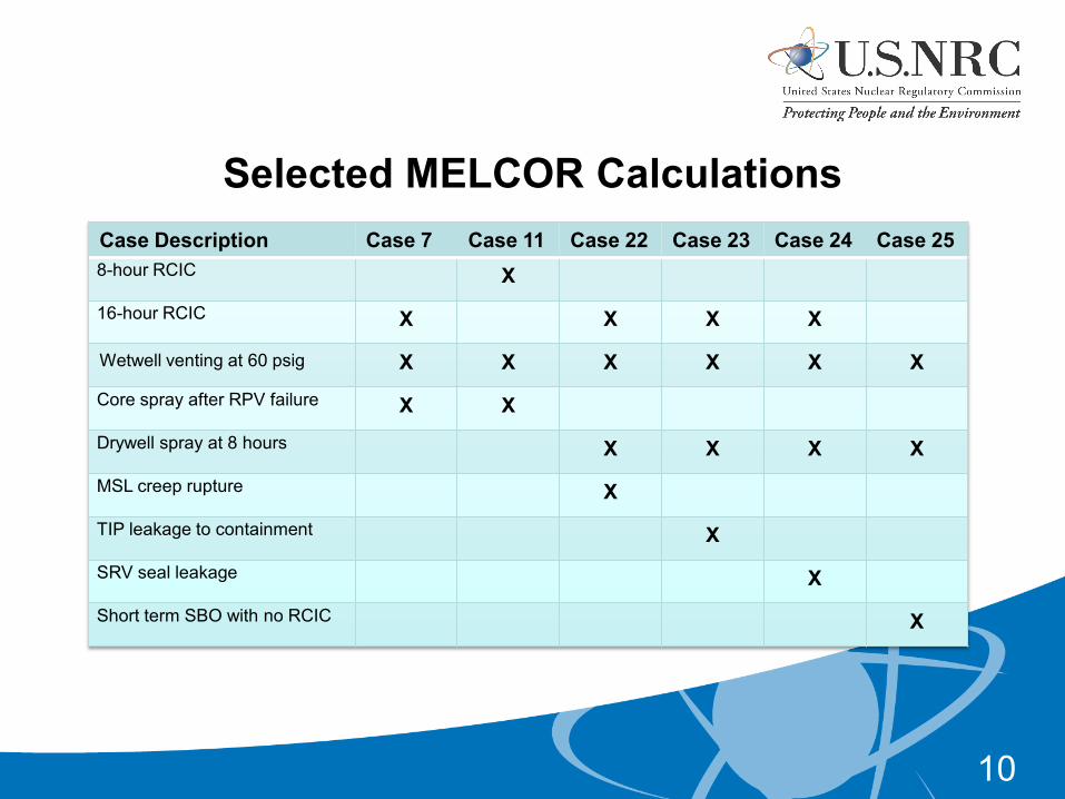
Selected MELCOR Calculations Case Description Case 7 Case 11 Case 22 Case 23 Case 24 Case 25 8-hour RCIC X
16-hour RCIC X X X X
Wetwell venting at 60 psig X X X X X X
Core spray after RPV failure X X
Drywell spray at 8 hours X X X X
MSL creep rupture X
TIP leakage to containment X
SRV seal leakage X
Short term SBO with no RCIC X
10

CV200
CV220FL012
FL020
CV220
FL021
FL903(DW headflange failure)
FL901(Torus Failure)
CV210CV210
CV205
FL014Personnel
access
FL902(DW liner shear)
FL016CRD hyd.
pipe chase
FL015CRD removal
FL904(DW liner
melt-through)
FL017(DW nominal leakage)
FL022(RB-WW vacuum breakerto NE torus corner room)
FL023(RB-WW vacuum breakerto SE torus corner room)
CV201
CV202
FL20
2
FL200
FL910(Wetwell Hard-Pipe ventto atmosphere)
11

12

13

14

15

16

17

18

19
20

21

22

23

24

25

26

27

28

29


Insights from Reviewing Relevant MELCOR and MAAP Results
• RCIC operation and suppression pool temperature • Core melt progression • Cesium release, transport, and revaporization
– MELCOR has mostly Cesium Molybdate, with some Cesium Iodide; very little if any Cesium Hydroxide
– Default MAAP assumes 9% CsI, and 45.5% each of CsOH and Cs2MoO4
31

Sources for Observations
• Peach Bottom SOARCA report • Attachment 5A of SECY-12-0157 • EPRI Technical Report 1026539 and related
MAAP 5 analyses
32
LTSBO Cases Considered
• SOARCA unmitigated LTSBO – 4 hour battery • Case B.1 of EPRI report – 4 hour battery • Case B.8 of EPRI report
– 4 hour battery – 500 gpm flow to drywell spray – Vent cycling and switchover
33

Event Summaries for LTSBO Cases (time in hours)
Event SOARCA Unmitigated
EPRI Unmitigated
EPRI Mitigated
MAAP 5.0.1 Unmitigated
MAAP 5.0.1 Mitigated
RPV Depressurization
1.0 None none 1.0 1.0
Battery Depletion 4.0 4.0 4.0 4.0 4.0
SRV Sticks Open 8.2 6.1 6.1 5.9 5.9
Core Uncovers 8.4 5.2 5.2 6.3 6.3
Core Relocates 10.5 8.8 8.9 9.5 9.6
Vessel Fails 19.7 12.0 12.0 12.1 12.0
Sprays On none none 5.0 none 6.3
Containment Fails 19.9 12.3 none 12.1 none
Wetwell Venting none none 12.1 none 12.3
Drywell Venting none none 17.9 none 26.9
Drywell Sprays Off N/A N/A 49.7 N/A 43.6
34
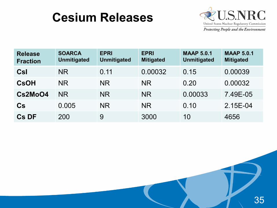
Cesium Releases
Release Fraction
SOARCA Unmitigated
EPRI Unmitigated
EPRI Mitigated
MAAP 5.0.1 Unmitigated
MAAP 5.0.1 Mitigated
CsI NR 0.11 0.00032 0.15 0.00039 CsOH NR NR NR 0.20 0.00032 Cs2MoO4 NR NR NR 0.00033 7.49E-05 Cs 0.005 NR NR 0.10 2.15E-04 Cs DF 200 9 3000 10 4656
35

SOSARCA LTSBO S SOARCA LTSBO RPV Pressure

SOARCA LTSBO RPV Level

SOARCA LTSBO Drywell Pressure

SOARCA LTSBO Suppression Pool Temperature

SOARCA LTSBO Fission Product Releases

MAAP 5.0.1 Water Level in Shroud

MAAP 5.0.1 Hydrogen Produced In-vessel

MAAP 5.0.1 Pressure in RPV

MAAP 5.0.1 Suppression Pool Temperature

MAAP 5.01 RCIC Flow

MAAP 5.01 Drywell Pressure

MAAP 5.01 Cesium Iodide Release Fraction

MAAP 5.01 Cesium Hydroxide Release Fraction

MAAP 5.01 Cesium Molybdate Release Fraction