analyzing a bogie frame behavior by using the · pdf fileanalyzing a bogie frame behavior by...
TRANSCRIPT
U.P.B. Sci. Bull., Series D, Vol. 76, Iss. 4, 2014 ISSN 1454-2358
ANALYZING A BOGIE FRAME BEHAVIOR BY USING THE EXPERIMENTAL METHOD AND ANSYS SIMULATIONS
Yahia Zakaria1
In this paper, the modal simulation in Ansys program was used as a supplementary tool to determine the fatigue strength of a bogie frame. The bogie frame was subjected to a long fatigue experiment to predict its behavior in exploitation. At the end, results gained from the experiment and from the numerical analyzing process were presented and then compared to achieve the final conclusions.
Key words: Simulation, Modal, Bogie, Railway, Ansys.
1. Introduction
The studying of the dynamic behavior and traction performances of locomotives is decisively related to the properties and features of the component parts of these locomotives; because almost all the locomotive parts participate in the traction process. Of these parts we mention: locomotive compartment, bogie, suspension systems and wheel-sets.
The verification of designing quality of these parts has a significant role in the general quality estimation of the locomotive behavior and especially of its dynamic and traction performances. So there is no point of studying the locomotive if one of its parts is weak or unable to pass the tests of the dynamic and static loads resistance and fatigue strength. On the other hand, the researches concerned of analyzing these parts give a better understanding of the dynamic and traction performances of the locomotive. That is gained by the determination of the components which can be modified, by optimizing their shape, size or weight, to reach better traction performances with maintaining, at the same time, their dynamic and static loads resistance and their fatigue resistance. Some of the tests which are performed on the locomotives parts by static analysis are for dynamic and static loads resistance verification. There are also fatigue strength resistance tests which determine the component life time in exploitation before the permanent imperfections, such as cracks and permanent elastic deformation, start to appear.
In this paper, an extended study about the bogie frame strength and its fatigue resistance will be presented. The study will include a static analysis and a
1 PhD Student, University POLITEHNICA of Bucharest, Romania, e-mail: [email protected]
150 Yahia Zakaria
fatigue strength analysis of this bogie frame by using Finite Element Method. The results gained by the simulation process of FEM in Ansys Workbench program will be compared to the experimental results obtained in INMA2 center during the last few months. Before the tests, modal analysis allowed us to predict the natural frequencies of the bogie frame. Thus, resonance, which causes the highest fatigue loads, can be anticipated during the experiment period. After the tests, the comparison between the experimental results and the analytical results will be useful to improve simulation models. Above all, we mention that Ansys has special tools in the static structural analysis that predict the bogie frame life time.
The bogie of a railway vehicle sustains the weight of the car body, controls the wheels sets on straight and curved track and absorbs the vibrations [1]. The bogie consists of a frame, suspension system, wheels-axis sets, braking system, etc [2]. The bogie frame supports heavy static and dynamic loads, such as the vertical loads generated by the body of the vehicle, braking and accelerating loads and twisting loads induced by track twisting. Bogie frames usually weigh from 1 to 2 tons [1].
Increasing the train speed is one of the most important demands for modern railways in order to compete with the alternative transportation systems. Increasing the speed and reducing energy consuming is decisively related to weight decreasing. The accurate studying will lead eventually to better designs of the bogie. Thus, the weight of the bogie can be reduced but with the same structural strength and fatigue resistance. These accurate studies will also allow us to consider a smaller safety factor (about 2.8) [3].
There are several standards for strength evaluation of the conventional bogie frame such as JIS E 4207 [4], UIC 615-4 [5] and others, as it can be seen in [2]. The study should also take the regulations [6],[7],[8] into consideration.
2. Experiment equipment description
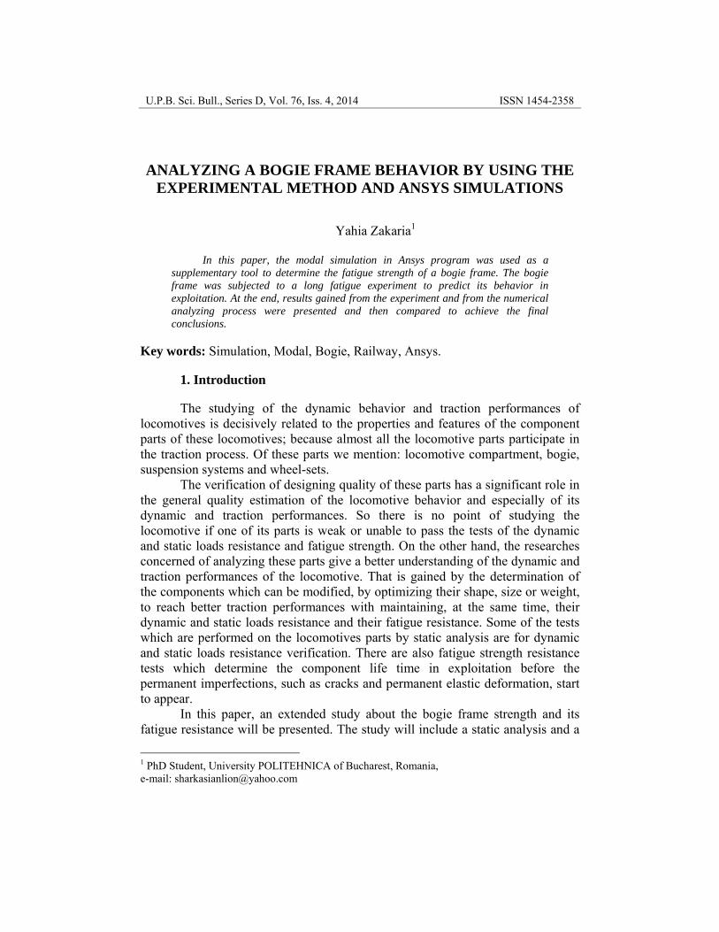
The bogie frame was mounted on a platform which has couples of hydraulic cylinders. Each one of these cylinders generates forces acting on the bogie frame within one specific direction: vertical, longitudinal or transversal (Fig.1). The cylinders are connected to a room containing hydraulic pressure generators (pumps), monitoring and controlling devices and other equipment which assure the quality of the cylinders performance and safety, i.e. leakage detection sensors, general safety equipments, etc. In addition to that room, there is another room called the main room of controlling and monitoring. It contains all the equipments which allow researchers of actuating the cylinders and measuring all the details of the experiment. The main room has three principle processing 2 National Institute of research – development for Machines and installations designed for Agriculture and food industry (www.inma.ro).
Analyzing a bogie frame behavior by using the experimental method and Ansys simulations 151
units connected to three computers which have the main role during the experiment. The first one generates the signals which control the cylinders working routine.
Fig.1 The experiment platform.
The signals determine the force value generated by each cylinder and acting on the bogie frame body and also determine the frequency and working shifts of these vertical, transversal or longitudinal cylinders. This information which is transmitted to the cylinders is previously determined according to the regulation conditions which the experiment is based on, as it was mentioned above. The main regulations in our case are presented in [9] and [10]. The second processing unit measures the actual value of the forces generated by cylinders, its frequency and amplitude by reading the signals coming from sensors situated between the cylinders and bogie frame body. Thus, we can compare these measurements to output signals from the first processing unit to make sure that the cylinders are working properly. The third processing unit receives the signals coming from the deformation sensors which are situated in 16 different critical points of the bogie frame body. By reading and processing these signals we will be able to determine the deformations which happen in the bogie frame during each working cycle. The last procedure is useful for: 1- monitoring the minute changes which occur in the bogie frame when it is subjected to dynamic loads similar to those which take place under the real exploitation conditions; 2- assuring that these deformations are within the elastic deformations limits; 3- discovering any remnants or permanent strains occurred due to fatigue during the experiment. All these units are connected by connection units type μDAQ (Fig.3).

152 Yahia Zakaria
Measuring equipment “Softronic data acquisition system” (Fig.4)
The equipment is a portable construction, type Diplomat, and has the following incorporated elements: 1- DAQ acquisition interface, type USB-30A16 (16 analog channels, 500 kHz sampling, 16 bit resolution) (Fig.2); 2- Support plate for 16 amplifying modules with galvanic isolation type SCMB; 3- External transducers for amplifying modules type SCMB; 4- Piezoelectric acceleration transducers, type 353B32, powered with amplifying modules type SCMB5B48(Fig5, a); 5- Impact hammer (Fig.5, b) with a full-bridge strain gauge powered with amplifying modules type SCMB5B39. This hammer has the following main technical characteristics:
Fig.2 Signals transferring unit
(acquisition interface).
Fig.3 Connection unit between processing units
and computers, type μDAQ. 1- Analog inputs: 16; 2- Digital I/O: 24; 3- Analog outputs: 4; 4- Input voltage: ± 10V; 5- Protection unit against the continuously applied voltage by amplifying modules SCMB: 240 VRMS; 6- Maximum sampling rate: 500 Hz; 7- Resolution: 14 bit for both analog inputs and outputs [11].
Fig.4 Measuring equipment, Softronic Data Acquisition System.
Analyzing a bogie frame behavior by using the experimental method and Ansys simulations 153
3. Experiment description
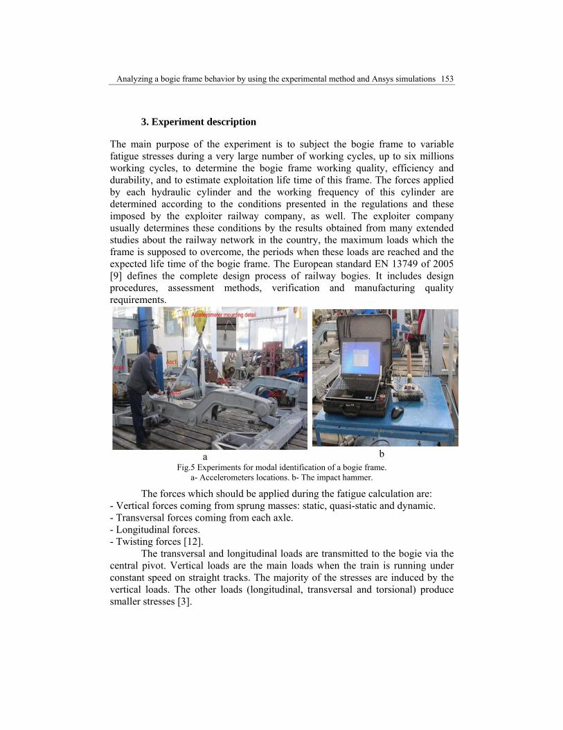
The main purpose of the experiment is to subject the bogie frame to variable fatigue stresses during a very large number of working cycles, up to six millions working cycles, to determine the bogie frame working quality, efficiency and durability, and to estimate exploitation life time of this frame. The forces applied by each hydraulic cylinder and the working frequency of this cylinder are determined according to the conditions presented in the regulations and these imposed by the exploiter railway company, as well. The exploiter company usually determines these conditions by the results obtained from many extended studies about the railway network in the country, the maximum loads which the frame is supposed to overcome, the periods when these loads are reached and the expected life time of the bogie frame. The European standard EN 13749 of 2005 [9] defines the complete design process of railway bogies. It includes design procedures, assessment methods, verification and manufacturing quality requirements.
a b Fig.5 Experiments for modal identification of a bogie frame.
a- Accelerometers locations. b- The impact hammer.
The forces which should be applied during the fatigue calculation are: - Vertical forces coming from sprung masses: static, quasi-static and dynamic. - Transversal forces coming from each axle. - Longitudinal forces. - Twisting forces [12].
The transversal and longitudinal loads are transmitted to the bogie via the central pivot. Vertical loads are the main loads when the train is running under constant speed on straight tracks. The majority of the stresses are induced by the vertical loads. The other loads (longitudinal, transversal and torsional) produce smaller stresses [3].
154 Yahia Zakaria
The norm EN 13749 gives all the possible load configurations in normal operations [12]. It also presents two different approaches for fatigue calculation:
- Endurance limit; - Cumulative damage.
The most frequently used method currently for fatigue assessment of railway structures is the endurance limit approach using nominal stresses with the maximum dynamic and quasi-static loads [13].
The main factors which affect the fatigue strength analysis: - Stress concentrations, which is induced as Kt = the stress concentration factor; - Mechanical properties of material variation between different weld joint zones; - Residual stresses; - Main stress of fatigue cycle; - Presence of defects; - Multi-axial stress; - Variable amplitude loading. The most used fatigue analysis techniques are:
- Nominal stress method; - Hot spot stress method; - Effective notch stress method [12]. The weld geometry has a decisive influence on the fatigue strength of a
welded connection due to its notch effect, such as in the weld toe or weld root. A further possible influence on the fatigue strength performance arises from the residual stresses induced by welding. So the norm EN 12663 should be also taken into consideration [14].
Programs package for modal analysis: On the bases of the theoretical background above presented, it has been
achieved a programs package with a major orientation toward modal analysis of mechanical structures. The package, which is realized in TestPoint programming environment, has a modular conception and includes the following programs:
ModalAch: A module for controlling the excitation and system response during the test.
IdModal: A module for calculating frequency response functions and modal parameters. The frequency response functions are calculated over a selective length of data using some pondering windows. For modal parameters identification, some sophisticated linear and non-linear regressive procedures have been used.
ModalForm: A module for eigen-frequencies assessment, vibration eigen-mode calculating and for graphical illustration of the structure in its eigen-modes. The program reads data from the files achieved with IdModal program [11].
Experiment stages:
1- Before mounting the bogie frame on the experiment platform, some preliminary verifications should be executed: a- Resonance test performed with the impact hammer and acceleration sensors placed on
Analyzing a bogie frame behavior by using the experimental method and Ansys simulations 155
the bogie body frame (Fig.5), b- Ultrasonic test and c- measuring the bogie frame initial dimensions with a laser station;
2- Mounting the measuring electro-conductors on the bogie frame body in 16 specific points to measure the strains and deformations which occur in these points. 7 points on each side beam and one in the middle of each lateral beam;
3- The equilibrium of measuring system and experiment platform; 4- Static structural verification by applying exceptional static loads
created by the hydraulic pistons; 5- Static structural verification by applying the normal loads which occur
during the exploitation; 6- Fatigue resistance verification which includes three sub-stages:
a- In the 1st step a number of 6*106 cycles will be performed with loads calculated according to [10] and [6];
b- In the 2nd step a number of 2*106 cycles will be performed with loads increased by 20% in comparison with those of the 1st stage;
c- In the 3rd step a number of 2*106 cycles will be performed with loads increased by 40% in comparison with those of the 1st stage.
- Every 1*106 cycles a checking procedure is performed to assure that measuring equipments are still equalized, and then a visual and ultrasonic verification is performed to assure that the bogie frame does not suffer of any cracks. In the 1st two stages, it is not allowed for any crack to appear in the bogie frame body, while in the last stage, there is a tolerance in the appearing of small cracks which wouldn’t need urgent repairing if they had appeared during the exploitation [9], [15].
4. Using the modern techniques and simulation processes
Modal simulation: The use of finite elements method for designing, simulating and
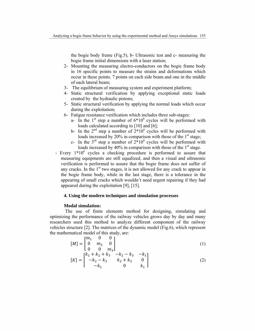
optimizing the performance of the railway vehicles grows day by day and many researchers used this method to analyze different component of the railway vehicles structure [2]. The matrices of the dynamic model (Fig.6), which represent the mathematical model of this study, are:
0 00 00 0
(1)
00
(2)

156 Yahia Zakaria
00
(3)
0 (4) (5)
The original equations of motion are described in [16].
For a free vibration analysis, the natural circular frequencies and mode shapes are calculated in Ansys Workbench from the following equation:
0 (6) With adopting the following assumptions: • The stiffness matrix [K] and the mass matrix [M] are constant • Linear elastic material behavior is assumed • Small deflection theory is used, and no nonlinearities included • [C] is not present, so damping is not included • {f} is not present, so no excitation of the structure is assumed • The structure is considered totally free and unconstrained • Mode shapes are relative values, not absolute [17]. Because of the large volume of data required for creating accurate body
models close to the real ones, usually simplified models can be used. We calculate the natural frequencies before the tests to make sure that the frequency of the exciting forces is not close to the natural frequencies of the system and that the resonance will not occur [2].
5. Simulation process stages
Every simulation process should contain the following main stages: 1- Preprocessing:
Fig.6 The dynamic model of the locomotive.
Where: - y: wheel-set displacement; - x1: bogie frame displacement;
- x2: locomotive compartment displacement
Analyzing a bogie frame behavior by using the experimental method and Ansys simulations 157
2- Processing: 3- Post processing: An extended explanation of these stages is also presented in [18]. The mentioned stages are the general stages which should be included in
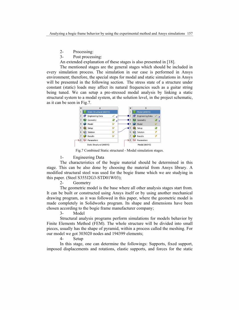
every simulation process. The simulation in our case is performed in Ansys environment; therefore, the special steps for modal and static simulations in Ansys will be presented in the following section. The stress state of a structure under constant (static) loads may affect its natural frequencies such as a guitar string being tuned. We can setup a pre-stressed modal analysis by linking a static structural system to a modal system, at the solution level, in the project schematic, as it can be seen in Fig.7.
Fig.7 Combined Static structural - Modal simulation stages.
1- Engineering Data The characteristics of the bogie material should be determined in this
stage. This can be also done by choosing the material from Ansys library. A modified structural steel was used for the bogie frame which we are studying in this paper. (Steel S355J2G3-STD01W03);
2- Geometry The geometric model is the base where all other analysis stages start from.
It can be built or constructed using Ansys itself or by using another mechanical drawing program, as it was followed in this paper, where the geometric model is made completely in Solidworks program. Its shape and dimensions have been chosen according to the bogie frame manufacturer company;
3- Model Structural analysis programs perform simulations for models behavior by
Finite Elements Method (FEM). The whole structure will be divided into small pieces, usually has the shape of pyramid, within a process called the meshing. For our model we got 303020 nodes and 194399 elements;
4- Setup In this stage, one can determine the followings: Supports, fixed support,
imposed displacements and rotations, elastic supports, and forces for the static
158 Yahia Zakaria
analysis, and the maximum number of the modes for the modal analysis. These and other boundary conditions are described in [6],[10],[18];
5- Solution This stage is related to the system properties - where the computer
properties will limit the number of mesh nodes and affect solving time. For the cases with very fine meshing and huge number of mesh nodes, many systems will fail to accomplish the calculations. Thus, the better properties of the system will lead to more accurate results. System properties are introduced in [18];
6- Results In this stage the user chooses the type of results he needs to visualize. The
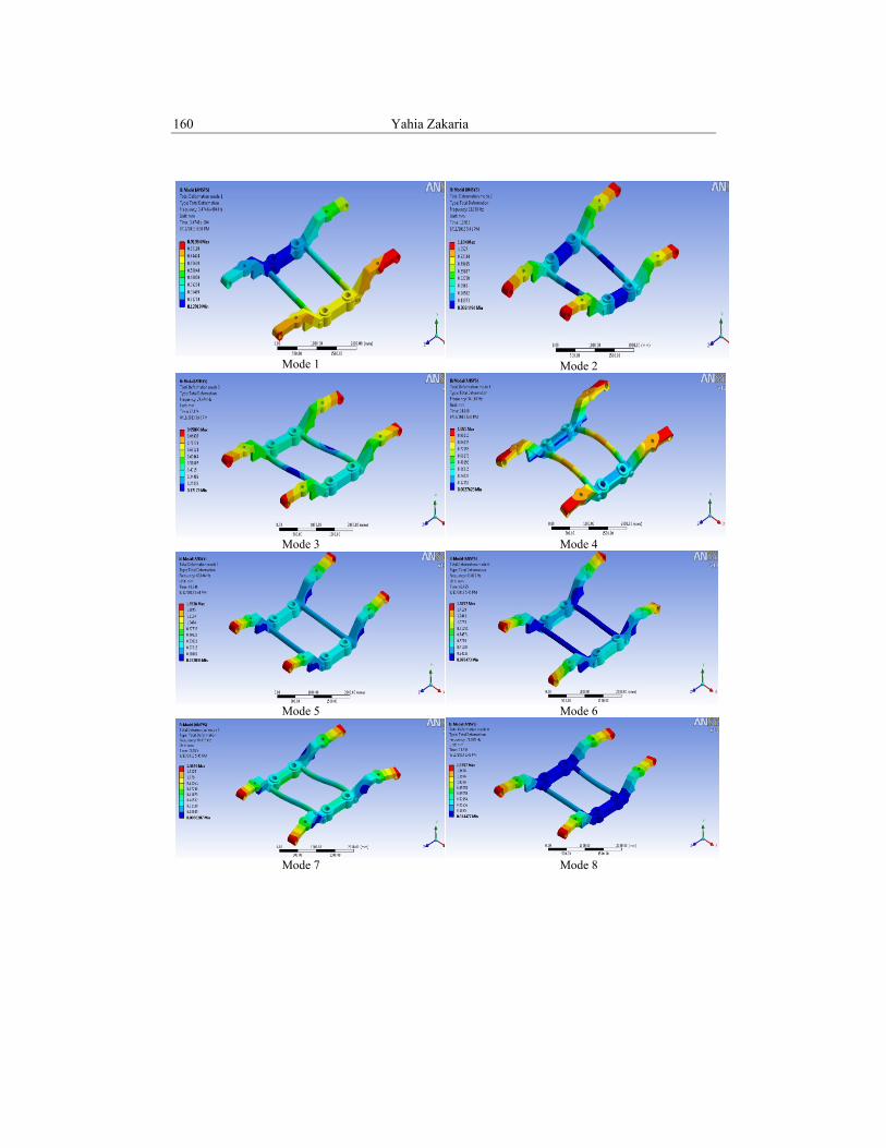
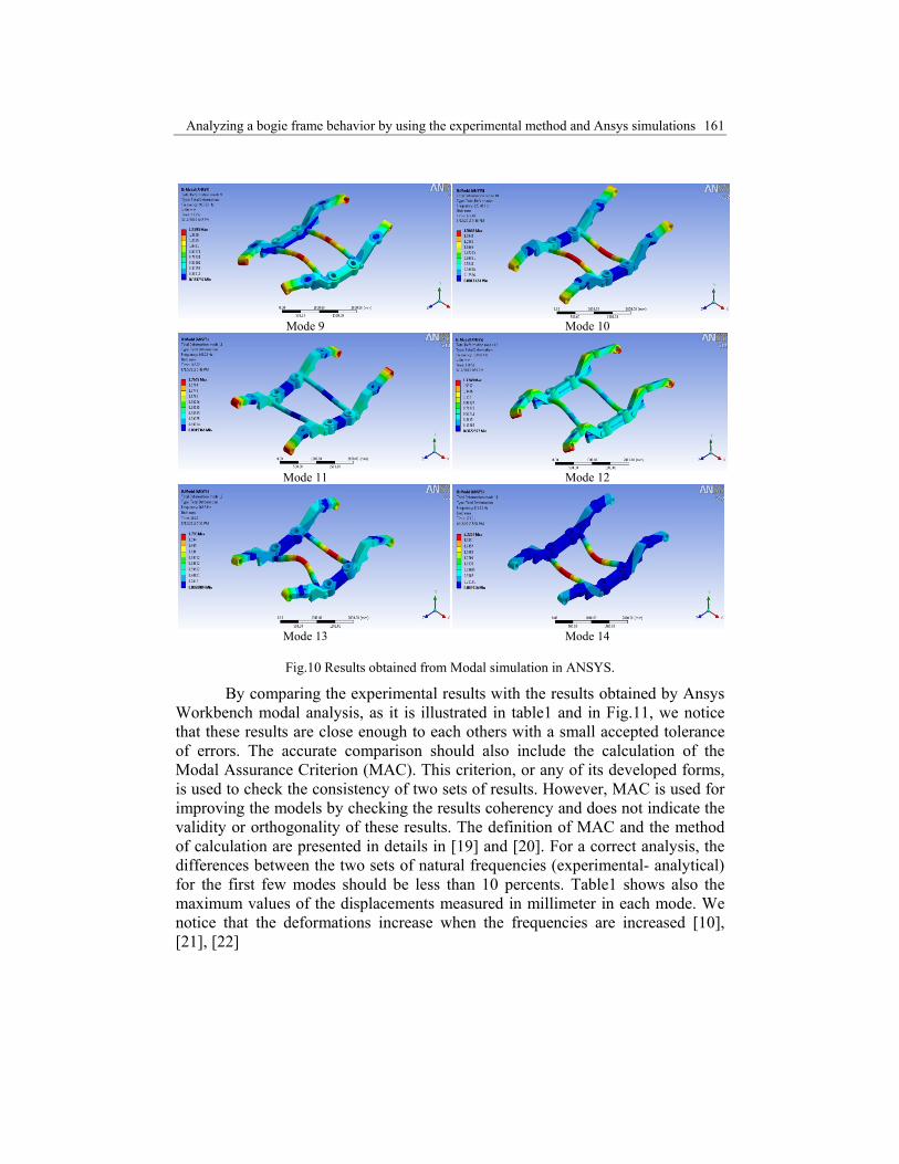
exaggerated views of the deformations occurred in the bogie frame for each mode (mode shapes) are presented in Fig.10. More details about these stages are presented in [10], [17] and [18].
6. Results
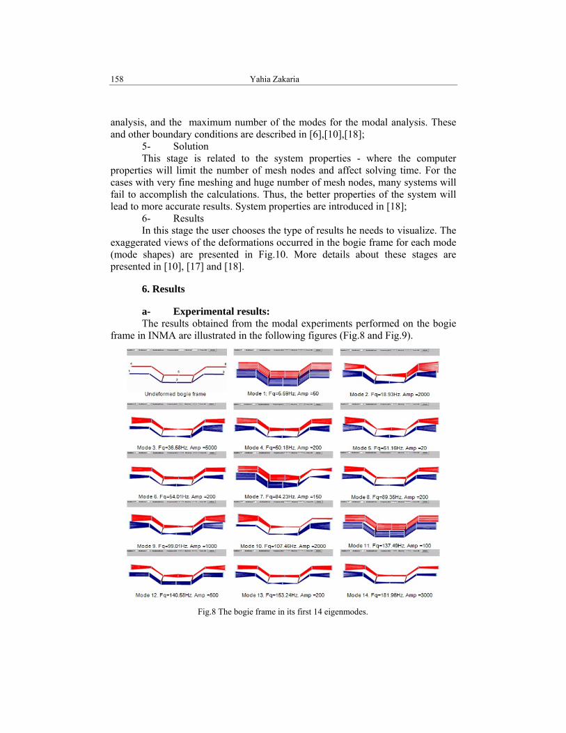
a- Experimental results: The results obtained from the modal experiments performed on the bogie
frame in INMA are illustrated in the following figures (Fig.8 and Fig.9).
Fig.8 The bogie frame in its first 14 eigenmodes.

Analyzing a bogie frame behavior by using the experimental method and Ansys simulations 159
At the end of the 6 million cycles of fatigue testing, dimensional measurements of the frame were performed with a laser station to make sure that the frame structure does not suffer of permanent deformations. An ultrasonic control was also effectuated and no cracks in the welded joints or in the whole frame structure were found.
The analysis of mechanical stresses, dimensional measurements and ultrasonic checking have not showed any major permanent deformation or structure modification in the bogie frame. The modal analysis applied at the start of the static tests and after 6 millions of fatigue loads cycles have not revealed a notable change in eigen-frequencies or any appearance of additional eigen-modes.
It is necessary to continue the application of modal identification tests for 2 millions more of fatigue test cycles with loads amplified with factor 1.2, respectively, for 2 millions more of cycles with loads amplified by factor 1.4, compared with the nominal fatigue loads [11].
Fig.9 Stages of bogie frame deformations in the 2nd, 4th and 5th eigenmodes.
b- Results gained by using Ansys:
In the following figures (Fig.10, Mode 1 to 14), we present the results obtained from the modal simulation performed in Ansys. The figures show the deformations which occur in each mode. The deformations which appear in the figures are exaggerated to illustrate how the bogie frame is affected in each mode.
160 Yahia Zakaria
Mode 1 Mode 2
Mode 3 Mode 4
Mode 5 Mode 6
Mode 7 Mode 8
Analyzing a bogie frame behavior by using the experimental method and Ansys simulations 161
Mode 9 Mode 10
Mode 11
Mode 12
Mode 13
Mode 14
Fig.10 Results obtained from Modal simulation in ANSYS.
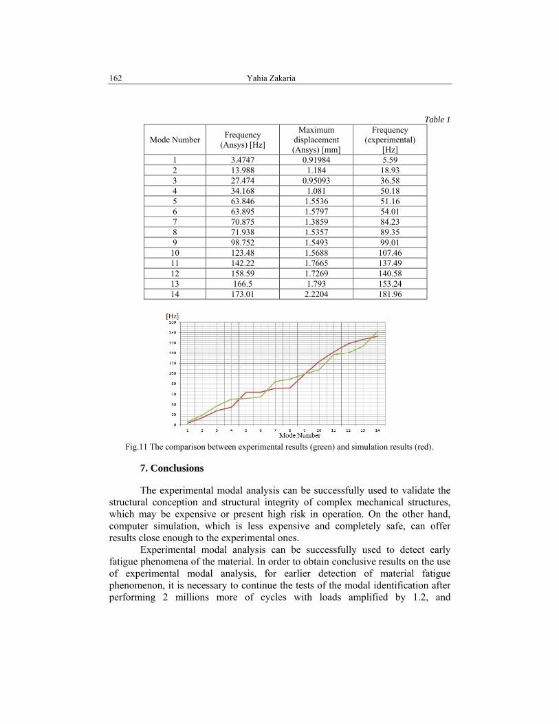
By comparing the experimental results with the results obtained by Ansys Workbench modal analysis, as it is illustrated in table1 and in Fig.11, we notice that these results are close enough to each others with a small accepted tolerance of errors. The accurate comparison should also include the calculation of the Modal Assurance Criterion (MAC). This criterion, or any of its developed forms, is used to check the consistency of two sets of results. However, MAC is used for improving the models by checking the results coherency and does not indicate the validity or orthogonality of these results. The definition of MAC and the method of calculation are presented in details in [19] and [20]. For a correct analysis, the differences between the two sets of natural frequencies (experimental- analytical) for the first few modes should be less than 10 percents. Table1 shows also the maximum values of the displacements measured in millimeter in each mode. We notice that the deformations increase when the frequencies are increased [10], [21], [22]
162 Yahia Zakaria
Table 1
Mode Number Frequency (Ansys) [Hz]
Maximum displacement (Ansys) [mm]
Frequency (experimental)
[Hz] 1 3.4747 0.91984 5.59 2 13.988 1.184 18.93 3 27.474 0.95093 36.58 4 34.168 1.081 50.18 5 63.846 1.5536 51.16 6 63.895 1.5797 54.01 7 70.875 1.3859 84.23 8 71.938 1.5357 89.35 9 98.752 1.5493 99.01 10 123.48 1.5688 107.46 11 142.22 1.7665 137.49 12 158.59 1.7269 140.58 13 166.5 1.793 153.24 14 173.01 2.2204 181.96
Fig.11 The comparison between experimental results (green) and simulation results (red).
7. Conclusions
The experimental modal analysis can be successfully used to validate the structural conception and structural integrity of complex mechanical structures, which may be expensive or present high risk in operation. On the other hand, computer simulation, which is less expensive and completely safe, can offer results close enough to the experimental ones.
Experimental modal analysis can be successfully used to detect early fatigue phenomena of the material. In order to obtain conclusive results on the use of experimental modal analysis, for earlier detection of material fatigue phenomenon, it is necessary to continue the tests of the modal identification after performing 2 millions more of cycles with loads amplified by 1.2, and
Analyzing a bogie frame behavior by using the experimental method and Ansys simulations 163
respectively, 2 millions of cycles with loads amplified by 1.4, in comparison with the nominal fatigue loads according to the European standard EN 13749.
Using fatigue tools in Ansys static structural simulation showed that the bogie frame can resist 6*106 cycles without any cracks or imperfections, and it has a safety factor up to 7 under the normal static loads. Under the dynamic and exceptional loads the safety factor will be up to 2. By comparing the results obtained from the experiment and those obtained from Ansys, we notice that Ansys results have confirmed the experimental results. Although there were a few differences between these two groups of results, they are generally coincident and assure that this bogie frame has passed the fatigue tests imposed by CFR3 according to EN 13749. The differences between the experimental results and those obtained from Ansys are small and don’t exceed the accepted range of tolerance in errors. These errors, however, are produced because of the following: 1- The simplification of the geometric model in comparison with the real one; 2- The limited abilities of the used computer; 3- The ideal conditions and mathematical model used by Ansys to obtain the results. Drawing a high-detailed geometric model will make the results closer to reality, but it will complicate the simulation and will increase the simulation time and costs. Using a computer with a high performance will increase the simulation costs, but these costs are minute and neglected if they are compared to the costs of the experiment. Ansys has the ability to match two or more simulation processes together to take all the real conditions into consideration. However, boundary conditions widely affect the simulation results and they should be carefully chosen. The correlation between the two sets of results of the modal analysis has been performed using MAC. This criterion helps us to check results consistency and to improve models of the modal analysis in the future simulations. The items which will require research work, in addition to the norm EN13749, are mainly two. The first one is the method of using FEM simulation and the fatigue assessment in the welded joints. The second one is the definition of a standard calculation methodology for the evaluation of the fatigue strength in case of multi-axial stresses [12].
R E F E R E N C E S
[1] Jung Seok Kim, Hyuk Jin Yoon, Structural behaviors of GFRP composite bogie frame for urban subway trains under critical load conditions, Elsevier, ICM11, Procedia Engineering 10, 2011, pp.2375-2380.
[2] Mohammad Zehsaz, Farid Vakili Tahami, Ali Ziaei Asl, Fatemeh Ahmadian, Effect of increasing speed on stress of biaxial bogie frames, Engineering, Scientific Research, 2011, pp.276-284.
[3] Jinping Hou, George Jeronimidis, A novel bogie design made of glass fiber reinforced plastic, Elsevier, Materials and Design, 2011, pp.1-7.
3 The National Romanian railways (Căile Ferate Române)
164 Yahia Zakaria
[4] JIS E 4207-2004, Truck frames for railway rolling stock – General rules for design, June 2004. [5] UIC 615-4, Motive power units – bogies and running gear – bogie frame structure strength
tests, 2nd Ed., February 2003. [6] UIC 515-4, Passenger rolling stock – trailer bogies – running gear – bogie frame structure
strength test, 1st Ed.1.1.93. [7] UIC 566, Loadings of coach bodies and their components, 3rd Ed.1.1.90, Addenda and
Amendment. [8] UIC 518, Testing and approval of railway vehicles from the point of view of their dynamic
behavior – safety – track fatigue – ride quality, 3rd Ed., October 2005. [9] UNI EN 13749, Railway applications, wheel sets and bogies, Methods of specifying the
structural requirements of bogies frames, Sep.2005. [10] I. Manea, Analiza modală experimentală (Experimental modal analysis), Editura
Universitarea Craiova, 2006. [11] I. Manea, I. Matache, A. Muscalu, C. Persu, I. Voicea, Research for modal analysis utilization
as a tool for fatigue and structural change assessment of mechanical structures, INMATEH, Vol.4, No.3, Bucharest, 2013. pp:17-26
[12] A. Cera, G. Mancini, V. Leonardi, L. Bertini, Analysis of methodologies for fatigue calculation for railway bogie frames, WCRR, Seoul, May 18-22, 2008.
[13] M. Kassner, Fatigue strength analysis of a welded railway vehicle structure by different methods, International journal of fatigue, Elsevier, 2012, pp.103-111.
[14] A. Esderts, J. Willen, M. Kassner, Fatigue strength analysis of welded joints in closed steel sections in rail vehicles, International journal of fatigue, Elsevier, 2012, pp.112-121.
[15] Vojkan J. Lucanin, Coran Z. Simic, Dragan D. Milkovic, Nenad Lj Cupric, Snezana D. Golubovic, Calculated and experimental analysis of cause of the appearance of cracks in the running bogie frame of multiple units of Serbian railways, Engineering failure analysis, Elsevier, 2009, pp.236-248.
[16] Ioan Sebesan, Dynamics of railway vehicles, (Dinamica vehiculelor feroviare), Matrixrom, Bucharest, 2011.
[17] Ansys Inc., Workbench-mechanical 12 introduction, chapter 5 vibration analysis, Feb.2009. [18] Ioan Sebesan, Yahia Zakaria, A static wheel-rail interaction analysis by using ANSYS
program, Sinteze de mecanica teoretica si aplicata (Theoretical and applied mechanical sintheses) MatrixRom, Bucharest Vol.4, Nr.2, 2013, pp.77-90 .
[19] Mirsolav Pastor, Michal Binda, Tomas Harcarik, Modal assurance criterion, Procedia engineering, Elsevier, 2012, pp.543-548
[20] Randall J. Allemang, The modal assurance criterion – Twenty years of use and abuse, Sound and vibration, University of Cincinnati, Cincinnati, Ohio, August 2003, pp.14-21
[21] ORE B12/RP60, Regulations for proof tests and maximum permissible stresses, 2nd Ed. [22] EN 1993: (Eurocode 3), Design of steel structures.