analyzing bpel processes using petri nets - tu/ewvdaalst/publications/p263.pdf · analyzing bpel...
TRANSCRIPT
Analyzing BPEL processes using Petri nets
H.M.W. Verbeek, W.M.P. van der Aalst
Department of Technology Management, Eindhoven University of TechnologyP.O. Box 513, NL-5600 MB, Eindhoven, The Netherlands.
{h.m.w.verbeek,w.m.p.v.d.aalst}@tm.tue.nl
Abstract. Some years ago, BEA, IBM, Microsoft, SAP AG, and SiebelSystems teamed up and proposed the Business Process Execution Lan-guage for Web Services (BPEL or BPEL4WS) for application integrationwithin and across organizational boundaries. By now, BPEL has becomethe de facto standard in this Web services composition arena. However,little effort has been dedicated so far concerning the verification of themodeled business processes. For example, there is no support to detectpossible deadlocks, or to detect parts of the process that are not viable.For so-called WF-nets (workflow nets), techniques and tools exist whichmake it possible to detect such anomalies. Therefore, we could detectthese anomalies in a BPEL process model provided that we can suc-cessfully map this model onto a WF-net. This papers describes a firstattempt to map a BPEL process model onto a WF-net. Although notall BPEL constructs have been mapped yet, the results seem promising,as we are able to map typical examples from the BPEL 1.1 specificationonto WF-nets.
1 Introduction
Web Services are rapidly emerging as the principal paradigm for architecting andimplementing business collaborations within and across organizational bound-aries. According to this paradigm, the functionalities provided by business ap-plications are encapsulated within web services: software components describedat a semantical level, which can be invoked by application programs or by otherservices through a stack of Internet standards including HTTP, XML, SOAP,WSDL, and UDDI [7]. Once deployed, web services provided by various orga-nizations can be inter-connected in order to implement business collaborations,leading to composite web services.
Business collaborations require long-running interactions driven by explicitprocess models [4]. Accordingly, it is a natural choice to capture the logic ofa composite web service using business process modeling languages tailored forweb services. Many such languages have recently emerged, including WSCI [21],BPML [6], BPEL(4WS) [8], BPSS [18], and XPDL [22], with little effort beingdedicated to the verification of these explicit process models. Questions such as:
– Can an instance of a Web service can always be completed successfully?– Is completion always clean, that is, is nothing left behind upon completion?
– Are all parts of the Web service viable, that is, are there no dead parts?
are left unanswered.Existing powerful Petri-net-based techniques could be used to verify the pro-
cess models by answering the aforementioned questions, provided that it is pos-sible to successfully map the BPEL process model onto a WF-net (a class ofPetri nets). In this paper, we make a first attempt to map BPEL process modelsonto WF-nets. The reason for selecting BPEL is that is the most widely knownand used, and has become the de facto standard for this kind of languages.
The remainder of this paper is organized as follows. Section 2 introduces, ina nutshell, both BPEL and WF-nets. Section 3 introduces the current mapping.Section 4 discusses the results of this mapping on some example BPEL processmodels found in [5]. Next, Section 5 shows that for an small erroneous examplethe behavior of the Oracle BPEL Process Manager [16] is consistent with thebehavior of the mapped WF-net. Section 6 discusses related work. Finally, weconclude the paper.
2 Preliminaries
2.1 BPEL
BPEL, also known as BEPL4WS, builds on IBMs WSFL (Web Services FlowLanguage) and Microsofts XLANG (Web Services for Business Process Design).Accordingly, it combines the features of a block structured process language(XLANG) with those of a graph-based process language (WSFL). BPEL is in-tended for modeling two types of processes: executable and abstract processes.An abstract process is a business protocol specifying the message exchange be-havior between different parties without revealing the internal behavior of anyof them. An executable process specifies the execution order between a numberof constituent activities, the partners involved, the messages exchanged betweenthese partners, and the fault and exception handling mechanisms.
A BPEL process specification is a kind of flow-chart. Each element in theprocess is called an activity. An activity is either primitive or structured. Theprimitive activity types are:
invoke to invoke an operation of a web service described in WSDL;receive to wait for a message from an external source;reply to reply to an external source;wait to remain idle for some time;assign to copy data from one data container to another;throw to indicate errors in the execution;terminate to terminate the entire service instance; andempty to do nothing.
To enable the representation of complex structures, the following structuredactivities are provided:
sequence for defining an execution order;switch for conditional routing;while for looping;pick for race conditions based on timing or external triggers;flow for parallel routing; andscope for grouping activities to be treated by the same fault-handler.
Structured activities can be nested. Given a set of activities contained within thesame flow, the execution order can further be controlled through (control) links,which allow the definition of dependencies between two activities: the targetactivity may only start when the source activity has ended. Activities can beconnected through links to form directed acyclic graphs.
2.2 WF-nets
We will attempt to map a BPEL process model onto a class of Petri nets knownas WF-nets (WorkFlow nets) [1–3], because for this class of nets a soundnessproperty has been defined [1, 14] and a verification tool (Woflan [19, 20]) exists.Basically, a WF-net is a classical Petri net with three additional requirements:
1. There exists a single source place, usually denoted i.2. There exists a single sink place, usually denoted o.3. For every node (place or transition) there exists a path from i to o which
covers the node.
A token in place i denotes a case (an instance of a Web service, in BPEL terms)that is ready to be started, whereas a token in place o denotes a case that hasbeen completed. The third requirement enforces that every node contributes tothe completion of instances.
A WF-net is called sound if and only if it satisfies the following three require-ments:
1. For every possible instance, completion is possible, that is, a token can beput into place o).
2. For every completed instance, completion is clean, that is, if o contains atoken then o is the only place containing a token.
3. Every node is viable, that is, every node can be activated.
Using existing Petri-net-based techniques, a tool like Woflan can decide sound-ness of any WF-net, and report any anomalies back to the modeler. Using thisreport, the modeler can then correct the model.
3 Mapping
In this section, we will map the structured activities onto Petri nets, except forthe scope activity. Furthermore, our mapping will provide support for controllinks. We have used [5] as basis for our mappings.

Note that an activity is not necessarily mapped onto a WF-net, as most of theactivities are mapped onto a Petri net that contains multiple source places andmultiple sink places. However, the top-most activity, including all its containedactivities, will be mapped onto a WF-net, and this WF-net can be verified forsoundness.
3.1 Activities
Any BPEL activity can have a name, a join condition, a join-fault setting, anumber of sources, and a number of targets. The join condition is a Booleanexpression over the activity’s targets. The activity can only be started if the joincondition has evaluated to “true”. The join-fault setting describes what shouldhappen in case the join condition evaluates to “false”. If the join condition isset to “yes”, then the activity is simply skipped; if set to “no”, then a join faultwill be thrown which needs to be caught by some element up in the hierarchy.As long as the exception has not been caught, activities will be aborted. For hispaper, we assume this setting to be “yes”. The sources are the outgoing linksthat will be traversed if this activity has either been completed or skipped. Ifskipped, the corresponding link will have a negative status. If completed, then anoptional transition condition determines its status. The targets are the incominglinks that need to be traversed before this activity can start. A traversed targetcan have either a positive or a negative status.
falsetargets
falsesources
start end
sf
st
ef
et
started completed
truetargets
truesources
Activity
skip
Fig. 1. Mapping for an activity.
Figure 1 shows how we map this onto a Petri net fragment. The place startcontains a token if the hierarchical structure enables this activity. For everytarget, a true place and a false place are present. If the corresponding link hasbeen traversed, either the true place contains a token (indicating that the linkhas a positive status) or the false place contains a token (indicating that the linkhas a negative status). The join condition is mapped onto a set of st (start true)transitions: One st transition for every valid combination of targets. For everyinvalid combination of targets, a sf (start false) transition is present. If the set ofpositive targets is valid, that is, if the join condition evaluates to “true”, then theactivity is started. After the activity has been completed, the corresponding et(end true) transition forwards control to both the next activity in the hierarchicalstructure (through place end) and to the sources. If the set of positive targets is

invalid, the corresponding sf transition forwards control to the skip place, afterwhich the ef (end false) transition forwards control to both the next activity inthe hierarchical structure (through place end) and to the sources. Please notethat an activity forwards a positive control to its sources if it was completed, andthat it forwards a negative control (for dead path elimination) if it was skipped.
start endet
started completed
st Activity
Fig. 2. Mapping for a link-less activity.
Figure 2 shows how we map an activity without sources or targets. Becauseany source or target must refer to some link defined in some flow activity higherup in the hierarchy, the top activity in the hierarchy cannot have sources ortargets. Thus, this top activity will have exactly one source place (start) andexactly one sink place (end).
3.2 Links
falsesource
truetarget
truesource
falsetarget
tf
tt
ff
Fig. 3. Mapping for a link.
Figure 3 shows how we map a link onto a Petri net fragment. If the sourceactivity was skipped, then place false source contains a token, and we simply haveto pass this negative control on (dead path elimination) to the target activitythrough the place false target. If the source activity was completed, then placetrue source contains a token, and the transition condition determines whethera positive control or a negative control needs to be forwarded. If the transitioncondition evaluates to “true”, then a positive control is forwarded through placetrue target (that is, transition tt fires), otherwise a negative control is forwarded(that is, transition tf fires). Note that transition tf (true false) is absent if notransition condition is given for this link.
In the remainder of this section, we will abstract from links as much as possi-ble. Instead we will focus on the core of the activity, that is, the part between the

places “started” and “completed”. As a result, we will show places like “start”and “true sources” only if they are relevant for the activity at hand.
3.3 Basic Activities
b atrue
targets
falsesourcesstart
end
c
started completed
Fig. 4. Mapping for a basic activity. Note that standard connections shown in Figure 1have been omitted.
A basic activity (like, for example, invoke, receive, and reply) does not containany other activity. A basic activity can be completed, aborted (by not catching athrown exception), or rolled back (using a compensation handler). Figure 4 showshow we map this onto a Petri net fragment. Transition c models the completionof the activity, transition a its abortion, and transition b its rolling back. Notethat a roll back will set the status of all its incoming links to positive. Because theactivity had been started, its join condition must have been evaluated to “true”,and we assume that a join condition will evaluate to “true” if all incoming linkshave a positive status. Therefore, it seems safe to roll back to a state where allincoming links have a positive status.
3.4 Sequence Activities
started completed
Activity A Activity B Activity C
Fig. 5. Mapping for a sequence activity.
A sequence activity contains ordered set of activities, and takes care of executingthese contained activities in the given order. Figure 5 shows how this can be(trivially) mapped onto a Petri net fragment.
Although it is not shown in Figure 5 (and in many figures to come), it ispossible that links exists between enclosed activities. For example, there couldbe links from Activity B to Activity C, from Activity A to Activity C, and therecould be even links to and from activities outside the sequence. Figures 1 and
3 show how such links are mapped onto Petri net fragments, which extend thePetri net fragment resulting from Figure 5.
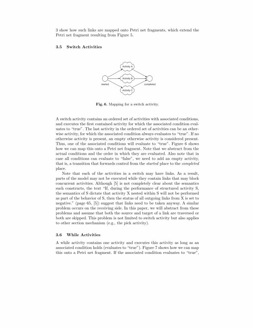
3.5 Switch Activities
started completed
Activity A
Activity B
Activity C
Fig. 6. Mapping for a switch activity.
A switch activity contains an ordered set of activities with associated conditions,and executes the first contained activity for which the associated condition eval-uates to “true”. The last activity in the ordered set of activities can be an other-wise activity, for which the associated condition always evaluates to “true”. If nootherwise activity is present, an empty otherwise activity is considered present.Thus, one of the associated conditions will evaluate to “true”. Figure 6 showshow we can map this onto a Petri net fragment. Note that we abstract from theactual conditions and the order in which they are evaluated. Also note that incase all conditions can evaluate to “false”, we need to add an empty activity,that is, a transition that forwards control from the started place to the completedplace.
Note that each of the activities in a switch may have links. As a result,parts of the model may not be executed while they contain links that may blockconcurrent activities. Although [5] is not completely clear about the semanticssuch constructs, the text “If, during the performance of structured activity S,the semantics of S dictate that activity X nested within S will not be performedas part of the behavior of S, then the status of all outgoing links from X is set tonegative.” (page 65, [5]) suggest that links need to be taken anyway. A similarproblem occurs on the receiving side. In this paper, we will abstract from theseproblems and assume that both the source and target of a link are traversed orboth are skipped. This problem is not limited to switch activity but also appliesto other section mechanism (e.g., the pick activity).
3.6 While Activities
A while activity contains one activity and executes this activity as long as anassociated condition holds (evaluates to “true”). Figure 7 shows how we can mapthis onto a Petri net fragment. If the associated condition evaluates to “true”,

ct
cf
started
completed
Activity A
Fig. 7. Mapping for a while activity.
then transition ct (condition true) will forward control to the contained activityA. When activity A completes, it will put the control back. If the associated con-dition evaluates to “false”, transition cf (condition false) will forward the controlto the completed place, indicating that this while activity has now completed.
3.7 Pick Activities
event A
event B
started completed
Activity A
Activity B
Activity C
Fig. 8. Mapping for a pick activity.
A pick activity contains a (non-zero) number of onMessage elements and a (pos-sibly zero) number of onAlarm elements. Each onMessage element contains areference to some event, a possible set of correlations, and an activity. As soonas the event has occurred, the pick activity can start the corresponding activity.Each onAlarm element contains either a absolute time or a relative time, andan activity. As soon as the absolute time has been reached or the relative timehas been passed, the pick activity can start the corresponding activity. A pickactivity starts only one activity. After it has started an activity, a pick activitywaits until that activity has completed. A pick activity completes as soon as itsstarted activity completes. Figure 8 shows how we can map this onto a Petri netfragment.
3.8 Flow Activities
A flow activity contains a number of links and a (non-zero) number of activi-ties. In the hierarchical activity structure, all contained activities are enabled in

as aj
started completed
Activity A
Activity B
Activity C
Fig. 9. Mapping for a flow activity.
parallel. However, due to the link structure, some activities might not be able tostart immediately. A flow activity completes as soon as all its contained activitieshave completed. Figure 9 shows how we can map the hierarchical structure ontoa Petri net fragment, for the link structure we refer to Figure 1 and Figure 3.In Figure 9, transition as (AND-split) enables all activities, and transition aj(AND-join) completes the flow activity.
3.9 A Reduction
skip
falsetargets
falsesources
start end
sf
st
ef
ettrue
targetstruesources
Fig. 10. Mapping for an activity that does not contain a source, target, or pick.
It is straightforward to check, that most of the activities can only lead to prob-lems if they contain sources or targets. The only exception is the pick activity,which may block because it lacks any of the necessary events. Thus, if any activ-ity does not contain any source, target, or pick, then that activity can cause noproblems. Hence, we can use the more simple mapping as shown in Figure 10.
4 Examples
The following examples show how the structure of a BPEL process model ismapped onto a WF-net. The examples are all taken (descriptions have beencopied in) from the section on structured activities of the BPEL 1.1 specification[5] and, therefore, serve as a nice illustration of the mappings presented in thispaper.

4.1 Flow Graph Example
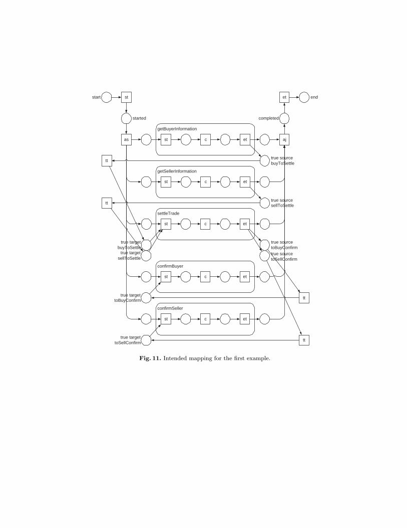
Descriptions In the following example, the activities with the names getBuyer-Information, getSellerInformation, settleTrade, confirmBuyer, and confirmSellerare nodes of a graph defined through the flow activity. The following links aredefined:
– The link named buyToSettle starts at getBuyerInformation (specified throughthe corresponding source element nested in getBuyerInformation) and endsat settleTrade (specified through the corresponding target element nested insettleTrade).
– The link named sellToSettle starts at getSellerInformation and ends at set-tleTrade.
– The link named toBuyConfirm starts at settleTrade and ends at confirm-Buyer.
– The link named toSellConfirm starts at settleTrade and ends at confirm-Seller.
Based on the graph structure defined by the flow, the activities getBuy-erInformation and getSellerInformation can run concurrently. The settleTradeactivity is not performed before both of these activities are completed. AftersettleTrade completes the two activities, confirmBuyer and confirmSeller areperformed concurrently again.
<flow suppressJoinFailure="yes"><links><link name="buyToSettle"/><link name="sellToSettle"/><link name="toBuyConfirm"/><link name="toSellConfirm"/>
</links><receive name="getBuyerInformation"><source linkName="buyToSettle"/>
</receive><receive name="getSellerInformation"><source linkName="sellToSettle"/>
</receive><invoke name="settleTrade"
joinCondition="bpws:getLinkStatus(’buyToSettle’) andbpws:getLinkStatus(’sellToSettle’)">
<target linkName="getBuyerInformation"/><target linkName="getSellerInformation"/><source linkName="toBuyConfirm"/><source linkName="toSellConfirm"/>
</invoke><reply name="confirmBuyer"><target linkName="toBuyConfirm"/>
</reply><reply name="confirmSeller"><target linkName="toSellConfirm"/>
</reply></flow>
as aj
started completed
start endet
etc
true sourcebuyToSettle
st
getBuyerInformation
etc
true sourcesellToSettle
st
getSellerInformation
etcst
true targetbuyToSettle
true targetsellToSettle
true sourcetoBuyConfirmtrue sourcetoSellConfirm
tt
tt
settleTrade
etcst
confirmBuyer
true targettoBuyConfirm
etcst
confirmSeller
true targettoSellConfirm
tt
tt
st
Fig. 11. Intended mapping for the first example.

Mapping Note that the aforementioned example contains references to linksnamed getBuyerInformation and getSellerInformation, which are activities in-stead of links. We assume that these references should be replaced by referencesto buyToSettle and sellToSettle. Figure 11 shows the intended mapping. Thismapping behaves as described in the BPEL 1.1 specification [5].
4.2 Links and Structured Activities
Description Links can cross the boundaries of structured activities. When thishappens, care must be taken to ensure the intended behavior of the business pro-cess. The following example illustrates the behavior when links target activitieswithin structured constructs.
The following flow is intended to perform the sequence of activities A, B, andC. Activity B has a synchronization dependency on the two activities X and Youtside of the sequence, that is, B is a target of links from X and Y. The joincondition at B is missing, and therefore implicitly assumed to be the default,which is the disjunction of the status of the links targeted to B. The condition istherefore true if at least one of the incoming links has a positive status. In thiscase that condition reduces to the Boolean condition P(X,B) OR P(Y,B) basedon the transition conditions on the links.
In the flow, the sequence S and the two receive activities X and Y are allconcurrently enabled to start when the flow starts. Within S, after activity Ais completed, B cannot start until the status of its incoming links from X andY is determined and the implicit join condition is evaluated. When activities Xand Y complete, the join condition for B is evaluated.
Suppose that the expression P(X,B) OR P(Y,B) evaluates to false. In thiscase, the standard fault bpws:joinFailure will be thrown, because the environ-mental attribute suppressJoinFailure is set to “no”. Thus the behavior of theflow is interrupted and neither B nor C will be performed.
If, on the other hand, the environmental attribute suppressJoinFailure isset to “yes”, then B will be skipped but C will be performed because thebpws:joinFailure will be suppressed by the implicit scope associated with B.
<flow suppressJoinFailure="no"><links><link name="XtoB"/><link name="YtoB"/>
</links>
<sequence name="S"><receive name="A" ...>...
</receive><receive name="B" ...><target linkName="XtoB"/><target linkName="YtoB"/>...
</receive>

<receive name="C" ...>...
</receive></sequence>
<receive name="X" ...><source linkName="XtoB" transitionCondition="P(X,B)"/>...
</receive>
<receive name="Y" ...><source linkName="YtoB" transitionCondition="P(Y,B)"/>...
</receive></flow>
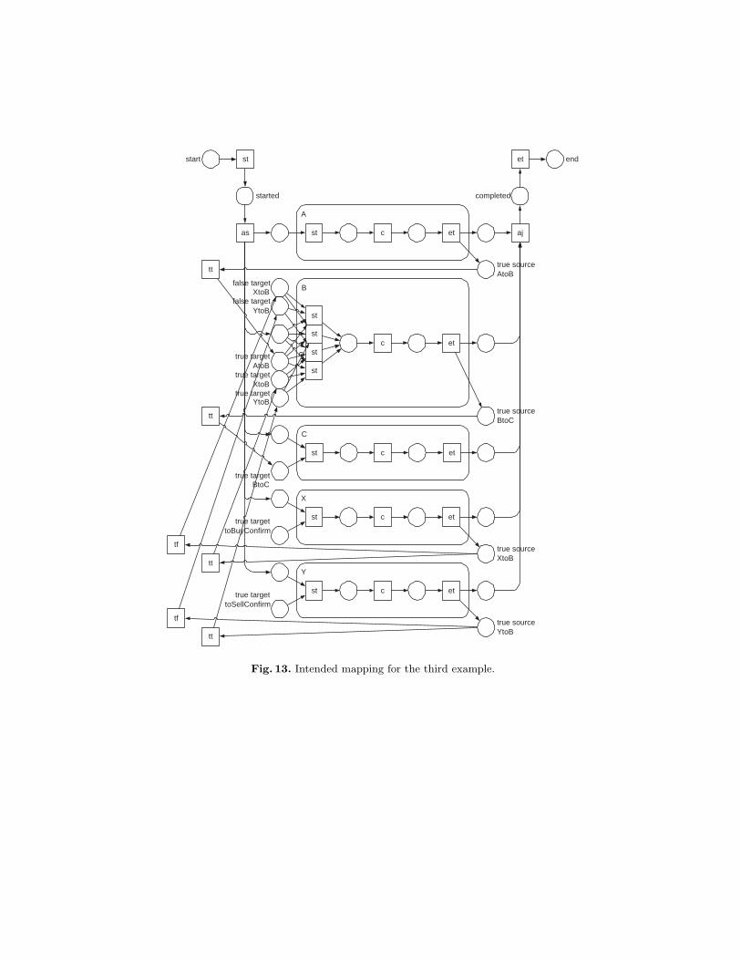
Finally, assume that the preceding flow is slightly rewritten by linking A,B, and C through links (with transition conditions with constant truth-value of“true”) instead of putting them into a sequence. Now, B and thus C will alwaysbe performed. Because the join condition is a disjunction and the transitioncondition of link AtoB is the constant “true”, the join condition will alwaysevaluate to “true”, independent from the values of P(X,B) and P(Y,B).
<flow suppressJoinFailure="no"><links><link name="AtoB"/><link name="BtoC"/><link name="XtoB"/><link name="YtoB"/>
</links><receive name="A"><source linkName="AtoB"/>
</receive><receive name="B"><target linkName="AtoB"/><target linkName="XtoB"/><target linkName="YtoB"/><source linkName="BtoC"/>
</receive><receive name="C"><target linkName="BtoC"/>
</receive><receive name="X"><source linkName="XtoB" transitionCondition="P(X,B)"/>
</receive><receive name="Y"><source linkName="YtoB" transitionCondition="P(Y,B)"/>
</receive></flow>
Mappings Except for the suppressJoinFailure=“no”, we can map the secondexample. Figure 12 shows the intended result. Note that his example is not

as aj
started completed
start endet
etst
etcst
true targetXtoB
etc
st
sf
st
st
true targetYtoB
false targetXtoB
false targetYtoB
etcst
etcst
etcst
tt
tt
tf
tf
true sourceYtoB
true sourceXtoB
A
C
X
Y
B
?
st
Fig. 12. Intended mapping for the second example.
as aj
started completed
start endet
etc
true sourceAtoB
st
A
etc
st
B
true targetAtoB
true targetBtoC
true sourceBtoC
true sourceYtoB
tt
tt
C
etcst
X
true targettoBuyConfirm
etcst
Y
true targettoSellConfirm
tt
tt
etcst
st
st
st
true targetYtoB
true targetXtoB
false targetXtoB
false targetYtoB
true sourceXtoB
tf
tf
st
Fig. 13. Intended mapping for the third example.

(yet) mapped onto a WF-net, as the transition sf in activity B clearly is a sinktransition, which is not covered by any path form start to end. This is due tothe fact that the mapping does not (yet) include scopes and fault handlers. Inthe near future, we hope to add these constructs to the mapping.
Figure 13 shows the intended mapping of the third example. Because in thisexample the join condition cannot fail, we can map it successfully onto a WF-net.
Fig. 14. Oracle BPEL Designer snapshot.
5 Oracle BPEL Process Manager
Using Oracle BPEL Process Manager (and Designer) [16], we have deployed thefollowing, erroneous, BPEL process model.
<sequence name="main"><receive name="receiveInput" partnerLink="client"
portType="tns:Eric1" operation="initiate"variable="input" createInstance="yes"/>
<flow name="flowEric">

<links><link name="linkEric"/>
</links><sequence name="flow-sequence-1"><switch name="switchEric"><case condition="bpws:getVariableData(
"input","payload","/tns:Eric1Request/tns:input")="Eric"">
<empty name="Eric"><source linkName="linkEric"/>
</empty></case><otherwise><empty name="nonEric"><target linkName="linkEric"/>
</empty></otherwise>
</switch></sequence>
</flow><invoke name="callbackClient" partnerLink="client"
portType="tns:Eric1Callback"operation="onResult" inputVariable="output"/>
</sequence>
Figure 14 shows a snapshot of this model using Oracle BPEL Designer. Thisprocess model is clearly erroneous:
– if the condition evaluates to true, the status of the link linkEric is set topositive, but this determined status will never be used;
– if the condition evaluates to false, the process model will deadlock becausethe status of the link linkEric can not be determined;
– the (empty) activity labeled “nonEric” is not viable (it cannot be executed).
However, no warnings or errors were issued during the deployment of this processmodel. This shows that it is not hard to deploy an erroneous BPEL processmodel, which is clearly not without dangers.
Figures 15 and 16 show the audit trails of two instances, one with “Eric”as input and one with “Wil” as input. The first instance is able to complete.However, no warning is issued for the fact that the status of link linkEric isnever used. The second instance is not able to complete (it deadlocks) becausethe status of the link cannot be determined.
We have (manually) mapped the erroneous process onto a WF-net, and haveverified that WF-net using Woflan [19, 20]. Figure 17 shows the diagnostic resultsprovided by Woflan. First of all, Woflan reports (the red X in the bottom rightcorner) that the WF-net is not sound. Furthermore, the conditions (places) thatcorrespond to the link “linkEric” are both improper (unbounded). Obviously,there is something wrong with this link. Even worse, there is no scenario whichavoids improper places (as the number of improper scenarios is 0). Also note

Fig. 15. Audit trail “Eric”.
Fig. 16. Audit trail “Wil”.

Fig. 17. Woflan report on mapped process model.
that Woflan explicitly mentions the task (transition) “flowEric/flow-sequence-1/switchEric/Eric/et” as a possible cause of the improper places (as it is part ofan AND-OR mismatch (TP-handle). Clearly, our approach works and providesthe modeler with valuable information towards correcting possible errors.
6 Related Work
Several attempts have been made to capture the behavior of BPEL in someformal way. Some advocate the use of finite state machines [12, 13], others processalgebras [11], and yet others abstract state machines [9, 10]. Our approach isspecifically tailored towards mapping a BPEL process model onto a WF-net,which enables us to check its soundness. As the aforementioned formalisms donot support the soundness property, we cannot use these mappings. To ourknowledge, some researchers also advocate the use of Petri nets (cf. [15, 17]), butthe corresponding papers have not been published yet.
7 Conclusion
It is not hard to model an erroneous BPEL process model using existing tools.Even worse, it is also straightforward to deploy such models. Current BPEL toolslack the possibility to verify certain basic properties any BPEL process modelshould have. To overcome this weakness, we propose to map BPEL process
models onto models for which strong verification techniques and tools exist:Petri nets (WF-nets, to be precise).
We have shown that large parts of BPEL process models can be mapped ontoWF-net without any problems. Nevertheless, the current mapping is still notcomplete: We still need to add support for scopes, fault handlers, and (possibly)correlations. Nevertheless, the results sofar seem encouraging and consistent withthe behavior of existing BPEL engines.
In the near future, we plan to extend the current mapping to a fully-fledgedmapping. Such a fully-fledged mapping can then be used to verify any BPELprocess model before it is deployed. An ongoing point of attention is the fact thatwe have to be able to map any errors in the resulting WF-net back to the BPELprocess model, but we do not expect any difficulties in this area. As a result, thefully-fledged mapping will be able to guide the modeler of an erroneous BPELprocess model towards correcting the error(s).
References
1. W.M.P. van der Aalst. Verification of workflow nets. In P. Azema and G. Balbo,editors, Application and Theory of Petri Nets 1997, volume 1248 of Lecture Notes inComputer Science, pages 407–426, Toulouse, France, June 1997. Springer, Berlin,Germany.
2. W.M.P. van der Aalst. The application of Petri nets to workflow management.The Journal of Circuits, Systems and Computers, 8(1):21–66, 1998.
3. W.M.P. van der Aalst. Workflow verification: Finding control-flow errors usingPetri-net-based techniques. In W.M.P. van der Aalst, J. Desel, and A. Oberweis,editors, Business Process Management: Models, Techniques, and Empirical Stud-ies, volume 1806 of Lecture Notes in Computer Science, pages 161–183. Springer,Berlin, Germany, 2000.
4. W.M.P. van der Aalst. Don’t go with the flow: Web services composition standardsexposed. IEEE Intelligent Systems, 18:72–76, January/February 2003.
5. BEA, IBM, Microsoft, SAP AG, and Siebel Systems. Busi-ness process execution language for web services (version 1.1).ftp://www6.software.ibm.com/software/developer/library/ws-bpel.pdf (lastvisited in March 2005), 2003.
6. BPML.org. Business process modeling language. www.bpmi.org (last visited inApril 2005), 2002.
7. F. Curbera, M. Duftler, R. Khalaf, W. Nagy, N. Mukhi, and S. Weerawarana.Unraveling the web services web: An introduction to SOAP, WSDL, and UDDI.IEEE Internet Computing, 6(2):86–93, March 2002.
8. F. Curbera, Y. Goland, J. Klein, F. Leymann, D. Roller, S. Thatte, and S. Weer-awarana. Business process execution language for web services, version 1.0. Stan-dards proposal by BEA Systems, International Business Machines Corporation,and Microsoft Corporation, 2002.
9. D. Fahland and W. Reisig. ASM-based semantics for BPEL: The negative controlflow. In D. Beauquier, E. Brger, and A. Slissenko, editors, Proc. 12th InternationalWorkshop on Abstract State Machines, pages 131–151, Paris, France, March 2005.
10. R. Farahbod, U. Glasser, and M. Vajihollahi. Specification and validation of thebusiness process execution language for web services. In W. Zimmermann and

B. Thalheim, editors, Abstract State Machines 2004, volume 3052 of Lecture Notesin Computer Science, pages 79–94, Lutherstadt Wittenberg, Germany, May 2004.Springer, Berlin, Germany.
11. A. Ferrara. Web services: a process algebra approach. In International ConferenceOn Service Oriented Computing: Proceedings of the 2nd international conferenceon Service oriented computing, pages 242–251, New York, NY, USA, 2004. ACMPress.
12. J.A. Fisteus, L.S. Fernandez, and C.D. Kloos. Formal verification of BPEL4WSbusiness collaborations. In K. Bauknecht, M. Bichler, and B. Proll, editors, Pro-ceedings of the 5th International Conference on Electronic Commerce and WebTechnologies (EC-Web ’04), volume 3182 of Lecture Notes in Computer Science,pages 79–94, Zaragoza, Spain, August 2004. Springer, Berlin, Germany.
13. X. Fu, T. Bultan, and J. Su. Analysis of interacting BPEL web services. InInternational World Wide Web Conference: Proceedings of the 13th internationalconference on World Wide Web, pages 621–630, New York, NY, USA, 2004. ACMPress.
14. K.M. van Hee, N. Sidorova, and M. Voorhoeve. Soundness and separability ofworkflow nets in the stepwise refinement approach. In W.M.P. van der Aalst andE. Best, editors, 24th International Conference on Application and Theory of PetriNets (ICATPN 2003), volume 2679 of Lecture Notes in Computer Science, pages337–356, Eindhoven, The Netherlands, June 2003. Springer, Berlin, Germany.
15. A. Martens. Analyzing Web Service Based Business Processes. In M. Cerioli, editor,Proceedings of the 8th International Conference on Fundamental Approaches toSoftware Engineering (FASE 2005), volume 3442 of Lecture Notes in ComputerScience, pages 19–33. Springer, Berlin, Germany, 2005.
16. Oracle. Oracle BPEL process manager. http://www.oracle.com/technology/bpel(last visited in March 2005), 2005.
17. C. Stahl. Transformation von BPEL4WS in Petrinetze (In German). Master’sthesis, Humboldt University, Berlin, Germany, 2004.
18. UN/CEFACT and OASIS. ebXML business process specification schema (version1.01). www.ebxml.org/specs/ebBPSS.pdf (last visited in November 2002), 2001.
19. H.M.W. Verbeek and W.M.P. van der Aalst. Woflan 2.0: A Petri-net-based work-flow diagnosis tool. In M. Nielsen and D. Simpson, editors, Application and Theoryof Petri Nets 2000, volume 1825 of Lecture Notes in Computer Science, pages 475–484. Springer, Berlin, Germany, 2000.
20. H.M.W. Verbeek, T. Basten, and W.M.P. van der Aalst. Diagnozing workflowprocesses using Woflan. The Computer Journal, 44(4):246–279, 2001.
21. W3C. Web service choreography interface (WSCI) 1.0. www.w3.org/TR/wsci (lastvisited in November 2002), 2002.
22. WfMC. Workflow process definition interface - XML process definition language.www.wfmc.org/standards/docs/TC-1025 10 beta xpdl 102502.pdf (last visited inApril 2005), 2002.