analyzing chemical composition of rigid polyurethane (pu) foams using ftir microscopy and drifts-ir
TRANSCRIPT
1 / 15
John Kinyanjui, Ph.D., Jeff Head, Mark Talbott, Ph.DShimadzu Scientific Instruments, Columbia, MD
Analyzing Chemical Composition of Rigid Polyurethane (PU) Foams Using FTIR Microscopy and DRIFTS-IR
2 / 152 / 15
Introduction
The chemical composition of rigid polyurethane foams was studied using FTIR microscopy and diffuse reflectance Fourier transform spectroscopy (DRIFTS) FTIR.
Temperature gradients during the processing of rigid polyurethane (PU) foams leads to chemical gradients that might be observed across the radial and axial dimensions of the foam.
Unreacted reactants and products from side reactions can remain trapped in the cavities of the foam hampering mechanical strength
A highly complex and heterogeneous polymeric composite results.
The chemical composition of the cellular structure of the foam was studied with distinct spectra of the gas filled cell nucleus and cell wall.
FTIR spectroscopy offers an ideal tool for studying variations in chemical composition at both bulk and microscopic levels.
3 / 153 / 15
Experimental Conditions - Reactants
Commercially available rigid polyurethane pour foam starting materials (designated as “part A” and “part B” by manufacturer) were used.
Although the exact formulation was not provided…
• Part A normally contains the diisocyanate.
• Part B normally contains the polyol, water (blowing agent), a catalyst and a surfactant premixed at optimized ratios.
Equal amounts of part A and part B were mixed and stirred until the mixture appeared uniform.
The foam was then allowed to rise and “cure” over a period of five (5) days.
Foam was sectioned and sample measurement carried out on the fifth day.
Based on FTIR results, unique uretoneimine crosslinking functionality might be present in the foam giving clues on exact formulation of starting materials. [1,2]
4 / 154 / 15
Rigid PU Foam Formation Reaction
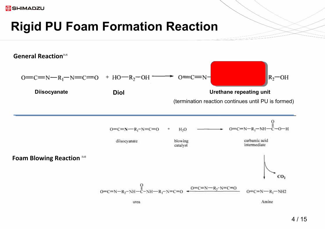
General Reaction[1,2]
Foam Blowing Reaction [1,2]
Diisocyanate Diol Urethane repeating unit
(termination reaction continues until PU is formed)
5 / 155 / 15
Experimental Conditions - Foam Mold Designation
Top
Middle
Bottom
Edge 1
Center
Edge 2
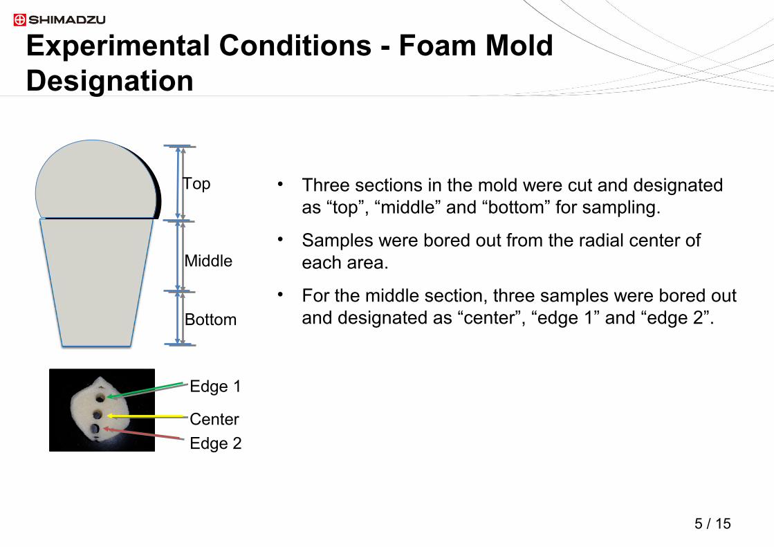
• Three sections in the mold were cut and designated as “top”, “middle” and “bottom” for sampling.
• Samples were bored out from the radial center of each area.
• For the middle section, three samples were bored out and designated as “center”, “edge 1” and “edge 2”.

6 / 156 / 15
Instrumentation
The AIM-8800 connected to IRTracer-100 CO2 filled cell cell wall
Light Microscope Image of PU Foam

7 / 157 / 15
Sample Preparation
Sample bored out from the center of the middle section of the mold was tested. A cylinder microtome was used to produce thin specimens for microscopy.
The PIKE EasiDiff DRIFTS Accessory
Sample Preparation•Pristine samples were bored out and sliced to fit tightly into the 10 mm diameter sample cup provided with the accessory.

8 / 158 / 15
DRIFTS-IR: Top to Bottom of Mold
Composition of the mold changes as you move from top to bottom of the mold.

9 / 159 / 15
DRIFTS IR: Radial Profile of Middle Section of Mold
Edge 1
Center
Edge 2
Edge 2
Center
Edge 1
Composition across the radial axis of the middle section does not change appreciably.
10 / 1510 / 15
FTIR Microscopy: Cell and Cell Wall Spectra
Bulk
Cell
Cell Wall
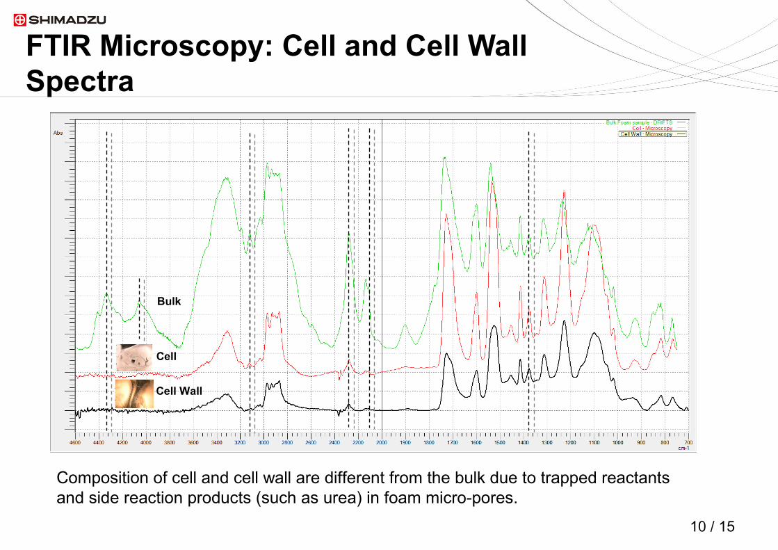
Composition of cell and cell wall are different from the bulk due to trapped reactants and side reaction products (such as urea) in foam micro-pores.
11 / 1511 / 15
Cross-Linking in PU Foam[1,2]
NCO
N C N
N C N
NCO
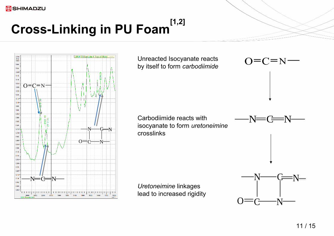
Unreacted Isocyanate reacts by itself to form carbodiimide
Carbodiimide reacts with isocyanate to form uretoneimine crosslinks
Uretoneimine linkages lead to increased rigidity
NCO
N C N
N C N
NCO

12 / 1512 / 15
DRIFTS-IR: Top to Bottom of Mold
Unreacted Isocyanate
Carbodiimide
Uretoneimine linkages
NCON C N
Bottom
Middle
Top
Composition of the mold changes as you move from top to bottom of the mold.
13 / 1513 / 15
Conclusions
• FTIR microscopy was successfully used to show distinct chemical composition at the cellular level as compared to the bulk composition.
• With DRIFTS-IR the spectra of pristine foam samples can be easily collected with minimal sample preparation to provide the bulk chemical properties of the foam.
• Foam aging and curing including the level of cross-linking can also be monitored using DRIFTS-IR.
• • The mechanical properties of the PU foam is highly dependent on the chemical
properties of the foam.[1,2] FTIR data can be used as a tool to assist in tuning the mechanical properties of the foam.
• Previous work has shown that the level of cross-linking in PU foam can be directly correlated to the Young’s modulus of the foam.[1,2]
14 / 1514 / 15
References
1. Mohan, R.B.; O'Toole B.J.; Malpica, J.; Hatchett D.W.; Kodippili G.; and Kinyanjui J.M. Effects of Processing Temperature on ReCrete Polyurethane Foam. Journal of Cellular Plastics 2008; 44: 327-345.
1. Hatchett, D.W.; Kodippili, G; Kinyanjui, J.M.; Benincasa, F.; Sapochak, L. FTIR Analysis of Thermally Processed PU Foam. Polymer Degradation and Stability; 2005; 87(3), 555-561.

15 / 15
Thank you for viewing this presentation. Should you have any questions or require additional information about our research, products or services, please visit our support page: www.ssi.shimadzu.com/support/
@shimadzussiFollow us on Twitter
Need More Info?