analyzing subsurface stress of rolling … · 2017-05-12 · components of a rolling bearing....
TRANSCRIPT

machine design, Vol.4(2012) No.3, ISSN 1821-1259 pp. 139-144
*Correspondence Author’s Address: University of Zilina, Faculty of Mechanical engineering, Univerzitna 1, 010 26 Zilina, Slovak Republic, [email protected]
Preliminary note ANALYZING SUBSURFACE STRESS OF ROLLING BEARINGS FOR LARGE VALUES OF THE EQUIVALENT LOAD BY USING FEM Stefan MEDVECKY1, * - Slavomir HRCEK1 - Rudolf MADAJ1 1 University of Zilina, Faculty of Mechanical Engineering, Zilina, Slovak Republic
Received (08.07.2012); Revised (21.09.2012); Accepted (23.09.2012) Abstract: This paper deals with accurate geometric models of rolling bearing components in the CAD system. This model is then employed to create a static structural analysis used to determine the size of stress between the components of a rolling bearing. Following the stress analysis, we specify the maximum load of a rolling bearing with regards to durability thereof. Key words: roller bearing, maximum load, subsurface stress, von Misses stress, shear stress 1. INTRODUCTION Numerical simulations of rolling bearings are currently predominantly based on the Hertz theory of contact stress of two objects, which is based on pressure calculation in areas of contact of rollers and raceways of bearing rings. This method, however, does not take into account the precise geometry of objects and their influence on stress distribution in rolling bearings. This article details a method permitting the creation of a realistic model of tapered roller bearing which will subsequently be used in a static structural analysis with the aim of determining the influence of operation process parameters under high load using the finite element method. A tapered roller bearing with inner diameter of 460 mm and 39 rolling elements has been selected for the aforementioned analysis. 2. CREATION OF A 3D VIRTUAL MODEL
OF TAPERED ROLLING BEARING Pro/ENGINEER Wildfire, manufactured by PTC Corporation, has been used to create the 3D virtual model of the tapered rolling bearing. The bearing geometry was defined so as to reflect real-life production conditions, including all construction elements, such as concave roller, precise radii of profile curves, etc. This was necessary to assure the correct analysis of contact pressures and evaluate subsurface stress. The distribution and magnitude of contact pressure depends on the geometrical shape of contact rollers. Rolling bearing manufacturers aim to optimize the shape of individual elements so as to assure optimal contact pressure and subsurface stress distribution. However, the manufacturers must also take into account limitations pertaining to the manufacturing process and technological possibilities. The manufacturing drawing defines the basic profile geometry and includes geometrical and shape tolerances reflecting the manufacturing process limitations. Fig. 1 shows a schematic view of the profile of the analyzed bearing with inner ring diameter d460, consisting of three circular arcs.
Fig.1. Profile curve of d460 tapered roller bearing
Static structural analysis of the tapered roller bearing was performed using Ansys/Workbench, allowing the import of geometry from the Pro/ENRINEER system. The interconnection between Pro/ENGINEER and Ansys/Workbench is advantageous (fig. 2), allowing for the modification of model geometry and position by changing relevant parameters. The Workbench environment retains the analysis definition (definition of border conditions, load forces, etc.) and whole post-processing process (evaluation of analysis results).
Fig.2. Section of bearing model d460 constructed in CAD system ProENGINEER and subsequently imported into
CAE system Ansys/Workbench

Stefan Medvecky, Slavomir Hrcek, Rudolf Madaj: Analyzing Subsurface Stress of Rolling Bearings for Large Values of the Equivalent Load by using FEM; Machine Design, Vol.4(2012) No.3, ISSN 1821-1259; pp. 139-144
140
3. DEFINITION OF STATIC ANALYSIS OF TAPERED ROLLER BEARING USING FEM IN ANSYS/WORKBENCH SYSTEM
Choice of appropriate mesh element size is necessary in order to correctly analyze the contact pressure between the roller and roller raceway of outer and inner ring and analysis of subsurface stress. The FEM model mesh for contact pressure analysis should be defined by a minimum of 5 nodes per half width of contact area b1/2. Mesh density along contact profiles has been defined as 3 times the element size along the width of contact area in order to decrease the finite element model computational requirements. [1].
Fig.3. FEM mesh of section of tapered roller
bearing d460 Volume meshing of imported CAD geometry has been performed in Ansys/Workbench using Solid185 element type (fig. 3). Individual bearing elements are in contact because forces acting upon the bearing are transferred between rings (their raceways) and individual rollers. CONTA174 and TARGE170 element types have been employed in Ansys/Workbench to define areas of contact between two rollers. The tapered roller bearing d460 model has been defined in half symmetry of one roller section (360°/39/2) by two planes of symmetry defined via two coordinate systems with axis z perpendicular to the plane of symmetry.
Fig.4. Model of tapered roller bearing d460 with defined
border conditions Multiple contact types – connections between individual rollers have been defined on the finite-element d460 bearing model. Areas between volumes, representing contact volumes of the roller with outer and inner ring, have been defined as Frictional and the coefficient of friction has been set to 0.1. The same contact type has been defined between the face of the roller and inner ring support area. Forces acting on the tapered roller bearing
result in contact between the face of the roller and surface axial force components at inner bearing ring. Border conditions for the static analysis of d460 bearing have been refined as follows (fig. 4.):
removal of one degree of freedom in direction of z axis in cylindrical coordinate system of the front surface of inner ring (axial force retention),
removal of one degree of freedom in direction of z axis in Cartesian coordinate system from the face of the roller due to roller stabilization.
Bearing load condition has been simulated by applying axial force in the z axis direction (cylindrical coordinate system) onto the front area of housing and distributed into multiple load steps. 4. LOAD-BEARING CAPACITY Rolling bearings and their components can be subjected to load stress until reaching a point where external loading forces cause plasticity or permanent deformation. The total loading capacity of rolling bearings depends on the geometry of individual components, the material used, chemical and thermal treatment and distribution of subsurface stress. In order to determine the maximum loading capacity of rolling bearings using FEM analysis, we must employ non-linear material models for individual bearing components. Because raceways of bearing rings and the surface of rollers are hardened, when compared to cores of bearing components, it is necessary to use various material models reflecting the bearing material parameters after chemical and thermal treatment. In our FEM model of tapered roller bearing d460, we used Bilinear Isotropic Hardening material model, defined by Young modulus, Poisson number, yield point and tangent modulus. Table 1 lists values of materials models for bearing steel OVAKO 100Cr6. The material model for hardness 58HRC corresponds to the resulting martensitic steel structure after hardening.
Table 1. Values of materials models Bilinear Isotropic Hardening for bearing FEM model
Material hardness model for steel 58HRC has been used for elements of raceways of bearing rings and surface of roller depth 2.X mm. Cores of bearing components have been modeled using mode 30HRC based on production technology of the tapered roller bearing d460.
Fig.5. Distribution and magnitude of Equivalent Plastic
Strain of tapered roller bearing d460 for various bearing loads

Stefan Medvecky, Slavomir Hrcek, Rudolf Madaj: Analyzing Subsurface Stress of Rolling Bearings for Large Values of the Equivalent Load by using FEM; Machine Design, Vol.4(2012) No.3, ISSN 1821-1259; pp. 139-144
141
Maximum equivalent load force Pe=1.5*Cr has been applied to the tapered roller bearing d460 model with the aim of determining the maximum permissible load force without permanent deformation of the bearing. Equivalent Plastic Strain (EPS) was evaluated post-analysis and we determined that the maximum load force of the tapered roller bearing under given boundary conditions is up to an equivalent load force Pe=1.1*Cr, beyond which plasticity of bearing components occurs (fig. 5). Right hand side of the table lists EPS values (mm/mm) for different loading values of tapered roller bearing d460. The subsequent chapters detail the analysis of surface and subsurface stress of the FEM model of tapered roller bearing d460 depending on the applied load force. Based on evaluation of various stress types, we can predict the projected service life-time of a given rolling bearing under certain boundary conditions and optimize construction thereof in view of extending the service life-time. 5. STATIC ANALYSIS RESULTS – CONTACT
PRESSURE The aim of this analysis was to determine the effect of load on the contact pressure at contact locations between the roller and inner and outer bearing ring. Distribution and magnitude of contact pressure depends on the geometrical shape of contact rollers. The analyzed tapered roller bearing d460 consists of rollers with a profile defined by three circular arcs. The dimensions of profile geometry include manufacturing tolerances since even cutting edge bearing manufacturing technologies are unable to deliver ideally precise geometry. Numerical simulations must be therefore be conceived so as to take into account the said manufacturing tolerances. Analysis of roller profile geometry influence on the distribution of contact pressure within the bearing was necessary due to manufacturing tolerances of the roller profile curve. A total of 4 analyses were performed with various combinations of threshold values of bearing profile tolerances (see table 2). We evaluated the magnitude of contact pressure along the roller profile on the inner ring raceway under constant load Pe=0,6*Cr.
Table 2. Combinations of tolerance threshold values of roller profile
Fig. 6 details the influence of roller profile geometry on the distribution of contact pressure along the roller profile between the said profile and inner ring (wherein contact pressure maxima are located). For comparison purposes, the equivalent load force has been set to a value of Pe=0,6*Cr. The analysis has shown that contact pressure maxima are present in bearings with non-concave rollers and a radius of R = 0,025 mm (analysis no.2). Contact
pressure peaks arise due to curve discontinuities (without tangential bonds) defining the roller profile. In reality, however, the said peaks may be lower because “sharp” curve transitions are not allowed and not manufacturable using even advanced superfinishing operations.
Fig.6. Comparison of contact pressure in different dimensions of profile roller
Further analysis of the contact pressure and subsurface stress will be performed on a model bearing the d460 with roller without concave and the size of radius R = 0.025 mm, which were calculated maximum values of contact pressures. Fig. 7 and 8 show the distribution of contact pressure at raceways of outer and inner ring of bearing d460 due to axial loading.
Fig.7. Distribution of contact pressure at raceway of inner ring(up) and raceway of outer ring (down) –
bearing d460
The analysis result details the influence of load force size on the distribution of contact pressure and is presented graphically. For better representation, the value of contact pressure has been subtracted from nodes of the finite element mesh in locations of maximum contact pressures at raceways of bearing rings, that is from points lying in the plane of symmetry (z=0).

Stefan Medvecky, Slavomir Hrcek, Rudolf Madaj: Analyzing Subsurface Stress of Rolling Bearings for Large Values of the Equivalent Load by using FEM; Machine Design, Vol.4(2012) No.3, ISSN 1821-1259; pp. 139-144
142
Fig.8. Contact pressure along the roller profile at
raceway of outer ring (up) and at raceway of inner ring (down) – bearing d460
of outer ring (left) and at raceway of inner ring (right) – bearing d460 The analysis result details the influence of load force size on the distribution of contact pressure and is presented graphically. For better representation, the value of contact pressure has been subtracted from nodes of the finite element mesh in locations of maximum contact pressures at raceways of bearing rings, that is from points lying in the plane of symmetry (z=0). It is evident from fig. 8 that the maximum contact pressure is present at contact locations between rollers and inner bearing ring. Table 3 lists the maximum values of calculated contact pressures depending on applied load force.
Table 3. Maximum values of contact stress at raceways of bearing rings
When considering an equivalent load force higher than Pe=0.5*Cr , the ISO 281 standard imposes a loading limit in the rating life equation, because the said equation gives satisfactory results for a wide load force, however too high a load could result in undesirable plastic deformation of contact areas between rollers and raceways of rings [2]. In view of the previous, it is necessary to conduct a detailed analysis of subsurface stress of rollers and bearing rings.
6. STATIC ANALYSIS RESULTS – von MISES STRESS
Numerous applications require the use of rolling bearings under load conditions exceeding 0.5 times the basic dynamic load capacity. However, a loading limit exists beyond which the rolling bearing might experience undesirable plastic deformations of raceways of bearing rings or rollers [2]. Criterion of equivalent stress or von Mises stress is used to ascertain whether the yield point (plastic deformation) has been reached due to excess stress. Fig. 9 shows the von Mises stress distribution in areas of contact between the roller and raceways of rings of bearing d460.
Fig.9. Von Mises stress distribution along the profile of tapered roller bearing d460
Fig.10. Dependence of von Mises stress (outer ring up, inner ring down) on equivalent bearing load

Stefan Medvecky, Slavomir Hrcek, Rudolf Madaj: Analyzing Subsurface Stress of Rolling Bearings for Large Values of the Equivalent Load by using FEM; Machine Design, Vol.4(2012) No.3, ISSN 1821-1259; pp. 139-144
143
The magnitude of subsurface von Mises stress is different along the line contact of two different rollers and depends on the magnitude of contact stress between the said rollers in contact (fig. 10). The performed analysis has shown that maximum von Mises stress is located in the plane of symmetry at a depth of 0.446 mm under the surface. Paths were defined along the said depth and von Mises stress was evaluated. Von Mises stress maxima along the roller profile are located at profile curve discontinuities. Additional paths were defined in the symmetry plane, normal to the axis of the roller, to achieve true analysis of the von Mises maxima (fig. 11) due to different depths under the surface (wherein these are present) along the roller profile. The necessary case depth at raceways of bearing rings and rollers is determined based on the mentioned stress analysis and stress is evaluated at the boundary plane of base bearing material and case depth.
Fig.11. Dependence of subsurface von Mises stress (outer ring - roller up, inner ring-roller down) on equivalent
bearing load
Table 4 lists maximum von Mises stress values calculated for tapered roller bearing d460 depending on the applied loading force.
Table 4. Maximum equivalent von Mises stress based on applied bearing load
7. STATIC ANALYSIS RESULTS – SHEAR STRESS τyz
Hertz equations are predominantly used to analyze contact stress, taking into account static pressure loading of contact areas. However, most machine components are moving and their contact areas are sliding or have a tendency to do so. Sliding causes frictional forces which in turn cause shear stress at contact areas, in addition to normal pressure load. This results in a complex stress state around the contact areas. Insufficient analysis of contact stress could lead to erroneous design of machine components, causing component failure due to premature material surface fatigue. This type of damage in most commonly characterized by pitting, crumbling or flaking and disrupts the machine workflow and introduces additional stress, which can result in fractures [1]. Material fatigue in rolling bearings usually manifests itself as pitting, observed at rollers or raceways of bearing rings. Pitting subsequently causes shear stress due to frictional forces between contact areas. Fatigue lifetime of rolling bearings can be determined by analyzing shear stress (based on Wohler curves or S-N material curves). Combined analysis of contact pressure, subsurface von Mises stress and shear stress portrays the complex stress state in contact areas between the rollers and bearing rings.
Fig.12. Distribution of shear stress τyz at contact point outer ring – roller (up) and inner ring - roller (down)
We analyzed and evaluated shear stress in planes of maximum shear stress τyz [1]. The said planes are perpendicular to the cylinder axis for the contact pair
Stefan Medvecky, Slavomir Hrcek, Rudolf Madaj: Analyzing Subsurface Stress of Rolling Bearings for Large Values of the Equivalent Load by using FEM; Machine Design, Vol.4(2012) No.3, ISSN 1821-1259; pp. 139-144
144
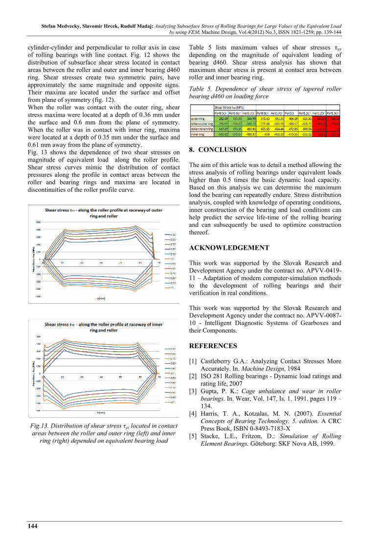
cylinder-cylinder and perpendicular to roller axis in case of rolling bearings with line contact. Fig. 12 shows the distribution of subsurface shear stress located in contact areas between the roller and outer and inner bearing d460 ring. Shear stresses create two symmetric pairs, have approximately the same magnitude and opposite signs. Their maxima are located under the surface and offset from plane of symmetry (fig. 12). When the roller was contact with the outer ring, shear stress maxima were located at a depth of 0.36 mm under the surface and 0.6 mm from the plane of symmetry. When the roller was in contact with inner ring, maxima were located at a depth of 0.35 mm under the surface and 0.61 mm away from the plane of symmetry. Fig. 13 shows the dependence of two shear stresses on magnitude of equivalent load along the roller profile. Shear stress curves mimic the distribution of contact pressures along the profile in contact areas between the roller and bearing rings and maxima are located in discontinuities of the roller profile curve.
Fig.13. Distribution of shear stress τyz located in contact areas between the roller and outer ring (left) and inner
ring (right) depended on equivalent bearing load
Table 5 lists maximum values of shear stresses τyz depending on the magnitude of equivalent loading of bearing d460. Shear stress analysis has shown that maximum shear stress is present at contact area between roller and inner bearing ring.
Table 5. Dependence of shear stress of tapered roller bearing d460 on loading force
8. CONCLUSION The aim of this article was to detail a method allowing the stress analysis of rolling bearings under equivalent loads higher than 0.5 times the basic dynamic load capacity. Based on this analysis we can determine the maximum load the bearing can repeatedly endure. Stress distribution analysis, coupled with knowledge of operating conditions, inner construction of the bearing and load conditions can help predict the service life-time of the rolling bearing and can subsequently be used to optimize construction thereof. ACKNOWLEDGEMENT This work was supported by the Slovak Research and Development Agency under the contract no. APVV-0419-11 – Adaptation of modern computer-simulation methods to the development of rolling bearings and their verification in real conditions. This work was supported by the Slovak Research and Development Agency under the contract no. APVV-0087-10 - Intelligent Diagnostic Systems of Gearboxes and their Components. REFERENCES [1] Castleberry G.A.: Analyzing Contact Stresses More
Accurately. In. Machine Design, 1984 [2] ISO 281 Rolling bearings - Dynamic load ratings and
rating life, 2007 [3] Gupta, P. K.: Cage unbalance and wear in roller
bearings. In. Wear, Vol. 147, Is. 1. 1991. pages 119 – 134.
[4] Harris, T. A., Kotzalas, M. N. (2007). Essential Concepts of Bearing Technology. 5. edition. A CRC Press Book, ISBN 0-8493-7183-X
[5] Stacke, L.E., Fritzon, D.: Simulation of Rolling Element Bearings. Göteborg: SKF Nova AB, 1999.