anchorage regional landfill anchorage, alaska landfill gas collect
TRANSCRIPT

ANCHORAGE REGIONAL LANDFILL
ANCHORAGE, ALASKA
LANDFILL GAS COLLECTION AND CONTROL SYSTEM
DESIGN PLAN
Prepared for
Municipality of Anchorage – Solid Waste Services
September 2004
Prepared by
10300 SW Nimbus Avenue, Suite B
Portland, Oregon 97223-4345 503/603-1023

EMCON
FW\T:\Eng.& Plan\ARL\LFG Collection System\FInal GCCS\GCCS Design Plan - 09-23-04.doc\416-97\ga:1iiRev. 0, 8/24/06
Project 102139 / 02

EMCON enenaperv/T:\Eng.& Plan\ARL\LFG Collection System\FInal GCCS\GCCS Design Plan - 09-23-04.doc\423-96/gaRev. 0, 8/24/06
iii
CONTENTS
1 INTRODUCTION AND CERTIFICATION.........................................................1-1
1.1 Purpose.....................................................................................................................................................1-1
1.2 Certification.............................................................................................................................................1-1
2 EXISTING SITE CONDITIONS...........................................................................2-1
2.1 Landfill Description................................................................................................................................2-1
2.2 Landfill Gas Collection and Control System......................................................................................2-1
3 FUTURE SITE DEVELOPMENT.......................................................................3-1
3.1 Landfill Development Plan.....................................................................................................................3-1
3.2 Landfill Gas Control System Expansion Capabilities.......................................................................3-1
4 COMPLIANCE REVIEW AND EVALUATION.................................................4-1
4.1 Compliance with §60.759(a)(1).............................................................................................................4-1 4.1.1 Control of Surface Emissions............................................................................................................ 4-1 4.1.2 Depths of Refuse................................................................................................................................ 4-1 4.1.3 Landfill Gas Generation Rates and Flow Characteristics .............................................................. 4-2 4.1.4 Landfill Cover Properties ................................................................................................................... 4-2 4.1.5 Landfill Gas Control System Expandability..................................................................................... 4-2 4.1.6 Leachate and Condensate Management......................................................................................... 4-3 4.1.7 Accessibility........................................................................................................................................ 4-3 4.1.8 Compatibility with Refuse Filling Operations................................................................................. 4-3 4.1.9 Integration with Closure End Use.................................................................................................... 4-3 4.1.10 Air Intrusion Control.................................................................................................................... 4-4 4.1.11 Corrosion Resistance.................................................................................................................... 4-4 4.1.12 Fill Settlement................................................................................................................................. 4-4 4.1.13 Resistance to Decomposition Heat ............................................................................................ 4-5
4.2 Compliance with §60.759(a)(2).............................................................................................................4-5
CONTENTS (Continued)
EMCON enenaperv\T:\Eng.& Plan\ARL\LFG Collection System\FInal GCCS\GCCS Design Plan - 09-23-04.doc\416-97\ga:Rev. 0, 8/24/06
iv
4.3 Compliance with §60.759(a)(3).............................................................................................................4-6 4.3.1 Asbestos and Non-degradable materials ........................................................................................ 4-6 4.3.2 Nonproductive Areas ........................................................................................................................ 4-7
4.4 Compliance with §60.759(b)(1), (2), and (3).......................................................................................4-7 4.4.1 Landfill Gas Extraction Component Construction ......................................................................... 4-7 4.4.2 Landfill Gas Extraction Component Installation............................................................................. 4-9 4.4.3 Landfill Gas Extraction Component Connections to LFG Transmission Piping...................... 4-11
4.5 Compliance with §60.759(c)(1) or (2)............................................................................................... 4-11 4.5.1 Existing Landfill Gas Flow Rate Data............................................................................................. 4-12 4.5.2 Future Landfill Gas Flow Rate Estimates....................................................................................... 4-12
4.6 Alternatives and Compliance with §60.752(b)(2)........................................................................... 4-12 4.6.1 Submit a Design Plan ....................................................................................................................... 4-13 4.6.2 Alternatives to the NSPS................................................................................................................. 4-13 4.6.3 Specifications for Active Collection Systems .............................................................................. 4-14 4.6.4 Install a Landfill Gas Collection and Control System.................................................................. 4-14 4.6.5 Control Systems ................................................................................................................................ 4-15
5 LIMITATIONS ........................................................................................................5-1

EMCON enenaperv\T:\Eng.& Plan\ARL\LFG Collection System\FInal GCCS\GCCS Design Plan - 09-23-04.doc\416-97\ga:Rev. 0, 8/24/06
v
APPENDICES
APPENDIX A LANDFILL GAS GENERATION RATE MODELING, RADIUS OF INFLUENCE AND WELL SPACING CALCULATIONS, AND CONDENSATE GENERATION ESTIMATES
APPENDIX B HEAD LOSS ANALYSIS
APPENDIX C GCCS DESIGN PLANS
APPENDIX D SURFACE EMISSIONS MONITORING PLAN

EMCON enenaperv\T:\Eng.& Plan\ARL\LFG Collection System\FInal GCCS\GCCS Design Plan - 09-23-04.doc\423-97\ga:Rev. 0, 8/24/06
1-1
1 INTRODUCTION AND CERTIFICATION
1.1 Purpose
The purpose of this document is to provide a design plan in accordance with the New Source Performance Standards (NSPS) design requirements for the proposed landfill gas collection and control system (GCCS) at the Anchorage Regional Landfill, Anchorage, Alaska, Solid Waste Permit No. 0121-BA001. This plan was prepared pursuant to 40 Code of Federal Regulations (CFR) Part 60, Subpart WWW promulgated March 12, 1996, and Part 62, Subpart GGG Federal Plan Requirements for Municipal Solid Waste Landfills (Federal EG) promulgated November 8, 1999.
1.2 Certification
This NSPS/Federal EG Design Plan report for the GCCS at the Anchorage Regional Landfill has been prepared by EMCON/OWT, Inc. (EMCON) as authorized by the Municipality of Anchorage, Solid Waste Services (SWS).
I certify that the GCCS as described in this plan meets the design requirements specified in 40 CFR §60.759, any alternatives pursuant to 40 CFR §60.752(b)(2), and 40 CFR §62.14356(a)(1). I further certify that this report was prepared by me or under my direct supervision, and that I am a duly registered Professional Engineer.
Douglas M. Gatrell, P.E. Thomas A. Bilgri, P.E. Certifying Engineer Manager – LFG Engineering Services AK PE #10742

EMCON enenaperv\T:\Eng.& Plan\ARL\LFG Collection System\FInal GCCS\GCCS Design Plan - 09-23-04.doc\423-97\ga:Rev. 0, 8/24/06
2-1
2 EXISTING SITE CONDITIONS
2.1 Landfill Description
The Anchorage Regional Landfill (ARL) is located in Anchorage, Alaska. The facility is owned and operated by the Municipality of Anchorage, Solid Waste Services (SWS). The landfill began receiving refuse in November 1987 and has a design capacity of approximately 16 million megagrams (Mg) [approximately 18 million tons] of refuse. The site consists of several contiguous fill areas. These areas are constructed to specifications in excess of Subtitle D and State of Alaska regulations for municipal solid waste disposal facilities. Waste is currently being deposited in cells 1, 2, 3, 4/5, and 6.
2.2 Landfill Gas Collection and Control System
At the time of this report, no GCCS components have been installed or are in operation at this facility. This section identifies components proposed for LFG management at ARL. In conjunction with this report, a phased GCCS design will be implemented in order to comply with the NSPS/Federal EG. The proposed design consists of vertical wells to extract LFG from the disposal area. Extraction wells will have a spacing of approximately 250 to 300 feet.
Horizontal collection trenches may also be utilized in areas that will not reach final grade within 5 years of initial waste deposition. Horizontal collection trenches allow extraction of LFG from areas that are not easily accessible to vertical wells. Horizontal collectors in waste older than 5 years will be utilized to collect LFG once a sufficient barrier of waste (greater than 40 feet) is placed above the collector to reduce the potential for air infiltration.
Permanent lateral and header pipes will be installed below ground surface and constructed of high density polyethylene (HDPE) pipe. Temporary piping may be installed either above or below ground surface. LFG will be conveyed through this piping network to the flare facility, located north of the disposal area. In the future, the LFG may be conveyed off-site or to beneficial-use process equipment.
Condensate that forms in the GCCS piping will gravity drain to condensate pump stations located around the perimeter of the disposal area. Condensate drained by gravity to the

EMCON enenaperv\T:\Eng.& Plan\ARL\LFG Collection System\FInal GCCS\GCCS Design Plan - 09-23-04.doc\423-97\ga:Rev. 0, 8/24/06
2-2
condensate pump stations will be discharged through a force main(s) to leachate collection and storage locations on the site, and ultimately processed with leachate or recirculated back into the waste mass. The condensate that is not recirculated will be disposed of coincidentally with landfill leachate in accordance with the requirements of the facility solid waste permit.
Initially, a 1,500 standard cubic feet per minute (scfm) enclosed landfill gas flare will be installed. This flare is expected to handle landfill gas flow until approximately 2013 based on conservative landfill gas generation modeling. Additional landfill gas control capabilities will be added prior to the capacity of the 1,500 scfm flare is reached.
Additional information and drawings of the GCCS are included in Appendix C.

EMCON enenaperv\T:\Eng.& Plan\ARL\LFG Collection System\FInal GCCS\GCCS Design Plan - 09-23-04.doc\423-97\ga:Rev. 0, 8/24/06
3-1
3 FUTURE SITE DEVELOPMENT
3.1 Landfill Development Plan
The Anchorage Regional Landfill will continue to be filled with waste in accordance with the solid waste permit. Installation of GCCS components is anticipated to be coordinated with fill development and as otherwise required by NSPS regulations regarding installation of GCCS components stipulated in §60.752(b)(2)(ii)(A)(2). Due to operational changes, the GCCS design presented in Appendix C may be altered to maintain compliance with the provisions of the NSPS/Federal EG and to accommodate actual field conditions at the time of construction.
3.2 Landfill Gas Control System Expansion Capabilities
The GCCS will be designed to be readily expanded as fill operations proceed. Vertical wells will typically be installed in areas that have reached final grade. Vertical wells and/or horizontal collection trenches will be installed as an interim control measure in disposal area that have been in place for more than five years, but that are not yet at final refuse grades.
Vertical extraction wells installed prior to reaching final grade will either be extended to the final grade level or abandoned and replaced. This determination will be made based upon the physical condition of the wells, their ability to provide effective LFG extraction, and field conditions at the time of final cap installation.
LFG headers will be sized to accommodate the maximum expected flow, and be fitted with flanged tees for expansion as new collectors are installed, in accordance with NSPS/Federal EG requirements. Additionally, the use of HDPE header piping provides for flexible and efficient connections for future expansion of the header piping system.
Initially, a 1,500 scfm enclosed landfill gas flare will be installed. This flare is expected to handle landfill gas flow until approximately 2013. Prior to reaching this capacity, ARL will plan for additional landfill gas control capabilities. This control could include another flare, multiple flares, engines, turbines, or other state-of-the-art control devices not currently in use.

EMCON enenaperv\T:\Eng.& Plan\ARL\LFG Collection System\FInal GCCS\GCCS Design Plan - 09-23-04.doc\423-97\ga:Rev. 0, 8/24/06
4-1
4 COMPLIANCE REVIEW AND EVALUATION
4.1 Compliance with §60.759(a)(1)
§60.759(a)(1) The collection devices within the interior and along the perimeter areas shall be certified to achieve comprehensive control of surface gas emissions by a professional engineer. The following issues shall be addressed in the design: depths of refuse, refuse gas generation rates and flow characteristics, cover properties, gas system expandability, leachate and condensate management, accessibility, compatibility with filling operations, integration with closure end use, air intrusion control, corrosion resistance, fill settlement, and resistance to the refuse decomposition heat.
The GCCS has been designed to be consistent with NSPS/Federal EG requirements to achieve comprehensive control of both lateral migration and surface emissions of LFG.
Issues related to compliance with §60.759(a)(1) are discussed in the following sections.
Applicable information used in the design of the GCCS is included in Appendix A (Landfill Gas Generation Rate Modeling, Radius of Influence and Well Spacing Calculations, and Condensate Generation Estimates), Appendix B (Head Loss Analysis), Appendix C (GCCS Design Plans), and Appendix D (Surface Emissions Monitoring Plan).
4.1.1 Control of Surface Emissions
The GCCS was designed to minimize both subsurface lateral migration and surface emissions of LFG from the landfill. System performance depends upon the installation of a satisfactory GCCS system, its proper management and installation, and maintenance of a suitable final refuse cover. If there is a temporary exceedance in emissions it will be addressed by appropriate response, evaluating both the GCCS and final cover systems. Appropriate action will then be taken to correct the exceedance as required by NSPS/Federal EG.
4.1.2 Depths of Refuse
Depths of refuse were calculated, at the time of the design of the GCCS, based upon existing topography and permit plan and record documentation of landfill liner grades. The landfill surface elevation was determined from aerial survey data at the time of design.

EMCON enenaperv\T:\Eng.& Plan\ARL\LFG Collection System\FInal GCCS\GCCS Design Plan - 09-23-04.doc\423-97\ga:Rev. 0, 8/24/06
4-2
4.1.3 Landfill Gas Generation Rates and Flow Characteristics
In compliance with §60.752(b)(2)(ii)(A), the maximum expected LFG flow rate for the site was used for sizing the GCCS. A maximum LFG generation rate of 2,400 standard cubic feet per minute (scfm) was calculated using the United States Environmental Protection Agency (USEPA) LandGEM emissions model (k=0.02/year and L0 = 170 m3/Mg), historical waste receipts and the permitted design capacity of the facility. Projected asbestos and contaminated soil receipts were not included since these wastes are no-putrescible and do not contribute to the rate of LFG generation.
The LandGEM emissions model is a design ‘tool’, which uses the information available to project future operating conditions. This model was developed based upon operating conditions at a cross-section of landfills within the United States, and is approved for use by the USEPA. Actual operating parameters may dictate changes in the system flow characteristics and process equipment as the system is developed. These changes will be made in accordance with §60.752.
Landfill gas generation projections are provided in Appendix A.
4.1.4 Landfill Cover Properties
The final cover design will incorporate a composite geosynthetic/armored rock barrier. The primary purpose of the final cover system unit is to preclude precipitation infiltration that would generate additional leachate. However, the final cover system design also provides a significant barrier to LFG emission and air infiltration when combined with an active LFG extraction system. The GCCS will provide components for collecting LFG or relieving pressures from LFG from beneath this layer.
4.1.5 Landfill Gas Control System Expandability
Expandability of the GCCS is achieved by installing tees with blind flanges along the transmission piping. These flanges provide planned access for expansion of the LFG transmission piping in the future. Please note Appendix C, Drawing 2 for typical expansion (i.e. blind flange) locations. In the event that actual LFG flow rates do exceed the capacity of the system, additional GCCS components will be designed and installed in accordance with NSPS requirements.

EMCON enenaperv\T:\Eng.& Plan\ARL\LFG Collection System\FInal GCCS\GCCS Design Plan - 09-23-04.doc\423-97\ga:Rev. 0, 8/24/06
4-3
4.1.6 Leachate and Condensate Management
Leachate management is accomplished through the use of an engineered leachate collection and management system (LCS). Leachate is gravity drained from the LCS to on-site storage lagoons prior to disposal. The LCS is designed according to Subtitle D standards (40 CFR§257 and §258) and is part of the Solid Waste Disposal Permit.
Transmission header and lateral piping will be sloped at a minimum of 3-percent within waste limits (0.5-percent outside waste limits) to promote condensate to flow by gravity to engineered low points in the GCCS piping, for collection of the condensate. Condensate collection pump stations are located at these low points to collect the condensate and pump it to a storage tank. The collected condensate will be discharged to an on-site recirculation system to enhance landfill gas generation. The recirculation system consists of infiltration trenches to allow condensate to percolate back into the waste (Appendix C, Drawing 3). The condensate will be removed from the storage tank via vacuum truck for disposal should inclement weather preclude the use of the recirculation system.
4.1.7 Accessibility
Accessibility to the GCCS components is achieved by installing commonly accessed components (such as wellheads and monitoring ports) on relatively flat surfaces of the landfill or near the landfill’s road network. Wellheads, piping risers, valves and monitoring ports will be installed above grade, or within vaults, to maintain accessibility.
4.1.8 Compatibility with Refuse Filling Operations
Initially, the Phase I landfill gas collection system will be installed in areas that have not reached final grade. The Phase I system has been designed for integration into the final-grade configuration of the GCCS.
As refuse filling operations proceed and portions of the site reach final or near-final grades, additional GCCS components will be installed. This method of installation allows GCCS components to be constructed in accordance with §60.752(b)(2)(ii)(A)(2)(i) and (ii) while minimizing interference of the GCCS with ongoing filling operations.
4.1.9 Integration with Closure End Use
Currently, the post-closure end-use for the site is unspecified and will likely be utilized as open space. Any modifications to the closure end-use must be approved by the Municipality of Anchorage to evaluate their compatibility with the GCCS. Any items of concern related to

EMCON enenaperv\T:\Eng.& Plan\ARL\LFG Collection System\FInal GCCS\GCCS Design Plan - 09-23-04.doc\423-97\ga:Rev. 0, 8/24/06
4-4
maintaining and operating the GCCS will be mitigated by either altering the proposed post-closure end-use or by adjusting or modifying the GCCS in accordance with NSPS/Federal EG requirements.
4.1.10 Air Intrusion Control
Air intrusion is minimized by using soil backfill in the upper zone of the vertical wells and above the horizontal trench collectors. To accommodate the penetration of the geomembrane component of the final cover system, the geomembrane component will be snugly fitted to the pipe penetrations utilizing a “pipe boot”. Potential air intrusion and LFG emissions through the cover system will be controlled through periodic monitoring and adjustment of the GCCS, in coordination with appropriate maintenance of the landfill cover system.
4.1.11 Corrosion Resistance
Corrosion resistance of the GCCS is achieved through the use of corrosion resistant materials or materials that have a corrosion resistant coating, in accordance with 40 CFR§60.759(b)(1). The primary component used in the construction of the GCCS is HDPE piping. All HDPE piping will have a minimum rating of SDR 17. Components will be inspected during routine GCCS monitoring for abrasion, chipping, or other potential deterioration of the components. If damage to the materials is observed that may be detrimental to the performance of the GCCS, the components will be replaced or repaired.
4.1.12 Fill Settlement
Settlement will occur due to decomposition of the refuse. To accommodate refuse settlement, the GCCS components were designed and installed with several features to account for this settlement including:
• LFG extraction well heads connected to the LFG transmission piping via a flexible pipe or hose connection. This allows the LFG piping to accommodate changes in the orientation of the LFG transmission piping or LFG extraction well.
• LFG transmission piping was sloped at sufficient grades (a minimum 3-percent within the waste limits, and 0.5-percent outside the waste limits – see Section 4.1.6) so that reasonable amounts of differential and total settlement may occur without causing pipe breakage, or disrupting the overall flow gradient of the LFG transmission piping.
• HDPE piping will be used for the construction of the header piping and transmission system. HDPE piping is flexible and absorbs differential settlement without breaking or cracking.

EMCON enenaperv\T:\Eng.& Plan\ARL\LFG Collection System\FInal GCCS\GCCS Design Plan - 09-23-04.doc\423-97\ga:Rev. 0, 8/24/06
4-5
4.1.13 Resistance to Decomposition Heat
Resistance of the GCCS to the heat generated as a result of refuse decomposition was achieved through the use of materials tested and proven to withstand temperatures well above those typically found in landfills. The maximum operating temperature for HDPE is in excess of 150°F under low vacuum application conditions such as LFG extraction. The softening temperature, the temperature at which the material begins to exhibit plasticity, is in excess of 250°F – far in excess of normal LFG system operating conditions of 90°F to 120°F. The NSPS/Federal EG requires LFG temperatures at the extraction points to be maintained at less than 131°F or 55°C – 40 CFR §60.753(c).
The GCCS will be inspected during routine LFG system monitoring for heat damage. If heat damage of the GCCS components is observed and is believed to be detrimental to the operation of the GCCS, the cause of the elevated landfill temperature will be investigated, and the GCCS will be adjusted or modified to mitigate the effects of the elevated temperatures.
4.2 Compliance with §60.759(a)(2)
§60.759(a)(2) The sufficient density of gas collection devices determined in paragraph (a)(1) of this section shall address landfill gas migration issues and augmentation of the collection system through the use of active or passive systems at the landfill perimeter or exterior.
Per the definition stated in §60.751, “sufficient density” means “any number, spacing, and combination of collection system components. . . necessary to maintain emission and migration control as determined by measures of performance set forth in this part.” Well spacing at ARL was established using the method described in the book “Methane Generation and Recovery from Landfills, EMCON, 1982.” The values developed by this method were compared to those developed by the equation from the NSPS Background Information Document, 1991 with a more conservative EMCON value utilized for design purposes. This is consistent with spacing criteria used at other landfills and should effectively control surface emissions and subsurface migration of LFG in accordance with NSPS/Federal EG requirements.
Additionally, the spacing of vertical and horizontal extraction wells is within the guidelines defined in Table 5-1, Summary of Suggested Collector Density, Training Course for Landfill Gas NSPS/EG Regulatory Personnel to Review GCCS Design Submittals, North Carolina State University, September, 1998. This guidance recommends a horizontal collector spacing of 30 feet to 50 feet vertically and 150 feet to 300 feet horizontally for horizontal extraction wells, and a vertical well spacing of 250 feet to 300 feet in post-Subtitle D landfills with wet waste.

EMCON enenaperv\T:\Eng.& Plan\ARL\LFG Collection System\FInal GCCS\GCCS Design Plan - 09-23-04.doc\423-97\ga:Rev. 0, 8/24/06
4-6
Since a LFG collection system has not yet been installed, surface emissions monitoring has not yet been required and no surface emissions monitoring data is currently available. Only monitoring data to evaluate the measures of performance for migration control exist. To determine the performance of the GCCS with respect to migration control, quarterly monitoring for off-site migration of combustible gases will be performed at landfill gas probe locations around the perimeter of the facility.
ARL will conduct surface monitoring in accordance with NSPS/Federal EG requirements. If the GCCS at ARL does not meet the measures of performance set forth in the NSPS/Federal EG, the GCCS will be adjusted or modified in accordance with the NSPS/Federal EG requirements. These adjustments or modifications may include the installation of additional collection elements, cap repairs or other actions defined by field conditions at the time of monitoring.
4.3 Compliance with §60.759(a)(3)
§60.759(a)(3) The placement of gas collection devices determined in paragraph (a)(1) of this section shall control all gas producing areas, except as provided by paragraphs (a)(3)(i) and (a)(3)(ii) of this section.
Issues related to compliance with §60.759(a)(3) are discussed in the following sections.
4.3.1 Asbestos and Non-degradable materials
§60.759(a)(3)(i) Any segregated area of asbestos or non-degradable material may be excluded from collection if documented as provided under §60.758(d). The documentation shall provide the nature, date of deposition, location and amount of asbestos or non-degradable material deposited in the area, and shall be provided to the Administrator upon request.
Asbestos has been accepted at this facility. Placement of asbestos and other non-degradable items has not been segregated into one area but instead sporadically spread about the waste disposal area. SWS maintains a map of asbestos disposal locations and the landfill gas wells have been designed to avoid these locations. There is no LFG generation expected from asbestos and non-degradable waste areas of the landfill however due to their spacial distribution these areas have not been excluded from the coverage of the GCCS.
4.3.2 Nonproductive Areas
§60.759(a)(3)(ii) Any nonproductive area of the landfill may be excluded from control, provided that the total of all excluded areas can be shown to contribute less than 1 percent of the total amount of NMOC emissions from the landfill. The amount, location,

EMCON enenaperv\T:\Eng.& Plan\ARL\LFG Collection System\FInal GCCS\GCCS Design Plan - 09-23-04.doc\423-97\ga:Rev. 0, 8/24/06
4-7
and age of the material shall be documented and provided to the Administrator upon request. A separate NMOC emissions estimate shall be made for each section proposed for exclusion, and the sum of all such sections shall be compared to the NMOC emissions estimate for the entire landfill.
A portion of the southwest corner of the landfill has been designated for future placement of construction and demolition debris. This area is not considered productive and LFG extraction is not planned.
4.4 Compliance with §60.759(b)(1), (2), and (3)
§60.759(b) Each owner or operator seeking to comply with §60.752(b)(2)(i)(A) shall construct the gas collection devices using the following equipment or procedures:
4.4.1 Landfill Gas Extraction Component Construction
§60.759(b)(1) The landfill gas extraction components shall be constructed of polyvinyl chloride (PVC), high density polyethylene (HDPE) pipe, fiberglass, stainless steel, or other non-porous corrosion resistant material of suitable dimensions to: convey projected amounts of gases; withstand installation, static, and settlement forces; and withstand planned overburden or traffic loads. The collection system shall extend as necessary to comply with emission and migration standards. Collection devices such as wells and horizontal collectors shall be perforated to allow gas entry without head loss sufficient to impair performance across the intended extent of control. Perforations shall be situated with regard to the need to prevent excessive air infiltration.
Issues related to compliance with §60.759(b)(1) are discussed in the following sections.
The GCCS components will be constructed of polyvinyl chloride (PVC), HDPE, fiberglass, corrosion-resistant steel, Neoprene (gaskets and seals) and other non-porous corrosion resistant materials.
4.4.1.1 Materials

EMCON enenaperv\T:\Eng.& Plan\ARL\LFG Collection System\FInal GCCS\GCCS Design Plan - 09-23-04.doc\423-97\ga:Rev. 0, 8/24/06
4-8
The piping network, blowers and flares will be sized for a maximum estimated flow of 2,400 scfm, as estimated by the USEPA LandGEM emissions model This accounts for the entire MSW disposal capacity, at the final grade development elevations of the landfill. Capacity of the extraction and treatment system components will be phased in as system generation and extraction rates increase.
The Phase I system installation will include installation of extraction components capable of managing 2,400 scfm of LFG extraction. An enclosed flare system as the primary control device will be used at ARL. Please see Section 4.6.5 for a full discussion of the control system.
The GCCS components were designed to withstand the estimated installation, static, settlement, overburden, and traffic loads. Installation loads were determined to be insignificant for GCCS components based on the installation methods used. Static loads from the vacuums applied to the GCCS components and applied loads on the GCCS were both evaluated. Vacuum loads required for the GCCS operation were compared to, and found to be less than, the allowable vacuum loads for the GCCS components. Foundations used for GCCS components were designed to handle the applied loads. The applied loads on GCCS components within the landfill, as well as settlement forces, can not accurately be predicted due to the non-homogeneous nature of the refuse within the landfill.
The GCCS components within the landfill are consistent with those at other landfills which have been in-place for extended periods of time (in excess of 15 years) and verified to be withstanding to the applied static and settlement forces. Overburden and traffic loads for the LFG transmission piping are less than the allowable loads recommended by the piping manufacturer.
The GCCS shall be expanded as necessary to comply with NSPS requirements. Expansion of the GCCS will be certified by a professional engineer and the measures of performance of the LFG system verified as set forth in the NSPS. SWS will conduct monitoring and document compliance of the GCCS in accordance with NSPS requirements. If the GCCS at the ARL does not meet the measures of performance set forth in the NSPS, the GCCS will be adjusted or modified in accordance with NSPS requirements.
4.4.1.2 Component Sizing
4.4.1.3 Component Loading
4.4.1.4 System Expansion

EMCON enenaperv\T:\Eng.& Plan\ARL\LFG Collection System\FInal GCCS\GCCS Design Plan - 09-23-04.doc\423-97\ga:Rev. 0, 8/24/06
4-9
The vertical well and horizontal trench collector elements will be perforated as shown on the design plans (Appendix C) to allow LFG entry without inducing head losses sufficient to impair performance across the intended extent of control. The perforation patterns used for the ARL GCCS design has been successfully used in previous LFG control applications.
The LFG collection elements were designed to prevent excessive air infiltration through the use of solid pipe and solid backfill near the ground surface for vertical LFG extraction wells and for horizontal trenches in the perimeter slope area. Hydrated bentonite plugs and geomembrane seals will be provided around the vertical well casings and horizontal trench access piping where they penetrate the landfill final cover or interim cover systems. Further, air intrusion control will be accomplished through monitoring of the operational monitoring standards for the LFG collection elements in accordance with NSPS/Federal EG requirements. If the GCCS does not meet the operational monitoring standards, it will be adjusted or modified in accordance with NSPS/Federal EG requirements.
4.4.2 Landfill Gas Extraction Component Installation
§60.759(b)(2) Vertical wells shall be placed so as not to endanger underlying liners and shall address the occurrence of water within the landfill. Holes and trenches constructed for piped wells and horizontal collectors shall be of sufficient cross-section so as to allow for their proper construction and completion including, for example, centering of pipes and placement of gravel backfill. Collection devices shall be designed so as not to allow indirect short circuiting of air into the cover or refuse into the collection system or gas into the air. Any gravel used around pipe perforations should be of a dimension so as not to penetrate or block perforations.
Issues related to compliance with §60.759(b)(2) are discussed in the following sections.
Depths of refuse were calculated, at the time of the design of the GCCS, based upon existing topography and permit plan and record documentation of landfill liner grades. The landfill surface elevations were determined from aerial survey data at the time of design. LFG extraction wells will be designed to extend from the landfill surface to within 10 feet of the landfill base, or to seventy five percent of the refuse depth, whichever is the lessor.
4.4.1.5 Component Perforation
4.4.1.6 Air Infiltration
4.4.2.1 Component Placement

EMCON enenaperv\T:\Eng.& Plan\ARL\LFG Collection System\FInal GCCS\GCCS Design Plan - 09-23-04.doc\423-97\ga:Rev. 0, 8/24/06
4-10
The occurrence of leachate within the landfill will be addressed by the leachate and condensate management systems as stated in Section 4.1.6 of this design plan. Leachate management will be accomplished through the leachate collection and management system which includes a leachate drainage layer, perforated collection piping within the landfill cells, and solid piping for gravity discharge to the leachate storage ponds for off-site disposal via truck.
For this reason, it is not expected that free liquids will be encountered during the drilling of wells for the vertical landfill gas extraction wells. If free liquids are encountered, the drilling contractor will attempt to drill through the perched zone of liquids allowing drainage into the underlying waste mass and the leachate collection system. In the event that the zone of perched liquids cannot be penetrated, the well installation may be terminated. If necessary, appropriate measures will be taken to complete the well installation procedure at a nearby location.
If perched liquids are observed within the extraction wells after installation, and it is determined that the liquid level is restrictive to efficient LFG extraction, the leachate level will be reduced. This is typically accomplished by periodic pumping of the liquids using either electric or pneumatic pumping systems. Liquids removed from the well casings will be discharged to the leachate collection system.
Vertical wells constructed for LFG collection elements are of sufficient cross-section to allow for their proper construction and completion, including centering of the pipes and placement of gravel backfill. The wells and trenches will be constructed under supervision of a construction quality assurance program implemented by SWS and verified to be properly constructed.
Record documentation of the well and trench installations will be maintained at SWS offices.
LFG collection elements are designed to prevent air infiltration through the cover, refuse contamination of the collection elements, and direct venting of LFG to the atmosphere. Air intrusion control will be verified through monitoring of gas quality at the extraction components, monitoring of surface emission levels and maintenance of the landfill cover in accordance with NSPS/Federal EG requirements. Separation of the collection elements from the refuse is accomplished by placing gravel backfill in the annular borehole space around extraction well casings and the horizontal trench pipes, providing a filter pack between the refuse and the LFG collection elements. Direct venting of the LFG to the atmosphere is avoided by operating the
4.4.2.2 Leachate
4.4.2.3 Wells and Trenches
4.4.2.4 Component Short Circuiting

EMCON enenaperv\T:\Eng.& Plan\ARL\LFG Collection System\FInal GCCS\GCCS Design Plan - 09-23-04.doc\423-97\ga:Rev. 0, 8/24/06
4-11
GCCS under a controlled application of vacuum and the quarterly monitoring of surface emissions (see Section 4.2).
Gravel of sufficient size is specified to prevent penetration or blockages of the LFG collector pipe perforations. Gravel (non-calcareous) to be utilized will be a nominal 1-inch to 3-inch particle size.
4.4.3 Landfill Gas Extraction Component Connections to LFG Transmission Piping
§60.759(b)(3) Collection devices may be connected to the collection header pipes below or above the landfill surface. The connector assembly shall include a positive closing throttle valve, any necessary seals and couplings, access couplings and at least one sampling port. The collection devices shall be constructed of PVC, HDPE, fiberglass, stainless steel, or other non-porous material of suitable thickness.
The collection devices are connected to the collection header pipes using lateral piping. The lateral piping will be connected to the header piping either above or below the landfill surface, as required by field conditions at the time of installation. The connector assemblies (vertical extraction wellheads) will be located above grade. These assemblies include a positive closing throttle valve, necessary seals and couplings, access ports and couplings, and a minimum of two sampling ports. The collection devices will be constructed of PVC, HDPE, fiberglass, corrosion-resistant steel, and other non-porous materials of suitable thickness. The GCCS components are designed to withstand anticipated installation, static, settlement, overburden, and traffic loads.
4.5 Compliance with §60.759(c)(1) or (2)
§60.759(c) Each owner or operator seeking to comply with §60.752(b)(2)(i)(A) shall convey the landfill gas to a control system in compliance with §60.752(b)(2)(iii) through the collection header pipe(s). The gas mover equipment shall be sized to handle the maximum gas generation flow rate expected over the intended use period of the gas moving equipment using the following procedures:
Issues related to compliance with §60.759(c) are discussed in the following sections.
4.4.2.5 Gravel Backfill

EMCON enenaperv\T:\Eng.& Plan\ARL\LFG Collection System\FInal GCCS\GCCS Design Plan - 09-23-04.doc\423-97\ga:Rev. 0, 8/24/06
4-12
4.5.1 Existing Landfill Gas Flow Rate Data
§60.759(c)(1) For existing collection systems, the flow data shall be used to project the maximum flow rate. If no flow data exists, the procedures in paragraph (c)(2) of this section shall be used.
None of the collection system is currently in place at this facility. As such, no existing flow data is available for comparison. The initial phase of GCCS installation is anticipated to be constructed on or before October 1, 2005.
4.5.2 Future Landfill Gas Flow Rate Estimates
§60.759(c)(2) For new collection systems, the maximum flow rate shall be in accordance with §60.755(a)(1).
A value of 2,400 scfm was determined to be the maximum LFG flow rate at final MSW fill conditions, as estimated by the USEPA LandGEM emissions model. The projected flow rate for the year 2004 is estimated to be approximately 820 scfm. This rate is within the proposed enclosed flare capacity of 2,400 scfm. Landfill gas generation projections are provided in Appendix A.
4.6 Alternatives and Compliance with §60.752(b)(2)
§60.752(b)(2) If the calculated NMOC emission rate is equal to or greater than 50 megagrams per year, the owner or operator shall:
Based on the NSPS/Federal EG method for estimating the potential maximum non-methane organic compound (NMOC) emission rate, the ARL has exceeded the 50 megagrams per year (Mg/yr) threshold and is therefore required to comply with section §60.752(b)(2) of the NSPS/Federal EG. See Appendix F for an estimate of NMOC emission rates. A Tier II NMOC emissions evaluation has been previously prepared under separate cover.

EMCON enenaperv\T:\Eng.& Plan\ARL\LFG Collection System\FInal GCCS\GCCS Design Plan - 09-23-04.doc\423-97\ga:Rev. 0, 8/24/06
4-13
4.6.1 Submit a Design Plan
§60.752(b)(2)(i) Submit a collection and control system design plan prepared by a professional engineer to the Administrator within 1 year:
On behalf of the Municipality of Anchorage – Solid Waste Services, EMCON has prepared this design plan. SWS is submitting this design plan to the Alaska Department of Environmental Quality (ADEQ) with a copy sent to the USEPA Region X office for approval, consistent with NSPS/Federal EG requirements.
4.6.2 Alternatives to the NSPS
§60.752(b)(2)(i)(B) The collection and control system design plan shall include any alternatives to the operational standards, test methods, procedures, compliance measures, monitoring, record keeping or reporting provisions of §60.753 through §60.758 proposed by the owner or operator.
As part of this GCCS plan, SWS requests the flexibility for its LFG collection system operator to place certain LFG wells on an inactive list. In order for LFG wells to be placed on an inactive list they would have to demonstrate the following characteristics:
1. Methane quality that is consistently below 40-percent by volume, and the oxygen quality that is consistently above 5-percent, while less than 1 inch of water column vacuum applied to the well; or
2. Waste placement near the LFG well requires the raising of the casing to a point that it is unsafe for the operator to monitor the NSPS required parameters. In this case, monitoring would resume once waste filling has occurred in the area and it is once again safe to access the LFG well.
SWS believes that LFG wells that exhibit characteristics listed in #1, above, are located in non-decomposable waste or located in waste where the bacteria are not generating adequate amounts of methane to justify extraction. SWS’s request to place these LFG wells on an inactive list will alleviate the compliance requirements for oxygen and vacuum at these LFG wells. SWS will not abandon these inactive LFG wells, but will simply close the wellhead valve and temporarily stop LFG extraction. SWS will continue to perform monthly well monitoring, record keeping, and reporting, as well as the quarterly surface monitoring around these wells, at the inactive LFG wells (similar to all other LFG wells), but we request an exemption from the oxygen, temperature, and pressure requirements of §60.756 during the period which they are classified as inactive.

EMCON enenaperv\T:\Eng.& Plan\ARL\LFG Collection System\FInal GCCS\GCCS Design Plan - 09-23-04.doc\423-97\ga:Rev. 0, 8/24/06
4-14
If during the course of monthly monitoring at these inactive LFG wells, the methane quality should rise and the oxygen concentrations fall (indicating decomposition is returning to the area) or there is an elevated surface methane concentration (i.e. >500 ppm) detected during the quarterly surface monitoring (see details below), SWS will remove the LFG well (or wells) from the inactive list and resume LFG extraction and return the LFG well(s) to compliance with the oxygen, temperature, and pressure requirements of NSPS §60.756.
The operator will continue to conduct quarterly surface emissions monitoring in all areas with designated inactive LFG wells to confirm less than 500 parts per million (ppm) methane emissions (above background) is occurring. Should more than 500 ppm methane emissions (above background) continue after 10 days from the first measured exceedance in areas surrounding inactive LFG wells, SWS will resume vacuum extraction from the inactive wells, or install new LFG wells, or submit an alternate compliance plan to ADEQ and the USEPA for approval.
SWS will include a list of inactive LFG wells in the semi-annual reports, the reason for placing them on an inactive list, and the dates they were deemed inactive.
4.6.3 Specifications for Active Collection Systems
As stated in Sections 4.1 through 4.5 of this design plan, the GCCS proposed at ARL complies with the specifications for active collection systems as stipulated in §60.759 of the NSPS/Federal EG. If future expansions of the GCCS are necessary, they will be designed to comply with the NSPS requirements or any approved alternatives.
4.6.4 Install a Landfill Gas Collection and Control System
§60.752(b)(2)(ii) Install a collection and control system within 18 months of the submittal of the design plan under paragraph (b)(2)(i) of this section that effectively captures the gas generated within the landfill.
§60.752(b)(2)(ii)(A)(2) Collect gas from each area, cell, or group of cells in the landfill in which the initial solid waste has been placed for a period of:
§60.752(b)(2)(ii)(A)(2)(i) 5 years or more if active; or
§60.752(b)(2)(ii)(A)(2)(ii) 2 years or more if closed or at final grade;
The GCCS will be constructed within the prescribed schedule under §60.752(b)(2)(ii). Future expansions to the GCCS will proceed in accordance with the schedules under paragraphs (i) and (ii) of this section.
§60.752(b)(2)(ii)(A)(3) Collect gas at a sufficient extraction rate;
EMCON enenaperv\T:\Eng.& Plan\ARL\LFG Collection System\FInal GCCS\GCCS Design Plan - 09-23-04.doc\423-97\ga:Rev. 0, 8/24/06
4-15
§60.752(b)(2)(ii)(A)(4) Be designed to minimize off-site migration of gas.
In compliance with §60.752(b)(2)(ii)(A)(3) and (4), the GCCS is designed to extract LFG at a sufficient rate so as to minimize the subsurface lateral migration and surface emissions of LFG. This is achieved by sizing and installing sufficient collection elements, transmission piping, blower(s), and flare for the estimated maximum flow rate of LFG.
The GCCS is designed to collect LFG at a sufficient rate, which per the definition in §60.751 means to maintain a negative [gage] pressure (vacuum) at all wellheads without causing air infiltration. Application of a negative gage pressure and minimization of air infiltration will be verified by monitoring the static pressure and nitrogen or oxygen concentrations of the LFG at the extraction points.
Each extraction point will be monitored on a monthly basis in accordance with 40 CFR §60.753 (b) and (c). Monitoring will be performed for pressure, temperature, oxygen and/or nitrogen, at a minimum.
Verification of the GCCS’s ability to minimize off-site subsurface LFG migration is achieved through routine quarterly perimeter monitoring for combustible gases at the site.
SWS will monitor the GCCS extraction points, after installation, for static pressure and for LFG quality in accordance with NSPS/Federal EG requirements and will continue to monitor the perimeter LFG monitoring locations to detect the presence of off-site LFG migration. If off-site LFG migration is detected, SWS will take the necessary actions in accordance with NSPS/Federal EG requirements.
4.6.5 Control Systems
§60.752(b)(2)(iii) Route all the collected gas to a control system that complies with the requirements in either paragraph (b)(2)(iii)(A), (B) or (C) of this section.
The proposed flare system will be installed in phases in order to provide for the most cost effective and flexible options for ARL. Initially, there will be a 1,500 scfm enclosed landfill gas flare installed that is expected to meet landfill gas control requirements of the GCCS until approximately 2013 based on conservative moderately dry/moderately wet landfill gas generation modeling. Prior to the enclosed flare reaching the 1,500 scfm landfill gas flow capacity (based on actual, required flow measurements describe elsewhere in the Plan), ARL will design and install additional control capabilities that will be determined at that time. The control options to be considered could be, but not limited to, additional enclosed flare(s), engines, turbines, or yet to be developed state-of-the-art control devices. In general, ARL will ensure that there will be NSPS/Federal EG compliant control sufficient to control the landfill gas

EMCON enenaperv\T:\Eng.& Plan\ARL\LFG Collection System\FInal GCCS\GCCS Design Plan - 09-23-04.doc\423-97\ga:Rev. 0, 8/24/06
4-16
currently being collected by the GCCS. The required operational performance of these components are stipulated by §60.752(b)(2)(iii)(A) which states:
§60.752(b)(2)(iii)(A) An open flare designed and operated in accordance with §60.18
§60.752(b)(2)(iii)(B) A control system designed and operated to reduce NMOC by 98 weight-percent, or, when an enclosed combustion device is used for control, to either reduce NMOC by 98 weight percent or reduce the outlet NMOC concentration to less than 20 parts per million by volume, dry basis as hexane at 3-percent oxygen. The reduction efficiency or parts per million by volume shall be established by an initial performance test, required under §60.8 using the test methods specified in §60.754(d).
§60.752(b)(2)(iii)(C) Route all collected gas to a treatment system that processes the collected gas for subsequent sale or use. All emissions from any atmospheric vent from the gas treatment system shall be subject to the requirements of paragraph (b)(2)(iii)(A) or (B) of this section.
The enclosed flare at ARL is designed to reduce the concentration of the NMOCs present in the LFG by at least 98 percent by weight or reduce outlet emissions to less than 20 ppmv (dry basis) as hexane, in accordance with §60.752(b)(2)(iii)(B). This reported destruction efficiency is further supported by emissions rate estimates performed by the flare manufacturers on similar units. This information is proprietary and is therefore not included in this design plan. The establishment of the destruction efficiencies using the test methods specified in §60.754(d) will be completed in accordance with NSPS/Federal EG requirements.
In accordance with §60.756, the flare exhaust temperatures and LFG flow rate will be monitored continuously. The flare exhaust will be monitored to insure the presence of a flame using either a thermocouple installed at the flare tip or a UV sensor. The LFG flow rate will be monitored using a thermal mass flow meter, or equivalent monitoring device, installed along the LFG piping, downstream of the blowers.
The LFG flare will be constantly monitored for the presence of a flame, indicating that combustion is occurring. Monitoring for the presence of a flame will be accomplished by an ultraviolet flame scanner, thermo-couple or comparable device. In the event that a flame is not detected, indicating that the combustion process has been disrupted, the monitoring system will automatically:
a) Cut power to the LFG blower(s), and;
b) Initiate the closure of either an electric or pneumatic-activated valve at the inlet to the blower(s). There is no bypass around the control device.
Stopping the blower(s) will cause the LFG extraction process to cease. Closing the inlet valve to the blower(s) will eliminate the potential for direct venting of LFG through the control device

EMCON enenaperv\T:\Eng.& Plan\ARL\LFG Collection System\FInal GCCS\GCCS Design Plan - 09-23-04.doc\423-97\ga:Rev. 0, 8/24/06
4-17
system. This process will be initiated automatically, in the event of flame failure, without the need for operator intervention.

EMCON enenaperv\T:\Eng.& Plan\ARL\LFG Collection System\FInal GCCS\GCCS Design Plan - 09-23-04.doc\423-97\ga:Rev. 0, 8/24/06
5-1
5 LIMITATIONS
This design report has been prepared for the exclusive use of the Municipality of Anchorage – Solid Waste Services for specific application to the projected construction and operation of the GCCS at the Anchorage Regional Landfill. The services described in this report were performed consistent with generally accepted professional consulting principles and practices. No other warranty, expressed or implied, is made. These services were performed consistent with our agreement with our client. Any reliance on this report by a third party is at such party’s sole risk.
Opinions and recommendations contained in this report apply to conditions existing when services were performed and are intended only for the client, purposes, locations, time frames, and project parameters indicated. We are not responsible for the impacts of any changes in environmental standards, practices, or regulations subsequent to performance of services. We do not warrant the accuracy of information supplied by others, nor the use of segregated portions of this report.

APPENDIX A
GAS GENERATION RATE MODELING,
RADIUS OF INFLUENCE CALCULATION, AND CONDENSATE GENERATION ESTIMATES

GAS GENERATION RATE MODELING


RADIUS OF INFLUENCE CALCULATION

Landfill Gas Extraction Well Radii of InfluenceBased on Volume of Affected Refuse
Anchorage Regional Landfill, Anchorage, Alaska
Radius of Influence (ft)(a)(b)(c)
Well Number Well Depth LFG Flow Rate LFG Flow Rate(ft) Condition (scfm) NSPS EMCON
Low 15 200 185A 40 Average 20 231 213
High 25 259 239Low 30 283 261
B 60 Average 40 267 246High 50 299 275Low 45 245 226
C 80 Average 60 283 261High 75 317 292Low 60 253 234
D 100 Average 80 293 270High 100 327 302
MSW Design Tonnage 15,881,446MSW Design Capacity (cyds) 26,469,076Refuse Density 1,200 LFG Generation Rate: 2,500 scfmNSPS Collection Efficiency 85
Average ROI of Shallow Wells (< 45 Feet in Depth) 213 feet Well Spacing = > 369 feetAverage ROI of Medium Depth Wells (45 to 80 Feet in Depth) 254 feet Well Spacing = > 440 feetAverage ROI of Deep Wells (>80 feet in Depth) 270 feet Well Spacing = > 468 feet
Notes:
a) Radius of influence based on the estimated capacity of the facility
b) Anticipated LFG generation rate.
c) Calculations assume 20 feet of solid well casing from ground surface to start of perforations.
ene-naperville\Radius of Influence Spreadsheet.xls ,9/15/2004,11:00 AM EMCON/OWT Solid Waste Services

CONDENSATE GENERATION ESTIMATES

Project Name: Anchorage Regional Landfill GCCS Design & Permitting Date: 9/15/2004Project No.: 102139 / 01000003 By: DMG
CONDENSATE GENERATION ESTIMATE IN BURIED HEADER PIPESLFG COLLECTION SYSTEM
ASSUMPTIONS:1. LFG temp. at the wellhead is the warmest gas.2. LFG traveling in a buried header will try to stabilize its temp. consistant with ground temp.3. Ground temp. below the frost line remains constant year round at 59 degrees F4. LFG header pipe is installed below frost depth.5. The LFG temp. (just before the blower) depends on the distance traveled in buried header pipe and the thermal conductivity of the header pipe.6. Work at the blower compresses the LFG, but no additional condensate is generated due to the heat of compression.
Condensate Generation (gallons/day) = (Ywellhead - Yblower inlet)*LFG Flow*(18/(380*8.35))*60min/hr.*24 hrs./day
Daily Condensate Generation RateLFG Temp. At Blower Inlet (F) FLOW GAS FLOW DATA
59 529 Typical Vacuum at Wellhead -10 in. w.c.60 481 Vacuum at the Blower -40 in. w.c.70 349 Average Wellhead LFG Temp. 90 °F Lookup Table80 172 TOTAL SITE LFG FLOW 2,000 scfm Vapor90 -65 Gas Temp. (F) Pressure
0 0.09035 0.10040 0.12245 0.14750 0.178
P (psia) VP (psia) Y (moles) 55 0.217Wellhead Conditions 14.34 0.699 0.049 60 0.256
65 0.310BLOWER INLET CONDITIONS P (psia) VP (psia) Y (moles) 70 0.363
59 F 13.26 0.217 0.016 75 0.43560 F 13.26 0.256 0.019 80 0.50770 F 13.26 0.363 0.027 85 0.60380 F 13.26 0.507 0.038 90 0.69990 F 13.26 0.699 0.053 95 0.825
100 0.950Y(moles) = VP/P 105 1.115
110 1.280115 1.485120 1.690
C:\RUMPKE\Condensate Estimation Spreadsheet.xls,tab:Buried Header, 9/15/2004, 11:01 AM
Page 1 of 1

APPENDIX B
HEAD LOSS ANALYSIS
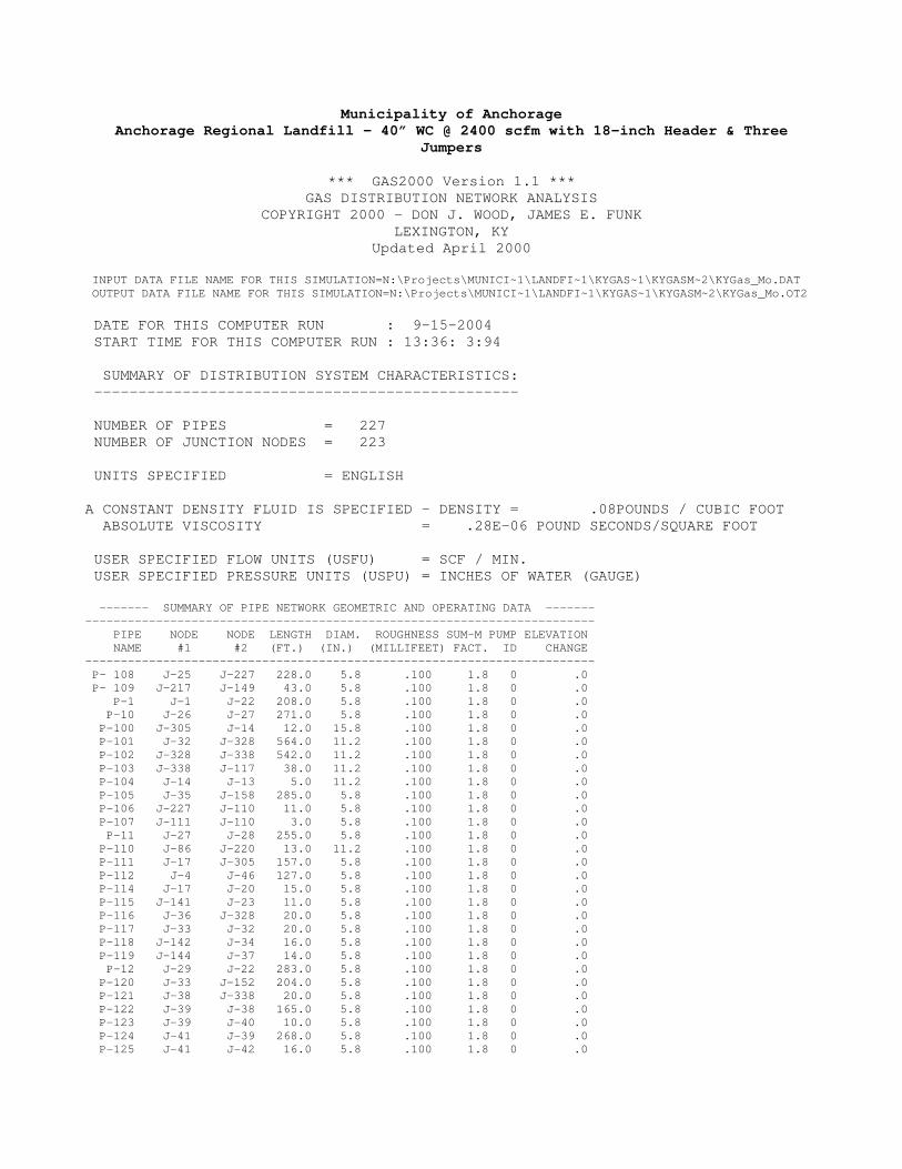
Municipality of Anchorage Anchorage Regional Landfill – 40” WC @ 2400 scfm with 18-inch Header & Three
Jumpers
*** GAS2000 Version 1.1 *** GAS DISTRIBUTION NETWORK ANALYSIS
COPYRIGHT 2000 - DON J. WOOD, JAMES E. FUNK LEXINGTON, KY
Updated April 2000 INPUT DATA FILE NAME FOR THIS SIMULATION=N:\Projects\MUNICI~1\LANDFI~1\KYGAS~1\KYGASM~2\KYGas_Mo.DAT OUTPUT DATA FILE NAME FOR THIS SIMULATION=N:\Projects\MUNICI~1\LANDFI~1\KYGAS~1\KYGASM~2\KYGas_Mo.OT2 DATE FOR THIS COMPUTER RUN : 9-15-2004 START TIME FOR THIS COMPUTER RUN : 13:36: 3:94 SUMMARY OF DISTRIBUTION SYSTEM CHARACTERISTICS: ------------------------------------------------ NUMBER OF PIPES = 227 NUMBER OF JUNCTION NODES = 223 UNITS SPECIFIED = ENGLISH A CONSTANT DENSITY FLUID IS SPECIFIED - DENSITY = .08POUNDS / CUBIC FOOT ABSOLUTE VISCOSITY = .28E-06 POUND SECONDS/SQUARE FOOT USER SPECIFIED FLOW UNITS (USFU) = SCF / MIN. USER SPECIFIED PRESSURE UNITS (USPU) = INCHES OF WATER (GAUGE) ------- SUMMARY OF PIPE NETWORK GEOMETRIC AND OPERATING DATA ------- ------------------------------------------------------------------------ PIPE NODE NODE LENGTH DIAM. ROUGHNESS SUM-M PUMP ELEVATION NAME #1 #2 (FT.) (IN.) (MILLIFEET) FACT. ID CHANGE ------------------------------------------------------------------------ P- 108 J-25 J-227 228.0 5.8 .100 1.8 0 .0 P- 109 J-217 J-149 43.0 5.8 .100 1.8 0 .0 P-1 J-1 J-22 208.0 5.8 .100 1.8 0 .0 P-10 J-26 J-27 271.0 5.8 .100 1.8 0 .0 P-100 J-305 J-14 12.0 15.8 .100 1.8 0 .0 P-101 J-32 J-328 564.0 11.2 .100 1.8 0 .0 P-102 J-328 J-338 542.0 11.2 .100 1.8 0 .0 P-103 J-338 J-117 38.0 11.2 .100 1.8 0 .0 P-104 J-14 J-13 5.0 11.2 .100 1.8 0 .0 P-105 J-35 J-158 285.0 5.8 .100 1.8 0 .0 P-106 J-227 J-110 11.0 5.8 .100 1.8 0 .0 P-107 J-111 J-110 3.0 5.8 .100 1.8 0 .0 P-11 J-27 J-28 255.0 5.8 .100 1.8 0 .0 P-110 J-86 J-220 13.0 11.2 .100 1.8 0 .0 P-111 J-17 J-305 157.0 5.8 .100 1.8 0 .0 P-112 J-4 J-46 127.0 5.8 .100 1.8 0 .0 P-114 J-17 J-20 15.0 5.8 .100 1.8 0 .0 P-115 J-141 J-23 11.0 5.8 .100 1.8 0 .0 P-116 J-36 J-328 20.0 5.8 .100 1.8 0 .0 P-117 J-33 J-32 20.0 5.8 .100 1.8 0 .0 P-118 J-142 J-34 16.0 5.8 .100 1.8 0 .0 P-119 J-144 J-37 14.0 5.8 .100 1.8 0 .0 P-12 J-29 J-22 283.0 5.8 .100 1.8 0 .0 P-120 J-33 J-152 204.0 5.8 .100 1.8 0 .0 P-121 J-38 J-338 20.0 5.8 .100 1.8 0 .0 P-122 J-39 J-38 165.0 5.8 .100 1.8 0 .0 P-123 J-39 J-40 10.0 5.8 .100 1.8 0 .0 P-124 J-41 J-39 268.0 5.8 .100 1.8 0 .0 P-125 J-41 J-42 16.0 5.8 .100 1.8 0 .0

P-126 J-44 J-41 247.0 5.8 .100 1.8 0 .0 P-127 J-44 J-45 13.0 5.8 .100 1.8 0 .0 P-129 J-46 J-49 53.0 5.8 .100 1.8 0 .0 P-13 J-3 J-193 254.0 5.8 .100 1.8 0 .0 P-130 J-137 J-50 10.0 5.8 .100 1.8 0 .0 P-131 J-51 J-217 268.0 5.8 .100 1.8 0 .0 P-132 J-51 J-52 36.0 5.8 .100 1.8 0 .0 P-133 J-55 J-63 249.0 5.8 .100 1.8 0 .0 P-134 J-55 J-60 28.0 5.8 .100 1.8 0 .0 P-135 J-63 J-67 242.0 5.8 .100 1.8 0 .0 P-136 J-63 J-66 30.0 5.8 .100 1.8 0 .0 P-137 J-67 J-166 7.0 5.8 .100 1.8 0 .0 P-138 J-70 J-81 249.0 5.8 .100 1.8 0 .0 P-139 J-70 J-71 31.0 5.8 .100 1.8 0 .0 P-14 J-43 J-189 292.0 5.8 .100 1.8 0 .0 P-140 J-72 J-230 20.0 5.8 .100 1.8 0 .0 P-141 J-73 J-72 180.0 5.8 .100 1.8 0 .0 P-142 J-73 J-74 16.0 5.8 .100 1.8 0 .0 P-143 J-75 J-73 251.0 5.8 .100 1.8 0 .0 P-144 J-75 J-76 12.0 5.8 .100 1.8 0 .0 P-145 J-77 J-75 250.0 5.8 .100 1.8 0 .0 P-146 J-77 J-79 10.0 5.8 .100 1.8 0 .0 P-147 J-80 J-85 249.0 5.8 .100 1.8 0 .0 P-148 J-80 J-82 10.0 5.8 .100 1.8 0 .0 P-149 J-85 J-180 256.0 5.8 .100 1.8 0 .0 P-15 J-16 J-61 288.0 5.8 .100 1.8 0 .0 P-150 J-85 J-90 12.0 5.8 .100 1.8 0 .0 P-151 J-92 J-176 251.0 5.8 .100 1.8 0 .0 P-152 J-92 J-93 14.0 5.8 .100 1.8 0 .0 P-153 J-94 J-92 254.0 5.8 .100 1.8 0 .0 P-154 J-94 J-95 10.0 5.8 .100 1.8 0 .0 P-155 J-96 J-94 246.0 5.8 .100 1.8 0 .0 P-156 J-96 J-97 14.0 5.8 .100 1.8 0 .0 P-157 J-100 J-102 249.0 5.8 .100 1.8 0 .0 P-158 J-100 J-101 21.0 5.8 .100 1.8 0 .0 P-159 J-102 J-104 246.0 5.8 .100 1.8 0 .0 P-16 J-54 J-153 150.0 5.8 .100 1.8 0 .0 P-160 J-102 J-103 19.0 5.8 .100 1.8 0 .0 P-162 J-104 J-105 18.0 5.8 .100 1.8 0 .0 P-163 J-106 J-108 255.0 5.8 .100 1.8 0 .0 P-164 J-106 J-107 19.0 5.8 .100 1.8 0 .0 P-165 J-108 J-68 246.0 5.8 .100 1.8 0 .0 P-166 J-108 J-109 23.0 5.8 .100 1.8 0 .0 P-167 J-65 J-243 20.0 5.8 .100 1.8 0 .0 P-17 J-137 J-46 284.0 5.8 .100 1.8 0 .0 P-18 J-5 J-83 15.0 5.8 .100 1.8 0 .0 P-184 J-132 J-199 240.0 5.8 .100 1.8 0 .0 P-185 J-132 J-133 19.0 5.8 .100 1.8 0 .0 P-186 J-134 J-146 251.0 5.8 .100 1.8 0 .0 P-187 J-134 J-138 20.0 5.8 .100 1.8 0 .0 P-188 J-146 J-148 254.0 5.8 .100 1.8 0 .0 P-189 J-146 J-147 48.0 5.8 .100 1.8 0 .0 P-19 J-132 J-194 251.0 5.8 .100 1.8 0 .0 P-190 J-148 J-54 150.0 5.8 .100 1.8 0 .0 P-191 J-148 J-150 24.0 5.8 .100 1.8 0 .0 P-192 J-153 J-56 253.0 5.8 .100 1.8 0 .0 P-193 J-153 J-154 26.0 5.8 .100 1.8 0 .0 P-194 J-54 J-265 20.0 5.8 .100 1.8 0 .0 P-195 J-78 J-156 250.0 5.8 .100 1.8 0 .0 P-196 J-78 J-155 24.0 5.8 .100 1.8 0 .0 P-197 J-156 J-165 256.0 5.8 .100 1.8 0 .0 P-198 J-156 J-164 20.0 5.8 .100 1.8 0 .0 P-199 J-165 J-168 254.0 5.8 .100 1.8 0 .0 P-2 J-2 J-226 86.0 15.8 .100 1.8 0 .0 P-20 J-106 J-65 180.0 5.8 .100 1.8 0 .0 P-200 J-165 J-167 23.0 5.8 .100 1.8 0 .0 P-201 J-168 J-207 251.0 5.8 .100 1.8 0 .0 P-202 J-168 J-169 20.0 5.8 .100 1.8 0 .0 P-203 J-16 J-18 29.0 5.8 .100 1.8 0 .0 P-204 J-31 J-84 247.0 5.8 .100 1.8 0 .0 P-205 J-31 J-48 20.0 5.8 .100 1.8 0 .0
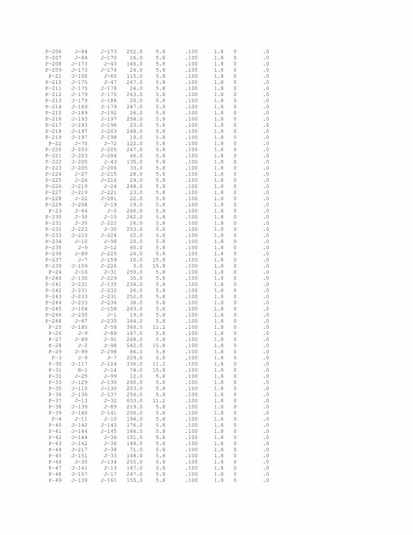
P-206 J-84 J-173 252.0 5.8 .100 1.8 0 .0 P-207 J-84 J-170 26.0 5.8 .100 1.8 0 .0 P-208 J-173 J-43 146.0 5.8 .100 1.8 0 .0 P-209 J-173 J-174 24.0 5.8 .100 1.8 0 .0 P-21 J-100 J-65 115.0 5.8 .100 1.8 0 .0 P-210 J-175 J-47 247.0 5.8 .100 1.8 0 .0 P-211 J-175 J-178 24.0 5.8 .100 1.8 0 .0 P-212 J-179 J-175 263.0 5.8 .100 1.8 0 .0 P-213 J-179 J-186 20.0 5.8 .100 1.8 0 .0 P-214 J-189 J-179 247.0 5.8 .100 1.8 0 .0 P-215 J-189 J-192 26.0 5.8 .100 1.8 0 .0 P-216 J-193 J-197 258.0 5.8 .100 1.8 0 .0 P-217 J-193 J-196 23.0 5.8 .100 1.8 0 .0 P-218 J-197 J-203 248.0 5.8 .100 1.8 0 .0 P-219 J-197 J-198 19.0 5.8 .100 1.8 0 .0 P-22 J-70 J-72 122.0 5.8 .100 1.8 0 .0 P-220 J-203 J-205 247.0 5.8 .100 1.8 0 .0 P-221 J-203 J-204 46.0 5.8 .100 1.8 0 .0 P-222 J-205 J-43 135.0 5.8 .100 1.8 0 .0 P-223 J-205 J-206 33.0 5.8 .100 1.8 0 .0 P-224 J-27 J-215 28.0 5.8 .100 1.8 0 .0 P-225 J-26 J-216 29.0 5.8 .100 1.8 0 .0 P-226 J-219 J-24 248.0 5.8 .100 1.8 0 .0 P-227 J-219 J-221 23.0 5.8 .100 1.8 0 .0 P-228 J-22 J-281 22.0 5.8 .100 1.8 0 .0 P-229 J-208 J-19 19.0 5.8 .100 1.8 0 .0 P-23 J-44 J-5 266.0 5.8 .100 1.8 0 .0 P-230 J-30 J-15 262.0 5.8 .100 1.8 0 .0 P-231 J-30 J-222 26.0 5.8 .100 1.8 0 .0 P-232 J-223 J-30 253.0 5.8 .100 1.8 0 .0 P-233 J-223 J-224 22.0 5.8 .100 1.8 0 .0 P-234 J-10 J-98 20.0 5.8 .100 1.8 0 .0 P-235 J-9 J-12 65.0 5.8 .100 1.8 0 .0 P-236 J-89 J-225 24.0 5.8 .100 1.8 0 .0 P-237 J-7 J-159 10.0 15.8 .100 1.8 0 .0 P-239 J-159 J-226 3.0 15.8 .100 1.8 0 .0 P-24 J-16 J-31 250.0 5.8 .100 1.8 0 .0 P-240 J-130 J-229 35.0 5.8 .100 1.8 0 .0 P-241 J-231 J-135 234.0 5.8 .100 1.8 0 .0 P-242 J-231 J-232 26.0 5.8 .100 1.8 0 .0 P-243 J-233 J-231 252.0 5.8 .100 1.8 0 .0 P-244 J-233 J-234 38.0 5.8 .100 1.8 0 .0 P-245 J-104 J-158 263.0 5.8 .100 1.8 0 .0 P-246 J-235 J-1 19.0 5.8 .100 1.8 0 .0 P-248 J-87 J-235 164.0 5.8 .100 1.8 0 .0 P-25 J-185 J-58 360.0 11.2 .100 1.8 0 .0 P-26 J-9 J-88 167.0 5.8 .100 1.8 0 .0 P-27 J-89 J-91 268.0 5.8 .100 1.8 0 .0 P-28 J-2 J-98 542.0 15.8 .100 1.8 0 .0 P-29 J-99 J-298 86.0 5.8 .100 1.8 0 .0 P-3 J-9 J-7 229.0 5.8 .100 1.8 0 .0 P-30 J-117 J-124 336.0 11.2 .100 1.8 0 .0 P-31 R-1 J-14 74.0 15.8 .100 1.8 0 .0 P-32 J-25 J-99 12.0 5.8 .100 1.8 0 .0 P-33 J-129 J-130 260.0 5.8 .100 1.8 0 .0 P-35 J-110 J-130 253.0 5.8 .100 1.8 0 .0 P-36 J-136 J-137 254.0 5.8 .100 1.8 0 .0 P-37 J-13 J-32 633.0 11.2 .100 1.8 0 .0 P-38 J-139 J-89 219.0 5.8 .100 1.8 0 .0 P-39 J-140 J-141 250.0 5.8 .100 1.8 0 .0 P-4 J-11 J-10 194.0 5.8 .100 1.8 0 .0 P-40 J-142 J-143 176.0 5.8 .100 1.8 0 .0 P-41 J-144 J-145 166.0 5.8 .100 1.8 0 .0 P-42 J-144 J-36 151.0 5.8 .100 1.8 0 .0 P-43 J-142 J-36 148.0 5.8 .100 1.8 0 .0 P-44 J-217 J-38 71.0 5.8 .100 1.8 0 .0 P-45 J-151 J-33 148.0 5.8 .100 1.8 0 .0 P-46 J-35 J-134 255.0 5.8 .100 1.8 0 .0 P-47 J-141 J-13 167.0 5.8 .100 1.8 0 .0 P-48 J-157 J-17 247.0 5.8 .100 1.8 0 .0 P-49 J-139 J-161 155.0 5.8 .100 1.8 0 .0

P-5 J-223 J-10 112.0 5.8 .100 1.8 0 .0 P-50 J-139 J-8 10.0 5.8 .100 1.8 0 .0 P-51 J-137 J-51 285.0 5.8 .100 1.8 0 .0 P-52 J-99 J-131 17.0 5.8 .100 1.8 0 .0 P-53 J-233 J-25 268.0 5.8 .100 1.8 0 .0 P-54 J-162 J-163 85.0 5.8 .100 1.8 0 .0 P-55 J-124 J-55 100.0 5.8 .100 1.8 0 .0 P-56 J-171 J-77 259.0 5.8 .100 1.8 0 .0 P-57 J-172 J-96 103.0 5.8 .100 1.8 0 .0 P-58 J-177 J-80 349.0 5.8 .100 1.8 0 .0 P-59 J-146 J-132 319.0 5.8 .100 1.8 0 .0 P-6 J-279 J-43 22.0 5.8 .100 1.8 0 .0 P-60 J-5 J-61 368.0 5.8 .100 1.8 0 .0 P-61 J-158 J-57 39.0 5.8 .100 1.8 0 .0 P-62 J-53 J-61 24.0 5.8 .100 1.8 0 .0 P-63 J-51 J-64 275.0 5.8 .100 1.8 0 .0 P-64 J-214 J-64 27.0 5.8 .100 1.8 0 .0 P-65 J-200 J-201 100.0 5.8 .100 1.8 0 .0 P-66 J-202 J-78 101.0 5.8 .100 1.8 0 .0 P-67 J-208 J-209 100.0 5.8 .100 1.8 0 .0 P-68 J-210 J-211 100.0 5.8 .100 1.8 0 .0 P-69 J-208 J-212 250.0 5.8 .100 1.8 0 .0 P-7 J-21 J-22 286.0 5.8 .100 1.8 0 .0 P-70 J-213 J-69 20.0 5.8 .100 1.8 0 .0 P-71 J-64 J-69 254.0 5.8 .100 1.8 0 .0 P-72 J-69 J-227 414.0 5.8 .100 1.8 0 .0 P-73 J-218 J-220 116.0 11.2 .100 1.8 0 .0 P-74 J-124 J-163 250.0 11.2 .100 1.8 0 .0 P-75 J-163 J-230 327.0 11.2 .100 1.8 0 .0 P-76 J-230 J-177 397.0 11.2 .100 1.8 0 .0 P-77 J-177 J-172 300.0 11.2 .100 1.8 0 .0 P-78 J-172 J-243 335.0 11.2 .100 1.8 0 .0 P-79 J-243 J-182 443.0 11.2 .100 1.8 0 .0 P-8 J-219 J-235 341.0 5.8 .100 1.8 0 .0 P-80 J-182 J-62 149.0 11.2 .100 1.8 0 .0 P-81 J-62 J-184 100.0 11.2 .100 1.8 0 .0 P-82 J-184 J-59 235.0 11.2 .100 1.8 0 .0 P-83 J-59 J-58 357.0 11.2 .100 1.8 0 .0 P-84 J-35 J-6 12.0 5.8 .100 1.8 0 .0 P-85 J-185 J-188 248.0 11.2 .100 1.8 0 .0 P-86 J-188 J-191 251.0 11.2 .100 1.8 0 .0 P-87 J-191 J-195 254.0 11.2 .100 1.8 0 .0 P-88 J-195 J-265 371.0 11.2 .100 1.8 0 .0 P-89 J-265 J-201 473.0 11.2 .100 1.8 0 .0 P-9 J-26 J-1 196.0 5.8 .100 1.8 0 .0 P-90 J-201 J-202 286.0 11.2 .100 1.8 0 .0 P-91 J-202 J-86 88.0 11.2 .100 1.8 0 .0 P-92 J-279 J-218 89.0 15.8 .100 1.8 0 .0 P-93 J-281 J-279 618.0 15.8 .100 1.8 0 .0 P-94 J-209 J-281 567.0 15.8 .100 1.8 0 .0 P-95 J-211 J-209 248.0 15.8 .100 1.8 0 .0 P-96 J-98 J-211 403.0 15.8 .100 1.8 0 .0 P-97 J-7 J-161 198.0 15.8 .100 1.8 0 .0 P-98 J-161 J-298 226.0 15.8 .100 1.8 0 .0 P-99 J-298 J-305 276.0 15.8 .100 1.8 0 .0 ---------------------------------------------------- JUNCTION NODE DEMAND FPN NAME TITLE (USFU) PRESSURE ---------------------------------------------------- J-1 .00 J-10 .00 J-100 .00 J-101 37 -21.63 J-102 .00 J-103 38 -23.91 J-104 .00 J-105 39 -25.05 J-106 .00 J-107 41 -21.63 J-108 .00
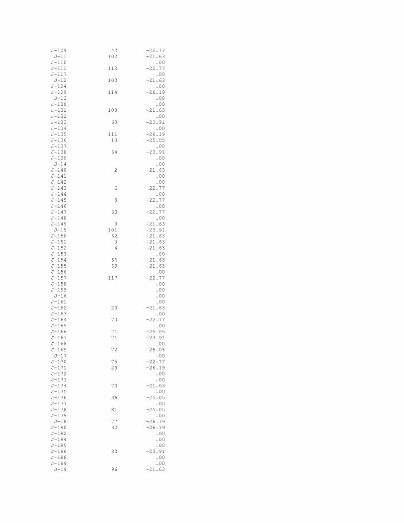
J-109 42 -22.77 J-11 102 -21.63 J-110 .00 J-111 112 -22.77 J-117 .00 J-12 103 -21.63 J-124 .00 J-129 114 -26.19 J-13 .00 J-130 .00 J-131 108 -21.63 J-132 .00 J-133 60 -23.91 J-134 .00 J-135 111 -26.19 J-136 13 -25.05 J-137 .00 J-138 64 -23.91 J-139 .00 J-14 .00 J-140 2 -21.63 J-141 .00 J-142 .00 J-143 6 -22.77 J-144 .00 J-145 8 -22.77 J-146 .00 J-147 63 -22.77 J-148 .00 J-149 9 -21.63 J-15 101 -23.91 J-150 62 -21.63 J-151 3 -21.63 J-152 4 -21.63 J-153 .00 J-154 66 -21.63 J-155 69 -21.63 J-156 .00 J-157 117 -22.77 J-158 .00 J-159 .00 J-16 .00 J-161 .00 J-162 23 -21.63 J-163 .00 J-164 70 -22.77 J-165 .00 J-166 21 -25.05 J-167 71 -23.91 J-168 .00 J-169 72 -25.05 J-17 .00 J-170 75 -22.77 J-171 29 -26.19 J-172 .00 J-173 .00 J-174 74 -21.63 J-175 .00 J-176 36 -25.05 J-177 .00 J-178 81 -25.05 J-179 .00 J-18 77 -26.19 J-180 32 -26.19 J-182 .00 J-184 .00 J-185 .00 J-186 80 -23.91 J-188 .00 J-189 .00 J-19 96 -21.63

J-191 .00 J-192 79 -22.77 J-193 .00 J-194 57 -23.91 J-195 .00 J-196 86 -25.05 J-197 .00 J-198 85 -23.91 J-199 61 -25.05 J-2 .00 J-20 116 -21.63 J-200 68 -21.63 J-201 .00 J-202 .00 J-203 .00 J-204 84 -22.77 J-205 .00 J-206 83 -21.63 J-207 73 -26.19 J-208 .00 J-209 .00 J-21 92 -21.63 J-210 98 -21.63 J-211 .00 J-212 97 -22.77 J-213 115 -25.05 J-214 11 -25.05 J-215 90 -23.91 J-216 89 -22.77 J-217 .00 J-218 CT .00 J-219 .00 J-22 .00 J-220 .00 J-221 94 -23.91 J-222 100 -22.77 J-223 .00 J-224 99 -21.63 J-225 106 -22.77 J-226 .00 J-227 .00 J-229 113 -25.05 J-23 1 -21.63 J-230 .00 J-231 .00 J-232 110 -23.91 J-233 .00 J-234 109 -22.77 J-235 .00 J-24 95 -25.05 J-243 .00 J-25 .00 J-26 .00 J-265 .00 J-27 .00 J-279 .00 J-28 91 -25.05 J-281 .00 J-29 88 -21.63 J-298 .00 J-3 87 -26.19 J-30 .00 J-305 .00 J-31 .00 J-32 .00 J-328 .00 J-33 .00 J-338 .00 J-34 5 -21.63 J-35 .00 J-36 .00

J-37 7 -21.63 J-38 .00 J-39 .00 J-4 18 -26.19 J-40 14 -21.63 J-41 .00 J-42 15 -23.91 J-43 .00 J-44 .00 J-45 16 -25.05 J-46 .00 J-47 82 -26.19 J-48 76 -23.91 J-49 17 -25.05 J-5 .00 J-50 12 -25.05 J-51 .00 J-52 10 -23.91 J-53 78 -26.19 J-54 .00 J-55 .00 J-56 67 -22.77 J-57 40 -26.19 J-58 .00 J-59 .00 J-6 65 -25.05 J-60 19 -21.63 J-61 .00 J-62 .00 J-63 .00 J-64 .00 J-65 .00 J-66 20 -23.91 J-67 .00 J-68 43 -25.05 J-69 .00 J-7 .00 J-70 .00 J-71 24 -21.63 J-72 .00 J-73 .00 J-74 26 -21.63 J-75 .00 J-76 27 -23.91 J-77 .00 J-78 .00 J-79 28 -25.05 J-8 105 -21.63 J-80 .00 J-81 25 -23.91 J-82 30 -23.91 J-83 22 -26.19 J-84 .00 J-85 .00 J-86 .00 J-87 93 -22.77 J-88 104 -22.77 J-89 .00 J-9 .00 J-90 31 -26.19 J-91 107 -23.91 J-92 .00 J-93 35 -25.05 J-94 .00 J-95 34 -23.91 J-96 .00 J-97 33 -21.63 J-98 .00 J-99 .00 R-1 FLARE .00 -40.00

================================================================================ ==================== RESULTS FOR THIS SIMULATION FOLLOW ================= -------------------------------------------------------------------------------- PIPE NODE NODE FLOW LOSS VELOCITY DENSITY FRICTION AREA NO. #1 #2 (USFU) (USPU) (FT/S) (#/CF) FACTOR RATIO -------------------------------------------------------------------------------- P- 108 J-25 J-227 -188.607 .75 16.80 .078 .0203 P- 109 J-217 J-149 -21.632 .00 1.93 .078 .0333 P-1 J-1 J-22 143.454 .42 12.78 .078 .0213 P-10 J-26 J-27 -48.956 .07 4.36 .078 .0270 P-100 J-305 J-14 1579.184 .16 19.05 .078 .0160 P-101 J-32 J-328 -734.289 .90 17.66 .078 .0174 P-102 J-328 J-338 -645.484 .68 15.53 .078 .0178 P-103 J-338 J-117 -450.111 .07 10.83 .078 .0190 P-104 J-14 J-13 -820.816 .17 19.74 .078 .0171 P-105 J-35 J-158 16.344 .01 1.46 .078 .0360 P-106 J-227 J-110 -74.004 .02 6.59 .078 .0245 P-107 J-111 J-110 22.770 .00 2.03 .078 .0328 P-11 J-27 J-28 -25.047 .02 2.23 .078 .0320 P-110 J-86 J-220 474.368 .06 11.41 .078 .0188 P-111 J-17 J-305 44.402 .04 3.95 .078 .0276 P-112 J-4 J-46 26.186 .01 2.33 .078 .0316 P-114 J-17 J-20 -21.632 .00 1.93 .078 .0333 P-115 J-141 J-23 -21.632 .00 1.93 .078 .0333 P-116 J-36 J-328 88.805 .04 7.91 .078 .0235 P-117 J-33 J-32 43.264 .01 3.85 .078 .0278 P-118 J-142 J-34 -21.632 .00 1.93 .078 .0333 P-119 J-144 J-37 -21.632 .00 1.93 .078 .0333 P-12 J-29 J-22 21.632 .02 1.93 .078 .0333 P-120 J-33 J-152 -21.632 .01 1.93 .078 .0333 P-121 J-38 J-338 195.374 .19 17.40 .078 .0201 P-122 J-39 J-38 113.013 .22 10.06 .078 .0224 P-123 J-39 J-40 -21.632 .00 1.93 .078 .0333 P-124 J-41 J-39 91.381 .23 8.14 .078 .0234 P-125 J-41 J-42 -23.909 .00 2.13 .078 .0324 P-126 J-44 J-41 67.473 .12 6.01 .078 .0250 P-127 J-44 J-45 -25.047 .00 2.23 .078 .0320 P-129 J-46 J-49 -25.047 .01 2.23 .078 .0320 P-13 J-3 J-193 26.186 .02 2.33 .078 .0316 P-130 J-137 J-50 -25.047 .00 2.23 .078 .0320 P-131 J-51 J-217 60.728 .11 5.41 .078 .0256 P-132 J-51 J-52 -23.909 .00 2.13 .078 .0324 P-133 J-55 J-63 -48.956 .07 4.36 .078 .0270 P-134 J-55 J-60 -21.632 .00 1.93 .078 .0333 P-135 J-63 J-67 -25.047 .02 2.23 .078 .0320 P-136 J-63 J-66 -23.909 .00 2.13 .078 .0324 P-137 J-67 J-166 -25.047 .00 2.23 .078 .0320 P-138 J-70 J-81 -23.909 .02 2.13 .078 .0324 P-139 J-70 J-71 -21.632 .00 1.93 .078 .0333 P-14 J-43 J-189 -97.913 .28 8.72 .078 .0230 P-140 J-72 J-230 142.315 .10 12.67 .078 .0214 P-141 J-73 J-72 96.774 .18 8.62 .078 .0231 P-142 J-73 J-74 -21.632 .00 1.93 .078 .0333 P-143 J-75 J-73 75.142 .15 6.69 .078 .0244 P-144 J-75 J-76 -23.909 .00 2.13 .078 .0324 P-145 J-77 J-75 51.233 .08 4.56 .078 .0267 P-146 J-77 J-79 -25.047 .00 2.23 .078 .0320 P-147 J-80 J-85 -52.372 .08 4.66 .078 .0265 P-148 J-80 J-82 -23.909 .00 2.13 .078 .0324 P-149 J-85 J-180 -26.186 .02 2.33 .078 .0316 P-15 J-16 J-61 -9.947 .00 .89 .078 .0418 P-150 J-85 J-90 -26.186 .00 2.33 .078 .0316 P-151 J-92 J-176 -25.047 .02 2.23 .078 .0320 P-152 J-92 J-93 -25.047 .00 2.23 .078 .0320 P-153 J-94 J-92 -50.095 .07 4.46 .078 .0268
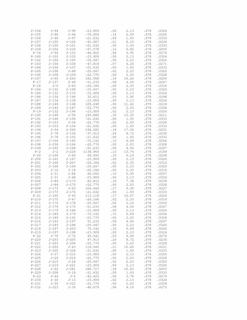
P-154 J-94 J-95 -23.909 .00 2.13 .078 .0324 P-155 J-96 J-94 -74.004 .14 6.59 .078 .0245 P-156 J-96 J-97 -21.632 .00 1.93 .078 .0333 P-157 J-100 J-102 -91.487 .21 8.15 .078 .0234 P-158 J-100 J-101 -21.632 .00 1.93 .078 .0333 P-159 J-102 J-104 -67.578 .12 6.02 .078 .0250 P-16 J-54 J-153 -44.402 .04 3.95 .078 .0276 P-160 J-102 J-103 -23.909 .00 2.13 .078 .0324 P-162 J-104 J-105 -25.047 .00 2.23 .078 .0320 P-163 J-106 J-108 -47.818 .07 4.26 .078 .0271 P-164 J-106 J-107 -21.632 .00 1.93 .078 .0333 P-165 J-108 J-68 -25.047 .02 2.23 .078 .0320 P-166 J-108 J-109 -22.770 .00 2.03 .078 .0328 P-167 J-65 J-243 182.568 .16 16.26 .078 .0204 P-17 J-137 J-46 -51.233 .08 4.56 .078 .0267 P-18 J-5 J-83 -26.186 .00 2.33 .078 .0316 P-184 J-132 J-199 -25.047 .02 2.23 .078 .0320 P-185 J-132 J-133 -23.909 .00 2.13 .078 .0324 P-186 J-134 J-146 32.612 .03 2.90 .078 .0298 P-187 J-134 J-138 -23.909 .00 2.13 .078 .0324 P-188 J-146 J-148 128.248 .40 11.42 .078 .0218 P-189 J-146 J-147 -22.770 .00 2.03 .078 .0328 P-19 J-132 J-194 -23.909 .02 2.13 .078 .0324 P-190 J-148 J-54 149.880 .35 13.35 .078 .0211 P-191 J-148 J-150 -21.632 .00 1.93 .078 .0333 P-192 J-153 J-56 -22.770 .02 2.03 .078 .0328 P-193 J-153 J-154 -21.632 .00 1.93 .078 .0333 P-194 J-54 J-265 194.282 .18 17.30 .078 .0201 P-195 J-78 J-156 -97.913 .24 8.72 .078 .0230 P-196 J-78 J-155 -21.632 .00 1.93 .078 .0333 P-197 J-156 J-165 -75.142 .15 6.69 .078 .0244 P-198 J-156 J-164 -22.770 .00 2.03 .078 .0328 P-199 J-165 J-168 -51.233 .08 4.56 .078 .0267 P-2 J-2 J-226 1138.964 .13 13.74 .078 .0169 P-20 J-106 J-65 69.450 .10 6.19 .078 .0248 P-200 J-165 J-167 -23.909 .00 2.13 .078 .0324 P-201 J-168 J-207 -26.186 .02 2.33 .078 .0316 P-202 J-168 J-169 -25.047 .00 2.23 .078 .0320 P-203 J-16 J-18 -26.186 .00 2.33 .078 .0316 P-204 J-31 J-84 60.042 .10 5.35 .078 .0257 P-205 J-31 J-48 -23.909 .00 2.13 .078 .0324 P-206 J-84 J-173 82.812 .18 7.38 .078 .0239 P-207 J-84 J-170 -22.770 .00 2.03 .078 .0328 P-208 J-173 J-43 104.444 .17 9.30 .078 .0227 P-209 J-173 J-174 -21.632 .00 1.93 .078 .0333 P-21 J-100 J-65 113.118 .17 10.07 .078 .0224 P-210 J-175 J-47 -26.186 .02 2.33 .078 .0316 P-211 J-175 J-178 -25.047 .00 2.23 .078 .0320 P-212 J-179 J-175 -51.233 .08 4.56 .078 .0267 P-213 J-179 J-186 -23.909 .00 2.13 .078 .0324 P-214 J-189 J-179 -75.142 .15 6.69 .078 .0244 P-215 J-189 J-192 -22.770 .00 2.03 .078 .0328 P-216 J-193 J-197 51.233 .08 4.56 .078 .0267 P-217 J-193 J-196 -25.047 .00 2.23 .078 .0320 P-218 J-197 J-203 75.142 .15 6.69 .078 .0244 P-219 J-197 J-198 -23.909 .00 2.13 .078 .0324 P-22 J-70 J-72 45.541 .03 4.06 .078 .0274 P-220 J-203 J-205 97.913 .24 8.72 .078 .0230 P-221 J-203 J-204 -22.770 .00 2.03 .078 .0328 P-222 J-205 J-43 119.545 .21 10.65 .078 .0221 P-223 J-205 J-206 -21.632 .00 1.93 .078 .0333 P-224 J-27 J-215 -23.909 .00 2.13 .078 .0324 P-225 J-26 J-216 -22.770 .00 2.03 .078 .0328 P-226 J-219 J-24 -25.047 .02 2.23 .078 .0320 P-227 J-219 J-221 -23.909 .00 2.13 .078 .0324 P-228 J-22 J-281 186.717 .18 16.63 .078 .0203 P-229 J-208 J-19 -21.632 .00 1.93 .078 .0333 P-23 J-44 J-5 -42.425 .06 3.78 .078 .0279 P-230 J-30 J-15 -23.909 .02 2.13 .078 .0324 P-231 J-30 J-222 -22.770 .00 2.03 .078 .0328 P-232 J-223 J-30 -46.679 .06 4.16 .078 .0273

P-233 J-223 J-224 -21.632 .00 1.93 .078 .0333 P-234 J-10 J-98 89.943 .04 8.01 .078 .0235 P-235 J-9 J-12 -21.632 .01 1.93 .078 .0333 P-236 J-89 J-225 -22.770 .00 2.03 .078 .0328 P-237 J-7 J-159 -1138.964 .08 13.74 .078 .0169 P-239 J-159 J-226 -1138.964 .08 13.74 .078 .0169 P-24 J-16 J-31 36.133 .04 3.22 .078 .0290 P-240 J-130 J-229 -25.047 .00 2.23 .078 .0320 P-241 J-231 J-135 -26.186 .02 2.33 .078 .0316 P-242 J-231 J-232 -23.909 .00 2.13 .078 .0324 P-243 J-233 J-231 -50.095 .07 4.46 .078 .0268 P-244 J-233 J-234 -22.770 .00 2.03 .078 .0328 P-245 J-104 J-158 -42.530 .06 3.79 .078 .0279 P-246 J-235 J-1 71.727 .03 6.39 .078 .0247 P-248 J-87 J-235 22.770 .01 2.03 .078 .0328 P-25 J-185 J-58 -138.909 .03 3.34 .078 .0243 P-26 J-9 J-88 -22.770 .01 2.03 .078 .0328 P-27 J-89 J-91 -23.909 .02 2.13 .078 .0324 P-28 J-2 J-98 -1138.964 .39 13.74 .078 .0169 P-29 J-99 J-298 283.105 .76 25.21 .078 .0189 P-3 J-9 J-7 44.402 .05 3.95 .078 .0276 P-30 J-117 J-124 -450.111 .24 10.83 .078 .0190 P-31 R-1 J-14 -2400.000 .52 28.95 .078 .0150 P-32 J-25 J-99 261.473 .29 23.29 .078 .0191 P-33 J-129 J-130 26.186 .02 2.33 .078 .0316 P-35 J-110 J-130 -51.233 .08 4.56 .078 .0267 P-36 J-136 J-137 25.047 .02 2.23 .078 .0320 P-37 J-13 J-32 -777.552 1.10 18.70 .078 .0172 P-38 J-139 J-89 -46.679 .06 4.16 .078 .0273 P-39 J-140 J-141 21.632 .02 1.93 .078 .0333 P-4 J-11 J-10 21.632 .01 1.93 .078 .0333 P-40 J-142 J-143 -22.770 .01 2.03 .078 .0328 P-41 J-144 J-145 -22.770 .01 2.03 .078 .0328 P-42 J-144 J-36 44.402 .04 3.95 .078 .0276 P-43 J-142 J-36 44.402 .04 3.95 .078 .0276 P-44 J-217 J-38 82.360 .07 7.33 .078 .0239 P-45 J-151 J-33 21.632 .01 1.93 .078 .0333 P-46 J-35 J-134 8.703 .00 .78 .078 .0437 P-47 J-141 J-13 43.264 .04 3.85 .078 .0278 P-48 J-157 J-17 22.770 .02 2.03 .078 .0328 P-49 J-139 J-161 68.311 .08 6.08 .078 .0249 P-5 J-223 J-10 68.311 .07 6.08 .078 .0249 P-50 J-139 J-8 -21.632 .00 1.93 .078 .0333 P-51 J-137 J-51 101.328 .29 9.02 .078 .0229 P-52 J-99 J-131 -21.632 .00 1.93 .078 .0333 P-53 J-233 J-25 72.865 .15 6.49 .078 .0246 P-54 J-162 J-163 21.632 .01 1.93 .078 .0333 P-55 J-124 J-55 -70.588 .06 6.29 .078 .0247 P-56 J-171 J-77 26.186 .02 2.33 .078 .0316 P-57 J-172 J-96 -95.636 .11 8.52 .078 .0232 P-58 J-177 J-80 -76.281 .21 6.79 .078 .0243 P-59 J-146 J-132 -72.865 .18 6.49 .078 .0246 P-6 J-279 J-43 -321.901 .51 28.67 .078 .0185 P-60 J-5 J-61 -16.239 .01 1.45 .078 .0361 P-61 J-158 J-57 -26.186 .01 2.33 .078 .0316 P-62 J-53 J-61 26.186 .00 2.33 .078 .0316 P-63 J-51 J-64 64.509 .12 5.75 .078 .0253 P-64 J-214 J-64 25.047 .00 2.23 .078 .0320 P-65 J-200 J-201 21.632 .01 1.93 .078 .0333 P-66 J-202 J-78 -119.545 .17 10.65 .078 .0221 P-67 J-208 J-209 44.402 .03 3.95 .078 .0276 P-68 J-210 J-211 21.632 .01 1.93 .078 .0333 P-69 J-208 J-212 -22.770 .02 2.03 .078 .0328 P-7 J-21 J-22 21.632 .02 1.93 .078 .0333 P-70 J-213 J-69 25.047 .00 2.23 .078 .0320 P-71 J-64 J-69 89.556 .21 7.98 .078 .0235 P-72 J-69 J-227 114.604 .51 10.21 .078 .0223 P-73 J-218 J-220 -474.368 .13 11.41 .078 .0188 P-74 J-124 J-163 -379.522 .14 9.13 .078 .0196 P-75 J-163 J-230 -357.890 .15 8.61 .078 .0199 P-76 J-230 J-177 -215.575 .07 5.19 .078 .0221

P-77 J-177 J-172 -139.295 .03 3.35 .078 .0243 P-78 J-172 J-243 -43.659 .00 1.05 .078 .0327 P-79 J-243 J-182 138.909 .03 3.34 .078 .0243 P-8 J-219 J-235 48.956 .09 4.36 .078 .0270 P-80 J-182 J-62 138.909 .01 3.34 .078 .0243 P-81 J-62 J-184 138.909 .01 3.34 .078 .0243 P-82 J-184 J-59 138.909 .02 3.34 .078 .0243 P-83 J-59 J-58 138.909 .03 3.34 .078 .0243 P-84 J-35 J-6 -25.047 .00 2.23 .078 .0320 P-85 J-185 J-188 138.909 .02 3.34 .078 .0243 P-86 J-188 J-191 138.909 .02 3.34 .078 .0243 P-87 J-191 J-195 138.909 .02 3.34 .078 .0243 P-88 J-195 J-265 138.909 .03 3.34 .078 .0243 P-89 J-265 J-201 333.191 .18 8.01 .078 .0201 P-9 J-26 J-1 71.727 .11 6.39 .078 .0247 P-90 J-201 J-202 354.823 .13 8.54 .078 .0199 P-91 J-202 J-86 474.368 .11 11.41 .078 .0188 P-92 J-279 J-218 -474.368 .02 5.72 .078 .0200 P-93 J-281 J-279 -796.269 .22 9.60 .078 .0180 P-94 J-209 J-281 -982.986 .30 11.86 .078 .0174 P-95 J-211 J-209 -1027.389 .18 12.39 .078 .0172 P-96 J-98 J-211 -1049.021 .26 12.65 .078 .0172 P-97 J-7 J-161 1183.366 .21 14.27 .078 .0168 P-98 J-161 J-298 1251.677 .25 15.10 .078 .0166 P-99 J-298 J-305 1534.781 .41 18.51 .078 .0161 R-1 R-1 R-1 -2400.000 .00 .01 .078 .0375 -------------------------------------------------------------------------------- JUNCTION NODE DEMAND PRESSURE PRESSURE PRESSURE DENSITY NAME TITLE (USFU) (USPU) (PSIA) (PSIG) #/CF -------------------------------------------------------------------------------- J-1 .00 -36.43 13.38 -1.31 .078 J-10 .00 -37.73 13.33 -1.36 .078 J-100 .00 -35.60 13.41 -1.28 .078 J-101 37 -21.63 -35.60 13.41 -1.28 .078 J-102 .00 -35.38 13.42 -1.28 .078 J-103 38 -23.91 -35.38 13.42 -1.28 .078 J-104 .00 -35.26 13.42 -1.27 .078 J-105 39 -25.05 -35.26 13.42 -1.27 .078 J-106 .00 -35.67 13.41 -1.29 .078 J-107 41 -21.63 -35.67 13.41 -1.29 .078 J-108 .00 -35.60 13.41 -1.28 .078 J-109 42 -22.77 -35.60 13.41 -1.28 .078 J-11 102 -21.63 -37.72 13.34 -1.36 .078 J-110 .00 -37.08 13.36 -1.34 .078 J-111 112 -22.77 -37.08 13.36 -1.34 .078 J-117 .00 -36.56 13.38 -1.32 .078 J-12 103 -21.63 -38.39 13.31 -1.39 .078 J-124 .00 -36.32 13.39 -1.31 .078 J-129 114 -26.19 -36.98 13.36 -1.33 .078 J-13 .00 -39.31 13.28 -1.42 .078 J-130 .00 -37.01 13.36 -1.34 .078 J-131 108 -21.63 -38.14 13.32 -1.38 .078 J-132 .00 -35.05 13.43 -1.26 .078 J-133 60 -23.91 -35.05 13.43 -1.26 .078 J-134 .00 -35.20 13.43 -1.27 .078 J-135 111 -26.19 -37.61 13.34 -1.36 .078 J-136 13 -25.05 -35.95 13.40 -1.30 .078 J-137 .00 -35.97 13.40 -1.30 .078 J-138 64 -23.91 -35.19 13.43 -1.27 .078 J-139 .00 -38.57 13.30 -1.39 .078 J-14 .00 -39.48 13.27 -1.42 .078 J-140 2 -21.63 -39.26 13.28 -1.42 .078 J-141 .00 -39.27 13.28 -1.42 .078 J-142 .00 -37.23 13.35 -1.34 .078 J-143 6 -22.77 -37.22 13.35 -1.34 .078 J-144 .00 -37.23 13.35 -1.34 .078 J-145 8 -22.77 -37.22 13.35 -1.34 .078 J-146 .00 -35.23 13.42 -1.27 .078

J-147 63 -22.77 -35.23 13.43 -1.27 .078 J-148 .00 -35.63 13.41 -1.29 .078 J-149 9 -21.63 -36.37 13.38 -1.31 .078 J-15 101 -23.91 -37.58 13.34 -1.36 .078 J-150 62 -21.63 -35.63 13.41 -1.29 .078 J-151 3 -21.63 -38.19 13.32 -1.38 .078 J-152 4 -21.63 -38.18 13.32 -1.38 .078 J-153 .00 -35.94 13.40 -1.30 .078 J-154 66 -21.63 -35.94 13.40 -1.30 .078 J-155 69 -21.63 -36.31 13.39 -1.31 .078 J-156 .00 -36.07 13.39 -1.30 .078 J-157 117 -22.77 -39.26 13.28 -1.42 .078 J-158 .00 -35.21 13.43 -1.27 .078 J-159 .00 -38.37 13.31 -1.38 .078 J-16 .00 -35.80 13.40 -1.29 .078 J-161 .00 -38.66 13.30 -1.39 .078 J-162 23 -21.63 -36.17 13.39 -1.31 .078 J-163 .00 -36.18 13.39 -1.31 .078 J-164 70 -22.77 -36.06 13.39 -1.30 .078 J-165 .00 -35.91 13.40 -1.30 .078 J-166 21 -25.05 -36.16 13.39 -1.30 .078 J-167 71 -23.91 -35.91 13.40 -1.30 .078 J-168 .00 -35.84 13.40 -1.29 .078 J-169 72 -25.05 -35.83 13.40 -1.29 .078 J-17 .00 -39.28 13.28 -1.42 .078 J-170 75 -22.77 -35.94 13.40 -1.30 .078 J-171 29 -26.19 -35.50 13.42 -1.28 .078 J-172 .00 -35.93 13.40 -1.30 .078 J-173 .00 -36.12 13.39 -1.30 .078 J-174 74 -21.63 -36.12 13.39 -1.30 .078 J-175 .00 -35.79 13.40 -1.29 .078 J-176 36 -25.05 -35.58 13.41 -1.28 .078 J-177 .00 -35.96 13.40 -1.30 .078 J-178 81 -25.05 -35.78 13.41 -1.29 .078 J-179 .00 -35.87 13.40 -1.29 .078 J-18 77 -26.19 -35.79 13.40 -1.29 .078 J-180 32 -26.19 -35.65 13.41 -1.29 .078 J-182 .00 -35.96 13.40 -1.30 .078 J-184 .00 -35.99 13.40 -1.30 .078 J-185 .00 -36.07 13.39 -1.30 .078 J-186 80 -23.91 -35.86 13.40 -1.29 .078 J-188 .00 -36.09 13.39 -1.30 .078 J-189 .00 -36.02 13.40 -1.30 .078 J-19 96 -21.63 -37.30 13.35 -1.35 .078 J-191 .00 -36.11 13.39 -1.30 .078 J-192 79 -22.77 -36.01 13.40 -1.30 .078 J-193 .00 -35.62 13.41 -1.28 .078 J-194 57 -23.91 -35.03 13.43 -1.26 .078 J-195 .00 -36.14 13.39 -1.30 .078 J-196 86 -25.05 -35.61 13.41 -1.28 .078 J-197 .00 -35.69 13.41 -1.29 .078 J-198 85 -23.91 -35.69 13.41 -1.29 .078 J-199 61 -25.05 -35.03 13.43 -1.26 .078 J-2 .00 -38.16 13.32 -1.38 .078 J-20 116 -21.63 -39.28 13.28 -1.42 .078 J-200 68 -21.63 -36.34 13.39 -1.31 .078 J-201 .00 -36.35 13.38 -1.31 .078 J-202 .00 -36.48 13.38 -1.32 .078 J-203 .00 -35.84 13.40 -1.29 .078 J-204 84 -22.77 -35.84 13.40 -1.29 .078 J-205 .00 -36.08 13.39 -1.30 .078 J-206 83 -21.63 -36.08 13.39 -1.30 .078 J-207 73 -26.19 -35.81 13.40 -1.29 .078 J-208 .00 -37.30 13.35 -1.35 .078 J-209 .00 -37.33 13.35 -1.35 .078 J-21 92 -21.63 -36.83 13.37 -1.33 .078 J-210 98 -21.63 -37.50 13.34 -1.35 .078 J-211 .00 -37.51 13.34 -1.35 .078 J-212 97 -22.77 -37.28 13.35 -1.35 .078 J-213 115 -25.05 -36.59 13.38 -1.32 .078 J-214 11 -25.05 -36.38 13.38 -1.31 .078

J-215 90 -23.91 -36.24 13.39 -1.31 .078 J-216 89 -22.77 -36.31 13.39 -1.31 .078 J-217 .00 -36.37 13.38 -1.31 .078 J-218 CT .00 -36.78 13.37 -1.33 .078 J-219 .00 -36.31 13.39 -1.31 .078 J-22 .00 -36.85 13.37 -1.33 .078 J-220 .00 -36.65 13.37 -1.32 .078 J-221 94 -23.91 -36.31 13.39 -1.31 .078 J-222 100 -22.77 -37.60 13.34 -1.36 .078 J-223 .00 -37.66 13.34 -1.36 .078 J-224 99 -21.63 -37.66 13.34 -1.36 .078 J-225 106 -22.77 -38.51 13.31 -1.39 .078 J-226 .00 -38.29 13.31 -1.38 .078 J-227 .00 -37.11 13.36 -1.34 .078 J-229 113 -25.05 -37.00 13.36 -1.33 .078 J-23 1 -21.63 -39.27 13.28 -1.42 .078 J-230 .00 -36.03 13.40 -1.30 .078 J-231 .00 -37.63 13.34 -1.36 .078 J-232 110 -23.91 -37.62 13.34 -1.36 .078 J-233 .00 -37.70 13.34 -1.36 .078 J-234 109 -22.77 -37.70 13.34 -1.36 .078 J-235 .00 -36.40 13.38 -1.31 .078 J-24 95 -25.05 -36.29 13.39 -1.31 .078 J-243 .00 -35.93 13.40 -1.30 .078 J-25 .00 -37.85 13.33 -1.37 .078 J-26 .00 -36.32 13.39 -1.31 .078 J-265 .00 -36.17 13.39 -1.30 .078 J-27 .00 -36.24 13.39 -1.31 .078 J-279 .00 -36.80 13.37 -1.33 .078 J-28 91 -25.05 -36.22 13.39 -1.31 .078 J-281 .00 -37.02 13.36 -1.34 .078 J-29 88 -21.63 -36.83 13.37 -1.33 .078 J-298 .00 -38.90 13.29 -1.40 .078 J-3 87 -26.19 -35.59 13.41 -1.28 .078 J-30 .00 -37.60 13.34 -1.36 .078 J-305 .00 -39.32 13.28 -1.42 .078 J-31 .00 -35.84 13.40 -1.29 .078 J-32 .00 -38.21 13.32 -1.38 .078 J-328 .00 -37.31 13.35 -1.35 .078 J-33 .00 -38.20 13.32 -1.38 .078 J-338 .00 -36.63 13.37 -1.32 .078 J-34 5 -21.63 -37.23 13.35 -1.34 .078 J-35 .00 -35.19 13.43 -1.27 .078 J-36 .00 -37.27 13.35 -1.34 .078 J-37 7 -21.63 -37.23 13.35 -1.34 .078 J-38 .00 -36.44 13.38 -1.31 .078 J-39 .00 -36.22 13.39 -1.31 .078 J-4 18 -26.19 -35.88 13.40 -1.29 .078 J-40 14 -21.63 -36.21 13.39 -1.31 .078 J-41 .00 -35.99 13.40 -1.30 .078 J-42 15 -23.91 -35.99 13.40 -1.30 .078 J-43 .00 -36.30 13.39 -1.31 .078 J-44 .00 -35.87 13.40 -1.29 .078 J-45 16 -25.05 -35.86 13.40 -1.29 .078 J-46 .00 -35.89 13.40 -1.29 .078 J-47 82 -26.19 -35.77 13.41 -1.29 .078 J-48 76 -23.91 -35.84 13.40 -1.29 .078 J-49 17 -25.05 -35.88 13.40 -1.29 .078 J-5 .00 -35.81 13.40 -1.29 .078 J-50 12 -25.05 -35.97 13.40 -1.30 .078 J-51 .00 -36.26 13.39 -1.31 .078 J-52 10 -23.91 -36.26 13.39 -1.31 .078 J-53 78 -26.19 -35.79 13.40 -1.29 .078 J-54 .00 -35.98 13.40 -1.30 .078 J-55 .00 -36.25 13.39 -1.31 .078 J-56 67 -22.77 -35.93 13.40 -1.30 .078 J-57 40 -26.19 -35.20 13.43 -1.27 .078 J-58 .00 -36.04 13.40 -1.30 .078 J-59 .00 -36.01 13.40 -1.30 .078 J-6 65 -25.05 -35.19 13.43 -1.27 .078 J-60 19 -21.63 -36.25 13.39 -1.31 .078

J-61 .00 -35.79 13.40 -1.29 .078 J-62 .00 -35.98 13.40 -1.30 .078 J-63 .00 -36.19 13.39 -1.31 .078 J-64 .00 -36.39 13.38 -1.31 .078 J-65 .00 -35.77 13.41 -1.29 .078 J-66 20 -23.91 -36.18 13.39 -1.31 .078 J-67 .00 -36.16 13.39 -1.30 .078 J-68 43 -25.05 -35.58 13.41 -1.28 .078 J-69 .00 -36.60 13.38 -1.32 .078 J-7 .00 -38.45 13.31 -1.39 .078 J-70 .00 -35.90 13.40 -1.29 .078 J-71 24 -21.63 -35.89 13.40 -1.29 .078 J-72 .00 -35.93 13.40 -1.30 .078 J-73 .00 -35.75 13.41 -1.29 .078 J-74 26 -21.63 -35.75 13.41 -1.29 .078 J-75 .00 -35.60 13.41 -1.28 .078 J-76 27 -23.91 -35.59 13.41 -1.28 .078 J-77 .00 -35.52 13.41 -1.28 .078 J-78 .00 -36.31 13.39 -1.31 .078 J-79 28 -25.05 -35.52 13.41 -1.28 .078 J-8 105 -21.63 -38.57 13.30 -1.39 .078 J-80 .00 -35.75 13.41 -1.29 .078 J-81 25 -23.91 -35.88 13.40 -1.29 .078 J-82 30 -23.91 -35.75 13.41 -1.29 .078 J-83 22 -26.19 -35.81 13.40 -1.29 .078 J-84 .00 -35.94 13.40 -1.30 .078 J-85 .00 -35.67 13.41 -1.29 .078 J-86 .00 -36.59 13.38 -1.32 .078 J-87 93 -22.77 -36.39 13.38 -1.31 .078 J-88 104 -22.77 -38.38 13.31 -1.38 .078 J-89 .00 -38.52 13.31 -1.39 .078 J-9 .00 -38.40 13.31 -1.39 .078 J-90 31 -26.19 -35.67 13.41 -1.29 .078 J-91 107 -23.91 -38.49 13.31 -1.39 .078 J-92 .00 -35.60 13.41 -1.28 .078 J-93 35 -25.05 -35.60 13.41 -1.28 .078 J-94 .00 -35.68 13.41 -1.29 .078 J-95 34 -23.91 -35.67 13.41 -1.29 .078 J-96 .00 -35.82 13.40 -1.29 .078 J-97 33 -21.63 -35.82 13.40 -1.29 .078 J-98 .00 -37.77 13.33 -1.36 .078 J-99 .00 -38.14 13.32 -1.38 .078 R-1 FLARE .00 -40.00 13.25 -1.44 .078

THE NET SYSTEM DEMAND (USFU) = -2400.000 SUMMARY OF INFLOWS(+).AND.OUTFLOWS(-) : ---------------------------------------------------- NAME FLOW (USFU) FPN TITLE ---------------------------------------------------- R-1 -2400.0 R-1 -------------------------------------------------- SUMMARY OF MINIMUM.AND.MAXIMUM VELOCITIES (FT/S) -------------------------------------------------- MINIMUM MAXIMUM ---------------------------------------- R-1 .01 P-31 28.95 P-46 .78 P-6 28.67 P-15 .89 P-29 25.21 P-78 1.05 P-32 23.29 P-60 1.45 P-104 19.74 -------------------------------------------------- SUMMARY OF MINIMUM.AND.MAXIMUM LOSS/1000. (PSI ) -------------------------------------------------- MINIMUM MAXIMUM ---------------------------------------- R-1 .00 P-6 .26 P-78 .00 P-29 .21 P-46 .00 P-32 .18 P-15 .00 P-121 .11 P-60 .00 P-194 .11 ----------------------------------------------- SUMMARY OF MINIMUM.AND.MAXIMUM PRESSURES (USPU) ----------------------------------------------- MINIMUM MAXIMUM ---------------------------------------- R-1 -40.00 J-199 -35.03 J-14 -39.48 J-194 -35.03 J-305 -39.32 J-133 -35.05 J-13 -39.31 J-132 -35.05 J-17 -39.28 J-6 -35.19 ************************* END OF KYGAS SIMULATION ************************ DATE FOR THIS COMPUTER RUN : 9-15-2004 START TIME FOR THIS COMPUTER RUN : 13:36: 4:20


APPENDIX C
GCCS DESIGN PLANS
INDEX OF DRAWINGS
--- TITLE SHEET 1 FINAL DEVELOPMENT SITE PLAN 2 PHASE I SITE PLAN 3 BLOWER/FLARE PLAN 4 BLOWER/FLARE FACILITY PLAN 5 ROAD CROSSING PLAN AND PROFILE 6 DETAILS 7 DETAILS 8 DETAILS

APPENDIX D
SURFACE EMISSIONS MONITORING PLAN
