anchoring, mooring, and towing - … · in the ship’s anchor log. if you receive a new anchor, be...
TRANSCRIPT

CHAPTER 7
ANCHORING, MOORING, AND TOWING
Upon completing this chapter, you should be able to do the following:
1. Describe and identify anchors and their related appendages.
2. Describe the standard methods for anchoring and mooring ships.
3. Describe the procedures for rigging and unrigging for towing a ship and for beingtowed. State the basic rules for adjusting lines during the tow.
4. Identify and describe the principal types of salvage.
LEARNING OBJECTIVES
INTRODUCTION Federal Supply Catalog lists standard sizes from 3/4 to
In chapter 4 we discussed the procedures involvedin tying a ship up to a pier. In this chapter, we discusshow to anchor a ship and moor it to a buoy. We alsobriefly cover towing and salvage.
4 3/4 inches. Wire diameter is measured at the end and alittle above the center line of the link. The length of astandard link is 6 times its diameter; its width is 3.6times its diameter. All links are studded; that is, a solidpiece is forged in the center of the link. Studs prevent
ANCHORSthe chain from kinking and the links from pounding onadjacent links.
Although several types of anchors are in use aboardNavy ships, mine countermeasures ships use alightweight-type (LWT) anchor called the Danforth(figure 7-1).
IDENTIFYING ANCHORS
Each anchor of over 100 pounds ordered by theNaval Sea Systems Command is assigned a serialnumber, which is cast or cut into the anchor before it isdelivered. Serial numbers are found on the shank oflightweight anchors. These numbers must be recordedin the ship’s anchor log. If you receive a new anchor, becertain to record the proper numbers. Do not confusethese numbers with other figures, such as the weight ofthe anchor.
CHAIN AND ITS APPENDAGES
All Navy ship anchors are connected to some lengthof anchor chain. Modem Navy anchor chain is made ofdie-lock chain with studs. The size of the link isdetermined by its diameter, called wire diameter. The Figure 7-1.—Lightweight-type (LWT) anchor.
7-1

Heavy-duty and high-strength die-lock chains arephysically similar to some of the smaller sizes ofstandard die-lock chain but have higher breakingstrengths. Size for size, the links fit the same wildcat(windlass drum).
Chain Nomenclature
A chain is made of many parts besides links, and avariety of equipment is used to maintain the chain. Thefollowing paragraphs describe a chain and its associatedhardware:
STANDARD SHOTS. The lengths of chain thatare connected together to make up the ship’sanchor chain are called shots. A standard shot is15 fathoms (90 feet) long. Each shot of chainusually bears a serial number, either stamped orcut at the time of manufacture, on the inner sideof its end links. If an end link is lost or removedfrom a shot, this identification number should beeither cut or stamped on the inside of the new endlink of the altered shot.
DETACHABLE LINKS. Shots of anchorchain are joined by a detachable link, shown infigure 7-2. The Navy type of detachable linkconsists of a C-shaped link with two couplingplates, which form one side and the stud of thelink. A taper pin holds the parts together and islocked in place at its large end by a lead plug.Detachable link parts are not interchangeable, somatching numbers are stamped on the C-link andon each coupling plate to ensure identificationand proper assembly. You will save time andtrouble trying to match these parts if youdisassemble only one link at a time and clean,slush, and reassemble it before disassemblinganother. When you reassemble a detachablelink, make sure the taper pin is seated securely.You can do this by driving the pin in with a punchand hammer before you insert the lead plug overthe pin’s large end. Detachable link toolbox setscontain tools and parts, including spare taperpins and lock plugs, for assembling anddisassembling links and detachable end links.
Figure 7-2.—Detachable link.
7-2
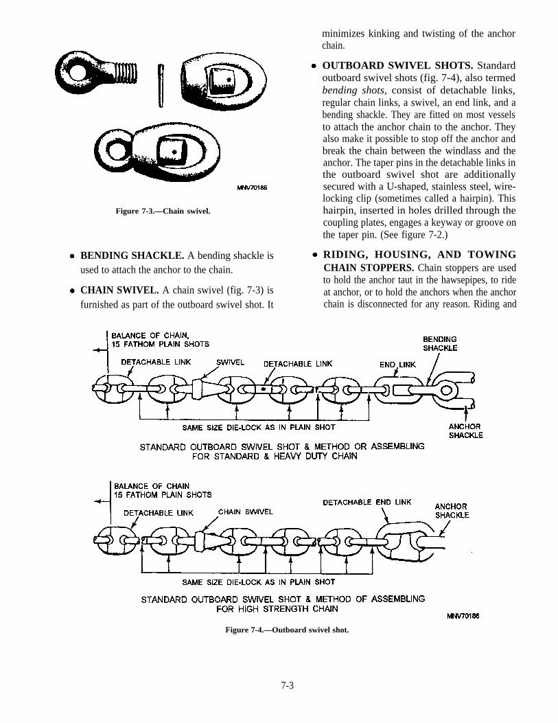
Figure 7-3.—Chain swivel.
BENDING SHACKLE. A bending shackle isused to attach the anchor to the chain.
CHAIN SWIVEL. A chain swivel (fig. 7-3) isfurnished as part of the outboard swivel shot. It
minimizes kinking and twisting of the anchorchain.
OUTBOARD SWIVEL SHOTS. Standardoutboard swivel shots (fig. 7-4), also termedbending shots, consist of detachable links,regular chain links, a swivel, an end link, and abending shackle. They are fitted on most vesselsto attach the anchor chain to the anchor. Theyalso make it possible to stop off the anchor andbreak the chain between the windlass and theanchor. The taper pins in the detachable links inthe outboard swivel shot are additionallysecured with a U-shaped, stainless steel, wire-locking clip (sometimes called a hairpin). Thishairpin, inserted in holes drilled through thecoupling plates, engages a keyway or groove onthe taper pin. (See figure 7-2.)
RIDING, HOUSING, AND TOWINGCHAIN STOPPERS. Chain stoppers are usedto hold the anchor taut in the hawsepipes, to rideat anchor, or to hold the anchors when the anchorchain is disconnected for any reason. Riding and
Figure 7-4.—Outboard swivel shot.
7-3

Figure 7-5.—Chain stopper.
housing chain stoppers (fig. 7-5) consist of aturnbuckle inserted in a short section of chainwith a slip or pelican hook attached to one end ofthe chain and a shackle at the other end. Thehousing stopper is nearest the hawsepipe, theriding stopper is farther aft. These stoppers aresecured by the shackles to permanent pad eyeson the vessel’s deck. When in use, a stopper isattached to the anchor chain by straddling a linkwith the tongue and strongback of the pelicanhook. Special housing chain stoppers, such asthe devil’s claw or the paw1 type of stoppers,normally are used with horizontal windlassesand where space limitations do not permit use ofNavy standard stoppers. Although stoppersalone are more than adequate for holding theanchor, they should be backed up with thewildcat brake. Upon anchoring, you should firstset the wildcat brake band, then set the stopperstight, making sure you equalize the tension onthem, so that one is not loaded more than theother. The wildcat should be left disconnectedfrom the windlass. A Navy standard chainstopper is shown in figure 7-5.
Towing chain stoppers are similar to riding andhousing chain stoppers, except that towing chainstoppers have locking plates added. (See fig. 7-6.)These locking plates prevent the towing chain stopperfrom unscrewing when subjected to the shock loading
Figure 7-7.—Mooring shackles.
Figure 7-8.—Mooring swivel.
of the towing hawser. Towing chain stoppers should beused whenever the ship is being towed.
MOORING SHACKLES. Mooring shacklesare forged steel shackles (fig. 7-7) that are usedto attach anchor chains to mooring buoys. Allmooring shackles, regardless of size, have astandard mortise (opening) of 7 inches. Mooringshackles should not be used for any otherpurposes.
MOORING SWIVELS. Forged steel swivels,with two links attached at each end (fig. 7-8, areused to moor with two anchors. They areinserted in the chain outboard of the hawse andkeep the chain from twisting as the ship swings.Mooring swivels should be attached in the chain
Figure 7-6.—Anchor chain stopper modified for towing.
7-4

Figure 7-9.—Cable jack.
with the eye-end outboard, or down, to preventthem from hooking on the outer lip of the hawsewhen they are heaved back aboard. However,most ships today have large rounded lips on thehawsepipes, making it unlikely that a reversedswivel will catch.
CHAIN CABLE JACKS. A cable jack (fig.7-9), consisting of a lever mounted on an axleand two wheels, is used to handle anchor chain insizes 2 3/4 inches and above. It is used to pick thechain up to pass a chain stopper. A pinch-pointcrowbar type anchor bar is issued for smallersizes of chain.
CLEAR HAWSE PENDANT. A clear hawsependant is a wire rope pendant, 5 to 15 fathomslong, with a thimble at one end and a pelicanhook attached to a length of open-link chainfitted in a thimble at the other end. It is used inclearing a hawse fouled by the anchor chain.(See fig. 7-10.)
DIP ROPE. A dip rope is a fiber rope pendant,fitted at one end with a thimble and a dip shackle
large enough to engage a link of the anchor chainat the other end. This pendant is used to moor orclear a hawse. Information on dip shackles andproportional dimensions for the different sizes ofchain are given in NSTM, chapter 581.
Anchor Chain Markings
The detachable links of anchor chain are paintedred, white, or blue as follows: red, to indicate 15fathoms; white, 30 fathoms; blue, 45 fathoms; red, 60fathoms; white, 75 fathoms; and so on.
At the 15-fathom mark, one link on each side of thedetachable link is painted white, and one turn of wire iswrapped securely around each stud. At the 30-fathommark, two links on each side of the detachable link arepainted white, and two turns of wire are wrapped aroundeach of the last white studs. At the 45-fathom mark,three links on each side of the detachable link arepainted white, and three turns of wire are wrappedaround each of the last white studs. At the 60-fathommark, four links on each side of the detachable link arepainted white, and four turns of wire are wrappedaround each of the last white studs, and so on, for eachshot.
Figure 7-10.—Clear hawse pendant.
7-5

Each link of the entire next-to-last shot is paintedyellow. The last shot is entirely red. These last twoshots are the warning and the danger shots. Theirpurpose is to show you the approach of the chain’s bitterend.
Securing the Bitter End
The bitter end of the anchor chain is secured to a padeye in the chain locker by a safety anchor shackle. Thepad eye, welded to a specially reinforced bulkhead, israted at 1.75 times the breaking strength of the shackle.The strength of the shackle must approximate theweight of 20 shots of anchor chain hanging from thehawsepipe.
CARE OF GROUNDTACKLE
Anchors, chains, and appendages must be kept ingood condition by the ship’s force. This processinvolves the actions described below.
The chain should be overhauled whenevernecessary, with precautions taken to see that the variousshots are properly marked and in good order. As thechain comes in, when a ship is getting under way, eachlink should be examined for cracks and other defects.Two competent observers, preferably petty officers,should be detailed to examine the chain.
Disassembly of detachable links in the outboardswivel shot with hairpins requires removal and probabledestruction of the lockwire. Replacement wire of thesame type should be on hand before the lockwire isremoved. Replacement hairpins can be fabricated onboard ship from corrosion-resistant steel. (See NSTM,chapter 581, or the applicable MRC.)
Anchor chain and its appendages should becarefully examined for cracks, excessive wear,distortion, or other defects. Parts that require coatingshould be painted with anchor chain gloss black paint.(See NSTM, chapter 581.) Shackle bolts, locking pins,and swivels should be examined carefully and put inorder. The turnbuckles in chain stoppers requirefrequent attention to keep them clean, free from rust,and well lubricated with new lubricant.
At least once each 18 months all anchor chain(including shackles, shackle pins, and detachable links)should be examined, overhauled, and placed in a goodstate of preservation. To distribute the wear uniformlythroughout the length of the chain, the shots should beshifted to new positions as necessary during this
inspection. If, during overhaul of the chain, significantdefects are discovered, they should be brought to theattention of the Naval Sea Systems Command. Ifimmediate replacement of a defective shot is notpractical, it should be shifted to the bitter end of thechain.
Recovery of Ground Tackle
When a chain has been slipped or parted, everypossible means must be used to recover both the anchorand the chain. When recovery by the ship’s force isimpossible, the lost anchor and chain should be buoyedand bearings taken of the location of the loss.
ANCHORING AND MOORING
Letting go a single anchor is perhaps the simplestway of securing a ship to the bottom, and when theholding ground is good, the ship should ride easily inbad weather, provided an ample scope of chain is used.One disadvantage of using one anchor is that in a strongcurrent, or in a gale, the ship may sheer, or rotate aboutthe anchor, considerably. Also, when a ship isanchored, it swings to the combined efforts of the windand current. Therefore, it is necessary to have anunobstructed area equal to the length of the ship plus thescope (length) of chain used. If, for some reason, theanchorage does not afford such an area, the ship must bemoored.
A ship is moored when the port and starboardanchors are down at a considerable distance apart andwith enough chain on each anchor that the ship is heldwith its bow approximately midway between them. Aship moored requires an unobstructed area the size of acircle with a radius only slightly larger than the length ofthe ship.
Mooring to a buoy is another way of securing a ship.The buoys are usually anchored with a three-pointmoor. This requires the ship to use only its anchor chainforward and, if it is mooring bow and stem between twobuoys, to also use a mooring line aft. The radius ofswing is limited to the ship’s length and the scope ofanchor chain veered or the area between the twobuoys.
Now that we have discussed anchoring andmooring in general, we will cover the equipment usedand the personnel involved in letting go a single anchor.Mooring with more than one anchor is covered in othertraining manuals for Boatswain’s Mate and in ship-handling books and courses.
7-6

ANCHORING
The ship’s First Lieutenant is in charge on theforecastle while the ship is anchoring and weighinganchor. Aboard most ships, the First Lieutenant’sassistants are the ship’s Boatswain and ChiefBoatswain. In their absence, the senior PO of thedivision responsible for the ground tackle is the FirstLieutenant’s assistant. An EN (Engineman) is present tooperate the anchor windlass, and an EM (Electrician’sMate) must be in the anchor windlass room to take careof any electrical failure. The First Lieutenant has atelephone talker, whose duty is to relay orders andinformation between the forecastle and the bridge. ThePO in charge of the anchor detail musters the detail andensures that all necessary gear is available. SeveralSeamen, whose duties are discussed later, are alsorequired.
Necessary equipment is as follows:
Detachable link toolbox set
Chain stopper wrench
Chain cable jack or anchor bar
Maul
Telephones
Anchor buoy and line
On ships with two wildcats, both anchors are madeready for letting go. While this is being done, thetelephone talker receives from the bridge suchinformation as the anchor to be used, depth of water,type of bottom, scope of chain to be used, and any otherinformation pertinent to the operation.
The exact procedures for making the anchor readyfor letting go may vary, but the following tasks must beperformed: The First Lieutenant or the petty officer incharge must give a safety briefing. All personnelinvolved in the anchoring evolution must be in theproper uniform; that is, with trouser legs tucked in andwearing safety goggles and hard hats with chin straps.Only necessary personnel may be allowed on theforecastle. The Seaman tending the lead line, inaddition to wearing a hard hat, must wear a safetyharness and life jacket. All personnel should be quizzedabout their jobs, and they must be exact in their answers.
The windlass is tested; the anchor in the hawse isfreed. The anchor will be walked out if the ship isanchoring in deep water or if the bottom is rocky;otherwise, the brake is set and the wildcat is disengaged.
All but one stopper is taken off, and the anchor buoy isshackled to the chafing chain or pendant. The chainlocker is checked for any loose gear that may becomewedged in the chain pipes or come flying out,endangering the personnel on deck.
While the anchor detail gets the ground tackleready, the Quartermasters on the bridge take bearings,and the navigator plots the bearings on a chart andadvises the conning officer of the ship’s position.Distances to the anchorage are relayed to the forecastle.
In letting go by the stopper, the weight of the anchormust be on the stopper. The brake will be released onthe command “STAND BY”.
In letting go by the brake, the weight of the anchorwill be on the brake and the stopper with the windlassdisengaged. The stopper will be taken off at thecommand “STAND BY”.
At the command “STAND BY”, the personnel onthe forecastle are alert and ready, awaiting the nextcommand. When letting go by the stopper, two Seamantake stations at the stopper. When the command “LETGO” is given, one Seaman pulls the pin from the stoppertongue. The other Seaman, with a maul, knocks the bailoff the tongue of the pelican hook and steps clear, andthe chain will pass through the hawse with a roar.
If the anchor buoy was not stopped off with sailtwine, the Seaman tending it must let it go exactly at thecommand “LET GO”. On the bridge, the anchor ball ishoisted. The flag is hauled down from the truck, and thejack and ensign are hoisted smartly fore and aft.
You will notice that the ship is moving (usuallybacking) when the anchor is dropped. This keeps theanchor chain from piling on itself, damaging the chain,or piling on or fouling the anchor.
When the anchor is dropped and hits bottom, thebrake should be set to help prevent piling. Reports aremade to the bridge informing them on the initial statusof the anchor, how much chain is out, what position ittends, and what strain it has on it. The bridge is alsoinformed of whether the anchor buoy is watching. (Thismeans that the buoy has surfaced and marks the locationof the anchor.) As the ship gains sternway, the anchorchain is veered out by the brake about a shot at a time tocontrol the speed of the chain. This is continued untilsufficient chain is out to ensure that the pull on theanchor is horizontal on the bottom. The brake is nowapplied, and the anchor is set by the ship’s backing downand riding on the chain. Once the anchor is set and
7-7

holding, the brake is taken off, and the chain is veered tothe desired scope.
As each chain marking passes the wildcat, thereport “(Number) fathoms on deck’ is made to theconning officer. The direction the chain is tending isindicated by pointing the arm and/or reporting “Chaintending (number) o’clock”. Depending on thepreference of the commanding officer, the way reportsare given may vary from ship to ship. These reportsenable the conning officer to maneuver the shipproperly.
When the desired scope of chain is out, the order“PASS THE STOPPERS” is given. The brake is set,and the stoppers are applied and evened up. The brake istaken off; then the chain is slacked between the windlassand the stopper. The brake is set, and the wildcat is leftdisengaged. Before the anchor detail is secured, all gearmust be picked up and stowed.
Scope of Chain
Under normal conditions, a ship usually anchors toa scope of chain between five and seven times the depthof the water. This is important to prevent losing theanchor or the anchor and part of the chain in heavyweather. When a ship at anchor is subjected to heavy
weather, a strain much stronger than normal is placed onthe chain. More and more of the chain’s length lifts offthebottom as the strain increases. When the scope is notlong enough, the chain lifts all the way to the shank, andthe anchor breaks out and drags before the chain parts.With too long a scope, however, the breaking strain ofthe chain is reached and the chain parts before its entirelength lifts off the bottom.
Weighing Anchor
When the ship is weighing anchor, the same gearand personnel should be available on the forecastle asfor anchoring. In addition, there must be a grapnel forretrieving the anchor buoy, and a saltwater hose must berigged to wash the mud from the chain and the anchor.
The following procedures are carried out in makingready for weighing anchor. After the windlass isenergized, the anchor windlass is tested. Then thebrake is set, and the riding stopper is cast off and clearedfrom the chain. The anchor is now engaged, held by thebrake and backed up by the housing stopper. Wheneverything is ready, the report “Ready to heave in” ismade to the bridge.
The ship will be riding on its anchor chain, as shownin view A of figure 7-11. If the wind or current is strong,
Figure 7-11.—A ship from anchored to under way.
7-8

the conning officer may put on enough turns (screwturns) to take the strain off the ground tackle.
On the command “HEAVE AROUND”, the brakeis taken off and the chain is heaved in enough to take thestrain off the stopper. The stopper is cast off, andheaving around is resumed. Reports are made to thebridge periodically on the direction that the chain istending, the amount of chain out, and what kind of strainis on the chain.
If the command were “HEAVE AROUND TOSHORT STAY”, the chain would be heaved in just shortof breaking out the anchor, as seen in view B of figure7-11. The bridge is notified when the chain is at shortstay.
When the command “HEAVE AROUND ANDUP” is given, the chain will be heaved in. When theflukes of the anchor have broken out and the crown stillrests on the bottom, the bridge is notified “Anchorbreaking ground”, and then “Anchor is up and down”,as seen in view C of figure 7-11.
When the anchor is free from the bottom, the bridgeis notified “Anchors aweigh”, as seen in view D offigure 7-11. The jack, ensign, and anchor ball will behauled down, and the underway ensign hauled smartlyto the truck.
When the anchor comes into view and its conditioncan be noted, the report “Anchor in sight” is made. Withthis report, the bridge is told if the anchor is clear,fouled, or shod (meaning caked with mud and bottom).
The anchor is reported as housed when the shank isin the hawsepipe and the flukes are against the ship’sside. The anchor buoy is recovered as soon as possible,and the report is made to the bridge when the anchorbuoy is on board.
The anchor is again made ready for letting go andkept that way until the anchor detail is told to secure itafter the ship is outside the harbor or channel.
To secure the anchor for sea, the brake is set; thenthe stoppers are passed and evened up (meaning thatthey take equal strain). The brake is taken off; then thechain is slacked between the wildcat and the stopper.The brake is set and the wildcat is disengaged. Toprevent water from entering the chain locker, thebuckler plates are secured over the chain pipes (on someships, canvas chain pipe covers go over the plates).
MOORING TO A BUOY
When the ship is about 1,000 yards from themooring buoy, a boat containing a buoy party of three or
four personnel, in addition to the boat’s crew, is loweredto the water. All hands in the boat must wear life jacketsand must be qualified second class swimmers.
The ship is maneuvered so it will come to a stopwith the bow directly over the buoy. The boat comesalongside the buoy and two members of the buoy partyget on the buoy. Then the crew members intheboat takefrom the ship the ends of the dip rope, a messenger, anda mooring/buoy wire with a mooring shackle that islarge enough to engage the ring on the buoy. Theshackle pin is secured to the shackle with a lanyard toprevent its loss. The wire is shackled to the ring, and thedip rope is passed through the ring and tied to themessenger. Then the crew gets back into the boat, andthe boat clears the buoy.
Meanwhile, these mooring preparations are madeon the forecastle: The anchor is disconnected, and themooring shackle is secured to the anchor chain. The diprope is fastened to the chain a short distance above theshackle. The other end of the dip rope is pulled backaboard by means of the messenger and is taken to thecapstan In the meantime, the mooring/buoy wire isheaved taut. The mooring/buoy wire serves to hold thebow of the ship in position. The mooring shackle ispulled into position by walking out the chain andheaving around on the dip rope. The buoy party againgets on the buoy and secures the shackle to the ring.Then the mooring/buoy rope is slacked off, unshackled,and the moor is complete.
Trolley Method
The trolley method of mooring to a buoy is a simpleand rapid means of easing the bitter end of the chain(controlled by an easing-out line) down to the mooringbuoy by letting it slide on the wire shackled to the buoy.(See fig. 7-12.)
Figure 7-12.—Trolley method.
7-9

One or more large shackles over the buoy wireserve as trolleys. The chain is connected to the trolley bya short wire strap passed around the stud of a link nearthe bitter end. Enough chain must hang free to allow itto be shackled easily to the mooring ring. Connecting itto the fourth or fifth link usually provides the properamount of free-hanging chain. Other preparations ondeck are much the same as for the ordinary method ofmooring to a buoy, except that sufficient chain for themaneuver is roused up and allowed to hang in a bightover the side during the approach, and it is not necessaryto use a dip rope. The easing-out line, in addition tocontrolling the travel of the chain during the mooringoperation, prevents the bitter end of the chain fromdropping into the water during the approach.
When the ship is mooring by the trolley method, thebuoy party in the boat takes only the end of the wire tothe buoy. The wire is either shackled directly to the ringof the buoy, or a short wire strap is passed through thering and the eye of the wire, and the ends of the strap areshackled together. The buoy party is always providedwith a strap when the size of the ring on the buoy isunknown. If possible, the buoy wire is connected to aring other, than the one to which the chain will beshackled.
The ship is maneuvered to bring the bullnoseabreast of the buoy and about 10 yards away. Once thebuoy wire is secured, it is heaved taut and kept that way.The chain is allowed to slide down the wire by slackingoff the easing-out line, and the mooring shackle issecured to the ring of the buoy by the buoy party. Thewire is then slacked and cast off, completing the moor.
On ships with unusually large and heavy chain, twoor more trolleys should be used, and it is a good idea topass a line from the deck, through the ring of the buoy,and to secure it to the mooring shackle or the first link.Then, by using this line and the easing-out line, thepersonnel on deck are able to assist the working party onthe buoy to get the mooring shackle into position.
Bow and Stern Buoy Moor
The bow and stem buoy moor is used by all navies.It is used throughout the world where the harbors aresmall and congested or in areas where ships are out ofservice.
In this type of moor, the ship’s bow is moored to theforward buoy in either manner described above. At thesame time, a stem line or cable is run to the stem buoy.The ship approaches at an angle of about 20° to thegeographical line-of-bearing of the two buoys. Whilelines are being passed to the bow buoy party, similar
lines are passed from the ship by boat to the stem buoyparty. After the lines are made fast to the buoys,adjustments are made from on deck to spot the shipequidistantly, bow and stern, from the respective buoys.Most ships use an anchor chain forward and a nylontowing hawser or a wire rope aft.
Slipping a Mooring
For this maneuver, a strong line or flexible wire isrun through the buoy ring and back on deck for use as aslip rope. A strain is taken on it, and the chain isunshackled. Should the ship be riding to a bight of thechain, an easing-out line is used to ease the chainthrough the ring while the chain is being hauled in. Theship now rides to the slip rope, and unmooring iscompleted by letting the end of the slip rope go andreeving it through the buoy ring.
TOWING
All naval vessels are required to be able to tow andbe towed. Equipment varies with the types of ships, andprocedures vary with the circumstances. Equipmentused, as well as procedures for towing and being towed,is listed in the ship’s towing bill.
RIGGING FOR TOWING OR BEINGTOWED
To describe every towing rig would be impractical,so we have limited our description of rigging foremergency towing to the standard synthetic gear andsome parts of the wire rigs.
NAVSEA provides the latest guidance concerningauthorized synthetic towing hawsers and end fittings.The preferred towline is a nylon rope of nonrotatingconstruction that is either plaited or double-braided.These lines must have a minimum breaking strengthwithin 10 percent of the breaking strength of theemergency tow hawser shown in the ship’s plans.NAVSEA does not recommend the use of swivels withany of these towlines.
The towing gear consists of reinforced structurepoints (referred to here as hard points), a chafing chain,a towing hawser, and connectors. On the towed ship,the chafing chain and hard points are usually made upfrom the ship’s anchor chain and chain stoppers fair-ledthrough the bow chock. A typical arrangement is shownin figure 7-13. On the towing ship, the hard point isprovided by a towing pad which is usually located onthe centerline, although it is sometimes found on thequarter because of equipment interference. A section ofchafing chain is connected to the pad by a pelican hook,
7-10

Figure 7-13.—Typical bow chafing chain arrangement for being towed.
which is used for dropping the tow in case ofemergency. The other end of the chafing chain is fair-led through a closed chock on the stern. A typicalarrangement is shown in figure 7-14. Since it is logicalto assume that the reason a ship has to be towed isbecause it has lost power, the rigging arrangementaboard the ship to be towed must be laid out so no powerassistance is required. Therefore, practice operationsshould be performed with the towed ship using nopower equipment.
Towed-Ship Rigging Procedure
The towed ship rigs for being towed by breaking theanchor chain inboard of the swivel shot. The anchor notin use is secured in the hawsepipe by a chain stopper anda preventer made of wire. The wildcat brake is set up.When the chain pipe has a compressor, it is used to keepthe chain from falling back into the chain locker; whenthere is no compressor installed, a bar through the chainand across the chain pipe can substitute for thecompressor. The chain is then moved over in alignmentwith the bow chock It will be hauled through the bowchock later by the towing hawser as a strain is taken onthe hawser by the towing ship. The connector fittingsare standard rigging and detachable links of the size ofchain being used. The towing hawser is either wire,whose size and length satisfy the ship’s plans, orsynthetic hawser 600 feet long. Attached to the hawseris a messenger made up of 100 fathoms of 3-inch lineand 50 fathoms of 1 1/2-inch line. (For a lo-inchcircumference or larger hawser, use the 4-inch in placeof the 3-inch.) Two 100-fathom lengths of 6-thread or9-thread line are attached to the 1 1/2 line and runoutboard on both sides of the ship. Then the 6-thread
line is attached to the shot line, reducing the weight onthe shot line while the messenger is passed to thereceiving ship. The hawser and messenger are faked outand stopped off to a strongback, with turns of 21-threadline running over a chop block to provide constantcontrol while the hawser is paid out. These stops are cuton command as the hawser pays out. A retrieval line isconnected to the anchor chain end of the towing opera-tion to retrieve the towing hawser. The same procedureis followed on the towing ship, except that the pelicanhook is rigged to the hard point, and the chafing chain tothe pelican hook, fair-led out the stem chock. You willnotice that we have referred to the ship to be towed asbeing the provider of the rig. Which ship ultimatelyprovides the initial hawser is a command decision, andcircumstances will be different in each case.
Figure 7-14.—Typical stern chafing chain arrangement for
towing.
7-11

When both ships’ hawsers are used to increase thelength of the tow to 1,200 feet (fig. 7-15, one ship willhaul in the other’s hawser and connect the two hawserstogether with a pear-shaped detachable link, then payout the hawser as the other ship goes ahead, taking upthe slack as it goes, until all the hawser is out. Whenonly one ship’s hawser is, the ship receiving the other’shawser connects it to either the anchor chain, brokenforward, or the chafing chain, rigged aft.
The messenger is secured to the towing hawser asshown in figure 7-16, view A; or if a wire hawser is to beused, it may be modified as in view B. If desired, a thirdmethod may be used; that is, a strap is eye-spliced, as anextension to the messenger, and a shackle used to makethe connection between the messenger and strap, whichis secured to the hawser as in view A.
Approaching the Tow
The position the towing ship takes in relation to thetow during the approach depends on which vessel driftsfaster. When the towing ship drifts faster than the tow,the towing ship takes position forward and to windwardWhen the tow drifts faster, the towing ship takesposition ahead and to leeward. The idea is that one shipdrifts past the other, allowing more time for passing andhooking up the towline. The towing ship alwaysensures there is plenty of room to maneuver. If a normalclose approach cannot be made, because of seaconditions, the towline messenger may have to bebuoyed with life jackets and floated down to the tow.Often, however, the approach is close enough to useheaving lines, so there should be three or four heavinglines on deck, as well as a line-throwing gun and bolos.
Figure 7-15.—Towing hawser arrangement.
7-12

Figure 7-16.—Method of securing messenger to towline.
Passing the Rig
The end of the towline messenger is passed as soonas possible to the towing ship. During the approach,personnel on the towing ship are stationed at intervalsalong the deck to receive the towline messenger. Oncethe messenger is received, the end is led through thestem chock and run forward. You may take themessenger to a capstan, but this method is much slowerthan heaving it in by hand until a heavy strain is taken.The final hauling of the towing hawser is usually doneby the capstan. Once the end of the towing hawser isaboard, the seizing that secures the coupling to themessenger is cut, and the towed ship’s hawser isconnected to your hawser. A stopper is bent onto thehawser; the messenger is removed; and the towlines arehooked up but not yet deployed. The towing ship putson turns sufficient for steerageway and continues at thissteady speed until the towline is completely taut. Thisslow speed deploys the towline off the towing ship, in aslow orderly fashion, until all the faked out line is off thedeck and the chafing chain has been hauled through thestem chock.
The added tension hauls the remaining towline offthe towed ship until its anchor chain comes taut. At thispoint, the bar is removed from the chain over the chain
pipe and the brake on the wildcat is slackened. Thechain is permitted to be hauled out until it clears the bowchock by 6 or more feet. The brake is applied and twotowing chain stoppers are passed onto the chain.
While a ship is towing, an emergency releasecapability is required. The chain is veered out to the firstdetachable link and the stoppers are passed forward ofthe detachable link. This will provide access to the linkin case the tow must be released.
Getting in Step
When a ship is towing with synthetic line, nocatenary (line droop) is required. It is not uncommon tohave the hawser completely out of the water; in fact, it isdesirable because it lowers the towing resistance andprevents the line from being damaged by bottomfouling or objects in the water. When heavy seas areencountered, the rule is slow down. At this point, it isimportant to keep the ships in step to lessen the surgeloads. To do this, cast off the stoppers, and adjust thescope to get the vessels in step. The tow must ride sothat it reaches the top of a crest at the same time thetowing ship does. If not, the towing ship might reach thecrest while the tow is in a trough, whipping the towlineout of the water and subjecting it to unnecessary and
7-13

dangerous strains. (See fig. 7-17.) When the scope isadjusted properly, the chain is secured in the same wayas before.
Dropping the Tow
When the ships are dead in the water and the order isgiven, the tow engages its wildcat, casts off the stopper,and heaves in on the chain. When the end of the towlineis aboard, the messenger is bent on the towline. Turnsare taken around the capstan with the messenger, andthe chain is walked out until the strain is on themessenger. Then the towline is unshackled and easedout. Personnel on the towed ship run in the towline bycapstan or hand. Care must be taken on the towing shipthat the catenary does not become too heavy for thecrew on the towed ship to handle.
When a recovery line is rigged on the towing ship,the end of it is led through the towing chock fromoutboard to inboard and hauled in by hand (or, ifnecessary, by power) until the chafing chain and theinboard end of the towline are aboard. Then the towlineis hauled the rest of the way in.
SALVAGE
The term salvage covers everything from refloatingstranded vessels to wreck removal. World War IIprovided a prime example of the value of salvageoperations. The U.S. Navy salvage organization duringthis period salvaged and reclaimed ships and equipmentworth over 2 billion dollars.
PRINCIPAL TYPES OFSALVAGE
It is, of course, impossible to place all wrecks into aneat category. Nearly all will fall within one of fourprincipal types of salvage. The types of salvage are:
RESCUE SALVAGE. Rescue salvage providesemergency salvage services to vessels andaircraft in distress at sea. The most importantservice is towing damaged ships to a safe harbor.Fire fighting, pumping, and minor patching alsoare services a salvage ship can render in anemergency. Major problems are storms andgales, fire, collision, machinery failure, shifting
Figure 7-17.—Examples of out-of-step and in-step during towing.
7-14

cargo, loss of rudder or propeller, and battledamage.
HARBOR SALVAGE. Harbor salvage consistsof salvaging ships, removing wreckage, andgeneral salvage work in harbors. Collision is thechief cause of damage to ships in a harbor. Aftera collision, either one or both ships may be sunkor beached. One of the ships may sink in themain channel, blocking the channel completely;or it may sink alongside the best pier, preventingcargo unloading. You can be sure of one thing,the Navy will be called upon to provide a salvageship or salvage team. (In wartime, salvage teamsare activated.)
Weather is another major enemy to ships in aharbor. Often a storm strikes without warning, catchingharbor craft and barges with single lines out and shipsanchored with insufficient chain. The results arebeached barges, sunken harbor craft, and strandedships.
Another feature of harbor salvage is harborclearance away from the combat area. A great deal ofthis type of salvage was performed during World War II.
OFFSHORE SALVAGE. Offshore salvage isconcerned with refloating vessels stranded orsunk in exposed locations along a coast.Strandings occur as the result of many factors,such as weather, errors in navigation, poorseamanship, improper ship handling, andengineering problems.
COMBAT SALVAGE. Combat salvageconsists of services rendered to an amphibiousassault force and is not limited to salvage alone.These services are performed by a combatsalvage group composed of one or more salvageteams and salvage vessels of all types. Thisgroup is manned and equipped to rescuepersonnel, retrieve stranded craft from the beach,make emergency repairs ashore or afloat, fightfires, give emergency supplies, aid in damagecontrol afloat, tow disabled craft, performunderwater surveys, and do general repair work.
7-15
