and atm (asynchronous transfer mode) …...based on circuit switching -> leased line • based on...
TRANSCRIPT

Datenkommunikation 384.081 - SS 2012
L05 - Legacy Network Technologies (v5.1)
© 2012, D.I. Lindner / D.I. Haas
Page 05 - 1
Legacy Network Technologies
Introduction to ISDN, X.25, Frame Relayand ATM (Asynchronous Transfer Mode)
Datenkommunikation 384.081 - SS 2012
L05 - Legacy Network Technologies (v5.1)
© 2012, D.I. Lindner / D.I. Haas
Page 05 - 2
© 2012, D.I. Lindner / D.I. Haas Legacy Network Technologies, v5.1 2
Agenda
• ISDN
• X.25
• Frame Relay
• ATM

Datenkommunikation 384.081 - SS 2012
L05 - Legacy Network Technologies (v5.1)
© 2012, D.I. Lindner / D.I. Haas
Page 05 - 3
© 2012, D.I. Lindner / D.I. Haas Legacy Network Technologies, v5.1 3
Why ISDN (Integrated Services Digital Network)?
• During the century, Telco's– Created telephony networks
• Originally analog end-to-end using SDM
• Later digital backbone technology (PDH, SDH, SS7)– Still analogue between telephone and local exchange
– Created separate digital data networks• Based on circuit switching -> leased line
• Based on packet switching -> X.25
• Today: Demand for various different services– Voice, fast signaling, data applications, real-time
applications, video streaming and videoconferences, music, Fax, ...
– All digital world
Why has ISDN (Integrated Services Digital Network) been invented and what is its basic idea? Originally there were two types of Telco networks: one for voice and one for data. Since both traffic types are totally different in behavior it was reasonable to implement two different technologies. Basically, synchronous techniques were used for voice and asynchronous protocols (X.25) were used for data.
Later additional traffic types appeared, such as voice and video streaming, various realtime applications, and so on. Today we call these traffic types "services".
The inventors of ISDN proposed one single network to transport all these services in order to reduce complexity, increase maintainability, improve scalability—and basically to safe money.
Datenkommunikation 384.081 - SS 2012
L05 - Legacy Network Technologies (v5.1)
© 2012, D.I. Lindner / D.I. Haas
Page 05 - 4
© 2012, D.I. Lindner / D.I. Haas Legacy Network Technologies, v5.1 4
What is ISDN?
• ISDN is the digital unification of the telecommunication networks for different services– Offers transport of voice, video and data
• Offers digital telephony to the end system too
– All-digital interface at subscriber outlet
• N-ISDN ensures world wide interoperability– Standardized user-to-network interface (UNI)
• BRI (Basic Rate Interface)
• PRI (Primary Rate Interface)
N-ISDN means Narrowband-ISDN, but you can also think of "Normal-ISDN". The planning of ISDN began already in 1976, but real-world applications became available only with the mid-80's. Also Frame-Relay is regarded as part of the ISDN family, because it can be transported upon the physical layer of ISDN, which we will discuss soon.
ISDN specifies only a User to Network Interface (UNI)—quite similar than X.25 and Frame Relay. But the main difference is that ISDN relies on deterministic, synchronized multiplexing.
Two data rates were defined: The Basic Rate Interface (BRI) and the Primary Rate Interface (PRI). Both are explained on the next pages in more detail.
Synchronous and deterministic multiplexing provides constant delays and bandwidth. Therefore, a user can able to put any type of traffic upon this layer—it works fully transparent!
The connections are established dynamically by a signaling protocol. The user dials a number and a temporary connection is created. The signaling protocol is the famous "Q.931". It is explained later but you should try to memorize it even by now.

Datenkommunikation 384.081 - SS 2012
L05 - Legacy Network Technologies (v5.1)
© 2012, D.I. Lindner / D.I. Haas
Page 05 - 5
© 2012, D.I. Lindner / D.I. Haas Legacy Network Technologies, v5.1 5
Technical Overview
• Implementation of a circuit switching– Synchronous TDM
– Constant delay
– Constant bandwidth
– Protocol-transparent
• Dynamic connection establishment– User initiated
– Temporarily
– Signaling Protocol • Q.931 between end-system and local exchange
• SS7 between local exchanges
Synchronous and deterministic multiplexing provides constant delays and bandwidth. Therefore, a user can able to put any type of traffic upon this layer—it works fully transparent!
The connections are established dynamically by a signaling protocol. The user dials a number and a temporary connection is created. The signaling protocol is the famous "Q.931". It is explained later but you should try to memorize it even by now.
Datenkommunikation 384.081 - SS 2012
L05 - Legacy Network Technologies (v5.1)
© 2012, D.I. Lindner / D.I. Haas
Page 05 - 6
© 2012, D.I. Lindner / D.I. Haas Legacy Network Technologies, v5.1 6
ISDN User-to-Network Interface (UNI)
ISDN-TE
ISDNNetwork Service
physical access link(I.430, I.431)
ISDN-LE
channelfor user data(B-channel)
channelfor signaling(D-channel)
(Q.921, Q.931)
…
logical channels multiplexed on physical channel
TE … Terminal Equipment (ISDN end system)LE … Local Exchange (ISDN switch)
Datenkommunikation 384.081 - SS 2012
L05 - Legacy Network Technologies (v5.1)
© 2012, D.I. Lindner / D.I. Haas
Page 05 - 7
© 2012, D.I. Lindner / D.I. Haas Legacy Network Technologies, v5.1 7
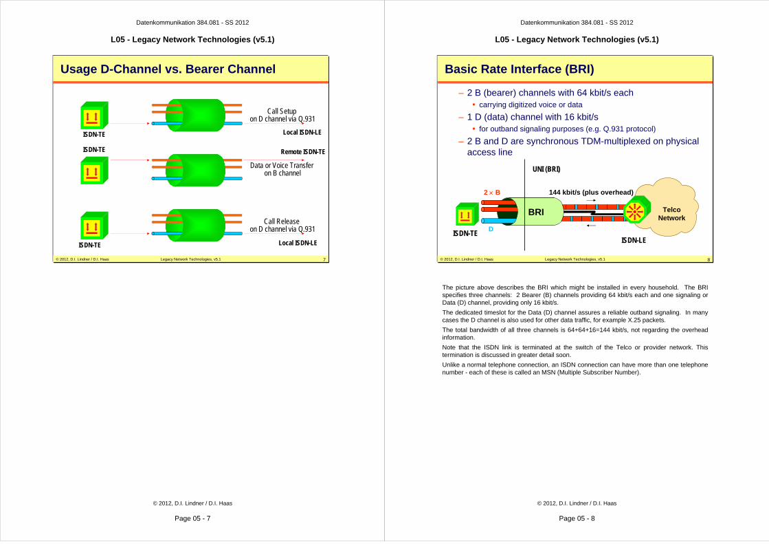
Call Setup on D channel via Q.931
Data or Voice Transfer on B channel
Call Release on D channel via Q.931
Usage D-Channel vs. Bearer Channel
ISDN-TE Local ISDN-LE
ISDN-TE Remote ISDN-TE
ISDN-TE Local ISDN-LE
Datenkommunikation 384.081 - SS 2012
L05 - Legacy Network Technologies (v5.1)
© 2012, D.I. Lindner / D.I. Haas
Page 05 - 8
© 2012, D.I. Lindner / D.I. Haas Legacy Network Technologies, v5.1 8
Basic Rate Interface (BRI)
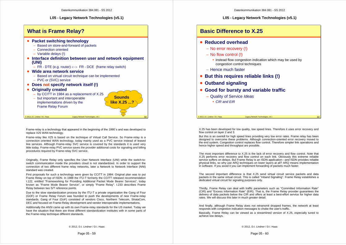
– 2 B (bearer) channels with 64 kbit/s each• carrying digitized voice or data
– 1 D (data) channel with 16 kbit/s • for outband signaling purposes (e.g. Q.931 protocol)
– 2 B and D are synchronous TDM-multiplexed on physical access line
BRI
2 × B
D
TelcoNetwork
144 kbit/s (plus overhead)
ISDN-TEISDN-LE
UNI (BRI)
The picture above describes the BRI which might be installed in every household. The BRI specifies three channels: 2 Bearer (B) channels providing 64 kbit/s each and one signaling or Data (D) channel, providing only 16 kbit/s.
The dedicated timeslot for the Data (D) channel assures a reliable outband signaling. In many cases the D channel is also used for other data traffic, for example X.25 packets.
The total bandwidth of all three channels is 64+64+16=144 kbit/s, not regarding the overhead information.
Note that the ISDN link is terminated at the switch of the Telco or provider network. This termination is discussed in greater detail soon.
Unlike a normal telephone connection, an ISDN connection can have more than one telephone number - each of these is called an MSN (Multiple Subscriber Number).

Datenkommunikation 384.081 - SS 2012
L05 - Legacy Network Technologies (v5.1)
© 2012, D.I. Lindner / D.I. Haas
Page 05 - 9
© 2012, D.I. Lindner / D.I. Haas Legacy Network Technologies, v5.1 9
Primary Rate Interface (PRI)
– 30 B (Bearer) channels with 64 kbit/s each (USA 23 B)
– 1 D (Data) channel with 64 kbit/s• for signaling purposes (e.g. Q.931 protocol)
– 30 B and D are synchronous TDM-multiplexed on one physical access line
30 × B
D
PRI 2.048 Mbit/s(E1 Frames)
ISDN-TEISDN-LE
UNI (BRI)
The PRI also contains B and D channels, but now there are 30 B channels and also the D channel has the same bandwidth of 64 kbit/s. These 31 channels plus an additional synchronization channel result in a total data rate of 2,048 Mbit/s, which is transported over a E1 frame (basic component of PDH hierarchy).
Note: In USA and Japan the ISDN PRI offers a data rate of 1.544 Mbit/s.
Datenkommunikation 384.081 - SS 2012
L05 - Legacy Network Technologies (v5.1)
© 2012, D.I. Lindner / D.I. Haas
Page 05 - 10
© 2012, D.I. Lindner / D.I. Haas Legacy Network Technologies, v5.1 10
ISDN Services
• CCITT defined three services– Bearer services (Circuit or Packet)
– Teleservices (Telephony, Telefax, ...)
– Supplementary services• Reverse charging
• Hunt groups
• etc...
The CCITT (today known as ITU-T) defined three services for ISDN..
Bearer services define transport of information in real time without alteration of the content of the message. Both circuit mode and packet mode (virtual call and permanent virtual circuit) is supported.
Teleservices combine transportation function with information-processing functions, e.g. telephony, teletex, telefax, videotex, and telex.
Supplementary services can be used to enhance bearer or teleservices. Examples for supplementary services are reverse charging, closed user group, line hunting, call forwarding, calling-line-identification, multiple subscriber number (MSN), and subaddressing.

Datenkommunikation 384.081 - SS 2012
L05 - Legacy Network Technologies (v5.1)
© 2012, D.I. Lindner / D.I. Haas
Page 05 - 11
© 2012, D.I. Lindner / D.I. Haas Legacy Network Technologies, v5.1 11
Functional Groups
• Terminal Equipment (TE)– TE1 is the native ISDN user device
(phone, PC-card, ...)
– TE2 is a non-ISDN user device(Analog telephone, modem, ...)
• Network Termination (NT)– NT1 connects TEs with ISDN
– NT2 provides concentration and supplemental services (PBX)
• Terminal Adapter (TA)– TA connects TE2 with NT1 or NT2
Several "functional groups" have been specified to differentiate technical capabilities. An end device is called a "Terminal Equipment" (TE).
A TE1 is a true ISDN device such as an ISDN telephone.
A TE2 is any non-ISDN device that can be attached to the ISDN interface via a Terminal Adapter (TA).
A NT1 connects the 4 wire TE1 to the 2 wire ISDN link to the Telco switch, also known as Local Exchange (LE).
A NT2 is an optional device that provides concentration of multiple local premises phone lines and connection to the LE. This device is also called a Private Branch Exchange (PBX) and might provide a lot of additional services, depending on the vendor.
Datenkommunikation 384.081 - SS 2012
L05 - Legacy Network Technologies (v5.1)
© 2012, D.I. Lindner / D.I. Haas
Page 05 - 12
© 2012, D.I. Lindner / D.I. Haas Legacy Network Technologies, v5.1 12
Reference Points
• Logical interfaces between functional groups– R connects PSTN equipment with TA
– S connects TEs with NT2
– T connects NT2 with NT1
– U connects NT1 with Exchange Termination (ET)
Besides the Functional Groups, also "Reference Points" had been specified. Reference Points identify logical interfaces between the previously mentioned Functional Groups.

Datenkommunikation 384.081 - SS 2012
L05 - Legacy Network Technologies (v5.1)
© 2012, D.I. Lindner / D.I. Haas
Page 05 - 13
© 2012, D.I. Lindner / D.I. Haas Legacy Network Technologies, v5.1 13
Reference Diagram (BRI)
TA
NT1
Up to 8 TEs
TE1
TE1
TE2
LT ET
ISDN Switch
VUS/T
R
Phone Company
Home
Termination point in Europe
Termination point in USA
LT Line TerminationET Exchange TerminationTA Terminal AdapterTE Terminal EquipmentNT Network Termination
2 Wires4 Wires
ISDN LE
A TE2 is for example a plain old telephone (POT) or an analog modem. The R interface is typically a EIA/TIA-232-C, V.24, or V.35.
Basically, the NT1 converts the U to S/T interface: 2 wires to 4 wires, different coding scheme, different bit-rates (160 to 192 bit/s). Furthermore the NT1 cares for synchronization, multiplexing of B and D channels, and optional power provision for TEs. Some people just call it ISDN-modem. Never say that.
Datenkommunikation 384.081 - SS 2012
L05 - Legacy Network Technologies (v5.1)
© 2012, D.I. Lindner / D.I. Haas
Page 05 - 14
© 2012, D.I. Lindner / D.I. Haas Legacy Network Technologies, v5.1 14
Reference Diagram (PRI)
NT1 LT ETVU
Phone Company
Company
NT2 TS
PBX
.
.
.
.
.
Can be a single device
ISDN SwitchISDN LE
The picture above shows the principle of a PRI installation, using a PBX (NT2) which terminates all local telephones. Note that these telephones are not necessarily ISDN compliant telephones. Rather vendor proprietary technologies are used here.

Datenkommunikation 384.081 - SS 2012
L05 - Legacy Network Technologies (v5.1)
© 2012, D.I. Lindner / D.I. Haas
Page 05 - 15
© 2012, D.I. Lindner / D.I. Haas Legacy Network Technologies, v5.1 15
U-Interface
• Recommendation G.961– 160 kbit/s (remaining capacity used for framing and
synchronization)
• Either echo cancellation or time compression (ping-pong)
• 2B1Q (ANSI T1.601)– -2.5 V, -0.833 V, +0.833 V, +2.5 V
– Requires half the BW of NRZ
– Plus scrambling for synchronization and uniform PSD distribution
The U-interface is defined in CCITT "Recommendation G.961" and specifies a 160 kbit/s transmission method over two wires. Bidirectional communication is provided either by echo cancellation or "ping-pong" transmission, i. e. alternating sending and receiving of both sides within short time periods.
"Two Binary One Quaternary" (2B1Q) digital coding is used on this interface.
Datenkommunikation 384.081 - SS 2012
L05 - Legacy Network Technologies (v5.1)
© 2012, D.I. Lindner / D.I. Haas
Page 05 - 16
© 2012, D.I. Lindner / D.I. Haas Legacy Network Technologies, v5.1 16
I.430I.431
Q.921(LAPD)
Q.931
UserSpecified
I.430I.431
Q.921(LAPD)
Q.931
Control-Plane(D channel)
User-Plane(B channel)
User-Plane(B channel)
Control-Plane(D channel)
User Network
S/T
1
2
UserSpecified
ITU-T ISDN Layers (“Protocol Stack”)
User-Network-Interface(UNI)
3
The diagram above shows the ISDN layer model. There is one common physical layer, which is either I.430 (the BRI) or I.431 (the PRI). Note the vertical separation above the common physical layer - a clear sign of outband signaling!
On the left side the signaling protocol Q.931 can be identified in this diagram. This "Control Plane" protocol carries the dial numbers and is itself carried by Q.921, a HDLC variant providing a reliable delivery of data between two adjacent interfaces between TE and LE.
On the right side the "User Plane" is specified as an open interface. That is, the user can put any service directly upon the synchronous physical layer.
Concerning to the OSI model you can see that there is no clear indication where ISDN is located. If a B channel is established then ISDN looks for the user as OSI L1 (physical layer) technology at the User-Plane. But in order to establish a B channel you need protocols in the Control-Plane. ISDN defines Q.921 (LAPD) at OSI L2 (data link layer) and Q.931 at the higher OSI layer. Q.931 looks like the application layer in these case because Q.931 is primarily a signaling protocol and has nothing to do with OSI L3 (network layer). You see applying the OSI model to the real world is not so easy.

Datenkommunikation 384.081 - SS 2012
L05 - Legacy Network Technologies (v5.1)
© 2012, D.I. Lindner / D.I. Haas
Page 05 - 17
© 2012, D.I. Lindner / D.I. Haas Legacy Network Technologies, v5.1 17
I.430I.431
Q.921(LAPD)
Q.931
UserSpecified
I.430I.431
Q.921(LAPD)
Q.931
Control-Plane(D channel)
User-Plane(B channel)
User-Plane(B channel)
Control-Plane(D channel)
User Network
S/T
1
2
UserSpecified
ITU-T ISDN Physical Layer
User-Network-Interface(UNI)
3
Datenkommunikation 384.081 - SS 2012
L05 - Legacy Network Technologies (v5.1)
© 2012, D.I. Lindner / D.I. Haas
Page 05 - 18
© 2012, D.I. Lindner / D.I. Haas Legacy Network Technologies, v5.1 18
NT1TE1
TE1
S/T
Home
4 Wires
I.430 S/T-Bus
I.430 S/T-Bus
ET
ISDN Switch
Phone Company
LT Line TerminationET Exchange TerminationTA Terminal AdapterTE Terminal EquipmentNT Network Termination
ISDN LE
Phone Company

Datenkommunikation 384.081 - SS 2012
L05 - Legacy Network Technologies (v5.1)
© 2012, D.I. Lindner / D.I. Haas
Page 05 - 19
© 2012, D.I. Lindner / D.I. Haas Legacy Network Technologies, v5.1 19
I.430 S/T-Bus
• S/T interface is implemented as bus– Point-to-point
• Maximum distance between TE and NT is 1km (!)• Requires a PBX
– Multipoint• Up to 8 TEs can share the passive bus• Maximum distance between TE and NT is 200 meters (short bus)
or 500 meters (extended bus)
• D channel is shared by all TEs in order to request usage of B channels
• Contention mode on D channel• B channels are dynamically assigned to TEs
– But exclusive usage only (!)
An ISDN interface can be configured either in multipoint mode or in point-to-point mode. Attention: Bus has nothing do to with parallel transmission. It means that a single serial line is shared between several devices in a passive (non-interrupting) way -> similar to the coax cable used by the original Ethernet.
The point-to-point mode is the normal connection mode for business ISDN users. The user can attach only one single devices to the ISDN connection which will have to handle all calls (typically a PBX will be used).
The multipoint configuration is typically used for private users. Here the D channel is shared by up to 8 TEs. The D channel is used similarly as an Ethernet bus medium—contention takes place! The winner gets a B channel for communication. This B channel is dynamically assigned but immediately released when the call is terminated.
The ISDN provider will assign a range of numbers to the ISDN connection. Any call within this number range will be sent to the user. The ISDN provider will leave assignment of the last digits of the telephone number to the ISDN user. This setup usually allows for additional features, but is also more expensive.
Datenkommunikation 384.081 - SS 2012
L05 - Legacy Network Technologies (v5.1)
© 2012, D.I. Lindner / D.I. Haas
Page 05 - 20
© 2012, D.I. Lindner / D.I. Haas Legacy Network Technologies, v5.1 20
I.430 S/T Bus Details
• 192 kbit/s=144 kbit/s (2B+D) + 48 kbit/s
for Framing, D-echoing, and DC balancing
• 48 bit frames every 250 μs– Modified AMI code (zero-modulation)
– Bit-stuffing in D channel
– Synchronization through code violation
Two B channels and one D channel plus 48 kbit/s overhead results in a sum of 192 kbit/s. This data rate is actually provided by a BRI. The overhead is necessary for framing, bus arbitration, and DC balancing. This details can be seen on the next page.
Modified AMI code (zero causes alternate pulses) with positive or negative pulse of 750mV + -10%.
Bit-stuffing prevents long sequences of ones on D-channel.
Electrical details:
RJ-45 Connectors with 8 pins (four wires with terminating resistor (100 ohm)
2 TX
2 RX
4 optional power feeds
100 Ω termination impedance

Datenkommunikation 384.081 - SS 2012
L05 - Legacy Network Technologies (v5.1)
© 2012, D.I. Lindner / D.I. Haas
Page 05 - 21
© 2012, D.I. Lindner / D.I. Haas Legacy Network Technologies, v5.1 21
Simplified Frame Structure I.430 S/T-Bus
F B1
LE to TELE to TE
E D B2 E D B1 E D B2 E D F
F B1 D B2 D B1 D B2 D F
TE to LETE to LE
F F …… Starting Delimiter SD for frame Starting Delimiter SD for frame synchronizationsynchronizationD D …… DD--channel bitchannel bitE E …… EchoEcho--channel bitchannel bit
B1 B1 …… 8 B18 B1--channel bitschannel bitsB2 B2 …… 8 B28 B2--channel bitschannel bits
48 bits in 250 microseconds -> 192 kbps
Datenkommunikation 384.081 - SS 2012
L05 - Legacy Network Technologies (v5.1)
© 2012, D.I. Lindner / D.I. Haas
Page 05 - 22
© 2012, D.I. Lindner / D.I. Haas Legacy Network Technologies, v5.1 22
Frame Structure I.430 S/T-Bus
F B1L L D L FA L B2 L D L B1 L D L B2 L D L
48 bits in 250 μs
F B1L E D A FA N B2 E D M B1 E D S B2 E D L
TE to NT
NT to TEF... Framing bitL... DC balancing bitE... D-echo channel bitA... Activation bitFA.. Auxiliary framing bitN... Set to opposite of FA
M... Multiframing bitS.... Spare bits
8-bit
Frame of 48 bit is transmitted in a period of 250 usec.
Frame synchronization based on code violations.
F (+) followed by L(-) marks start of frame. To prevent F in the bit stream, code violations are used (normally alternate pulses (+, -) used for zeroes)
General rule: first logical zero to be transmitted uses a code violation symbol.
In case of "all-ones", the FA performs code violation. The auxiliary framing bit FA is always set to 0; N = is always inverse of FA (=1 here).
L bits are used to guarantee DC balance:
From NT to TE only one L bit is necessary
From TE to NT every part of the frame (B1, B2 and D) is balanced by individual L bits. Reason: every part of the frame (B1, B2, D) may be sent by a different TE hence every TE must balance its own part.

Datenkommunikation 384.081 - SS 2012
L05 - Legacy Network Technologies (v5.1)
© 2012, D.I. Lindner / D.I. Haas
Page 05 - 23
© 2012, D.I. Lindner / D.I. Haas Legacy Network Technologies, v5.1 23
D – Channel Access Control (1)
• Before TE may use D channel: Carrier Sense– At least eight ones (no signal activity) in sequence must
be received
• Then TE may transmit on D channel: Collision Detection– If E bits unequal D bits TE will stop
transmission and wait for next eight ones in sequences
In multipoint mode the S7T bus is used in contention mode similar to Ethernet. Before a TE may use the D channel it must listen whether some TE is sending—"carrier sense" is performed. Here at least eight "1" must be received in sequence. Since the inverse AMI coding is used this means that nobody is currently sending.
Then the TE may transmit data (e. g. a Q.931 packet within a Q.921 frame) on the D channel. But during sending, this station must perform collision detection by observing the echo bits which reflect all sent bits back from the NT.
More control details:
TEs use D - bits for transmission to NT.
E contains echo (sent by NT) of D bit received by NT.
Inverse AMI encoding gives transmitted zeros higher priority than ones (zeros produce signal changes (pulses) but ones do not). If TEs send at the same time on D channel, only TE with the most zeros transmitted will see its message on E again.
Before TE can use D channel at least eight ones (no signal activity) in sequence must be received (carrier sense, monitor state). When TE starts transmitting on D channel, E bits are used for comparison transmitted information with received information. If unequal (collision detect) TE will stop transmission (collision resolution) and will listen for next eight ones in sequence.
Datenkommunikation 384.081 - SS 2012
L05 - Legacy Network Technologies (v5.1)
© 2012, D.I. Lindner / D.I. Haas
Page 05 - 24
© 2012, D.I. Lindner / D.I. Haas Legacy Network Technologies, v5.1 24
D – Channel Access Control (2)
• When using D channel– Bit-stuffing prevents sequence of eight ones for the rest of
the message carried on the D channel
• Fairness – TE must release D channel after message was sent
– Next time, this TE must wait for a sequence of nine ones
Of course measures must be implemented to avoid eight ones during sending—another TE might assume that the S/T bus is empty! Thus bit stuffing is performed in such cases (inserting a zero).
Furthermore, if a TE succeeded recently this TE must wait for nine ones before grabbing the D channel. This method assures fairness among the TEs.
More control details:
Once the D channel was successfully occupied, bit-stuffing will prevent sequence of eight ones for the rest of the message and hence TE can finish its transmission without disturbance.
In order to give other TEs fair chance to access the D channel TE must release D channel after message was sent. TE waits then for a sequence of nine ones before access is tried again. This allows other waiting TEs access to the D channel -> round-robin among all TEs will be seen in the worst case (still deterministic).

Datenkommunikation 384.081 - SS 2012
L05 - Legacy Network Technologies (v5.1)
© 2012, D.I. Lindner / D.I. Haas
Page 05 - 25
© 2012, D.I. Lindner / D.I. Haas Legacy Network Technologies, v5.1 25
PRI (I.431)
• Primary rate interface– Allows point-to-point configuration only
– Based on E1 or T1 specifications
• Europe: E1– 30 B channels
– 1 D channel (also 64 kbit/s)
– 1 Framing Channel• HDB3 encoding
• 2.048 Mbps total speed
• timeslot 0 used for synchronization
• timeslot 16 used for D channel information
• timeslots 1-15 and 17-31 for 30 B-channels
• USA: T1– 23 B channels
– 1 D channel
Datenkommunikation 384.081 - SS 2012
L05 - Legacy Network Technologies (v5.1)
© 2012, D.I. Lindner / D.I. Haas
Page 05 - 26
© 2012, D.I. Lindner / D.I. Haas Legacy Network Technologies, v5.1 26
I.430I.431
Q.921(LAPD)
Q.931
UserSpecified
I.430I.431
Q.921(LAPD)
Q.931
Control-Plane(D channel)
User-Plane(B channel)
User-Plane(B channel)
Control-Plane(D channel)
User Network
S/T
1
2
UserSpecified
ITU-T ISDN Signaling Layers
User-Network-Interface(UNI)
3

Datenkommunikation 384.081 - SS 2012
L05 - Legacy Network Technologies (v5.1)
© 2012, D.I. Lindner / D.I. Haas
Page 05 - 27
© 2012, D.I. Lindner / D.I. Haas Legacy Network Technologies, v5.1 27
LAPD (Q.921)
• Link Access Procedure D-Channel– Based on HDLC ABM mode
– 2 byte address field (SAPI + TEI)
– Optionally extended sequence numbering (0-127)
• Carries Q.931 packets– Travels in the information field of the LAPD I-frame
• May also be used to carry user traffic– For example X.25 packets
Note that the D channel is empty in most of the time because its only needed when establishing or closing a connection. Because of this, many providers allow to send user data over the D channel, using for example X.25. Of course this is no free service, because the provider network has to transport this data, so users have to pay for it.
Datenkommunikation 384.081 - SS 2012
L05 - Legacy Network Technologies (v5.1)
© 2012, D.I. Lindner / D.I. Haas
Page 05 - 28
© 2012, D.I. Lindner / D.I. Haas Legacy Network Technologies, v5.1 28
Flag
SAPI C/R EA
TEI
Control
Information
FCSSAPI … Service Access Point Identifier TEI ….. Terminal Endpoint IdentifierEA ….. Address Field Extension BitC/R …. Command/Response Bit
LAPD Frame Format
EA
Flag
01234567
0
1
2
3
4
Address Information
EA = 0 −> address octet followsEA = 1 −> last address octet
C/R = 1 Command ( Network −> User )C/R = 0 Response ( Network −> User )User -> Network ... vice versa
The picture above shows the Q.921 or LAPD frame format. The Service Access Point Identifier (SAPI) and the Terminal Endpoint Identifier (TEI) are described next.
FYI: The SAPI and TEI is also called Data Link Connection Identifier (DLCI, like in Frame Relay).

Datenkommunikation 384.081 - SS 2012
L05 - Legacy Network Technologies (v5.1)
© 2012, D.I. Lindner / D.I. Haas
Page 05 - 29
© 2012, D.I. Lindner / D.I. Haas Legacy Network Technologies, v5.1 29
SAPI
• Service Access Point Identifier (SAPI)– OSI interface to layer 3
– “Identifies payload”• 0 signaling information (s-type)
• 16 packet data (p-type)
• 63 management information
Additionally a Service Access Point Identifier (SAPI) is needed to identify the content of this LAPD frame. Each SAPI number identifies a layer 3 service. For example Q.931 services might be addressed or the SAPI might also indicate that the LAPD payload is a X.25 data frame.
Datenkommunikation 384.081 - SS 2012
L05 - Legacy Network Technologies (v5.1)
© 2012, D.I. Lindner / D.I. Haas
Page 05 - 30
© 2012, D.I. Lindner / D.I. Haas Legacy Network Technologies, v5.1 30
TEI
• When TE occupies D channel, the ET (switch) assigns a Terminal Endpoint Identifier (TEI) to it
• LAPD frames carry TEI– To identify source (TE ET)
– To identify destination (ET TE)
• Possible values: 0-127
A switch (LE) would not really know which TE in a multipoint configuration is currently active and has grabbed the D channel. Therefore a Terminal Endpoint Identifier (TEI) is assigned to the TEs. The LAPD frames carry the TEI which can be compared to an Ethernet MAC address while the telephone number is similar to an IP address in this context.

Datenkommunikation 384.081 - SS 2012
L05 - Legacy Network Technologies (v5.1)
© 2012, D.I. Lindner / D.I. Haas
Page 05 - 31
© 2012, D.I. Lindner / D.I. Haas Legacy Network Technologies, v5.1 31
TEI Management
• TEIs are either assigned automatically– By switch (ET)
– TEI value range 64-126
• Or preconfigured– Checking for duplicates necessary
– TEI value range 0-63
• TEI = 127 reserved for broadcasting
Note that the TEI is not used for primary rate interfaces (PRI) because PRI do not support multipoint connections. Here the TEI is always set to zero.
The local switching station, or with an internal S0 the PBX, automatically or permanently assigns each end device a Terminal End Identifier (TEI). This simply allows the addressing of the D channels. TEIs have the following values: 0-63 = permanent TEIs (e.g. 0 is used for point to point connections) 64-126 = automatically assigned 127 = broadcast to all devices (e.g. an incoming call) .
Datenkommunikation 384.081 - SS 2012
L05 - Legacy Network Technologies (v5.1)
© 2012, D.I. Lindner / D.I. Haas
Page 05 - 32
© 2012, D.I. Lindner / D.I. Haas Legacy Network Technologies, v5.1 32
TEI Management Messages
• LAPD UI frames with SAPI = 63 and TEI 127
• Information field contains– Reference indicator (RI) to correlate request and
responses
– Action indicator (AI) to specify TEI in question
– Message type
Also management messages are identified by a special SAPI (63), combined with a TEI of 127, which addresses all TEs (broadcast). These management messages are used to assign TEIs to the TEs.
Information field of UI contains:
Reference indicator (RI) for correlation of request and responses.
Action indicator (AI) contains TEI number to be requested, assigned or checked (AI = 127 asks for assignment of any TEI or checks all TEs).
Message types:
User to network (TE to NT) -> ID_Request, ID_Check Response, ID_Verify
Network to user (NT to TE) -> ID_Assigned, ID_Denied, ID_Check Request (RI always 0), ID_Remove (RI always 0)

Datenkommunikation 384.081 - SS 2012
L05 - Legacy Network Technologies (v5.1)
© 2012, D.I. Lindner / D.I. Haas
Page 05 - 33
© 2012, D.I. Lindner / D.I. Haas Legacy Network Technologies, v5.1 33
TELE
(localexchange)
ID_Request
UI (ri = 14613, ai = 127, sapi = 63, tei 127 )
ID_Assign
UI (ri = 14613, ai = 65, sapi = 63, tei 127)
ID_Check_ Request (ai = 65, ri = 0)
ID_Check _Response (ai = 65, ri = 2356)
ID_Check Request (ai = 127, ri = 0))
ID_REMOVE (ai = 127, ri = 0)
ID_REMOVE (ai = 65, ri = 0)
removes all TEIs
removes TEI = 65
checks all TEIs
checks TEI = 65
assigns TEI = 65
TEI Assignment, Checking, Removal
This picture shows an example for TEI management carried by UI frames of LAPD performed between TE and LE.
Datenkommunikation 384.081 - SS 2012
L05 - Legacy Network Technologies (v5.1)
© 2012, D.I. Lindner / D.I. Haas
Page 05 - 34
© 2012, D.I. Lindner / D.I. Haas Legacy Network Technologies, v5.1 34
SABME ( tei = 65, sapi = 0), P
UA ( tei = 65, sapi = 0), F
setup of signaling channel (TE 65 <-> ISDN LE)
RR ( tei = 65, sapi = 0, nr = 4) PRR ( tei = 65, sapi = 0, nr = 6), F
T203
keepalive procedure (TE 65 <-> ISDN LE)
TELE
DISC ( tei = 65, sapi = 0), P
UA (tei = 65, sapi = 0), F
clearing of signaling channel (TE 65 <-> ISDN LE)
I ( tei = 65, sapi = 0, ns = 5, nr = 3) PI ( tei = 65, sapi = 0, ns = 3, nr = 6) P
data transfer containing any Q.931 messages (TE 65 <-> ISDN LE)
Example Signaling Channel Active
This picture shows an example for a setup, data transfer and tear down of a LAPD connection used by a TE to reliable transport signaling messages carried by LAPD I frames to the LE.

Datenkommunikation 384.081 - SS 2012
L05 - Legacy Network Technologies (v5.1)
© 2012, D.I. Lindner / D.I. Haas
Page 05 - 35
© 2012, D.I. Lindner / D.I. Haas Legacy Network Technologies, v5.1 35
Q.931
• Carries signaling information– Call control
– E. g. dial number and ring information
– Terminated by ET (ISDN-LE)• Not used end-to-end (local ISDN-TE to remote ISDN-TE)
• ET is real 7-layer gateway– Translates Q.931 into Signaling System 7 (SS#7)
– Used between ISDN-LEs
• Country-dependent versions (!)
Q.931 is a signaling protocol used by N-ISDN and also (slightly enhanced) by B-ISDN. Using Q.931 the dial number is forwarded to the Telco switch, which terminates the D channels and puts all signaling information on top of another signaling protocol. Typically SS#7 is used in most Telco networks.
FYI: Some special features
CLIP (Calling Line Identification Presentation) can be offered by the ISDN provider. When you call somebody, then your telephone number will be transmitted to the other phone. The opposite of CLIP is CLIR: one can (from call to call) restrict the identification of one's own caller ID to the other party.
COLP (Connected Line Identification Presentation) can also be offered by the ISDN provider. COLP provides an extended dialing protocol. You will receive feedback from your telecommunication company who picked up your outgoing call. Normally, you will get the same number as you dialed beforehand; however, with call diversion this could also be a different number.
Datenkommunikation 384.081 - SS 2012
L05 - Legacy Network Technologies (v5.1)
© 2012, D.I. Lindner / D.I. Haas
Page 05 - 36
© 2012, D.I. Lindner / D.I. Haas Legacy Network Technologies, v5.1 36
ISDN Switch Types
• BRI• Basic-net3 (Euro ISDN)• 5ESS, DMS-100, NT1 (USA)• NTT (Japan)• Basic 1TR6 (Germany, old)• VN2, VN3 (France)• TS013 (Australia)
• PRI• primary-net5 (Euro ISDN)• 4ESS, 5ESS, DMS-100 (USA)• NTT (Japan)• TS014
When configuring the ISDN devices it is very important to know about the switch (LE) type because there are many flavors.
The list above presents the most important ISDN BRI and PRI interface variants.

Datenkommunikation 384.081 - SS 2012
L05 - Legacy Network Technologies (v5.1)
© 2012, D.I. Lindner / D.I. Haas
Page 05 - 37
© 2012, D.I. Lindner / D.I. Haas Legacy Network Technologies, v5.1 37
Q.931 Packet Format
Protocol Discriminator
0 0
Call Reference
Information Elements
Call Ref. Length
01234567
0
1
2
3
4
0 0
F
Message Type0
Call Information PhaseRESume
RESume ACKnowlegdeRESume REJect
SUSPendSUSPend ACKnowledge
SUSPend REJectUSER INFO
MiscellaneousCANCel
CONgestion CONtrolFACility (Ack, Rej)
INFOrmationREGister (Ack, Rej)
STATUS
Call EstablishmentALERTing
CALL PROCeedingCONNect
CONNect ACKnowledgeSETUP
SETUP ACK
Call ClearingDETatch
DETach ACKnowledgeDISConnect
RELeaseRELease COMplete
REStartREStart ACK
Random Number
Message Types
The Q.931 packet format is given in the picture above only to provide a consistent ISDN overview here. It is not necessary to memorize this structure in detail.
However it should be noticed that the actual information is carried in so-called "Information Elements" (IE). Several Q.931 messages are listed in the right hand side of the packet. Each message type is identified in the equivalent field in the header and supports a specific set of IEs.
The protocol discriminator is set to 0x08 (except 1TR6: 0x41).
Datenkommunikation 384.081 - SS 2012
L05 - Legacy Network Technologies (v5.1)
© 2012, D.I. Lindner / D.I. Haas
Page 05 - 38
© 2012, D.I. Lindner / D.I. Haas Legacy Network Technologies, v5.1 38
Information Elements Examples
Bearer Capability (eg. 0x8890 .. dig. 64kb/s Circuit)0x04
0x08 Cause (reason codes for call disconnect)
Channel Identification0x18
0x1E Progress Indicator (check for 56kb/s connection)
Keypad0x2C
0x6C Calling Party Number
0x6D Calling Party Sub address
Called Party Number0x70
0x71 Called Party Subaddress
Low-Layer Compatibility0x7C
0x7D High-Layer Compatibility
In order to get a practical understanding of how Q.931 works, the table above shows some examples of important Information Elements. The left column shows the Information Element Identifier which is used at the beginning of each IE in order to identify this IE. The IE structure is not shown in this chapter.
Examples for information elements used during call setup:
Bearer Capability IEVoice/data call/fax, speed (64/56), transfer mode (packet/circuit), user info L2 (I.441/X.25 L2), user info L3 (I.451/X.25 L3)
Channel Identification IEDefines which B-channel is used
Called-Party number IEWhom are you calling
Calling-Party number IEWho is calling you (does not need to be delivered)
Keypad IECan be used instead of called-party number
High-Layer Compatibility IEUsed with the BC to check compatibility
Note: IEs vary among switch types (!).

Datenkommunikation 384.081 - SS 2012
L05 - Legacy Network Technologies (v5.1)
© 2012, D.I. Lindner / D.I. Haas
Page 05 - 39
© 2012, D.I. Lindner / D.I. Haas Legacy Network Technologies, v5.1 39
Setup
Call ProceedingSetup
AlertingProgress
Alerting
Connect
Connect
Connect Acknowledgement
Call Establishment
TE LE TE
Setup Acknowledgment
Info
Connect Acknowledgement
Datenkommunikation 384.081 - SS 2012
L05 - Legacy Network Technologies (v5.1)
© 2012, D.I. Lindner / D.I. Haas
Page 05 - 40
© 2012, D.I. Lindner / D.I. Haas Legacy Network Technologies, v5.1 40
TE LE
Disconnect (cause)
Release
Release Complete
Disconnect (cause)
Release
Release Complete
OR
Call Release

Datenkommunikation 384.081 - SS 2012
L05 - Legacy Network Technologies (v5.1)
© 2012, D.I. Lindner / D.I. Haas
Page 05 - 41
© 2012, D.I. Lindner / D.I. Haas Legacy Network Technologies, v5.1 41
ISDN Big Picture (AIN, SS7)
STP
STP STP
STP
STP STP
SCP SCP
SP
SP
SP
SP
SP … Signalling Point STP … Signal Transfer PointSCP … Service Control PointCST … Circuit Switching TableTC … Transit CenterLE … Local ExchangeAIN … Advanced Intelligent Network
CST
CST CST
CST
ISDN-LE
ISDN-LE ISDN-LE
ISDN-LE
ISDN-TC
ISDN-TCSP
SP
voice trunk (PDH, SDH)
outband signallingpath (SS7)
Synchronous TDMSwitch
Datenkommunikation 384.081 - SS 2012
L05 - Legacy Network Technologies (v5.1)
© 2012, D.I. Lindner / D.I. Haas
Page 05 - 42
© 2012, D.I. Lindner / D.I. Haas Legacy Network Technologies, v5.1 42
Agenda
• ISDN
• X.25
• Frame Relay
• ATM

Datenkommunikation 384.081 - SS 2012
L05 - Legacy Network Technologies (v5.1)
© 2012, D.I. Lindner / D.I. Haas
Page 05 - 43
© 2012, D.I. Lindner / D.I. Haas Legacy Network Technologies, v5.1 43
What is X.25?
• Packet switching technology– Based on store-and-forward of packets– Connection oriented– Variable delays (!)
• Interface definition between user and network equipment (UNI)– X.25 - DTE (e.g. router) <−> X.25 - DCE (packet switch)
• Wide area network service – Based on virtual circuit technique can be implemented– PVC or SVC service
• Does notnot specify network itself (!)• Created by CCITT for Telco data networks in 1976
– Example: Datex-P
• Adopted and extended by ISO– Defined as OSI-layer 3 protocol
X.25 is wide area network service which is based on the virtual circuit technique. X.25 works only as a user to network interface (X.25 - DTE (e.g. router) X.25 - DCE (packet switch)).So its connection oriented and based on the store-and-forward principle of packets (packet switching technology).
X.25 had been created in 1976 by the CCITT (today ITU-T) as data communications technology. Thus Telco's were able to offer data communication interfaces to the customers. Later this idea had been adopted by the ISO because X.25 seemed to perfectly fitted in the OSI model (layer 3). Note: X.25 model was created before OSI model was fully defined. Therefore some ideas of X.25 - for example idea of connection-oriented only world - were taken by the OSI model without leaving any room for the connectionless world. If you think about role of IP today that was a big mistake.
Datenkommunikation 384.081 - SS 2012
L05 - Legacy Network Technologies (v5.1)
© 2012, D.I. Lindner / D.I. Haas
Page 05 - 44
© 2012, D.I. Lindner / D.I. Haas Legacy Network Technologies, v5.1 44
X.25 Network: Physical Topology
UNI
X.25 DTEX.25 DTE
X.25 DTE
X.25 DTE
X.25Network
X.25 DCE
X.25 DCE
X.25 DCE
Modem
Packet Switching Exchange
(PSE)DCE
The network consists of three components:
Data terminal equipment (DTE), which is actually the user device and the logical X.25 end-system
Data communication equipment (DCE, also called data circuit-terminating equipment), which consists of modem and packet switch Packet Switching Exchange (PSE), or simple: the packet switch.
Operation within a X.25 network cloud is a vendor specific implementation. Switch to switch communication is not standardized

Datenkommunikation 384.081 - SS 2012
L05 - Legacy Network Technologies (v5.1)
© 2012, D.I. Lindner / D.I. Haas
Page 05 - 45
© 2012, D.I. Lindner / D.I. Haas Legacy Network Technologies, v5.1 45
300
X.25 Network: Virtual CircuitsLocal Connection Identifiers and Logical Channels
100
100
222
333
400
500
X.25 LCN numbers(local significance !!!)
UNI
UNI
In the picture above you see the virtual circuit principle of X.25. With statistically multiplexing many logical data conversations were build over a single physical transmission link. With X.25 a user build a “virtual pipe” to the destination host.
On of the most important things of X.25 is the logical channel number (LCN). Virtual circuits are identified using these LCN numbers, which identifies the connection. End systems (X.25-DTE) use virtual circuits for delivering data to the X.25 network and vice versa. Virtual circuits appear to end systems as transparent transport pipes (logical point-to-point connections).
Virtual circuits (VCs) are identified using LCNs (logical channel numbers). LCN numbers are of local significance only.
Datenkommunikation 384.081 - SS 2012
L05 - Legacy Network Technologies (v5.1)
© 2012, D.I. Lindner / D.I. Haas
Page 05 - 46
© 2012, D.I. Lindner / D.I. Haas Legacy Network Technologies, v5.1 46
Physical(X.21, X.21 bis)
Data Link(LAPB)
Network(X.25 PLP)
Higher Layers
F A C I FCS F
P U
UUser Data
Packet
LAPB Frame
X.25 Layers (CCITT)
1
2
3
X.25 was originally defined by CCITT as an interface between user equipment and public switched data network
Three layers were covered:
X.21, X.21bis (physical layer)
LAPB (data link layer), a member of the HDLC family
X.25 (network layer)
X.25 was standardized in different versions using four years cycles e.g. 1980 (yellow books), 1984 (red books), 1988 (blue book), ...
Later X.25 definitions were expanded by ISO for provisioning the Connection Mode Network Service (layer 3) in OSI based networks. Not of any relevance nowadays.

Datenkommunikation 384.081 - SS 2012
L05 - Legacy Network Technologies (v5.1)
© 2012, D.I. Lindner / D.I. Haas
Page 05 - 47
© 2012, D.I. Lindner / D.I. Haas Legacy Network Technologies, v5.1 47
Scope of Each Layer
X.21
LAPB: Reliable Transmission
X.25 PLP: Addressing-Flow Control
Higher Layers
X.25 - DTE
X.25 - DCE
X.25 modem X.25 switch
The picture above shows the basic idea and usage of X.25. Higher layer data is carried in X.25 packets that identify the associated virtual circuits using a unique address information (X.121) upon call set-up and LCNs afterwards. LAPB does not differentiate between virtual circuits and therefore handles all packets equally.
Remember that X.25 is an interface specification only (a UNI) and the internals of the "X.25 network" are not specified. Operation of the packet switching network (e.g. call signaling, routing, routing tables, switching tables) within the network is not defined (vendor specific). Only sequencing and reliable transport must be guaranteed within the cloud.
Datenkommunikation 384.081 - SS 2012
L05 - Legacy Network Technologies (v5.1)
© 2012, D.I. Lindner / D.I. Haas
Page 05 - 48
© 2012, D.I. Lindner / D.I. Haas Legacy Network Technologies, v5.1 48
X.25 Features
• Reliable– Error recovery on layer two
– Optional on layer three
– Can be used on bad links
• Flow Control– On layer 2 between X.25 DTE and local X.25 switch using LAPB RR
and RNR frames
– Additionally on layer 3 between X.25 DTE and local X.25 switch between local and remote X.25 switch using PLP windowing
– That is because layer 2 can not differentiate the virtual circuits• Hence if on the UNI one virtual circuit should be stopped while the other is
still allowed to go on -> you have to do it in layer 3
• High accountability– Vendor specific technology includes ability to measure packet counts
for creating bills
X.25 technology was developed for low quality, low speed lines. Because X.25 use error recovery and flow control on layer 2 to control transmission of frames over physical lines and also use flow control and optionally error recovery on layer 3 to control transmission of packets over a virtual circuit, X.25 is very safe and can be used on very bad links. X.25 was world wide available and was used for many years for transaction systems like credit card verification/booking, airline tickets, Lotto/Totto, Bankomat.

Datenkommunikation 384.081 - SS 2012
L05 - Legacy Network Technologies (v5.1)
© 2012, D.I. Lindner / D.I. Haas
Page 05 - 49
© 2012, D.I. Lindner / D.I. Haas Legacy Network Technologies, v5.1 49
General FormatIdentifier
Logical ChannelGroup Number
8 7 6 5 4 3 2 1
Logical Channel Number
Packet Type Identifier
Type specific
byte 1byte 1
byte 2byte 2
byte 3byte 3
PLP Header: General Format
• Every packet contains at least three bytes
• Third byte is used either– Packet type identifier
for non data packets
– Sequencing byte for data packets
• First bit set to 0 toindicate data packet
• Logical channel group number together – With LCN number allows
up to 4096 virtual channels
Datenkommunikation 384.081 - SS 2012
L05 - Legacy Network Technologies (v5.1)
© 2012, D.I. Lindner / D.I. Haas
Page 05 - 50
© 2012, D.I. Lindner / D.I. Haas Legacy Network Technologies, v5.1 50
Important X.25 Packet Types
Packet Type ServiceFrom DCE to DTE From DTE to DCE SVC PVC
Call Setup and ClearingIncoming Call Call Request XCall Connected Call Accepted XClear Indication Clear Request XDCE Clear ConfirmationDTE Clear Confirmation X
DataDCE Data DTE Data X X
Flow ControlDCE RR DTE RR X XDCE RNR DTE RNR X X

Datenkommunikation 384.081 - SS 2012
L05 - Legacy Network Technologies (v5.1)
© 2012, D.I. Lindner / D.I. Haas
Page 05 - 51
© 2012, D.I. Lindner / D.I. Haas Legacy Network Technologies, v5.1 51
A D S SLogical ChannelGroup Number
Called DTE Address Length
Calling DTE Address Length
Logical Channel Number
0 0 0 0 1 0 1 1
Called and CallingDTE Address
Facility Length
Facilities (max 110 octets)
Call User Data (max 16 octets)
byte 1byte 1
byte 2byte 2
byte 3byte 3
byte 4byte 4
PLP Header Format: Call Setup
• Call Request andIncoming Call– Packet type (byte 3) = 0x 0B
– SS = 01 (mod 8)
– SS = 10 (mod 128)
– D = 1 D-bit mechanismsupported
– D = 0 D-bit mechanismnot supported
– A = 1 escape fromconventionalX.25 addresses(1988)
Called and Calling DTE Address are the unique and structured X.121 addresses (L3 addresses) which allows a worldwide public X.25 service like the good old telephony service.
Datenkommunikation 384.081 - SS 2012
L05 - Legacy Network Technologies (v5.1)
© 2012, D.I. Lindner / D.I. Haas
Page 05 - 52
© 2012, D.I. Lindner / D.I. Haas Legacy Network Technologies, v5.1 52
X.121 Addresses
• Public data network numbering (ITU-T)
• Only used to establish SVCs
• Aka International Data Number (IDN)
• 4 + up to 10 digits
2 2 3 2 2 5 2 3 1 0 0 0 0
DNIC
Country PSN
NTN
DNIC...Data Network Identification CodeNTN...National Terminal NumberPSN...Public Switched Network
X.121 addresses are structured (routable) addresses. It's a sequence of numbers associated to continent, country, city and so on.
The Data Network Identification Code (DNIC) is optional and typically omitted inside a specific public switched network.
The first digit in the DNIC identifies the zone. For example Zone 2 covers Europe and Zone 3 includes North America. The NTN identifies the DTE and can have up to 10 digits in length. It is possible to map an IP address into the NTN, see RFC-1236. By the way, the example address above belongs to the University of Vienna.

Datenkommunikation 384.081 - SS 2012
L05 - Legacy Network Technologies (v5.1)
© 2012, D.I. Lindner / D.I. Haas
Page 05 - 53
© 2012, D.I. Lindner / D.I. Haas Legacy Network Technologies, v5.1 53
X.25 Facilities
• Essential Facilities– Provided by all X.25 devices, have default values
• Maximum packet size (Default: 128 Bytes)• Window size• Throughput class (75, ..., 48000 bit/s), “X.25 QoS”• Transit delay, “X.25 QoS”
• Optional Facilities– Don't need to be provided, default values and
negotiation possible• Fast Select and Fast Select Acceptance• Closed user groups• Reverse charging• Hunt groups• Call redirection
The X.25 standard describes a number of so-called "facilities" that identify or enhance a X.25 session. There are two types of facilities: essential and optional.
X.25 supports various packet sizes up to 4 KB. The maximal data rate defined for X.25 is 2 Mbit/s.
Negotiation of optional facilities can be done in advance between user and service provider, by online-registration or during call setup.
Fast Select allows to send data immediately with the first packet that is sent for connection establishment. This feature was invented especially for credit-card transactions to speed up this payment method. Closed user groups guarantee privacy so that only dedicated users can communicate – very important for commercial networks. Reverse charging is one of the unpleasant facilities. DTEs can be collected to a so-called hunt group to improve accessibility. If an incoming call occurs each DTE within a hunt group is alerted, following a predefined order. Call redirection is a comfortable feature that let others do your job.
Datenkommunikation 384.081 - SS 2012
L05 - Legacy Network Technologies (v5.1)
© 2012, D.I. Lindner / D.I. Haas
Page 05 - 54
© 2012, D.I. Lindner / D.I. Haas Legacy Network Technologies, v5.1 54
X.25 Call Setup and Release
Call Request (incl. X.121)
Clear Request
Call Connected
Clear Confirm
Incoming Call
Call Accepted
Clear Indication
Clear Confirm
LCN 4100 LCN 55
LCN 55
LCN 4100
LCN 55
User 1 (X.121 = A) User 2 (X.121 = B)
A -> B
B -> A
The above picture shows the basic call establishment procedure which is the task of layer 3 (X.25 PLP). Note that this layer is responsible for logical channel numbers so the X.25 PLP cares for (de)multiplexing of different virtual calls over the same physical media.

Datenkommunikation 384.081 - SS 2012
L05 - Legacy Network Technologies (v5.1)
© 2012, D.I. Lindner / D.I. Haas
Page 05 - 55
© 2012, D.I. Lindner / D.I. Haas Legacy Network Technologies, v5.1 55
Q D 0 1Logical ChannelGroup Number
Logical Channel Number
P (R)
User Data(maximum 16/32/64/128/256512/1024/2048/4096 octets)
byte 1byte 1
byte 2byte 2
byte 3byte 3P (S)M 0
PLP Header Format: Data Transfer
• Data modulo 8– Packet type -> last bit zero
– D = 1 end-to-endack. required
– D = 0 only local ack. required
– Q = 1 user data
– Q = 0 control data
– M bit used for fragmentation purpose
• if one side use a lower maximum packet size
Datenkommunikation 384.081 - SS 2012
L05 - Legacy Network Technologies (v5.1)
© 2012, D.I. Lindner / D.I. Haas
Page 05 - 56
© 2012, D.I. Lindner / D.I. Haas Legacy Network Technologies, v5.1 56
Local Flow Control (X.25 DTE and local X.25 DCE)Window=2 and D=0
Data S=0 R=0
RR R=2
Data S=4 R=2
Data S=1 R=0
Data S=5 R=2
RR R=5
RR R=6Data S=2 R=0
RR R=4
Data S=3R=0
Window closed
Window closed
Window opened
Window opened
X.25 DTE X.25 DCE X.25 DTE
Flow control is based on windowing and PLP RNR (RR) messages. Upon delay of acknowledgment, the receiver closes the send window of the sender (windowing). The default window size is 2. Optional end-to-end error recovery (GoBack N) can be achieved using the D-bit in the X.25 PLP header.
The above example shows an X.25 communication example without using the D bit. Here, data is reliably sent from the left PC (DTE) to the left switch (DCE) and from the left switch to the right (remote) switch. But as soon as a packet arrives on the remote switch, an acknowledgement is generated—actually there is no guarantee that this packet will arrive on the right PC (DTE). But in normal cases, the local link DTE-DCE is reliable enough because of the underlying LAPB and the error free delivery in the X.25 cloud. The later must be guaranteed by the vendor specific implementation of the X.25 internal wide area service.

Datenkommunikation 384.081 - SS 2012
L05 - Legacy Network Technologies (v5.1)
© 2012, D.I. Lindner / D.I. Haas
Page 05 - 57
© 2012, D.I. Lindner / D.I. Haas Legacy Network Technologies, v5.1 57
End-to-End Flow Control (between X.25 DTEs)Window=2 and D=1
Data S=0 R=0
RR R=1
Data S=4 R=2
Data S=1 R=0
Data S=5 R=2
RR R=5
RR R=6
Window closed
RR R=2
Data S=2 R=0
Data S=6 R=2
RR R=7
RR R=3
Window opened
Window closed
Window opened
X.25 DTE X.25 DCE X.25 DTE
The above example shows the effect of an end-to-end acknowledgement which is provided if D=1. Additionally, it can be seen that the sequencing on the left side is completely decoupled from the sequencing of the right side. Consider the data packet sent with S=2. It arrives at the right switch shortly after right host sent RR=6. This RR=6 is transformed to RR=2 by left switch. Usually we might conclude that right host expects left host's packet with S=3. But right switch will send the current packet (S=2) as S=6. Note that both switches might have no idea of the sequence numbers used on the other sides.
Datenkommunikation 384.081 - SS 2012
L05 - Legacy Network Technologies (v5.1)
© 2012, D.I. Lindner / D.I. Haas
Page 05 - 58
© 2012, D.I. Lindner / D.I. Haas Legacy Network Technologies, v5.1 58
Agenda
• ISDN
• X.25
• Frame Relay
• ATM
Datenkommunikation 384.081 - SS 2012
L05 - Legacy Network Technologies (v5.1)
© 2012, D.I. Lindner / D.I. Haas
Page 05 - 59
© 2012, D.I. Lindner / D.I. Haas Legacy Network Technologies, v5.1 59
What is Frame Relay?
• Packet switching technology– Based on store-and-forward of packets– Connection oriented– Variable delays (!)
• Interface definition between user and network equipment (UNI)– FR - DTE (e.g. router) <−> FR - DCE (frame relay switch)
• Wide area network service – Based on virtual circuit technique can be implemented– PVC or (SVC) service
• Does notnot specify network itself (!)• Originally created
– by CCITT in 1984 as a replacement of X.25– but important and interoperable
implementations driven by the Frame Relay Forum
Sounds like X.25 ...?
Frame-relay is a technology that appeared in the beginning of the 1990´s and was developed to replace X25 WAN technology.
Frame-relay like X25 is based on the technique of Virtual Call Service. So Frame-relay is a connection oriented WAN technology, today mainly used as a PVC service instead of leased line services. Although Frame-relay SVC service is covered by the standards it is used very little today. Frame-relay PVC service saves the provider additional costs for signaling and billing procedures required by Frame-relay SVC service.
Originally, Frame Relay only specifies the User Network Interface (UNI) while the switch-to-switch communication inside the providers cloud is not standardized. In order to support the connection of two different frame relay networks, later a Network to Network Interface (NNI) standard was created.
First proposals for such a technology were given by CCITT in 1984: Original plan was to put Frame Relay on top of ISDN. In 1988 the ITU-T formerly the CCITT released recommendation I.122, entitled "Frameworking for Providing Additional Packet Mode Bearer Services", today known as "Frame Mode Bearer Service", or simply "Frame Relay". I.233 describes Frame Relay between two S/T reference points.
Due to the slow standardization process by the ITU-T a private organization the Gang of Four (GOF) or Frame Relay Forum was founded to push the developments of new Frame-relay standards. Gang of Four (GoF) consisted of vendors Cisco, Northern Telecom, StrataCom, DEC and focused on Frame-Relay development and vendor interoperable implementations.
Additionally the ANSI came up with its own Frame-relay standards for the US market. Today we have the situation that there are three different standardization institutes with in some parts of the Frame-relay technique different standards.
Datenkommunikation 384.081 - SS 2012
L05 - Legacy Network Technologies (v5.1)
© 2012, D.I. Lindner / D.I. Haas
Page 05 - 60
© 2012, D.I. Lindner / D.I. Haas Legacy Network Technologies, v5.1 60
Basic Difference to X.25
• Reduced overhead– No error recovery (!)
– No flow control (!)• instead flow congestion indication which may be used by
congestion control techniques
– Hence much faster
• But this requires reliable links (!)
• Outband signaling
• Good for bursty and variable traffic– Quality of Service Ideas
• CIR and EIR
X.25 has been developed for low quality, low speed lines. Therefore it uses error recovery and flow control on layer 2 and 3.
But this is an overkill for high speed lines providing very low error rates. Frame relay has been designed to overcome these problems. Although connection-oriented error recovery moved to the end system. Congestion control replaces flow control. Therefore simpler link operations and hence higher speed and throughput are possible.
The most important difference to X.25 is the lack of error recovery and flow control. Note that X.25 performs error recovery and flow control on each link. Obviously this extreme reliable service suffers on delays. But Frame Relay is an ISDN application—and ISDN provides reliable physical links, so why use ARQ techniques on lower layers at all? ARQ means implementation in software. If you avoid it you can implement forwarding of packets much faster.
The second important difference is that X.25 send virtual circuit service packets and data packets in the same virtual circuit. This is called "Inband Signaling". Frame Relay establishes a dedicated virtual circuit for signaling purposes only.
Thirdly, Frame Relay can deal with traffic parameters such as "Committed Information Rate" (CIR) and "Excess Information Rate" (EIR). That is, the Frame Relay provider guarantees the delivery of data packets below the CIR and offers at least a best-effort service for higher data rates. We will discuss this later in much greater detail.
And finally, although Frame Relay does not retransmit dropped frames, the network at least responds with congestion indication messages to choke the user's traffic.
Basically, Frame Relay can be viewed as a streamlined version of X.25, especially tuned to achieve low delays.

Datenkommunikation 384.081 - SS 2012
L05 - Legacy Network Technologies (v5.1)
© 2012, D.I. Lindner / D.I. Haas
Page 05 - 61
© 2012, D.I. Lindner / D.I. Haas Legacy Network Technologies, v5.1 61
Frame Relay Network: Physical Topology
UNI
FR DTEFR DTE
FR DTE
FR DTE
Frame RelayNetwork
FR DCE
FR DCE
FR DCE
FR DCE
The network consists of four components:
1) Data terminal equipment (DTE), which is actually the user device and the logical Frame-relay end-system
2) Data communication equipment (DCE, also called data circuit-terminating equipment), which consists of modem and packet switch
3) Packet Switching Exchange (PSE), or simple: the packet switch itself.
4) The provider cloud which is not covered by the Frame-relay standard
Datenkommunikation 384.081 - SS 2012
L05 - Legacy Network Technologies (v5.1)
© 2012, D.I. Lindner / D.I. Haas
Page 05 - 62
© 2012, D.I. Lindner / D.I. Haas Legacy Network Technologies, v5.1 62
300
Frame Relay Network: Virtual CircuitsLocal Connection Identifiers and Logical Channels
100
222
333
400
500
Most service providers offer PVC service only (!)
Frame Relay DLCI numbers(local significance !!!)
UNI
UNI
100
Frame-relay is using virtual circuit identifiers to build up logical channels on one and the same physical Frame-relay connection. The virtual identifiers have local meaning only, that means the must be unique per physical connection only.
The virtual circuit identifiers are called Data Link Connection Identifiers (DLCI) in Frame-relay technique. Ten bit in the Frame-relay header are reserved for the DLCI, so up to 1024 different DLCI values are possible. Some of them are reserved by the different standards for signaling and congestion indication.

Datenkommunikation 384.081 - SS 2012
L05 - Legacy Network Technologies (v5.1)
© 2012, D.I. Lindner / D.I. Haas
Page 05 - 63
© 2012, D.I. Lindner / D.I. Haas Legacy Network Technologies, v5.1 63
Control Plane <-> User Plane
FR-DTE
Frame RelayNetwork
physical access link
FR-DCE
virtual circuitfor user data
virtual circuitfor signaling / LMI
protocols describedby user plane
protocols describedby control plane
(outband signaling)
logical channels multiplexed on physical channel
Datenkommunikation 384.081 - SS 2012
L05 - Legacy Network Technologies (v5.1)
© 2012, D.I. Lindner / D.I. Haas
Page 05 - 64
© 2012, D.I. Lindner / D.I. Haas Legacy Network Technologies, v5.1 64
Outband Signaling
Signaling (DLCI 0 or 1023)
VC (DLCI 100)
VC (DLCI 200)
VC (DLCI 300)
DTE DCE
"Local Management Interface" (LMI)
• Signaling through dedicated virtual circuit = "Outband Signaling"
• Signaling protocol is LMI
The Local Management Interface (LMI) was developed to inform the Frame-relay users about the condition of the Frame-relay network itself.
With the LMI protocol the addition, deletion and status of DLCIs can be announced by the Frame-relay provider to the users.
Unfortunately LMI is differently implemented by the standardization organizations. All of them use LMI out-band signaling but on different DLCIs and with partly different functionality.
The ITU-T with its Q922 Annex A standard is using DLCI 0 as well as the ANSI with its T1.617 Annex D. Both standards only allow the announcement of addition deletion and the status (active or inactive) of a PVC. The FRF uses DLCI 1023 for LMI service and allows additionally the announcement of bandwidth and flow control parameters.

Datenkommunikation 384.081 - SS 2012
L05 - Legacy Network Technologies (v5.1)
© 2012, D.I. Lindner / D.I. Haas
Page 05 - 65
© 2012, D.I. Lindner / D.I. Haas Legacy Network Technologies, v5.1 65
ITU-T PVC Service Model
Control-Plane(PVC-LMI)
User-Plane(PVC)
I.430I.431
Q.922 DL-core(LAPF)
Userspecified
Q.933Annex A
Q.922 DL-core(LAPF)
Annex A isfor PVC only
Every protocol that employs outband signaling has a vertically divided layer architecture. Here the left part (in the slide above) correspond to the layers used for outband signaling while the layer stack on the right hand handles data packet delivery through virtual circuits. Additionally, the outband path is called the "Control Plane" and the data-VC path is called the "User Plane". Take it as it is.
Most Frame Relay service providers only offer so-called "Annex-A" service, in other words they only support PVCs with LMI support.
Datenkommunikation 384.081 - SS 2012
L05 - Legacy Network Technologies (v5.1)
© 2012, D.I. Lindner / D.I. Haas
Page 05 - 66
© 2012, D.I. Lindner / D.I. Haas Legacy Network Technologies, v5.1 66
ITU-T SVC Service Model
Control-Plane(SVC)
User-Plane(SVC)
I.430I.431
Q.922 DL-core(LAPF)
Userspecified
Q.933
Q.922 DL-core(LAPF)
Q.922 DL-upper
Error recovery and
Flow control
But Frame Relay can also support SVC services. In this case we don't use Annex A but rather plain "Q.933". Furthermore SVC mode requires a reliable Q.922 connection to the DCE, which is handled by the so-called "Q.922 DL-upper". The Frame Relay layer itself is the Q.022 DL-core layer, which must be always existent.

Datenkommunikation 384.081 - SS 2012
L05 - Legacy Network Technologies (v5.1)
© 2012, D.I. Lindner / D.I. Haas
Page 05 - 67
© 2012, D.I. Lindner / D.I. Haas Legacy Network Technologies, v5.1 67
Layer Description
• LAPF is a modified LAPD (ISDN)– Specified in Q.922
• Q.922 consists of – Q.922 core (DLCIs, F/BECN, DE, CRC)
– Q.922 upper (ARQ and Flow Control)
• Q.933 is based on Q.931 (ISDN)– Annex A for PVC management (LMI)
The Link Access Procedure Frame-relay (LAPF) is a modified variant of the Link Access Procedure D-channel (LAPD) used on the D-channel by ISDN to reliable transport Q931 signaling messages.
The LAPF protocol is divided in two sub variants, the Q922 core which is used for PVC service with LMI status reports, and the Q922 upper used with Frame-relay SVC technique for the reliable transport of Q933 Frame-relay signaling messages.
The Q933 is based on the Q931 signaling protocol and it supports the connection setup and tear down of Frame-relay SVC´s by the help of E164 or X121 addresses. The Q933 Annex A is used in combination with PVC services only.
Datenkommunikation 384.081 - SS 2012
L05 - Legacy Network Technologies (v5.1)
© 2012, D.I. Lindner / D.I. Haas
Page 05 - 68
© 2012, D.I. Lindner / D.I. Haas Legacy Network Technologies, v5.1 68
Frame Relay Forum (FRF)
FRF.1.1 User to Network Interface (UNI)FRF.2.1 Network to Network Interface (NNI)FRF.3.1 Multiprotocol EncapsulationFRF.4 SVCFRF.5 FR/ATM Network InterworkingFRF.6 Customer Network Management (MIB)FRF.7 Multicasting Service DescriptionFRF.8 FR/ATM Service InterworkingFRF.9 Data CompressionFRF.10 Network to Network SVCFRF.11 Voice over Frame RelayFRF.12 FragmentationFRF.13 Service Level AgreementsFRF.14 Physical Layer InterfaceFRF.15 End-to-End MultilinkFRF.16 Multilink UNI/NNI
This list gives us an overview of the standards published by the FRF.
The FRF.1.1 standard describes the UNI interface and can be seen in combination with the FRF.4 standard as an equivalent to the Q922, Q933 standard of the ITU-T.
The FRF.2.1 standard specifies the connection of Frame-relay DCE to DCE for mixed vendor support.
The FRF.11 describes the direct transport of voice on top of Frame-relay frames and the FRF.12 deals with fragmentation. The FRF.11 and the FRF.12 are needed in combination to establish voice over Frame-relay networks.

Datenkommunikation 384.081 - SS 2012
L05 - Legacy Network Technologies (v5.1)
© 2012, D.I. Lindner / D.I. Haas
Page 05 - 69
© 2012, D.I. Lindner / D.I. Haas Legacy Network Technologies, v5.1 69
Physical Interfaces
• Some UNI Specifications (FRF.1)– ITU-T G.703 (2.048 Mbps)
– ITU-T G.704 (E1, 2.048 Mbps)
– ITU G.703 (E3, 34.368 Mbps)
– ITU-T X.21
– ANSI T1.403 (DS1, 1.544 Mbps)
– ITU-T V.35
– ANSI/EIA/TIA 613 A 1993 High Speed Serial Interface (HSSI, 53 Mbps)
– ANSI T1.107a (DS3, 44.736 Mbps)
– ITU V.36/V.37 congestion control
Frame-relay is a typical Data-link technology which can be used on top of many different layer 1 techniques. In this graphic a short overview of the most common used layer 1 techniques in combination with Frame-relay is shown.
Datenkommunikation 384.081 - SS 2012
L05 - Legacy Network Technologies (v5.1)
© 2012, D.I. Lindner / D.I. Haas
Page 05 - 70
© 2012, D.I. Lindner / D.I. Haas Legacy Network Technologies, v5.1 70
Layer 2 Tasks
• Q.922 Annex A (LAPF) or T1.618 specifies– Frame multiplexing according DLCI
– Frame alignment (HDLC Flag)
– Bit stuffing
– 16-bit CRC error detection but no correction
– Checks minimum size and maximum frame size
– Congestion control
The Q922 Annex A or the T1.618 ANSI cover following tasks:
Both describe the multiplexing of different communication channels on one physical connection by the help of the according DLCI.
Frame alignment which means start and end of frame detection plus synchronization with the help of the HDLC flag.
Bit stuffing to prevent the appearance of the Flag bit pattern inside the payload area of the frame.
16 bit Cycle Redundancy Check for error detection inside the Frame-relay network. Frames in error will be discarded only, there are no error recovery functions implemented.
Determination of maximum and minimum Frame-relay frame sizes depending on the configurations (e.g. voice)
Congestion control and indication with the help of the FECN, BECN bits or the CLLM system.

Datenkommunikation 384.081 - SS 2012
L05 - Legacy Network Technologies (v5.1)
© 2012, D.I. Lindner / D.I. Haas
Page 05 - 71
© 2012, D.I. Lindner / D.I. Haas Legacy Network Technologies, v5.1 71
The Frame Relay Frame
Flag Header Information FCS
DLCI (MSB)
Flag
C/R EA DLCI (LSB)FECN
BECN
DE EA
1234567812345678
Legend:Legend:DLCI Data Link Connection IdentifierC/R Command/RespondEA Extended AddressingFECN Forward Explicit Congestion NotificationBECN Backward Explicit Congestion NotificationDE Discard Eligibility
1 2 2 1
The DLCI field length is typically 10 bits. Optionally, it can be extended using the EA bit (max 16 bits according FRF and GOF). The EA bits are used such that the first and middle DLCI address octets are indicated by EA=0 whereas the last address octet is indicated by EA=1.
Note that the second address octet always contains:
The FECN, BECN, and DE bit. Currently only 10 bit DLCIs are supported, but the EA flag allows the use of longer DLCIs in the future. Today, MPLS utilizes the Extended Address field of the FR header. The C/R bit is a rudimentary bit, inherited from HDLC. It is not used within Frame Relay!
Forward Explicit Congestion Notification (FECN) may be set by a frame relay network to notify the user that congestion was experienced for traffic in the direction of the frame carrying FECN indication.
Backward Explicit Congestion Notification (BECN) may be set by a frame relay network to notify the user that congestion was experienced by traffic in the opposite direction of the frame carrying BECN indication.
The usage of the FECN and BECN bit is explained in a few seconds...
DE Discard Eligibility may be set by the user or the network to indicate that this frame should be discarded in preference to other frames (without the DE bit set) in case of congestion.
According to FRF, the maximum length of the information field is 1600 bytes. The other standards allow lengths up to 8192 (theoretically) but the CRC-16 only protects 4096 bytes. Practically, maximum frame sizes of up to 1600 bytes are used.
All upper layers are transparently transported in the Information field of the frame relay frame.
Datenkommunikation 384.081 - SS 2012
L05 - Legacy Network Technologies (v5.1)
© 2012, D.I. Lindner / D.I. Haas
Page 05 - 72
© 2012, D.I. Lindner / D.I. Haas Legacy Network Technologies, v5.1 72
Congestion Control
• FECN indicates congestion to the receiver
• BECN indicates congestion to the sender
• Problem: DTEs do not need to react (!)
FECN
BECN
congested
The Frame-relay network is able to indicate congestion situations to its users by the help of the BECN and FECN bit located in the frame-relay header.
With the help of these two bits not only a congestion situation but also the direction of the congestion can be indicated. In the direction of the congestion the FECN bit in the Frame-relay header of the by passing packets is set, by the congested Frame-relay switch, while in the opposite direction the BECN bit will be set.
So the sender will receive its packets with the BECN bit set while the receiver receives packets with the FECN bit set. Now its completely up to the sender to reduce the amount of traffic it injects (traffic shaping configurable by software).
Typically IP routers do not react on the receive on packets with the FECN bit set. IP Routers can be configured to react upon receiving a BECN. But in the case that there is no return traffic, IP routers can be configured to send dummy Frame-relay packets back to the sender to allow the BECN bit to be set. Only a few higher layer protocols react upon receiving a FECN (some OSI and ITU-T protocols but not TCP).

Datenkommunikation 384.081 - SS 2012
L05 - Legacy Network Technologies (v5.1)
© 2012, D.I. Lindner / D.I. Haas
Page 05 - 73
© 2012, D.I. Lindner / D.I. Haas Legacy Network Technologies, v5.1 73
Traffic Control
• Statistical multiplexing is cheaper for service providers than deterministic-synchronous multiplexing
• Users are supposed to require less than the access rate on average
• Otherwise congestion will occur and frames are dropped– Which causes the end-stations to retransmit...and further
overload the network
The traffic control in Frame-relay is based on statistical TDM where connections are typically dimensioned on the average traffic needs of all connected users. The service providers try to take advantage of the users traffic behavior, because its very unlikely that all users at the same time use their complete access rate towards the provider.
But nevertheless if congestion happens frames are dropped by the Frame-relay switches, which causes retransmissions by the end-stations due to the use of error recovery functions on higher network layers e.g. TCP. This behavior my lead to an further overload of the network.
Datenkommunikation 384.081 - SS 2012
L05 - Legacy Network Technologies (v5.1)
© 2012, D.I. Lindner / D.I. Haas
Page 05 - 74
© 2012, D.I. Lindner / D.I. Haas Legacy Network Technologies, v5.1 74
Time to Transmit 1 kByte
10 Mbit/s0,8 ms
64 kbit/s125 ms
10 Mbit/s0,8 ms
Leased Line (E.g. ISDN)
10 Mbit/s0,8 ms
2 Mbit/s4 ms
155 Mbit/s0,052 ms
2 Mbit/s4 ms
10 Mbit/s0,8 ms
Frame Relay Network
AR=2 Mbit/s CIR=64 kbit/s
In this example we want to show the advantages of Frame-relay compared to leased line services.
In the case of a leased line connection the bandwidth and therefore the capacity and the delay of a connection is fixed.
In Frame-relay we will find several values which determine the properties of a Frame-relay connection. The Committed Information Rate (CIR) that is agreed between provider and customer is based on the average usage of the connection. This is what the customer pays for. The actual physical Access Rate supplied by the provider is typically higher than the agreed CIR.
This means in our example the customer gets the same guaranteed bandwidth of 64 Kbit/s as in the leased line example, but has a much smaller delay because of the 2 Mbit/s access rate towards the service provider. In times of low provider network utilization (maybe during the night) the customer may even try to send more than the agreed 64 Kbit/s.
Practically Frame Relay is more cost effective rather than cheap.

Datenkommunikation 384.081 - SS 2012
L05 - Legacy Network Technologies (v5.1)
© 2012, D.I. Lindner / D.I. Haas
Page 05 - 75
© 2012, D.I. Lindner / D.I. Haas Legacy Network Technologies, v5.1 75
Bursty Traffic (1)
• FR allows to differentiate between Access Rate (AR) and Committed Information Rate (CIR)– CIR corresponds to average data rate
– AR > CIR
• Sporadic bursts can use line up to AR
• Optionally limited by Excess Information Rate (EIR)
As already discussed before the main parameters that determine the transport capacity of a Frame-relay connection are the physical AR, the CIR and the Excess Information Rate (EIR).
Typically the capacity of the CIR is guaranteed by the service provider at any time. In burst situations the customer may try to send more data than the CIR allows, but for this additional data no guarantees for delivery are given by the service provider.
Most service provider allow over utilization up to the AR, some others may limit the over utilization with a separate traffic parameter called the EIR.
Datenkommunikation 384.081 - SS 2012
L05 - Legacy Network Technologies (v5.1)
© 2012, D.I. Lindner / D.I. Haas
Page 05 - 76
© 2012, D.I. Lindner / D.I. Haas Legacy Network Technologies, v5.1 76
Bursty Traffic (2)
• CIR and EIR are defined via a measurement interval Tc– CIR = Bc / Tc (Bc...Committed Burst Size)
– EIR = (Bc+Be) / Tc (Be...Excess Burst Size)
• When traffic can be mapped on these parameters (provided by provider) then FR is ideal for bursty traffic – Example: LAN to LAN connection
• Parameters (Bc, Be, Tc, AR) are defined in a traffic contract
The CIR and the EIR are defined via a measurement time interval Tc, which is set to 1 second in most cases. The committed burst size Bc defines the amount of bits per Tc with guaranteed delivery. The Excess Burst Size Be specifies the maximum allowed oversubscription of bits per Tc, for which the delivery will not be guaranteed.
All of these parameters plus the physical AR need to be negotiated with the service provider and are written down in a traffic contract.

Datenkommunikation 384.081 - SS 2012
L05 - Legacy Network Technologies (v5.1)
© 2012, D.I. Lindner / D.I. Haas
Page 05 - 77
© 2012, D.I. Lindner / D.I. Haas Legacy Network Technologies, v5.1 77
Parameter Example (1)
Bits
TimeTc = 1s 2s
128000
Bc = 64000
AR = 128,000 Bit/s
CIR=64,000 Bit/s
In this example the measurement time interval Tc is set to 1second, the Bc to 64000 bits and the physical access rate is 128 Kbit/s. The red line indicates the actual traffic pattern used on this connection. In this scenario the traffic characteristic remains within the CIR of 64 Kbit/s.
Datenkommunikation 384.081 - SS 2012
L05 - Legacy Network Technologies (v5.1)
© 2012, D.I. Lindner / D.I. Haas
Page 05 - 78
© 2012, D.I. Lindner / D.I. Haas Legacy Network Technologies, v5.1 78
Parameter Example (2)
Bits
Time1s Tc = 2s
Bc = 64000
AR = 128,000 Bit/s
CIR=32,000 Bit/s
In this scenario a measurement interval Tc of 2 seconds is chosen. The committed burst size Bc is 64000 bits, so the CIR according to the formula CIR = Bc / Tc will be 32 Kbit/s. The actual traffic pattern indicated by the red line remains again within the borders of the CIR.

Datenkommunikation 384.081 - SS 2012
L05 - Legacy Network Technologies (v5.1)
© 2012, D.I. Lindner / D.I. Haas
Page 05 - 79
© 2012, D.I. Lindner / D.I. Haas Legacy Network Technologies, v5.1 79
Parameter Example (3)
Bits
Time1s Tc = 2s
Bc = 64000
AR = 128,000 Bit/s
CIR=32,000 Bit/s
This example shows a more realistic scenario with a lot of small data bursts which in sum do not exceed the CIR. Actually router manufactures use a burst interval much smaller than the Tc. For example a Cisco router per default would send out small data burst every 125 milliseconds on a Frame-relay connection. The maximum size of these bursts is calculated from the parameters Tc, Bc, Be and AR which are defined in the traffic contract.
Datenkommunikation 384.081 - SS 2012
L05 - Legacy Network Technologies (v5.1)
© 2012, D.I. Lindner / D.I. Haas
Page 05 - 80
© 2012, D.I. Lindner / D.I. Haas Legacy Network Technologies, v5.1 80
Traffic Management
• Traffic Shaping– Users task– Goal: smooth traffic profile, mitigate bursts– Token bucket methods
• Traffic Policing– Provider's task– Goal: Drop (excess) frames violating the traffic contract
Traffic shaping according to the negotiated parameters is in the responsibility of the end users. End users traffic that is outside the traffic contract will be discarded by the first Frame-relay switch in the providers network.
So its for the benefit of the user itself to smooth and shape its traffic according to the parameters. Traffic shaping according to the token bucket method might be used to achieve this goal.

Datenkommunikation 384.081 - SS 2012
L05 - Legacy Network Technologies (v5.1)
© 2012, D.I. Lindner / D.I. Haas
Page 05 - 81
© 2012, D.I. Lindner / D.I. Haas Legacy Network Technologies, v5.1 81
€
€
Token Bucket
€
€
€
€
€ €€ €€ €€
€
Token Generator
€€€€ €
€
Wire
The token bucket method consists of a token bucket and a data bucket. The valve of the data bucket, which controls the amount of data that can be sent out, can only be opened by inserting a token. This means data can only be sent if there are tokens available in the token bucket.
The token generation in the token bucket is done according to the Frame-relay traffic parameters. So these tokens guarantee that the negotiated traffic parameters will not be hurt by the user.
If you use a token bucket for traffic shaping:
The size TB of the token bucket itself corresponds to the value of (Bc + Be) and the rate of token generation (maximum speed) corresponds to the term (Bc + Be / Tc) = TB/Tc. Typically, traffic above maximal speed is buffered in a traffic shaping queue.
Datenkommunikation 384.081 - SS 2012
L05 - Legacy Network Technologies (v5.1)
© 2012, D.I. Lindner / D.I. Haas
Page 05 - 82
© 2012, D.I. Lindner / D.I. Haas Legacy Network Technologies, v5.1 82
Traffic Management Possibility (1)
Bits
Time/Tc
Be+Bc
Bc
AR
EIR
CIR
10.5
Mark frames with
DE bits
Discardframes
(Example only)
This example shows us what might happen if more traffic is injected than the Frame-relay traffic parameters allow. Obviously the behavior in real life is completely up to the traffic contract negotiated and might be different from our scenario.
As long as the traffic remains within the borders of the CIR all frames are accepted by the Frame-relay switch and will be delivered to their destination. Data frames above the CIR but below the EIR will be marked with the Discard Eligibility (DE) bit. This bit is located in the Frame-relay header and can be set either by the end user itself or by the first Frame-relay switch in the provider cloud. All frames marked with the DE bit will be discarded firstly in the case of congestions inside the provider cloud.
So it might be better for the end user to set the DE bit himself, simply to control which type of traffic should definitely arrive and which one might get lost.
All traffic, in our scenario, above the EIR will be discarded by the provider.

Datenkommunikation 384.081 - SS 2012
L05 - Legacy Network Technologies (v5.1)
© 2012, D.I. Lindner / D.I. Haas
Page 05 - 83
© 2012, D.I. Lindner / D.I. Haas Legacy Network Technologies, v5.1 83
Traffic Management Possibility (2)
Bits
Time/Tc
Be+Bc
Bc
AR
EIR
CIR
10.5
D=1D=0
Mark frames with DE bits but try to deliver with best
efforts
(Example only)
This is the typical service provider behavior. Typically, a customer just pays for the CIR and the rest of the bandwidth – up to the access rate – is free. However, there is no guarantee that every excess packets is delivered to the receiver.
Datenkommunikation 384.081 - SS 2012
L05 - Legacy Network Technologies (v5.1)
© 2012, D.I. Lindner / D.I. Haas
Page 05 - 84
© 2012, D.I. Lindner / D.I. Haas Legacy Network Technologies, v5.1 84
Typical Provider Offering
Data rate
Time
AR
CIR
What youpay for
Free but noguarantees
This graph shows us the benefits of a Frame-relay connection. The CIR is what you pay for but very often it is possible to use provider capacities above the CIR which are for free.

Datenkommunikation 384.081 - SS 2012
L05 - Legacy Network Technologies (v5.1)
© 2012, D.I. Lindner / D.I. Haas
Page 05 - 85
© 2012, D.I. Lindner / D.I. Haas Legacy Network Technologies, v5.1 85
Agenda
• ISDN
• X.25
• Frame Relay
• ATM
Datenkommunikation 384.081 - SS 2012
L05 - Legacy Network Technologies (v5.1)
© 2012, D.I. Lindner / D.I. Haas
Page 05 - 86
© 2012, D.I. Lindner / D.I. Haas Legacy Network Technologies, v5.1 86
What is ATM?
• ATM– Asynchronous Transfer Mode
– Based on asynchronous TDM• Hence buffering and address information is necessary
• Variable delay (!)
• Cell switching technology– Based on store-and-forward of cells
– Connection-oriented type of service with PVC and SVC
– But no error recovery (!)
• ATM cell– Small packet with constant length
– 53 bytes long (5 bytes header + 48 bytes data)
ATM is packet switching in the “Virtual Call” service mode and offers high-speed virtual circuits. Although connection-oriented no error-recovery or flow control is performed in the network itself. It is like in frame relay or IP up to the end-system to take appropriate actions in case reliable transport is necessary.
We call it cell switching because of constant frame length. The reason for cells will be explained soon. ATM is based on statistical multiplexing hence transport of frames will experience a variable delay.
A service provider can offer WAN (Wide Area Network) service (PVC and SVC) although ATM originally was planned to be B-(Broadband)-ISDN. Hence it should be the universal interface for all types of traffic (voice, video, data) and all types of networks (LAN (Local Area Network), MAN (Metropolitan area network) and WAN. In LAN and MAN environment ATM disappeared because of the success of the Ethernet family, allowing nowadays speed up to 10 Gbit/sreaching distances up to hundreds of kilometers. We will learn about that later in the Ethernet chapter.

Datenkommunikation 384.081 - SS 2012
L05 - Legacy Network Technologies (v5.1)
© 2012, D.I. Lindner / D.I. Haas
Page 05 - 87
© 2012, D.I. Lindner / D.I. Haas Legacy Network Technologies, v5.1 87
What is Asynchronous Transfer Mode?
Synchronous TDMSynchronous TDM
(+) Constant delay (good for voice)
(+) Protocol transparent
(–) Fixed channel assignment (might be uneconomic)
(–) Trunk bandwidth = sum of channel speeds (expensive)
Asynchronous TDMAsynchronous TDM
(–) Variable delay (variable frame sizes)
(+/~) Fairly protocol transparent
(+) Flexible channel assignment (using addresses)
(+) Trunk bandwidth = average of channel speeds
Asynchronous Transfer Mode (ATM)Asynchronous Transfer Mode (ATM)
(+) Bounded delay through fixed cell sizes (53 bytes)
(+) Protocol transparent through higher layers (CPCS and SAR)
(+) Flexible channel assignment using addresses (VPI/VCI)
(+) Trunk bandwidth according average channel speeds(different traffic classes)
The pictures shows the advantages and disadvantages of synchronous and asynchronous TDM. ATM wants to combine both in order to get out the most of it.
Datenkommunikation 384.081 - SS 2012
L05 - Legacy Network Technologies (v5.1)
© 2012, D.I. Lindner / D.I. Haas
Page 05 - 88
© 2012, D.I. Lindner / D.I. Haas Legacy Network Technologies, v5.1 88
Design Ideas
Asynchronous TDM
Best trunk utilization
Synchronous TDM
Fast Switching and short delays through constant timeslots
Flexible channel assignmentthrough addresses
Protocol Transparent
ATM
copy
copy
emulate
emulate
Solved through constant packet sizes and intelligent traffic
management based on traffic classes
Solved through adaptation layers
The idea is to combine Asynchronous TDM and Synchronous TDM in one new technology

Datenkommunikation 384.081 - SS 2012
L05 - Legacy Network Technologies (v5.1)
© 2012, D.I. Lindner / D.I. Haas
Page 05 - 89
© 2012, D.I. Lindner / D.I. Haas Legacy Network Technologies, v5.1 89
Synchronous Transfer Mode (STM)
I 1
I 2...
I n
O 1
O 2...
O q
2 1 10 3 2 1
I1
1
3
10 9 81
6 5 47
10
1 10 9 8
8 7 6 5
O2 82 O7 33 O1 34 O4 5
Incoming Connection Timeslot
Outgoing Connection Timeslot
.................. .....................
Fixed Fixed timeslot timeslot
allocation !allocation !
TimeslotsExample: 1 Frame consists of 10 timeslots (1..10)
That is just another pictures for circuit switching based on synchronous TDM in a network environment. It shows how timeslots are switched from one line to another line based on a circuit switching table. Again you see, that no explicit addressing information is required because the position of a timeslot within such a frame can easily detected by frame synchronization (detection the starting delimiter of a frame) and counting the timeslot (fixed length) number from the beginning in order to get the position.
STM (synchronous transfer mode) was investigated by the ITU-T as the evolution of circuit switching (based on PDH and SDH) up the higher speeds. But later ITU-T decided to concentrate on ATM only.
Datenkommunikation 384.081 - SS 2012
L05 - Legacy Network Technologies (v5.1)
© 2012, D.I. Lindner / D.I. Haas
Page 05 - 90
© 2012, D.I. Lindner / D.I. Haas Legacy Network Technologies, v5.1 90
Asynchronous Transfer Mode (ATM)
I 1
I 2...
I n
O 1
O 2...
O q
I1
v O2 aw O7 bx O1 cy O4 d
Incoming Connection Header
Outgoing Connection Header
.................. .....................
Cell header: addressing information for switching and dynamic bandwidth allocation
Cell
x y x z
u v y u
y z z z
a c c b
b d a a
c c c a
Data Header
This pictures just shows again the principle of packet switching in the connection-oriented mode by using local connection identifier information (contained in the cell protocol header) to decide based on the switching table where to move on a packet (cell) and swapping the local connection identifier for usage on the next outgoing line.

Datenkommunikation 384.081 - SS 2012
L05 - Legacy Network Technologies (v5.1)
© 2012, D.I. Lindner / D.I. Haas
Page 05 - 91
© 2012, D.I. Lindner / D.I. Haas Legacy Network Technologies, v5.1 91
Cell Switching and Delay / Delay Jitter
Voice and FTP over Traditional Packet Switching
Constant/Bounded delay possible with ATM
Delay variations (!)
variable packet lengths
constant packet lengths
Jitter is change in inter-arrival times between cells/packets.
In the upper part of the picture you can see what happens in the traditional packet switching world with variable packet/frame lengths. Small voice packets will suffer from variable delays depending if a long data packet/frame is just in front of them or not. Even by prioritizing the voice packets by the packet scheduler (decides what is taken next from the waiting packets for transmission on the outgoing line) big delay variations can not be prevented caused by the variable packet/frame lengths used in the network.
In the lower part of the picture you can see what happens in the cell switching world. By prioritizing the voice cells by the cell scheduler (decides what is taken next from the waiting cells for transmission on the outgoing line) bounded delay and maximum delay variations can be achieved because a voice cell have to wait in worst case for just one other cell just in front of it.
Voice packets are yellow and FTP (File Transfer Protocol) packets are green.
Datenkommunikation 384.081 - SS 2012
L05 - Legacy Network Technologies (v5.1)
© 2012, D.I. Lindner / D.I. Haas
Page 05 - 92
© 2012, D.I. Lindner / D.I. Haas Legacy Network Technologies, v5.1 92
Why Cell Switching?
• Forwarding of cells can be implemented in HW– Very fast– More predictable and bounded delay and delay variation
for a given cell– But it is still variable !
• Because of asynchronous multiplexing
• Because of constant cell size the queuing algorithms (part of QoS techniques) can guarantee– Bounded delay – Maximum delay variations
• Integration of voice, video and data– Real-time traffic and non real-time traffic on the same
network infrastructure
In order to achieve the bounded delay and maximum delay variations Quality of Service (QoS) techniques are necessary.
Traffic must be differentiated in QoS classes. The individual QoS classes must be handled according to a traffic contract determined/negotiated by connection setup of a virtual circuit keeping in mind the traffic contracts already granted to existing virtual circuits. That is called admission control. The methods already shown in frame relay chapter like shaping, policing together with scheduling of cells waiting in queues are able to give guarantees for the QoS service classes.
So can voice virtual circuits enjoy a CBR (Constant Bit Rate) service with bounded delay and maximum delay variations.
Video virtual circuits can enjoy a VBR (Variable Bit Rate) service which take into account the compression techniques used for video transmissions.
Critical data virtual circuits can enjoy a ABR (Available Bit Rate) service which guarantees at least a minimum throughput (like CIR in frame relay) but allowing burst up to Maximum Bit Rate (like EIR in frame relay).
In ATM we call Minimum Throughput Rate -> Sustainable Cell Rate (SCR) and Maximum Bit Rate -> Peak Cell Rate (PCR).
Finally uncritical data virtual circuits can get just UBR (Unspecified Bit Rate) service which guarantees nothing (best effort service only).

Datenkommunikation 384.081 - SS 2012
L05 - Legacy Network Technologies (v5.1)
© 2012, D.I. Lindner / D.I. Haas
Page 05 - 93
© 2012, D.I. Lindner / D.I. Haas Legacy Network Technologies, v5.1 93
ATM Networks
• Originally WAN services but also MAN and LAN services possible– Based on virtual circuit technique – Connection oriented, enables charging for carriers and
providers– Sequencing of cell stream is guaranteed
but no error recovery is done for damaged cells– One single technology to cover both WAN and LAN– B-ISDN (!)
• Standardized interface definitions– User Network Interface (UNI)
• between ATM-DTE and ATM-DCE
– Network Node Interface (NNI)• between ATM-DCE and ATM-DCE
Datenkommunikation 384.081 - SS 2012
L05 - Legacy Network Technologies (v5.1)
© 2012, D.I. Lindner / D.I. Haas
Page 05 - 94
© 2012, D.I. Lindner / D.I. Haas Legacy Network Technologies, v5.1 94
ATM Network: Physical Topology
UNI
ATM DTEATM DTE
ATM DTE
ATM DTE
ATM DCEATM DCE
ATM DCE
ATM DCE
NNI
UNI + NNI defined
In contrast to X.25 and Frame Relay the operation within the ATM cloud can be standard-based. In X.25 and Frame Relay the operation within the corresponding cloud is vendor specific.
Typically, end device or a router is an ATM DTE the ATM switch is DCE.
The ATM cell header can be in two formats, UNI and NNI
UNI – User Network Interface, for public and private ATM network access
NNI – Network Network Interface, defines communication between ATM switches.

Datenkommunikation 384.081 - SS 2012
L05 - Legacy Network Technologies (v5.1)
© 2012, D.I. Lindner / D.I. Haas
Page 05 - 95
© 2012, D.I. Lindner / D.I. Haas Legacy Network Technologies, v5.1 95
ATM Network: Virtual CircuitsLocal Connection Identifiers and Logical Channels
1/2531/452
3/2533/2003/452
9/99
100/6
3/2
5/88
1/123
1/321
3/2
66/6
IN OUT9/99 66/6
Virtual Path Identifier (VPI)Virtual Channel Identifier (VCI)
VPI VCIVPI/VCI numbers(local significance !!!)
UNI
UNI
NNI
1/455
Virtual Circuits in ATM could be Switched (SVC) or Permanent (PVC).
There are two types of connections: Virtual Channel (VC) and Virtual Path (VP). These two types were defined for better management. A transmission path (physical connection) consists of a bundle of VPs. A VP consists of a bundle of VCs. Virtual Path Identifier (VPI) is the number of VP in bundle. Virtual Channel Identifier (VCI) is the number of VC bundle. ATM switch uses VPI/VCI values for forwarding of ATM cells.
Datenkommunikation 384.081 - SS 2012
L05 - Legacy Network Technologies (v5.1)
© 2012, D.I. Lindner / D.I. Haas
Page 05 - 96
© 2012, D.I. Lindner / D.I. Haas Legacy Network Technologies, v5.1 96
1 2
43
I1
ATM Switching Tables
I1: 0/88 O2: 0/77
from to
I4: 0/99 O2: 0/44
from to
I1: 0/77 O2: 0/99I4: 0/77 O3: 4/88
from to
A
O3I1
O2 I4
O2
I4O3
I1O3
I1: 0/50 O3: 0/77
from to
B
CD
I1: 4/88 O3: 2/99
from to
I1O2
Switching Tableof ATM Switch 2
ATM DTE ATM DTE
ATM DTE
ATM DTE

Datenkommunikation 384.081 - SS 2012
L05 - Legacy Network Technologies (v5.1)
© 2012, D.I. Lindner / D.I. Haas
Page 05 - 97
© 2012, D.I. Lindner / D.I. Haas Legacy Network Technologies, v5.1 97
Cell Forwarding / Label Swapping 1
I1
I1: 0/88 O2: 0/77
from to
I4: 0/99 O2: 0/44
from to
I1: 0/77 O2: 0/99I4: 0/77 O3: 4/88
from to
A
O3I1
O2 I4
O2
I4O3
I1O3
I1: 0/50 O3: 0/77
from to
B
CD
I1: 4/88 O3: 2/99
from to
I1O2
...Cell Header (5 Byte) … Payload (48 byte)
0 50
VPI / VCI
0 88
Datenkommunikation 384.081 - SS 2012
L05 - Legacy Network Technologies (v5.1)
© 2012, D.I. Lindner / D.I. Haas
Page 05 - 98
© 2012, D.I. Lindner / D.I. Haas Legacy Network Technologies, v5.1 98
Cell Forwarding / Label Swapping 2
1 2
43
I1
I1: 0/88 O2: 0/77
from to
I4: 0/99 O2: 0/44
from to
I1: 0/77 O2: 0/99I4: 0/77 O3: 4/88
from to
A
O3I1
O2 I4
O2
I4O3
I1O3
I1: 0/50 O3: 0/77
from to
B
CD
I1: 4/88 O3: 2/99
from to
I1O2
0 77
0 77

Datenkommunikation 384.081 - SS 2012
L05 - Legacy Network Technologies (v5.1)
© 2012, D.I. Lindner / D.I. Haas
Page 05 - 99
© 2012, D.I. Lindner / D.I. Haas Legacy Network Technologies, v5.1 99
Cell Forwarding / Label Swapping 3
1 2
43
I1
I1: 0/88 O2: 0/77
from to
I4: 0/99 O2: 0/44
from to
I1: 0/77 O2: 0/99I4: 0/77 O3: 4/88
from to
A
O3I1
O2 I4
O2
I4O3
I1O3
I1: 0/50 O3: 0/77
from to
B
CD
I1: 4/88 O3: 2/99
from to
I1O2
0 99
4 88
Datenkommunikation 384.081 - SS 2012
L05 - Legacy Network Technologies (v5.1)
© 2012, D.I. Lindner / D.I. Haas
Page 05 - 100
© 2012, D.I. Lindner / D.I. Haas Legacy Network Technologies, v5.1 100
Cell Forwarding / Label Swapping 4
1 2
43
I1
I1: 0/88 O2: 0/77
from to
I4: 0/99 O2: 0/44
from to
I1: 0/77 O2: 0/99I4: 0/77 O3: 4/88
from to
A
O3I1
O2 I4
O2
I4O3
I1O3
I1: 0/50 O3: 0/77
from to
B
CD
I1: 4/88 O3: 2/99
from to
I1O2
0 44
2 99

Datenkommunikation 384.081 - SS 2012
L05 - Legacy Network Technologies (v5.1)
© 2012, D.I. Lindner / D.I. Haas
Page 05 - 101
© 2012, D.I. Lindner / D.I. Haas Legacy Network Technologies, v5.1 101
ATM Usage
• Public and private networks– LAN, MAN, WAN
• Backbone high-speed networks– Public (Telco's) or private
• Original goal: World-wide ATM network – But Internet technology and state-of-the art Ethernet are
more attractive today
• New importance as backbone technology for mobile applications– Cellular networks for GSM, GPRS, UMTS, ...
• But trend to an “All IP Network”– maybe will finally kill ATM
Originally, ATM was designed to allow improved bandwidth to each desktop and in campus backbone networks...
Now it is important for backbones of providers only.
Datenkommunikation 384.081 - SS 2012
L05 - Legacy Network Technologies (v5.1)
© 2012, D.I. Lindner / D.I. Haas
Page 05 - 102
© 2012, D.I. Lindner / D.I. Haas Legacy Network Technologies, v5.1 102
Who Did It?
• CCITT (now ITU-T) issued first recommendations for B-ISDN in 1988– Recommendation I.121
– Aspects and Terms only
• Switch vendors founded ATM-Forum– To accelerate development
– Majority rule instead of consensus
– Also pushed ITU-T standardization
The CCITT (ITU-T) standardization process is very time consuming because the final result should meet all demands of all participants such as governments, vendors, users, and other industry representatives. Because of this, the ATM Forum was founded to accelerate the development. Although this efforts also helped the ITU-T standardization efforts, there are important differences between both standards.
The ATM Forum was founded in 1991.

Datenkommunikation 384.081 - SS 2012
L05 - Legacy Network Technologies (v5.1)
© 2012, D.I. Lindner / D.I. Haas
Page 05 - 103
© 2012, D.I. Lindner / D.I. Haas Legacy Network Technologies, v5.1 103
Public and Private Networks
• ITU-T: Public ATM Networks– Public UNI: E.164 addressing
– Public NNI: Static routing
• ATM-Forum: Private ATM Networks– Private UNI: OSI NSAP like addressing
– Private NNI: Dynamic routing (PNNI)
Note that both public and private networks cover SVCs but in order to establish SVCs we need routing tables. The routing tables can be created automatically in private ATM networks using the ATM routing protocol PNNI (Private-NNI). In public networks the routing tables are managed manually (static routing).
PNNI is a link-state routing protocol that enables quality of service routing.
Datenkommunikation 384.081 - SS 2012
L05 - Legacy Network Technologies (v5.1)
© 2012, D.I. Lindner / D.I. Haas
Page 05 - 104
© 2012, D.I. Lindner / D.I. Haas Legacy Network Technologies, v5.1 104
Private UNI
Private NNI
Private ATM Network
ATM DTEs
Private UNI
ATMSwitch
ATMSwitch
Public NNI
ATMSwitch
Public ATM Network
ATMSwitch
Public UNI
Public UNI
ATMSwitch
ATMSwitch
Public NNI
Public ATM Network
B-ICI
Public UNI
ATM DTEs
UNI and NNI Types
NNI-ISSI (Public NNI)
ISSI = Inter Switch System Interface
Used to connect two switches of one public service provider.
NNI-ICI (B - ICI)
ICI - Inter Carrier Interface
Used to connect two ATM networks of two different service providers.
Private NNI
Used to connect two switches of different vendors in private ATM networks.

Datenkommunikation 384.081 - SS 2012
L05 - Legacy Network Technologies (v5.1)
© 2012, D.I. Lindner / D.I. Haas
Page 05 - 105
© 2012, D.I. Lindner / D.I. Haas Legacy Network Technologies, v5.1 105
ATM as WAN Technology based on SDH
RSDH R R SDH
ISDNLE
POTSLE
PABX
ISDNLE
POTSLE
PABXPRI / E12Mb/s
PRI / E1
E334Mb/s
E3 E3
STM--4622Mb/s
STM-1155Mb/s
STM-1155Mb/s
up to hundreds of km´s
E334Mb/s
…….
Datenkommunikation 384.081 - SS 2012
L05 - Legacy Network Technologies (v5.1)
© 2012, D.I. Lindner / D.I. Haas
Page 05 - 106
© 2012, D.I. Lindner / D.I. Haas Legacy Network Technologies, v5.1 106
SDH Circuits (Timeslots of S-TDM)
RSDH R R SDH
ISDNLE
POTSLE
PABX
ISDNLE
POTSLE
PABXPRI / E12Mb/s
PRI / E1
E334Mb/s E3 E3
STM--4622Mb/s
STM-1155Mb/s
STM-1155Mb/s
E334Mb/s
SDH-Circuit 1 for 34Mb/s
SDH-Circuit 2 for 34Mb/s
…….
SDH-Circuit 3 for 155Mb/s ATM NNI

Datenkommunikation 384.081 - SS 2012
L05 - Legacy Network Technologies (v5.1)
© 2012, D.I. Lindner / D.I. Haas
Page 05 - 107
© 2012, D.I. Lindner / D.I. Haas Legacy Network Technologies, v5.1 107
ATM-VCs inside SDH-Circuit
RSDH R R SDH
ISDNLE
POTSLE
PABX
ISDNLE
POTSLE
PABXPRI / E12Mb/s
PRI / E1
E334Mb/s E3 E3
STM--4622Mb/s
STM-1155Mb/s
STM-1155Mb/s
E334Mb/s
SDH-Circuit 1 for 34Mb/s
SDH-Circuit 2 for 34Mb/s
…….
SDH-Circuit 3 for 155Mb/s
ATM as Intelligent BandwidthManagement System
ATM-VC1
ATM-VC2
ATM-VC3
Datenkommunikation 384.081 - SS 2012
L05 - Legacy Network Technologies (v5.1)
© 2012, D.I. Lindner / D.I. Haas
Page 05 - 108
© 2012, D.I. Lindner / D.I. Haas Legacy Network Technologies, v5.1 108
ATM as LAN/ MAN Technology based on Dark Fiber? -> killed by Ethernet & Ethernet Switching
up to some km´sup to some 100m´s up to some 100m´s
Dark Fiber

Datenkommunikation 384.081 - SS 2012
L05 - Legacy Network Technologies (v5.1)
© 2012, D.I. Lindner / D.I. Haas
Page 05 - 109
© 2012, D.I. Lindner / D.I. Haas Legacy Network Technologies, v5.1 109
The ATM Cell
• 53 Byte Cells– No technical reason
– Agreement only
• The payload must be encapsulated within predefined AAL frames– Framing, Protection, etc
– ATM Adaptation Layer• Several Types AAL1, AAL2, AAL3/4, AAL5
48 Byte Payload5 ByteHeader
USA proposed a cell size of 64 bytes while the Europeans suggested 32 bytes. At the end they met in the middle at 53 bytes.
Why are ATM cells so small at all? One important reason is to minimize packetization delay (splitting data in cells) so that real-time applications can be easily supported. Another reason –also associated with real-time (voice) applications – is to support the implementation of echo-cancelation devices. Long and variable packet sizes make a echo cancelation run into trouble...
Datenkommunikation 384.081 - SS 2012
L05 - Legacy Network Technologies (v5.1)
© 2012, D.I. Lindner / D.I. Haas
Page 05 - 110
© 2012, D.I. Lindner / D.I. Haas Legacy Network Technologies, v5.1 110
Segmentation / Reassembling (SAR)
• Cells are much smaller than data packets– Segmentation and Reassembly is necessary in ATM DTEs (!!!)
– ATM DCEs are not involved in that
Example for AAL3/AAL4:
H TSDU
Datagram
BOM COM COM COM COM EOM PAD
Bitstream
44 Octet
48 H Payload H Payload H Payload5
H T
44 44 44 44 44 44
44 OctetH T
Must be done by the ATM-DTEs – not seen by ATM-DCEs !!!
ATM Interface cards are much more complicated than Ethernet-NIC and hence much more expansive.

Datenkommunikation 384.081 - SS 2012
L05 - Legacy Network Technologies (v5.1)
© 2012, D.I. Lindner / D.I. Haas
Page 05 - 111
© 2012, D.I. Lindner / D.I. Haas Legacy Network Technologies, v5.1 111
8 7 6 5 4 3 2 11
2
3
4
5
UNI Header
8 7 6 5 4 3 2 11
2
3
4
5
NNI Header
GFC VPI
VPI VCI
VCI
VCI PT CLP
HEC
VPI VPI
VPI VCI
VCI
VCI PT CLP
HEC
Cell Format
• Two slightly different formats– UNI … 8 bits for VPI
– NNI … 12 bits for VPI
Cell Size 53 byte: 5 byte header and 48 byte payload.
VPI - Virtual Path Identifier / VCI - Virtual Channel Identifier -> local connection identfier.
VPI/VCI identifies the virtual connection, similar function as the X.25 logical channel identifier or the Frame Relay DLCI.
The Virtual Path Identifier (VPI) is four bits longer inside the network (on NNIs) in order to support better traffic aggregation (Virtual Path Switching).
Reserved values used fo signaling, operation and maintenance, resource management
The Generic Flow Control (GFC) field is only used on the UNI but not transported into the network. The GFC is not used today as there are better methods available (special flow-control cells).
Datenkommunikation 384.081 - SS 2012
L05 - Legacy Network Technologies (v5.1)
© 2012, D.I. Lindner / D.I. Haas
Page 05 - 112
© 2012, D.I. Lindner / D.I. Haas Legacy Network Technologies, v5.1 112
VC Switching
10/12
20/44
73/10
27/99
19/19
• VC Switching distinguishes each virtual circuit according to its VPI and VCI
• Many table entries necessary
3/20
80/31
5/77
1/8
4/5
22/33
53/76
21/41
10/12
17/91
2/1
112/89
40/30

Datenkommunikation 384.081 - SS 2012
L05 - Legacy Network Technologies (v5.1)
© 2012, D.I. Lindner / D.I. Haas
Page 05 - 113
© 2012, D.I. Lindner / D.I. Haas Legacy Network Technologies, v5.1 113
VP and VC Switching
• VC switching only when necessary (at borders and branches)
• Fewer table entries necessary
• Probably faster10/12
20/44
73/10
100/99
100/19
100/20
VPI=152
VPI=100
VPI=65
200/41
200/12
200/91
2/1
112/89
40/30
If one customer asks for another 100 virtual circuits, the provider does not need to add 100 additional entries in every switching table—as he must do with Frame Relay for example–-because one VPI represents a number of VCIs and inside the network VPI switching is performed.
Datenkommunikation 384.081 - SS 2012
L05 - Legacy Network Technologies (v5.1)
© 2012, D.I. Lindner / D.I. Haas
Page 05 - 114
© 2012, D.I. Lindner / D.I. Haas Legacy Network Technologies, v5.1 114
Reserved VPI/VCI Values
VPI
0
0
0
0
0
0
0
0
0
VCI
0- 15
16 - 31
0
3
4
5
16
17
18
Function
ITU-T
ATM Forum
Idle Cell
Segment OAM Cell (F4)
End-to-End OAM Cell (F4)
Signaling
ILMI
LANE
PNNI
OAM means operation and management: Physical layer function to control parts of an ATM network

Datenkommunikation 384.081 - SS 2012
L05 - Legacy Network Technologies (v5.1)
© 2012, D.I. Lindner / D.I. Haas
Page 05 - 115
© 2012, D.I. Lindner / D.I. Haas Legacy Network Technologies, v5.1 115
0/1 0/1 0/1User data/OAM0 - user data
Congestion Bit 1 if congested(EFCI Explicit Forward Congestion Indication)
User Signaling Bit(AAL5 EOM)
Value OAM Type100 OAM link associated cell101 OAM end-to-end cell110 Resource management cell111 Reserved
Cell Format: Payload Type
• Payload Type (3 bits)– Used by AAL5 to flag end of block
– Used to signal congestion
RM cell (Flow control in ABR)
(OAM = Operation, Admin, Management)
The Payload Type (PT) is used to identify the cell payload (OAM, Resource Management, ...)
EFCI has the same meaning und purpose as the FECN of frame relay -> congestion indication to the receiving side.
Resource management cells are used by certain service types like ABR (available bit rate) to control the flow. ABR allows bursting above the guaranteed minimum cell rate up the maximum cell rate in times bandwidth is not used by other circuits. Hence a kind of flow control is necessary to slow down in case of congestion and speed up in case no congestion is experienced for that ABR circuit.
Datenkommunikation 384.081 - SS 2012
L05 - Legacy Network Technologies (v5.1)
© 2012, D.I. Lindner / D.I. Haas
Page 05 - 116
© 2012, D.I. Lindner / D.I. Haas Legacy Network Technologies, v5.1 116
Cell Format: CLP and HEC
• Cell Loss Priority (CLP)– Similar to the DE-bit in Frame Relay
– Normal transmission: CLP = 0
– Low priority, might be discarded: CLP = 1
• Header Error Check (HEC)– Allows the correction of single-bit errors
in the cell header
– Allows the detection of most multi-bit errors
– Also used for determining cell boundaries onsome types of physical link connections
– Cell delineation • Another term for frame synchronization performed at the physical
layer
The Cell Loss Priority (CLP) has the same meaning as the DE-bit in Frame Relay. Using the CLP we can distinguish between important and not-so-important cells (CLP=1). Of course we hope that the network would be so kind to drop CLP=1 cells first in case of congestion.
The Header Error Check (HEC) is a CRC-8 to protect the header only – not the payload! You may ask how framing is accomplished? For this purpose a receiver device has to compute the CRC-8 for each 4 bytes and look for a match with the following byte. In case of 6 successive hits the ATM layers are synchronized.
Note: Although ATM is an asynchronous TDM technology it is actually implemented on synchronous transmission principle. There are no gaps between cells but so called idle cells (VPI/VCI set to zero and payload is 01010101010101010101...) are used to fill pauses of data transmission.

Datenkommunikation 384.081 - SS 2012
L05 - Legacy Network Technologies (v5.1)
© 2012, D.I. Lindner / D.I. Haas
Page 05 - 117
© 2012, D.I. Lindner / D.I. Haas Legacy Network Technologies, v5.1 117
Connection Types
Point-to-point: unidirectional or bidirectional
Point-to-multipoint: unidirectional only
Bidirectional point-to-point is called sometimes also unicast (especially in IP).
Unidirectional point-to-multipoint is called sometimes also multicast (especially in IP).
Datenkommunikation 384.081 - SS 2012
L05 - Legacy Network Technologies (v5.1)
© 2012, D.I. Lindner / D.I. Haas
Page 05 - 118
© 2012, D.I. Lindner / D.I. Haas Legacy Network Technologies, v5.1 118
ATM Reference Architecture(Overview)
Physical Layer
ATM Layer
ATM Adaptation Layer (AAL)
Higher Layer
Management Plane
Control Plane User Plane
Create ATM cells and headers
Additional headersand fragmentationaccording service
User Plane:
Provides transfer of information
Control Plane:
Implements call control, connection control, PVC management, interim local management interface (e.g. ILMI)
Management Plane:
Performs layer management (e.g. meta-signaling, layer specific Operation and Maintenance (OAM) information flow), plane management (that are management functions related to the whole system) and coordination between all planes

Datenkommunikation 384.081 - SS 2012
L05 - Legacy Network Technologies (v5.1)
© 2012, D.I. Lindner / D.I. Haas
Page 05 - 119
© 2012, D.I. Lindner / D.I. Haas Legacy Network Technologies, v5.1 119
Control Plane <-> User Plane
ATM-DTE
Physical access link
ATM-DCE
Virtual circuitfor user data
Virtual circuitfor signaling / ILMI / routing
User plane describes protocols used between ATM DTEs on transport pipe
Control plane describes protocolsused between ATM DTE and ATM DCE
or between ATM DCE and ATM DCE
VPI/VCI = 0/5(e.g. Q.2931 signaling)
ATM-DCE
VPI/VCI = 0/18(e.g. PNNI Routing)
ATM-DTE
VPI/VCI = 0/5(e.g. PNNI Signaling)
Datenkommunikation 384.081 - SS 2012
L05 - Legacy Network Technologies (v5.1)
© 2012, D.I. Lindner / D.I. Haas
Page 05 - 120
© 2012, D.I. Lindner / D.I. Haas Legacy Network Technologies, v5.1 120
Control Plane
0/5 (Q.2931)
DTE DCE
Control Plane
• Signaling through dedicated virtual circuit = "Outband Signaling"
0/18 (PNNI)
DCE

Datenkommunikation 384.081 - SS 2012
L05 - Legacy Network Technologies (v5.1)
© 2012, D.I. Lindner / D.I. Haas
Page 05 - 121
© 2012, D.I. Lindner / D.I. Haas Legacy Network Technologies, v5.1 121
ATM Reference Architecture In Detail
Transmission Convergence (TC)
ATM Layer
AAL1
Signaling and
Control
Management Plane
Control
Class ACBR forCircuit
Emulation
Class BVBR for
Audioand Video
Class CConnection
orientedData
Class DConnection
lessData
ServiceDependent Convergence Sublayer (CS)
Segmentation and Reassembly (SAR)
AAL2 AAL3/4 or 5
Physical Medium Dependent (PMD)
User Plane
Plane and layer management
(Resources, Parameters,OAM Flow, Meta-Signaling)Outband signaling
in designated VCs(I-LMI)
PDH and SONET/SDH
Datenkommunikation 384.081 - SS 2012
L05 - Legacy Network Technologies (v5.1)
© 2012, D.I. Lindner / D.I. Haas
Page 05 - 122
© 2012, D.I. Lindner / D.I. Haas Legacy Network Technologies, v5.1 122
Physical Layer
• Transmission Convergence (TC) allows simple change of physical media– PDH, SDH, SONET– HEC and cell delineation
• Physical Medium Dependent (PMD) cares for (e. g.)– Line coding– Signal conversions
Physical layer consists of Transmission Convergence (TC) and Physical Medium Dependent (PMD)

Datenkommunikation 384.081 - SS 2012
L05 - Legacy Network Technologies (v5.1)
© 2012, D.I. Lindner / D.I. Haas
Page 05 - 123
© 2012, D.I. Lindner / D.I. Haas Legacy Network Technologies, v5.1 123
Physical Layer: Interface Examples
LANRJ45NRZIUTP325,6ATM 25
LANRJ45NRZIUTP351,84SONET STS1
LANMIC4B/5B62,5 umMM Fiber100TAXI
LAN8B/10B62,5 umMM fiber155,52FIber Channel
LAN9pinDNRZI150 OhmSTP (Type1)155,52SDH STM1
LANRJ45NRZI100 OhmUTP5155,52SDH STM-1
LANSC (ST)NRZMM (Laser)622,08SDH STM-4
LANSC (ST)NRZMM (LED)622,08SDH STM-4
LANSC (ST)NRZSM fiber622,08SDH STM-4
LAN/WANSCSDH62,5 umMM fiber155,52SDH STM-1
LAN/WANSTSDHSM fiber155,52SDH STM-1
LAN/WANSCSDHSM fiber622,08SDH STM-4
WANRJ45/RJ48AMI/B8ZS100 OhmTP1,544PDH DS1
WAN9pinD/BNCHDB3120/75 OhmTP/Coax2,048PDH E1
WANRJ45/BNCB6ZS/B8ZS110/75 OhmTP/Coax6,312PDH J2
WANBNCHDB375 OhmCoax8,448PDH E2
WANBNCHDB375 OhmCoax34,368PDH E3
WANBNCB3ZS75 OhmCoax44,736PDH DS3
WANBNCCMI75 OhmCoax139,264PDH E4
WANBNCCMI75 OhmCoax155,52SDH STM-1
UsageConnectorEncodingCommentsMediumSpeedStandard
Several interfaces were defined and are available for transport of ATM cells.
Datenkommunikation 384.081 - SS 2012
L05 - Legacy Network Technologies (v5.1)
© 2012, D.I. Lindner / D.I. Haas
Page 05 - 124
© 2012, D.I. Lindner / D.I. Haas Legacy Network Technologies, v5.1 124
ATM Layer
• Multiplexing and demultiplexing of cells according VPI/VCI
• Switching of cells– "Label swapping"– Note: origin of MPLS
• Error management: OAM cells• Flow Control• QoS negotiation and traffic shaping
ATM Layer is responsible for establishing connections and passing cells through the ATM network

Datenkommunikation 384.081 - SS 2012
L05 - Legacy Network Technologies (v5.1)
© 2012, D.I. Lindner / D.I. Haas
Page 05 - 125
© 2012, D.I. Lindner / D.I. Haas Legacy Network Technologies, v5.1 125
Adaptation Layers
• ATM only provides bearer service
• ATM cannot be used directly
• Applications must use adaptation layers to access the ATM layer
• Consist of SAR and CS– Part of DTEs only
– Transparent for switches (DCEs)
The ATM adaptation layers translate between the specific worlds of higher layer protocols such as IP, X.25, or PCM-Voice and the cell-nature of the ATM layer itself. Using specific adaptation layers, nearly every application can be transported over ATM. This capability emphasizes again the B-ISDN idea that has been realized.
Note: "Application" means simply "any higher layer communication protocol". Just consider ATM as a "Transport Layer" (not to confuse with the OSI layer 4!) that provides "Bearer Services".
Datenkommunikation 384.081 - SS 2012
L05 - Legacy Network Technologies (v5.1)
© 2012, D.I. Lindner / D.I. Haas
Page 05 - 126
© 2012, D.I. Lindner / D.I. Haas Legacy Network Technologies, v5.1 126
Adaptation Sublayers
• Convergence Sublayer (CS)– Service dependent functions
(clock recovery, message identification)
– Adds special information(e. g. Frame Relay header)
• Segmentation and Reassembly (SAR)– You name it...
Convergence Sublayer (CS)
SSCSService Specific CS
SSCSService Specific CS
CPCSCommon Part Convergence Sublayer
Application 1 Application 2
The Convergence Sublayer (CS) is divided in two further sublayers, the Common Part Convergence Sublayer (CPCS) and the Service Specific Convergence Sublayer (SSCS). The CPCS is common to all instances of a specific AAL. Therefore only one CPCS has been defined per AAL while many SSCS can be defined for the same AAL.

Datenkommunikation 384.081 - SS 2012
L05 - Legacy Network Technologies (v5.1)
© 2012, D.I. Lindner / D.I. Haas
Page 05 - 127
© 2012, D.I. Lindner / D.I. Haas Legacy Network Technologies, v5.1 127
AAL1
• Constant Bit Rate (CBR)
• Circuit Emulation
• Expensive– Over provisioning like leased line necessary
– Queuing prefers AAL1 cells over all other traffic (in case of congestion)
Datenkommunikation 384.081 - SS 2012
L05 - Legacy Network Technologies (v5.1)
© 2012, D.I. Lindner / D.I. Haas
Page 05 - 128
© 2012, D.I. Lindner / D.I. Haas Legacy Network Technologies, v5.1 128
AAL1
1 byteHeader
47 byte SAR PDU
CSI(0)
SN CRC P47 byte
SAR PDU
CSI(1)
SN CRC P Pointer46 byte
SAR PDU
CSI …. Convergence Sublayer Indication (1 bit) – "1" if pointer existsSN ….. Sequence Number (3 bits)CRC ... Cyclic Redundancy Check (3 bits)P ……. Parity (1 bit)
The CSI values in cells 1, 3, 5, and 7 are interpreted as a 4 bit timing value in order to measure timing differences between network's reference clock and transmitter clock. The 3 bit CRC only protects the 4 bit CSI+SN field. The parity bit is set such that the parity of the 8 header bits is even.
The sequence number is basically for cell-loss detection.

Datenkommunikation 384.081 - SS 2012
L05 - Legacy Network Technologies (v5.1)
© 2012, D.I. Lindner / D.I. Haas
Page 05 - 129
© 2012, D.I. Lindner / D.I. Haas Legacy Network Technologies, v5.1 129
AAL2
• Analog applications that require timing information but not CBR– Variable Bit Rate (VBR)
– Compressed audio and video
• Relatively new (1997/98)– Original standard withdrawn and later reinvented for
mobile systems
Datenkommunikation 384.081 - SS 2012
L05 - Legacy Network Technologies (v5.1)
© 2012, D.I. Lindner / D.I. Haas
Page 05 - 130
© 2012, D.I. Lindner / D.I. Haas Legacy Network Technologies, v5.1 130
AAL3 + AAL4
• AAL3 designed to carry connection-oriented packets– Such as X.25 or Frame Relay
• AAL4 designed to carry connection-less datagrams– Such as IP or IPX
• Because of similarity both adaptation layers were combined to AAL3/4

Datenkommunikation 384.081 - SS 2012
L05 - Legacy Network Technologies (v5.1)
© 2012, D.I. Lindner / D.I. Haas
Page 05 - 131
© 2012, D.I. Lindner / D.I. Haas Legacy Network Technologies, v5.1 131
AAL3/4 – Step 1: CS
CPI Btag BAsize Data Packet PAD AL Etag Len
CPI ........ Common Part Indicator (1Byte)Btag....... Beginning tag (1 Byte)BAsize... Buffer allocation size (2 Bytes)
PAD........ for 32 bit alignmentAL........... Alignment (1 Byte)Etag........ Ending tag (1 Byte) – must match BtagLen ........ Length of SAR PDU
4 Bytes 4 Bytes
must match
CPI indicates the interpretation of the remaining fields. Currently only value zero is defined which indicates that the values in BAsize and Length should be interpreted as amount of bytes.
Datenkommunikation 384.081 - SS 2012
L05 - Legacy Network Technologies (v5.1)
© 2012, D.I. Lindner / D.I. Haas
Page 05 - 132
© 2012, D.I. Lindner / D.I. Haas Legacy Network Technologies, v5.1 132
AAL3/4 – Step 2: SAR
44 Bytes PAD
4 Bytes 4 Bytes
T SeqNr
MIDMultiplexing
IdentifierLength CRC
2 Bytes 2 Bytes
2 4 10 106
ATMHeaderATM Cell
00 = COM01 = EOM10 = BOM11 = SSM
Multiplexing of multiple data streamswithin one connection possible (!)
Length of segmentDefault: 44
Exception: EOM and SSM63 in EOM means "Discard it!"
The sequence number enumerates each 44 byte segment of the CS frame (modulo 16). The Multiplexing Identifier (MID) allows to multiplex up to 210 different connection-oriented AAL 3/4 connections. For connectionless packets, the MID field can be used as unique identifier associated with each user, in order to multiplex many users over one ATM pipe.

Datenkommunikation 384.081 - SS 2012
L05 - Legacy Network Technologies (v5.1)
© 2012, D.I. Lindner / D.I. Haas
Page 05 - 133
© 2012, D.I. Lindner / D.I. Haas Legacy Network Technologies, v5.1 133
AAL3/4
• Can multiplex different streams of data on the same ATM connection– Up to 210 streams using the same VPI/VCI
• But too much overhead– Sequence numbers unnecessary when not interleaving
– One CRC for whole packet would be sufficient
– Length unnecessary
– Nearly totally replaced by AAL5
Datenkommunikation 384.081 - SS 2012
L05 - Legacy Network Technologies (v5.1)
© 2012, D.I. Lindner / D.I. Haas
Page 05 - 134
© 2012, D.I. Lindner / D.I. Haas Legacy Network Technologies, v5.1 134
AAL5
• Favorite for data communication– AAL 5 simulates connectionless data interface
– Allows simple migration to ATM
• Smallest overhead– Convergence Layer:
8 byte trailer in last cell
– SAR Layer: just marks EOM in ATM header (PT)
AAL5 is the most widely used AAL today. Also UNI signaling, ILMI and PNNI signaling is done upon AAL5.

Datenkommunikation 384.081 - SS 2012
L05 - Legacy Network Technologies (v5.1)
© 2012, D.I. Lindner / D.I. Haas
Page 05 - 135
© 2012, D.I. Lindner / D.I. Haas Legacy Network Technologies, v5.1 135
AAL5 Segmentation
Example: IP Packet (0-65535 Bytes)
ATMHeader
ATMHeader
PAD
UU
CP
I
LE
N CRC-32
PAD
48 Bytes8 Bytes
UU
CP
I
LE
N CRC-32
2 Bytes
HEC
1
VPI
VCI
CLP
3rd bit in PT-fieldof cell header indicates
"Last cell of packet"
MostlyUnused
(00000000)
User-to-UserIdentification
Only used withMPEG
The Common Part Indicator (CPI) is not really used until today, so all 8 bits are set to zero.
Most interestingly, the length field is 16 bits that is 64 KByte packets are supported. So, ATM is one of the few technologies that support maximum IP packet sizes (IP also supports up to 65535 Bytes per packet).
Datenkommunikation 384.081 - SS 2012
L05 - Legacy Network Technologies (v5.1)
© 2012, D.I. Lindner / D.I. Haas
Page 05 - 136
© 2012, D.I. Lindner / D.I. Haas Legacy Network Technologies, v5.1 136
Signaling
• ATM Forum UNI signaling specification– UNI 3.0, 3.1 and 4.0 standardized
• UNI 2.0 PVC
• UNI 3.0 PVC+SVC, CBR+VBR+UBR
• UNI 4.0 = UNI 3.0 +ABR, QoS Negotiation
• Based on ITU-T Q.2931 (B-ISDN)

Datenkommunikation 384.081 - SS 2012
L05 - Legacy Network Technologies (v5.1)
© 2012, D.I. Lindner / D.I. Haas
Page 05 - 137
© 2012, D.I. Lindner / D.I. Haas Legacy Network Technologies, v5.1 137
Signaling Layers
ATM Layer
Q.2931
SAAL
SSCS
SAR
CPCS(AAL 3/4, I363 or
AAL 5)
SSCF(Q.2130)
SSCOP(Q.2110)
Common Part Convergence
Sublayer
Service Specific Convergence Sublayer
SignalingAAL
Service Specific Coordination
Function
Service Specific Connection-
oriented Protocol
SSCOP is very similar to X.25.
ITU-T recommends AAL 3/4 for CPCS, while ATM Forum recommends AAL 5.
The Q.2931 protocol has its origins in Q.931 (N-ISDN, D channel) and Q.933 (UNI signaling for Frame Relay). Q.2931 is responsible for:
Connection establishment
Negotiation of performance parameters
VPI/VCI use instead of a D-channel (N-ISDN)
Uses meta signaling to establish signaling paths and channels (ITU-T)
ITU-T reserved VPI/VCI 0/1 for Meta-Signaling (seldom used) and 0/2 for broadcast signaling (both for UNI headers).
Additionally, the ATM Forum reserved 0/15 for point-to-point signaling, 0/16 for I-LMI, and 0/18 for PNNI.
Datenkommunikation 384.081 - SS 2012
L05 - Legacy Network Technologies (v5.1)
© 2012, D.I. Lindner / D.I. Haas
Page 05 - 138
© 2012, D.I. Lindner / D.I. Haas Legacy Network Technologies, v5.1 138
ATM Addresses
ESI6 Bytes
Sel1 Byte
Prefix13 Bytes
• Different types of ATM addresses
• All have 20 byte length
• All consist of three main parts– Prefix (Basically topology information)
– End System Identifier (ESI)
– NSAP Selector (Selects application)
20 Byte
The NSAP Selector field is basically the same as the port number in TCP.

Datenkommunikation 384.081 - SS 2012
L05 - Legacy Network Technologies (v5.1)
© 2012, D.I. Lindner / D.I. Haas
Page 05 - 139
© 2012, D.I. Lindner / D.I. Haas Legacy Network Technologies, v5.1 139
ATM Address Flavors
DCC DFI AA reserved RD AREA ESI SelAFI
ICD DFI AA reserved RD AREA ESI SelAFI
AFI E.164 RD AREA ESI Sel
DCC ATM Address Format (AFI=39)
ICD ATM Address Format (AFI=47)
E.164 ATM Address Format (AFI=45)
International Code Designator
Endsystem IdentifierISDN Number NSAP Selector
Domain and FormatIdentifier
AdministrativeAuthority
Area Identifier
Routing Domain
Authority andFormat Identifier
ATM Forum defined three address-formats:
ISO DCC NSAP format , ISO ICD NSAP format, E.164 Address format
They are identified by the first byte, called Authority and Format Identifier (AFI):AFI=39, ISO Data Country Code (DCC) standardAFI=47, International Code Designator (ICD) by British Standards InstituteAFI=45, E.164 ITU
AFI – Authority and Format IdentifierDCC- Data Country CodeICD – International Code DesignatorE.164 – ISDN number
ESI – End-System IdentifierSEL - Selector
Datenkommunikation 384.081 - SS 2012
L05 - Legacy Network Technologies (v5.1)
© 2012, D.I. Lindner / D.I. Haas
Page 05 - 140
© 2012, D.I. Lindner / D.I. Haas Legacy Network Technologies, v5.1 140
Yes/No
Connect to B
NNIUNI
NNI
Yes/No
Connect to B
UNI
AATM EndSystem
BATM EndSystem
ATM Switches
Give me this Bandwidthand QoS to B
OK
ATM Goal: Bandwidth on Demand with QoS Guarantees

Datenkommunikation 384.081 - SS 2012
L05 - Legacy Network Technologies (v5.1)
© 2012, D.I. Lindner / D.I. Haas
Page 05 - 141
© 2012, D.I. Lindner / D.I. Haas Legacy Network Technologies, v5.1 141
ATM Traffic Management Basics
• The ATM network establishes– A separate traffic contract with the user for each VC
• The elements for a traffic contract are– ATM service class
• Framework that defines which of the following parameters are relevant for a certain traffic class
– ATM traffic parameters• Specify characteristics of the traffic (cell flow) which is generated
by an ATM end system
– ATM QoS parameter• Performance parameters expected by an ATM end system from
the ATM network when generated traffic is within the contracted parameters; some of these parameters are negotiated like ptpCDV, maxCDT, CLR
Datenkommunikation 384.081 - SS 2012
L05 - Legacy Network Technologies (v5.1)
© 2012, D.I. Lindner / D.I. Haas
Page 05 - 142
© 2012, D.I. Lindner / D.I. Haas Legacy Network Technologies, v5.1 142
Traffic and QoS Parameters
• ATM traffic parameters– Peak Cell Rate (PCR)
– Cell Delay Variation Tolerance (CDTV)
– Sustainable Cell Rate (SCR)
– Maximum Burst Size (MBS)
– Minimum Cell Rate (MCR)
• ATM QoS parameters– Cell Transfer Delay (CTD)
– Cell Delay Variation (CDV)
– Cell Loss Ratio (CLR)
– Cell Error Rate (CER)
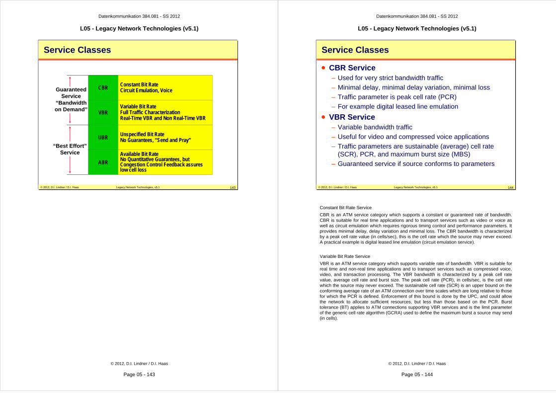
Datenkommunikation 384.081 - SS 2012
L05 - Legacy Network Technologies (v5.1)
© 2012, D.I. Lindner / D.I. Haas
Page 05 - 143
© 2012, D.I. Lindner / D.I. Haas Legacy Network Technologies, v5.1 143
Service Classes
GuaranteedService
“Bandwidthon Demand”
“Best Effort”Service
CBR Constant Bit RateCircuit Emulation, Voice
VBRVariable Bit RateFull Traffic CharacterizationReal-Time VBR and Non Real-Time VBR
UBR Unspecified Bit RateNo Guarantees, “Send and Pray”
ABR
Available Bit RateNo Quantitative Guarantees, butCongestion Control Feedback assures low cell loss
Datenkommunikation 384.081 - SS 2012
L05 - Legacy Network Technologies (v5.1)
© 2012, D.I. Lindner / D.I. Haas
Page 05 - 144
© 2012, D.I. Lindner / D.I. Haas Legacy Network Technologies, v5.1 144
Service Classes
• CBR Service– Used for very strict bandwidth traffic
– Minimal delay, minimal delay variation, minimal loss
– Traffic parameter is peak cell rate (PCR)
– For example digital leased line emulation
• VBR Service– Variable bandwidth traffic
– Useful for video and compressed voice applications
– Traffic parameters are sustainable (average) cell rate (SCR), PCR, and maximum burst size (MBS)
– Guaranteed service if source conforms to parameters
Constant Bit Rate Service
CBR is an ATM service category which supports a constant or guaranteed rate of bandwidth. CBR is suitable for real time applications and to transport services such as video or voice as well as circuit emulation which requires rigorous timing control and performance parameters. It provides minimal delay, delay variation and minimal loss. The CBR bandwidth is characterized by a peak cell rate value (in cells/sec), this is the cell rate which the source may never exceed. A practical example is digital leased line emulation (circuit emulation service).
Variable Bit Rate Service
VBR is an ATM service category which supports variable rate of bandwidth. VBR is suitable for real time and non-real time applications and to transport services such as compressed voice, video, and transaction processing. The VBR bandwidth is characterized by a peak cell rate value, average cell rate and burst size. The peak cell rate (PCR), in cells/sec, is the cell rate which the source may never exceed. The sustainable cell rate (SCR) is an upper bound on the conforming average rate of an ATM connection over time scales which are long relative to those for which the PCR is defined. Enforcement of this bound is done by the UPC, and could allow the network to allocate sufficient resources, but less than those based on the PCR. Burst tolerance (BT) applies to ATM connections supporting VBR services and is the limit parameter of the generic cell rate algorithm (GCRA) used to define the maximum burst a source may send (in cells).

Datenkommunikation 384.081 - SS 2012
L05 - Legacy Network Technologies (v5.1)
© 2012, D.I. Lindner / D.I. Haas
Page 05 - 145
© 2012, D.I. Lindner / D.I. Haas Legacy Network Technologies, v5.1 145
Service Classes
• ABR Service– Useful for computer applications
– Variable bandwidth traffic
– Traffic parameter is minimum cell rate (MCR)
– Includes feedback control
• UBR Service– “Best effort” service
• No real guarantees
– Useful for computer applications
– Variable bandwidth traffic
– No traffic parameters
Available Bit Rate Service
ABR is an ATM layer service category for which the limiting ATM layer transfer characteristics provided by the network may change subsequent to connection establishment. An ABR flow control mechanism is specified which supports several types of feedback to control the source rate in response to changing ATM layer transfer characteristics. ATM end stations that adapts its traffic in accordance with the feedback will experience a low cell loss ratio and obtain a fair share of the available bandwidth according to a network specific allocation policy
Cell delay variation is not controlled in this service, although admitted cells are not delayed unnecessarily. Minimum cell rate (MCR) is an ABR service traffic descriptor, in cells/sec, that is the rate at which the source is always allowed to send. Allowed cell rate (ACR) is an ABR service parameter specifying the current rate, in cells/sec, at which a source is allowed to send.
Maximum cell rate (MaxCR) is required for ABR and UBR (optional for CBR, rt-VBR, and nrt-VBR). MaxCR specifies the maximum available capacity, although the full capacity may not be available for reservation.
Unspecified Bit Rate
UBR is an ATM service category which does not specify traffic related service guarantees. UBR does not include the notion of a per-connection negotiated bandwidth. No numerical commitments are made with respect to the cell loss ratio experienced by the connection, or as to the cell transfer delay experienced by cells on the connection.
Datenkommunikation 384.081 - SS 2012
L05 - Legacy Network Technologies (v5.1)
© 2012, D.I. Lindner / D.I. Haas
Page 05 - 146
© 2012, D.I. Lindner / D.I. Haas Legacy Network Technologies, v5.1 146
Traffic Contract
Traffic Class QoS ParametersTraffic Parameters
Constant Bit Rate (CBR)
Variable Bit RateReal Time (VBR RT)
Variable Bit RateNon Real Time (VBR NRT)
Available Bit Rate (ABR)
Unspecified Bit Rate (UBR)
Peak Cell Rate (PCR) +Cell Delay VariationTolerance (CDVT)
Sustainable Cell Rate(SCR) + Maximum BurstSize (MBS)
Minimum Cell Rate (MCR)
max. Cell TransferDelay (CTD)
Peak-to-Peak CellDelay Variation (ptp CDV)
Cell Loss Ratio (CLR)
Traffic Contract

Datenkommunikation 384.081 - SS 2012
L05 - Legacy Network Technologies (v5.1)
© 2012, D.I. Lindner / D.I. Haas
Page 05 - 147
© 2012, D.I. Lindner / D.I. Haas Legacy Network Technologies, v5.1 147
Traffic Contract per Service Class
• Specified for each service class
CLRCTDCDVMBS
====
Cell Loss RatioCell Transfer DelayCell Delay VariationMaximum Burst Size
PCRCDVTSCRMCR
====
Peak Cell RateCDV ToleranceSustainable CRMinimum CR
CLR Specified Optional Unspecified
max CTD & ptp CDV Specified Unspecified Unspecified
ATTRIBUTE CBR rt-VBR nrt-VBR ABR UBR
PCR & CDVT Specified Specified
SCR, MBS, CDVT Specifiedn/a n/a
MCR n/a Specified n/a
Datenkommunikation 384.081 - SS 2012
L05 - Legacy Network Technologies (v5.1)
© 2012, D.I. Lindner / D.I. Haas
Page 05 - 148
© 2012, D.I. Lindner / D.I. Haas Legacy Network Technologies, v5.1 148
ATM as an Intelligent Bandwidth Management System
UBR burst
AvailableTrunk BW
(e.g. 622Mb/s)
Σ PCR (CBR)
Σ SCR (VBR)
Σ PCR (VBR)
ABR burst
Σ MCR (ABR)
VBR average
VBR burst
CBR constant
+
+
+
ABR average