and( f, f ) = f and( f, t ) = f and( t, f ) = f and(...
TRANSCRIPT

AND( F, F ) = FAND( F, T ) = FAND( T, F ) = FAND( T, T ) = T

Any n-ary function can be built as an OR of minterms.
Minterms are ANDs of variables or their negations.


Q. How much is the time delay for the 4X1 MUX? Assume only basic, 2-input gates are used (AND, OR, NOT). Assume each basic, 2-input gate has a delay of 1 unit from the time its input changes until its output changes correspondingly.
Q. How much is the time delay for a (1 M)X1 MUX? 1M is 2^20.


The above Full Adder (FA) includes two 1-bit, 2X1 MUXes.
Q. What are the min-term functions for one-variable Boolean functions?
Q. Build a 1X2 DEC.
Q. Show a logic design for a 1-bit, 2X1 MUX. Use the organization shown above for the 1-bit, 4X1 MUX. That is, use a DEC to gate input signals to an OR.
Q. How would we build a 3-bit, 2X1 MUX? Show a design using 1-bit, 2X1 MUXes.

module MIPSALU (ALUctl, A, B, ALUOut, Zero);
input [3:0] ALUctl;input [31:0] A,B;
output reg [31:0] ALUOut;output Zero;
assign Zero = (ALUOut==0); //-- Zero is true if ALUOut is 0
always @(ALUctl, A, B) begin //-- reevaluate if these change
case (ALUctl) 0: ALUOut <= A & B; 1: ALUOut <= A | B; 2: ALUOut <= A + B; 6: ALUOut <= A - B; 7: ALUOut <= A < B ? 1 : 0; 12: ALUOut <= ~(A | B); // result is nor default: ALUOut <= 0; endcase
end
endmodule

Algorithms and Computers
We would like to have: -- A simple concept of computation/computing/computersWhy?--- 1. When we build one, we can tell what we want: can it do what it is supposed to do?--- 2. When we see one, we can recognize it (eg. is a QM machine a computer?)--- 3. When we look at a complex system, we can identify its fundamental structure: abstraction.--- 4. We can define what we mean by an algorithm (ie., TM that always halts).
BIG IDEA: Define computation (automatic procedure) Church-Turing Thesis:
Any computation can be done by some Turing Machine (TM).
(Efficiently?)
Can't prove, but works so far.
Operation
1. Read one symbol2. Depending on state and symbol, --- write one symbol --- move R/W head one cell L. or R. --- change state3. Repeat, or if current state is a "halting state", stop operating.

0 / 0 / L
1 / 1 / L
1 / 1 / L 0 / 1 / L
0 / 0 / L
If ( current state == E ) AND ( current symbol == 0 )then ( write symbol == 0 ) ( move R/W head L. ) ( new state == Halt )
On this specific input?
On any general input?
Alternate representation of FSM:
(start state = E)(state, input) (output, move, next state)------------------ -------------------------------------(E, 1) (1, L, O)(E, 0) (0, L, Halt)(O, 1) (1, L, E)(O, 0) (1, R, Halt)
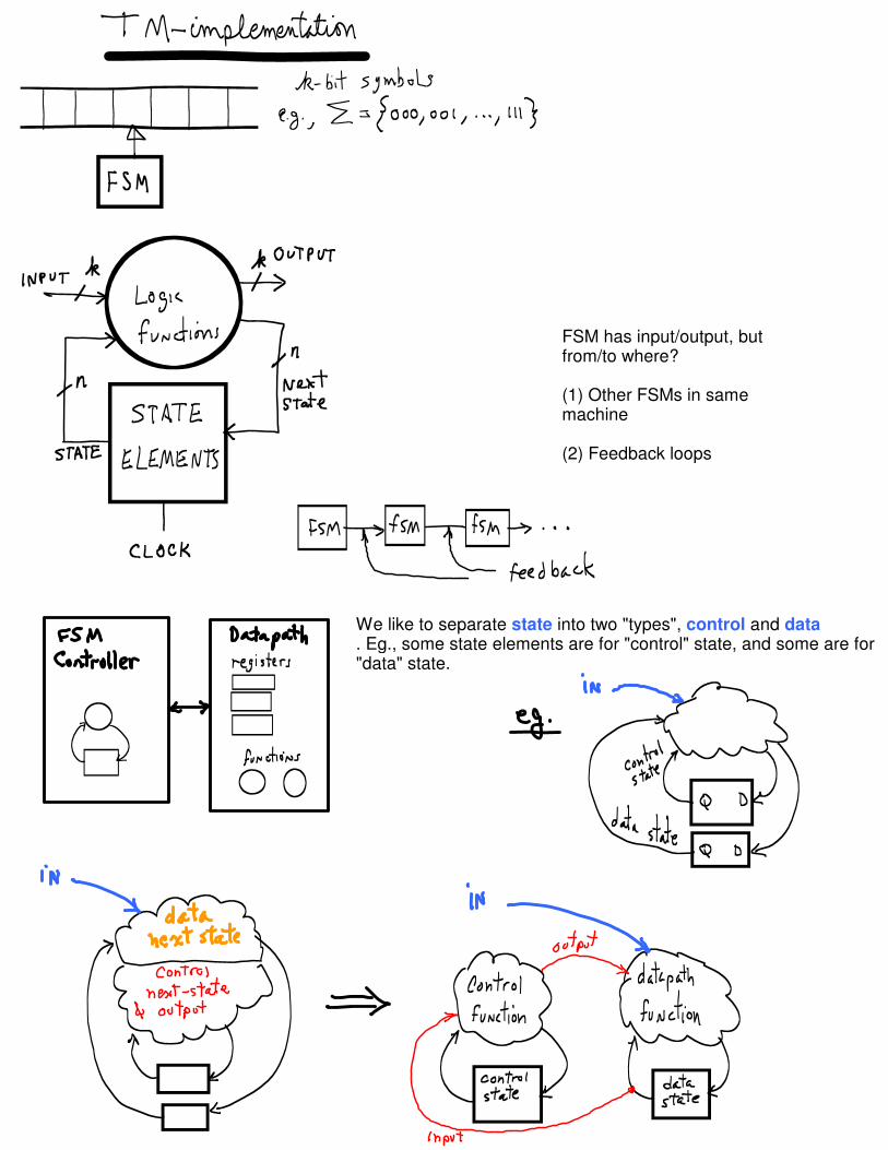
FSM has input/output, but from/to where?
(1) Other FSMs in same machine
(2) Feedback loops
We like to separate state into two "types", control and data. Eg., some state elements are for "control" state, and some are for "data" state.

latch
latch SR latch
We need to remember our "state".
--- Stay in one state: use feedback.--- State is output Q.--- How do we change state?
When A=0, NAND=1.When A=1,NAND=(-B).
Force Q=1.
Stable.
Force Q=0.
Stable.
Use a basic latch to build an SR-latch:
invert S, R inputs.
S = R = 0 stable
S=1, R=0 Q=1
S=0, R=1 Q=0
S = R = 0 stable
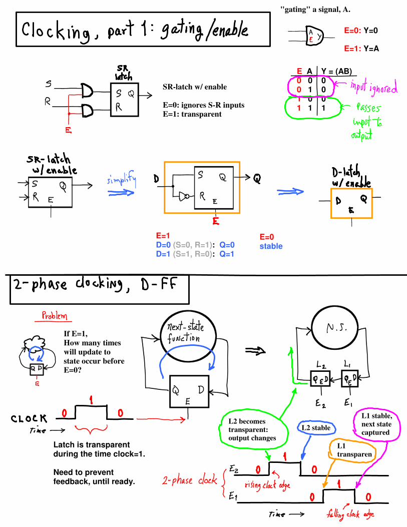
"gating" a signal, A.
E=0: Y=0
E=1: Y=A
E A Y = (AB)0 0 00 1 01 0 01 1 1
SR-latch w/ enable
E=0: ignores S-R inputs
E=1: transparent
E=1D=0 (S=0, R=1): Q=0D=1 (S=1, R=0): Q=1
E=0stable
If E=1,
How many times
will update to
state occur before
E=0?
Latch is transparent during the time clock=1.
Need to prevent feedback, until ready.
L2 becomes
transparent:
output changes
L2 stable
L1
transparen
L1 stable,
next state
captured

We often want to control whether or not the FF will be written into when the clock pulse arrives: add an "enable" input. When enable is 0, the current state is written back into the FF. Otherwise, D is written.
2-Phase Clocking
Separate signals for each latch's enable in FlipFlop. On breadboard we connect PHASE-1 to one data switch, PHASE-2 to another.
If there is no feedback path from Q to D, we do not need a flip-flop, we can use a write-enable latch instead. Datapaths sometimes can use latches.
Positive edge triggeredD Flip Flop

FSM in ROM ( n-bit state, i-bit input, k-bit FSM output )
(STATE, INPUT) is ROM address n bits + i bits ===> 2^(n+i) ROM locations
(NEXT-STATE, FSM-OUTPUT) is ROM output n bits + k bits ====> (n+k) bits per location
===> 2^(n+i) location by (n+k)-bit word ROM
ANY FSM (Mealy or Moore) can be built as a ROM
NOTE: A Moore machine's output depends only on state ===> use n-bit addresses, one ROM location per state.
BUT, next-state depends on current-state+input. Encode part of next-state function in ROM word as NS-CODE, and use external logic to calculate next-state function: next-state = f( INPUT, NS-CODE ). This is what is done in the LC3's micro-coded controller.
Every possible FSM can be built as a ROM.
ROM is very large since there is a word for every possible {state, input} combination.
at clock tick:
-- { current state, current input } captured-- output changes to match captured state/input
-- Every state row has same output ===> Moore Machine
-- Rows for state S have differing outputs ===> Mealy Machine.

We can enumerate all ROMs (and consequently all TMs/digital-computers):
Concatenate ROM content from all words:
address content 00 00 01 11 10 11 11 00
==> 01111000
List all n = i = k = 1 machines:FSM-0, FSM-1, ..., FSM-256
List all n = i = k = 2 machines:FSM-257, FSM-258, ...
and so on.
ADDRESS[1:0]
WORD[1:0]
WORD[0]WORD[1]
ADDRESS[1]
ADDRESS[0]

Collision transfers energy to atoms of material, e.g., wire.
Atom motion = Heat.
~All collision energy radiates as heat.
High Current ==> Many e- MovingHigh Voltage ==> Large E FieldLarge E ==> Fast AccelerationHigh Voltage + High Current ==> Lots of Heat
E, electrical field ~ gravity
E X distance = Voltage

Basic Electricity, The Water Analogy
Conductors
Conduction is the movement of electrons (e-), also known as current, i. (Conduction can also be by positively charged particles.) Any material conducts, if we pull hard enough on the electrons. Charged things, such as e-, move when an electric field (E) is present. In solid materials, the nucleus of an atom contains positively charged protons (p+). Protons and e- attract each other, which gives E, like gravity. In solid material the p+ are fixed in place, but the e- can move. We can think of the solid material as a pipe packed with something; e.g., sand, and the e- as water molecules. Resistance (R) is how tightly packed the material in the pipe is: if it is tighly packed (the material is very fine material such as clay), water molecules have a hard time making it through; if it is loosely packed (large gravel), water drains through easily. The water pressure (V) and R together determine i.
Parallel circuitSuppose we have two identical pipes side by side, and they both have resistance, R, and each has current, i. The current through both is twice the current through one, 2i.
Series circuitIf we connect them end to end instead, we might expect the total resistance to be R+R, and the current to be (1/2) i .
Ohm's Law devicesDifferent materials and devices have different relationships between i, R, and V.If the relationship can be expressed as,
i R = V
then we call the device an Ohm's Law device. Of course, this is only an approximate model. If R is very big, the device is a non-conducting insulator. A big pressure V only gives a little flow. If R is very small, the device is a conductor. A very small V gives a large flow.

It takes work to get water pressure. Suppose we have a water tower. We pull the water up. Pulling the weight w up the tower's height h is the work we do, w X h.
We can get that same amount of energy back from the water in the tank. We can drop a bucket of water and use the pull to do work of some sort. That energy is used up in our packed pipe as the water falls through the pipe: it heats the packing as the water collides with the packing. The heat escapes by radiating away.
The downward force on the water is caused by the gravity field E acting on the water's mass: the weight of the water is E X mass. On the moon, the same mass of water weighs less because the moon's gravity field pulls less than earth's. You can jump high easily on the moon, for instance. Smaller E would mean it takes less energy to move the water: less pressure in the pipe, and less flow, and less heat.
Our model of an electrical voltage source is a tower and very large pipe without packing. It supplies water that flows through our packed pipe, and an energetic process pumps water back up. The pressure at the pump inlet is V- and the pressure at the tank end is V+. The pressure difference V drives water through the packed pipe.
Voltage Source = Pump + Tank + Big Pipe
Device/Circuit = Packed Pipe
The energy lost in the packed pipe by the water that flows through it is the same it took to pump the water into the tank:
energy = weight X h weight = mass X g (g is gravitational acceleration) mass = volume X density (let density = 1) volume = Area X h
energy = (Area X h X 1) X g X h
Here, we are assuming the volume of water that flowed is equal to the volume of the big pipe whose cross sectional area is Area. Because the big pipe is h tall, its volume is Area X h. Suppose we want to see how much energy an amount of water of mass m loses. We first find the energy lost per unit mass by dividing the above by the mass (Area X h X 1):
energy-per-unit-mass = g X h
The energy from mass m is then:
energy-m = m X g X h
Define V (short for voltage-across-the-device) as (g X h):
V = (g X h)
The energy for mass m is then,
energy-m = m X V

A packed pipe with water flowing through it has more pressure on the inlet side than the outlet side. (If it were the other way around, the flow would go backward.) The pressure drops along the pipe. At the inlet side, the pressure is just the total weight of the water in the big pipe pressing down divided by its area:
pressure-h = (Area X h X 1) X g / Area
= g X h
= V
So, the voltage V is the same as the water pressure supplied by the source. Exit pressure is zero because the pump is pulling the water from that end of the pipe.
Suppose k units of water flow per second. The power loss in the device is,
Power = energy-per-unit-mass X (k/sec)
= V X (k/sec)
Current is i and is equal to (k/sec):
Power = V X i
Electrons and water molecules are equivalent. They just differ in their respective fields (E and g) and the properties those fields affect (charge and mass). Power loss is heat (mostly). Note that we have used E and g interchangeably, and applied electrical terminology to water.
Suppose our packed pipes can be modeled by Ohm's Law. Power loss is then proportional to the square of V. It can also be expressed as proportional to the square of i. (Both are shown at right.)
Note for unchanging V, that as resistance R goes to 0, the power loss goes to infinity. This is a short circuit. Before power loss actually goes to infinity, the heat will melt or vaporize the device. Of course, as R goes to infinity, nothing will flow, and no power is lost.

Voltage Divider
At right are two devices connected in series: Between them is a section of empty pipe whose resistance is relatively close to zero (wire).
The pressure (voltage) across device1 is the source voltage Vs minus the "output" voltage Vout. The current exiting device2 has pressure Vg = 0. So, the voltage across device2 is Vout.
The "output" of this system Vout depends on the two resistances, R1 and R2. The current i is the same through both resistors.
Suppose R2 is nearly 0 (a resistance-less wire). The total voltage difference over both resistors is (Vs - Vg) = Vs. The output voltage is the voltage difference across R2. Because R2 is about 0 (i.e., it has no packing, water passes through easily) 0 volts is almost all that is needed to move water through it. That is to say, no water pressure can build up on the inlet side of R2 because when it starts to build up, water flows through before any pressure can build up. The current i is completely determined by R1.
In the other extreme, suppose R2 is nearly infinite (an open circuit or switch). No matter how much pressure there is, almost no current flows.
i = (Vs - Vg) / (R1+R2) = Vs / (R1+R2) ~ 0
Pressure will build up as flow exits R1 and gets stopped by R2. Water would flow through R2 if the pressure at one end were different from the pressure at the other end. But, no current flows. So, the pressure at both ends must be the same. That is, Vout is the same as Vs. (Vs - Vout) = i R1 ~ 0 R1 = 0 Vs ~ Vout
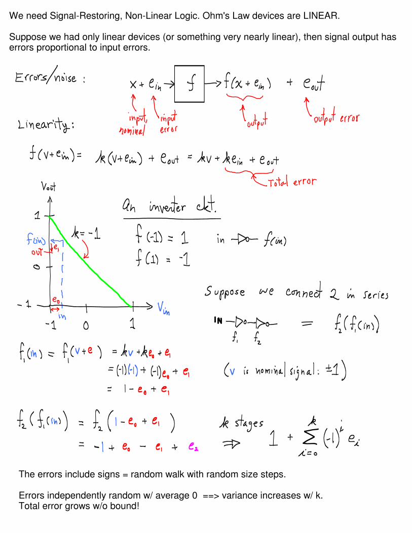
We need Signal-Restoring, Non-Linear Logic. Ohm's Law devices are LINEAR.
Suppose we had only linear devices (or something very nearly linear), then signal output has errors proportional to input errors.
The errors include signs = random walk with random size steps.
Errors independently random w/ average 0 ==> variance increases w/ k.Total error grows w/o bound!

Take random step (either in the -1 or +1 direction). How far from 0 can you expect to be after k steps? About k^1/2 away.With probability 0 you will be at 0, and error gets unboundedly large.
We must Reduce error at each stage ==> exponentially decreasing effect in later stages.
If g is large enough (flat areas of curve are flat enough),
and
if output error size is not too big,
Then
output after k stages never hits FORBIDDEN ZONE.
So, if we plan to have a circuit with long device chains, we must have non-linear devices w/ suitable response curves.
Do we plan to have long chains? YES:
(1) feedback in system,(2) chained data operations: D1 ==> D2 ==> D3 ==> D4 ...(3) 1 Billion devices per cpu

--- Non-linear response
--- Any voltage in allowed range will yield "clean" output.
--- Easy to prevent forbidden input voltage.
Voltage Controlled Switch

Phosphorous impurity:
e- leaves easily, becomes "hot"
conduction-band e- .
Boron impurity:"cold" valence-band e- arrives, leaves behind +valence
"hole" which moves.
Holes and e- move in opposite directions, but current
direction is same.
Easy e- flow from n-type to p-type, but reverse flow
hard: "cold" valence-band e- need too much energy to become conduction band e-.
n-type MOSFET (n-transistor)
CONDUCTING ( Vgate = +V, R-drain-to-source ~= 0):
+V on gate drives holes away from P-type channel.
Conduction-band e- move from source N-type well.+V on drain pulls conduction-band e- off.
+I current flows left-to-right.
NOT-CONDUCTING ( Vgate = 0, R-drain-source = BIG)
Vgate = 0, holes populate channel.
Source N-well e- drop into valence band in channel.
+V at drain cannot pull valence-band e- from P-type to N-type.
holes moving ==>
e- moving <==
Just what we want: nice non-linear switch.

P-type (n-channel) transistor
Vgate = 0:
Vgate = -Vdd wrt to base,pushes e- away from channel, leaves
excess holes, current flows.
R = 0, conducting.
Vgate = Vdd:
Vgate = 0 wrt to base
channel is neutralonly random thermal e- available for
current flow.
R = infinity, not conducting


Lithography

LC3 Intro/Review

.orig x3000
ld r1, sixld r2, numberand r3,r3,#0
again add r3,r3,r2add r1,r1,#-1brp again
halt
number .blkw 1six .fill x0006msg .string "abc"
.end
00110000000000000010001000000111001001000000010101010110111000000001011011000010000100100110000100000011111111011111000000100101000000000000000000000000000001100000000001100001000000000110001000000000011000110000000000000000
Assembler (lc3as) Directives (to control the assembly process):.orig: puts a load address into the .obj load-object file's header..end: tells assembler, this is the end of source code..blkw: tells assembler, create n blank words (all zeroes)..fill: tells assembler, put these bits into a word. .string: convert text to .FILL w/ one ascii code per word, NUL terminated.
The assembler produces machine code words:--- ONE PER LINE expressing an LC3 instruction--- ONE PER LINE where there is a .fill directive--- n PER LINE where there is a .blkw directiveThe assembler also calculates offsets for us using symbols. Symbols stand for memory addresses (starting for the .orig address). Offsets are calculated by subtraction. Symbols refer to the next instruction's location.

.orig x0200main:
ADD R1, R2, R3ADD R4, R5, var
foo: .FILL x1234var: .FILL x012F
.end
00000010000000000001001001000011000110010110000100010010001101000000000100101111
0200: 00010010010000110201: 00011001011000010202: 00010010001101000203: 0000000100101111

main: LD R3, var ...var: .FILL x023F
symbol value"main" x0200"var" x0208
0200: 0010 011 000000111 ... ...0208: 0000 0010 0011 1111

main: LD R2, tablePTR LDR R1, R2, #2 ...tablePTR: .FILL table ...table: .FILL x0000 .FILL x0001 .FILL x0002
"main" x0200"tablePTR" x02F0"table" xFF00

Source Codemain: LEA R3, array ...array: .BLKW 100
Symbol Table"main" x0200"array" x0210
Memory0200: 1110 011 000001111... ...0210: ????0211: ????... ...
Source Codemain: ADD R0, R0, 1 BRp main
Symbol Table"main" x0200
Memory0200: 0001 000 000 0 000010201: 0000 001 111111110
9-bit offset:PC +/- 256

Source Code:main: LEA R7, next BRnzp foonext: ADD R0, R1, #11
...foo: ADD R0, R1, #10 JMP R7
...JMP R7
TRAP x05
Moore FSM--- Output not a function of input--- Output determined by state only
MealyFSM


