and the propeller education kit
TRANSCRIPT
Propeller MicrocontrollerAnd the Propeller Education Kit

Why learn microcontrollers?
• Digital alarm clock• Microwave oven• Alarm system• Cell phone• Automobile
Because they are the “onboard computers” built into devices that interact with their circuits. Examples include
• Computer keyboard• Heart monitor• Factory equipment
subsystems• Etc…

The Propeller Microcontroller?
• 8 parallel 32-bit processors (cogs)• 32 I/O pins• 32 KB of shared (main) RAM• Each cog has 2 KB of RAM• Clock speeds up to 80 MHz• DIP, QFP and QFN packages
From PE Kit Labs, page 7

Why the Propeller Microcontroller?
Conventional approach to multitasking with a single core microcontroller.
Single processor alternates between tasks
…
…
…
…
1 9 11 15
2 3 4 5 6 7 8 10 12
…
…

Why the Propeller Microcontroller?Multicore Propeller approach.
Propeller cog
…
…
Another Propeller cog
Read Propeller Education Kit Labs: Fundamentals, chapter 1 to find out more.
…
…
1 2 3 4 5
1 2 3 4 5 6 7 8 9 10 11
…
…

Propeller Education Kit (PE kit)
Propeller Education Kit – 40 Pin DIP
40-Pin DIP Version
~, . l
. --0' ,
• 1'! -.. \
" ,
• .. "
-
"'" V

PE Kit Labs: Fundamentals Book• For those new to the Propeller• Guided tutorial• Accompanies both versions of
the PE Kit• Prerequisites
– Familiarity with electricity & electronics
– Familiarity with a high level programming language (C++, Java, BASIC, Pascal, Python, etc.)
– OR complete What’s a Microcontroller

Programming Languages
Propeller Tool Software Help• Get Started: Propeller Education Kit Labs: Fundamentals• Reference: Propeller Manual• Objects: Propeller Object Exchange – obex.parallax.com• Propeller Forums: forums.parallax.com -> Propeller• Coding Aid: Propeller Chip Quick Reference
• Native high level Spin language and low level Propeller Assembly Language have the best documentation support.
• Many other languages are available, including C, BASIC, Forth, Java, and more…

Propeller Education Kit Labs: Fundamentals
Chapter 1 Propeller Microcontroller & PE Kit
Labs Overview

From PE Kit Labs, Ch 1
A Cog Interpreting SpinMain (Hub) Memory
32 Configuration KB
Application
=f------1 M Stack + VAR
Character 32 Set KB f------1 R Log, Antilog, & o Sine Tables M f--,,-----1
Boot Loader Interpreter
(a) Interpreter loaded into cog from Main Memory's ROM through Hub
Main (Hub) Memory Fetchl
Configuration
R Application A 1\ M
Stack + VAR
(g) Character Set
R 0 Log, Antilog, &
M Sine Tables
Boot Loader Interpreter
(b) Cog fetches token from Main Memory's RAM
Main (Hub) Memory
Configuration
~ R Application A M
Stack + VAR
Character Set
R 0 Log, Antilog . &
M Sine Tables
Boot Loader tiD
Interpreter
(c) Cog executes token. Examples include RAM, 110 or config read/write, or ROM read

From PE Kit Labs, Ch 1
A Cog Executing ASM
Main (Hub) Memory
Configuration
R Application A M
Stack + VAR
Character Set
R 0 log. Antilog . &
M Sine Tables
Boot loader Interpreter
> .. . 7 to 22
clock cycles, 16 cycles
when synchronized
ASM
4 clock ~
COG

Ch 1
Cogs CommunicatingMain (Hub) Memory
Configuration
R Appl ication A 1--___ --1 M
R
Stack + VAR
Character Set
o Log, Antilog, & M Sine Tables
Boot Loader Interpreter

Ch 1
Cogs Launching Cogs
Ch 1
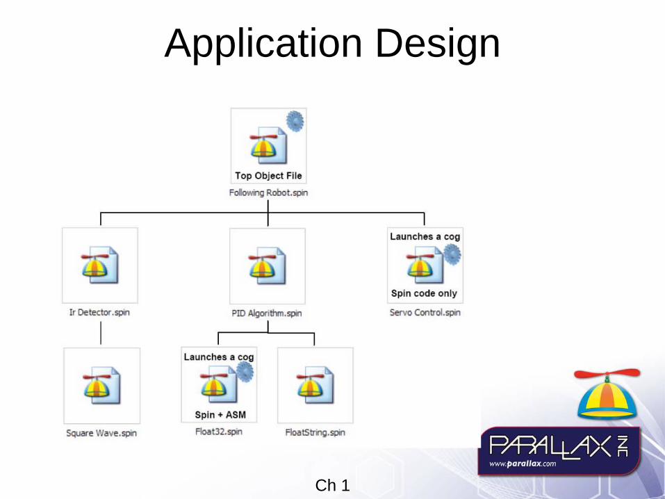
Application Design
Squar~ Wave.spin
-r-;. Top Object File
_ Robot."",
I
PID AIoorittvn. spin
I
Sp in + ASM
Roat32. spin
Launches a cog
Spin code only
Servo Control,spin

Ch 1
Program Loading & Storage
Propeller Code
=====:::::J Serial over USB
(!) --. _.
Propeller Code
Copy to t I Load from EEPROM EEPROM t after Reset
======, Serial over USB

Propeller Education Kit Labs: Fundamentals
Chapter 2 Software, Documentation, and
Resources

From PE Kit Labs, page 17
Follow these Instructions!
From PE Kit Labs, page 17
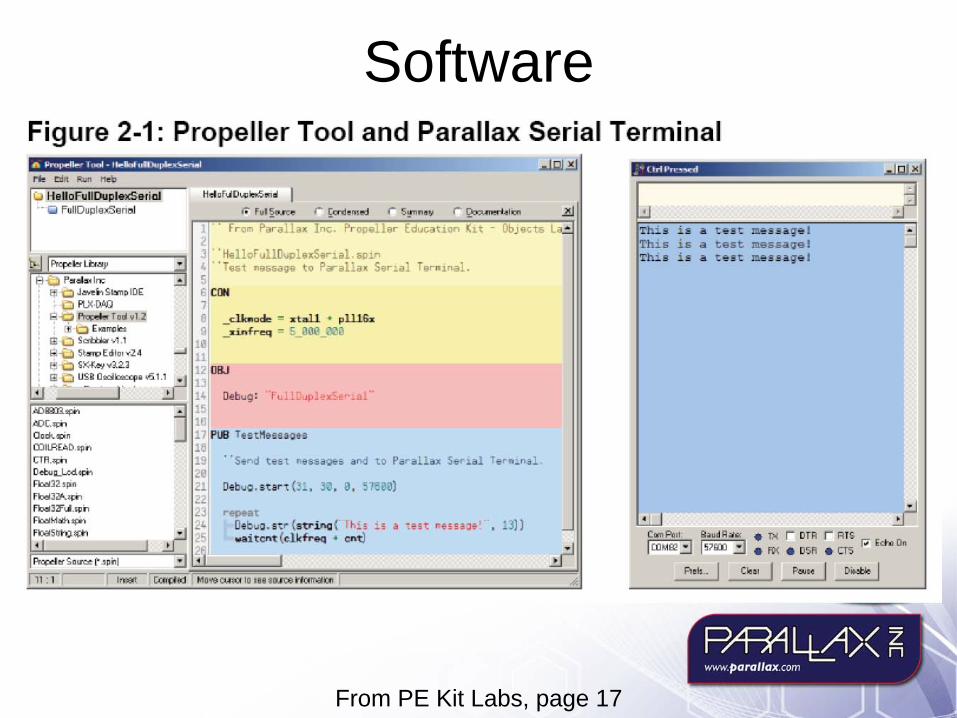
SoftwareFigure 2-1 Propeller Tool and Parallax Serial Terminal III ~ll.- I ..... _, ... W"Il ... ~ .......... j
CJ HellaFuliDuplexSariai -' Iiij FQllDupleKSQnClJ
0 "
"' ,
H ... roJ[ h ... ~.., ..
Co r r r
·H911orul1~laKSt~lal.tiPln 'Tast n8ssaQ8 to Paral:a~ 5arlal TarRlnal .
_cl.koooR " " tall • pillS. _ ainfr eq " 5_908_008
"-, DtbuO . i tr {5tr~{ ... itcr>'t (clkfreq •
" , Thi s i s a t ~5t m~3 s aq& 1
Th~s is a tast m95saga ! This is a t e st ~&s5aq& 1
C ... FI,nl
Icm.ta:!3 e,udA_ • 1X
Imoo:::oJ • ~ Floll .• Clo ..
r DTA
. DSR r RTI>
[';7 ~cr" On . m , ...

From PE Kit Labs, page 18
During Software Installation Make sure to leave the Driver Install checkbox checked!

From PE Kit Labs, page 18
Resources Bookmark ‘em!
Useful Web Sites In addition to www.parallax.comlPropeller. there are a couple of other web sites where you can get answers to questions as well as objects to reduce your development time on Propeller projects .
• Object exchange: http ://obex.parallax.com • Prope ller Chip f011lm: http://f011lms. parallax.com -> Propeller
Tech Support Resources Parallax Inc. offers several avenues for free technical support services:
• Email: [email protected] • Fax: (9 \ 6) 624-8003 • Telephone: Toll free in the U.S: (888) 99-STAMP; or (9 \ 6) 624-8333. Please call between
the hours of 7:00 am and 5:00 pm Pacific time, or leave us a message. • Forums: http://folllllls.parallax.com/follIlI1S/' Here you will find an active fOlllll1 dedicated to
the Prope ller chip, frequented by both Parallax customers and employees.

Propeller Education Kit Labs: Fundamentals
Chapter 3 Setup and Testing

From PE Kit Labs, page 19
PE Platform

From PE Kit Labs, page 27
PE Platform Schematic
Vbat
fi-!l voc
-=-P'.Ishbutloo
~ " e , • "
, • ~ • y ,. , • ~ ,
(B{ • ~
, • "' • "
'" • " 3.~V I SQE. n in " ~ L RES• " " 1 ~
n " n ~~ " " " GND e" " 0 _ • ,,' " •
' " " " e" " " e" " " '" " " CIP-40
3.3V LEO
1000 IJF
GND
... ,,, e~
T .. e. .c;nA
'" en eo
"' 3.3'1 "" 3 c'Y ......
::~ -"~ GND I'SS~
"' m
" ' GND
," '" '" '" en
100 0
Pro~I"r Plug
10'"
24LC25E
• --" e
... =-"--" To PC
3.lV
-GND

From PE Kit Labs, page 28
PE Platform Wiring One of the intermediate steps…

From PE Kit Labs, page 31
PE Platform Wiring Ready to test…
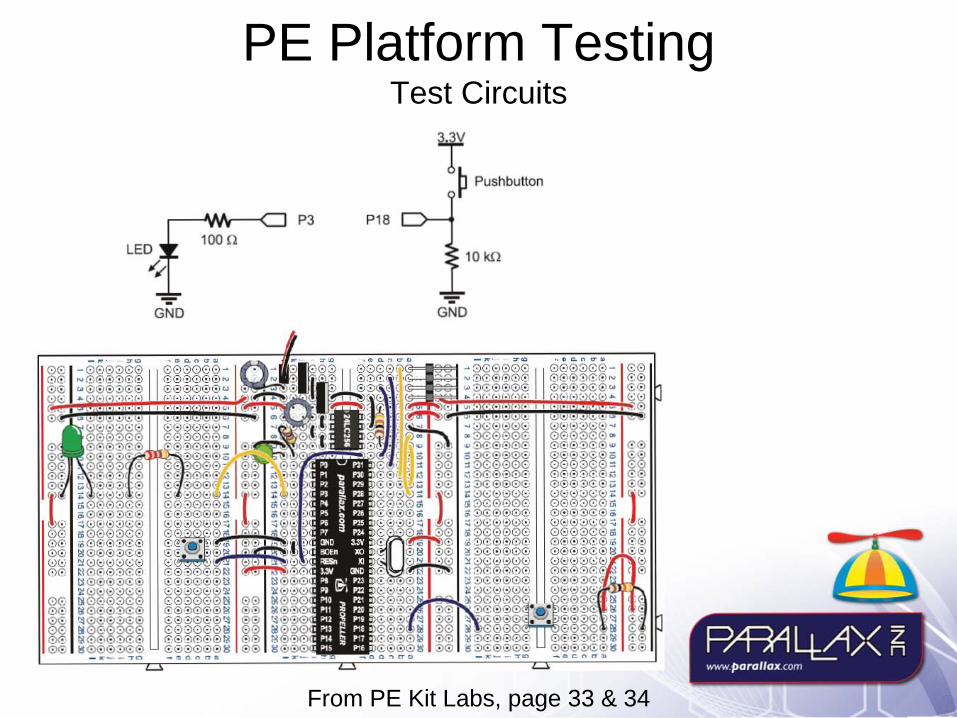
From PE Kit Labs, page 33 & 34
PE Platform Testing Test Circuits
0€ 00 00 OC 00 00
LED
"'''' GND
100 "
1-~ Pushbutton
P3 P18
10 kll
GND
From PE Kit Labs, page 35
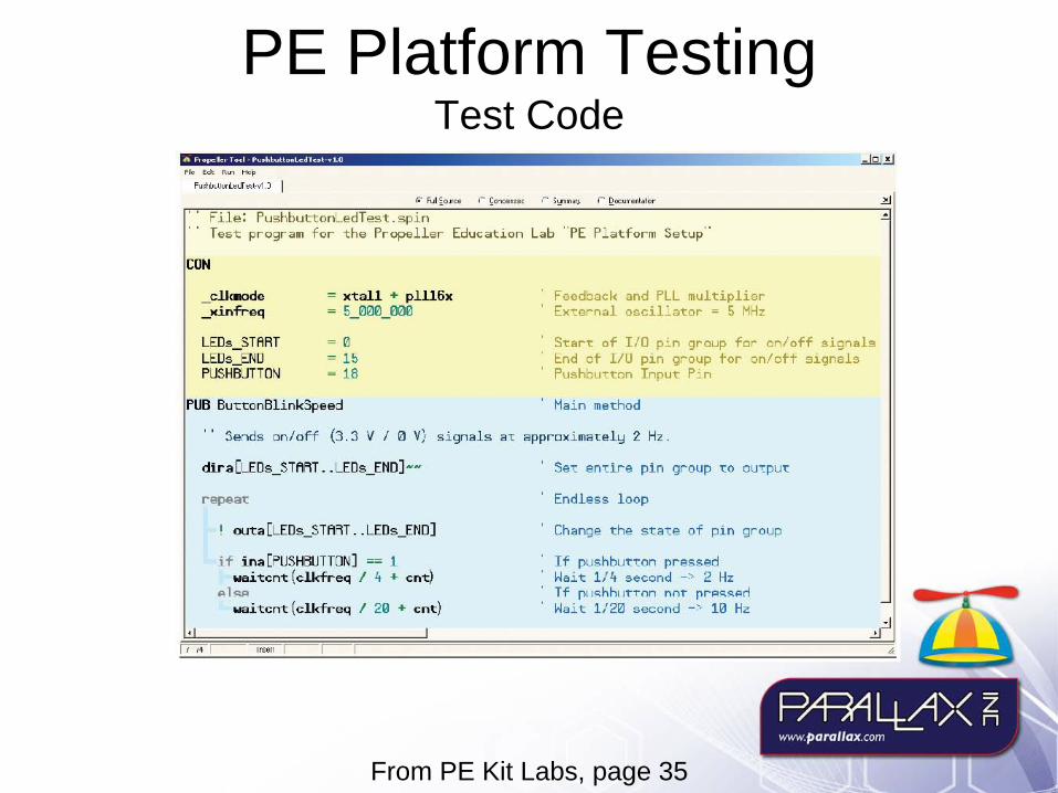
PE Platform Testing Test Code
r k [ de R~ ' '''_
F"I W , ... L..J "h1.)
File: Pu"hbuuonLedT es"t. 5p~n Test program for "the Propeller Edu<;a"tion Lab "PE Pla"tform Se"tup"
CON
LEOs_START LEOs_END PUSHBUTTD~
PUB ButtonBlinkSpeed
xtall + plll6x 5_00~U100
o lb 18
Feedback and PLL mul"tiplier E~cernal oscil:acor = 5 HH~
Scare of I/O p':'n group for an/off signal!;! ~nd at I/U p1n group tor on/ott signals Pushbucton Input P':'n
Hai n method
" Sends on/off (3.3 V / 0 V) si9'a15 ae approxi lllately 2 Hz .
repeat
I outa[LEDs_STA,T .. LEDs_ENO]
if ina[PUSH3UTTON ] == 1 waitcnt (clkfreq / 4 + cnt)
",,1~
waitcnt (clkfreq / 20 + cnt) I., ,
Sec enelre pin group 1:0 OUcpU1:
Endless loop
Change the stace of pin group
If pushbut1:on pressed ~ait 1/4 second - > 2 Hz T f rll~hhl rt"tnn nnt" prp~~prl
~ait 1/20 second -> 10 Hz

Propeller Education Kit Labs: Fundamentals
Chapter 4 I/O and Timing

From PE Kit Labs, page 44
Lab 4: I/O and Timing Circuit for this lab
LEOs 100 U(all )
,(,( P4
P5 3.3V 3.3V
,(,( To To P6 ~ Pushbutton ~ Pushbutton
,(,(
3.3V
To ~ Pushbutton
,(,( P7 P21 P22 P23
,(,( P8 10 k.rl 10 kU 10 k.rl
pg ,(,( - -- -GND GND
--GND
--GND

From PE Kit Labs, page 48
Lab 4: I/O and Timing Emulate a Wire

From PE Kit Labs, page 50
Lab 4: I/O and Timing Indenting code blocks

From PE Kit Labs, page 51
Lab 4: I/O and Timing The WAITCNT Command

From PE Kit Labs, page 52
Lab 4: I/O and Timing Blinking LED
.. File : ConstantBlinkRate .spin
CON
_xinfreq = clkmode =
5 000 000 - -xtal1 + pll16x
PUB LedOnOff
dira[4] : = 1
repeat
outa[4] := 1 waitcnt(clkfreq /2 + cnt) outa[4] := 0 waitcnt(clkfreq / 2 + cnt)

From PE Kit Labs, page 62
Lab 4: I/O and Timing This is important!
"File : TimekeepingBad .spin
CON
VAR
_xinfreq = 5_000_000 clkmode = xtall + plllx
long seconds
PUB BadTimeCount
dira[4J--
repeat waitcnt (clkfreq + cnt ) seconds ++ ! outa[4J
"File : TimekeepingGood .spin
CON
VAR
_xinfreq = 5_000_000 _clkmode = xtall + plllx
long seconds , dT , T
PUB GoodTimeCount
dir a [9 .. 4 J- -
dT : = clkfreq T : = cnt
repeat T += dT wai tcnt (T) seconds ++ outa[9 .. 4J seconds

Propeller Education Kit Labs: Fundamentals
Lab 5 Methods and Cogs

From PE Kit Labs, page 69
Lab 5: Methods & Cogs Calling a Method
.. CallBlink .spin
PUB Main
repeat outa[9] = dira[9] : = 1 repeat until ina[23] outa[9] : = 0 Next
Methodl....---:. Blink ................. Command Call 2: .... ·wai'i:~~t · (~ikf;~~/2+3 + cnt)
PUB Blink I pl.n, rate, reps
p~n · - 4 · -rate · - clkfreq/ 3 · -reps · - 9 · -
Method dira[pin]-- Return outa [pin]-
repeat reps • 2 waitcnt (ratel2 + cnt ) 'outa[pin]
From PE Kit Labs, page 70
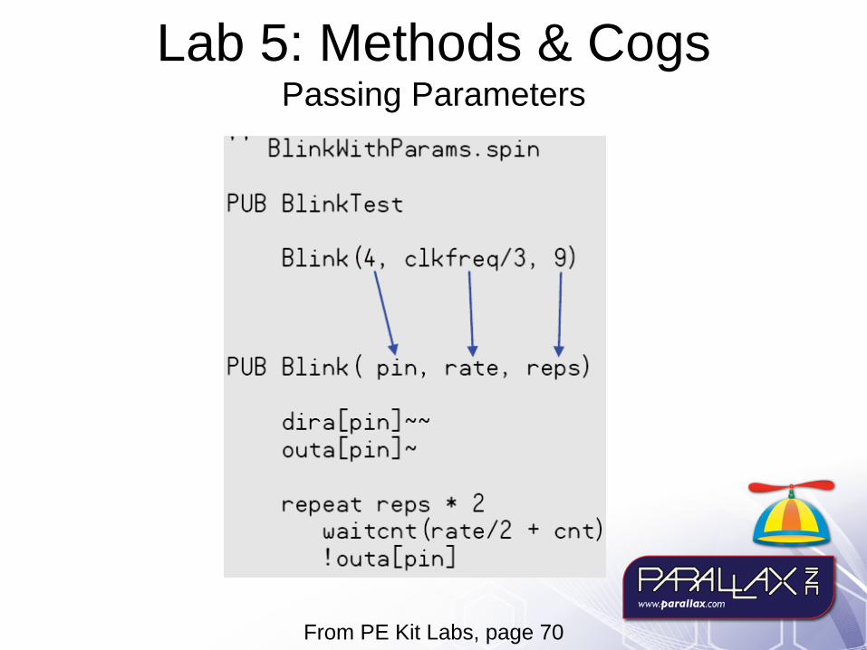
Lab 5: Methods & Cogs Passing Parameters

From PE Kit Labs, page 73
Lab 5: Methods & Cogs Method Return Value
(Step 3) ButtonTi.c method's rcsul t value Is assigned to the Hain
.. ButtonBlink.spln
PUB r'la i n I time
method's tue variable ~eat
t~me : = ButtonTime(23) --__ _ (Step 4) tJ.me Is used In
the Blink method call
(Step 1) ButtonTime method call passes
23 to Button T i.e'S pin parameter
Blink 4, t l me , 10)
j PUB Bl i nk (pin, rate, I'eps)
dira[pin]-~ outa[pin]-
(Step 5) Blink method receives time as the
value to use In Its rate
parameter repeat reps * 2
waitcnt(ratel2 !outa[pw]
+ c nt)
PUB ButtonTime (pin) I t1, t2
re pea t unt i l i na [p i n] t1 : = c n't repeat whi l e l na[p l n] t2 : = c nt result : = t2 - t1
(Step 2) ButtonTime method defines the rcsult: variable and returns this value to the method call
From PE Kit Labs, page
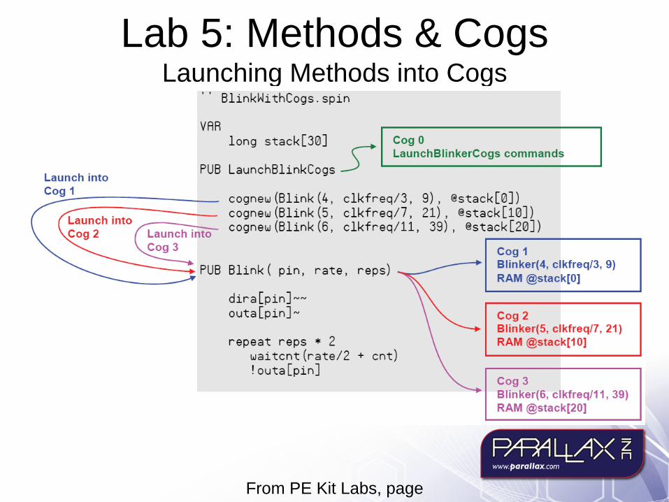
Lab 5: Methods & Cogs Launching Methods into Cogs

From PE Kit Labs, page 72
Lab 5: Methods & Cogs Memory Map and Stack Space

From PE Kit Labs, page 73, 74
Lab 5: Methods & Cogs Calculating Stack Space
• 2 - retum address • 1 - retum result • number of method parameters • lllunber of local variables • workspace for intennediate expression ca lculations
repeat r eps • 2 waitcnt (r ate/2 + cnt )
• 2 - retuI1l address • I - result variable (every method has this built-in, whether or not a retuI1l va lue is specified.
This will be introduced in the next section.) • 3 - pin, f r eq , and reps pannneters • 1 - time local variable • 3 - workspace for calculations.
• 10 - Total

Propeller Education Kit Labs: Fundamentals
Lab 6 Objects

From PE Kit Labs, page 84
Lab 6: Objects Calling methods in another object with “dot notation”

From PE Kit Labs, page 85
Lab 6: Objects Object View Pane (Upper-Left)
" Propeller Tool - DotNotationExample
File Edit RLJl Help
o DotNoialionExa.ple L_ CJ ButlonAndBink
DotNotationExamp!e- I r. FullSoulce r Condensed r Sl.mrMIY
, 'F ile: DatNatatianExa.ple . spin
.. II ~. OOJ ..!!:.I P,opelle,litxa,y ..:.J ~~~--~--------~ E1 -e Palallax Inc
OO-t:::) Javelin Stamp IDE oo-t:l PlOpelel Tool v 1. 0 , IE- SClibblel ,
Stamp Editol v2.2.6 .-oJ ,
i
-
. -e SX-Key .3.2 - USB Oscilloscope V5.0~
FloalM alh spin FloalStling.spin F ullO uplexSeliai.spin
....J
..:J
PbLed "ButtanAndBlink"
PUB Main I ti.e
repeat
time := PbLed.ButtanTi.e(23)
PbLed.Blink(4, time , 20)
I Plopellel Soulce (-.spin) :::J -116 : 1 I I Ins.,' I Compiled I MQIr'e CUSOI 10 see sOUlce infOfmation I
r Oocument~ion

From PE Kit Labs, page 86
Lab 6: Objects Objects that Launch Cogs

From PE Kit Labs, page 91
Lab 6: Objects Documentation View – Schematic & Object Interface

From PE Kit Labs, page 91
Lab 6: Objects Documentation View – Methods

From PE Kit Labs, page 92
Lab 6: Objects Character Map

From PE Kit Labs, page 93
Lab 6: Objects Schematics in Your Documentation Comments

From PE Kit Labs, page 95
Lab 6: Objects Object Arrays
"Top File: MultiCogObjectExample.spin
OBJ
Blinker[6] Button
"Blinker" "Button"
PUB ButtonBlinkTime time. index
repeat
repeat index from 0 to 5 time : = Button.Time(23) Blinker[index].Start(index + 4. time. 1_000_000)
repeat index from 5 to 0 Button. Time (23) Blinker[index].Stop

From PE Kit Labs, page
Lab 6: Objects Displaying Messages with FullDuplexSerial

From PE Kit Labs, page 99
Lab 6: Objects Declaring & Using the FullDuplexSerial Object

From PE Kit Labs, page 101
Lab 6: Objects FullDuplexSerial’s Documentation Comments
n ~o",( .. (ode
Fc.€I..pe,6..... I r F"iouce r ~od r s!:!"mo<)l ... .... ... ... .... ... ... ... .... ... ...
Full-Duplex S~rial Driver v1.l (e) 2006 Parallax , Inc. .... ... ... ... .... ... ... ... ... .... ...
Obj ect "FullOuphxSer id" Interhce :
PUB s ta r t (rxp in, txp i n, node , baudrate) PUB stop PUB r xf l ush PUB rxcheck r,byte PUB rxtineCns) rxbyte PUB r x: r xbyte PUB tx(txbyte) PUB str (str ingptr) PUB dec (value) PUB hex (value, :ligit s) PUB bin (value, :ligits)
Prograll : Variable :
168 Longs 1B Longs
PUB star t (rxpin, t xpin, node , baudrate)
Start serial dr i ver - start s a cog returns false if no cog available
~ ode b i t , invert " Mde bi t 1 invert " ~ode bi t , op~n-drain/eource " ~ ode b i t 3 ig,ore tx echo on "
okay
okay
r s!:!"mo<)l
PU B rxti~ e (ns) rxby t e
Wait hS ~ illiseconds for a byte to be rece ived r eturns - 1 if no byte received, SIl Il . . SFF if byt,
PU B rx rxbyte
Receive byte (hay ...ait for byte) r eturns SIlIl .. SFF
PU B tx (t xbyte)
Send byte (hay wa it f or roo~ in buff er)
PUB stdst ringptr)
Send str ing
PU B dec(value)
Pr i nt a decina1 nunber
PU B hex (va lue , di gits)
Pr in t a hexadeci~al nu ~ber

From PE Kit Labs, page 103, 105, 107, 113
Lab 6: Objects Parallax Serial Terminal Application Examples

Propeller Education Kit Labs: Fundamentals
Lab 7 Counter Modules & Circuit
Applications

Block Diagram
PE Kit Labs Book, page 221
Cog 0 Cog 1 Cog' Cog 3 Cog4 CogS Cag6 Cog 7
• Hob
T Ro..,,,,,, • ., I-SO _I ~~ ~'"
'*"'10X, " " (j) "
@-/ • -" 0-'" CotE".~ .. • (WU'l liO
P6X32A-Q44 P'." IIYlA'WXZZ \ SOfl~ES
~.J..EN'
CSCE,,' :ool!l"'O_ floooioler
»:NODe CLi'.l;Q. ..
~ /
Hub and Cog Interaction
p~~><~ W\VW, paraI/Qx.com

From PE Kit Labs, page 121
Lab 7: Counters Modules… What’s a Counter Module?

Counter Module Modes• POS/NEG detector
– Measure Pulse, RC, Duty cycle
• w/Feedback– ADC
• Edge Detect– Frequency
measurements, count events
• LOGIC– Detect conditions
• NCO– Square waves, clock
signals, PWM, duty Cycle
• PLL– High frequency square
waves and clock signals, video mode
• DUTY– DAC

From PE Kit Labs, page 122
Lab 7: Counter Modules… How do They Work?

From PE Kit Labs, page 122
Lab 7: Counter Modules… Circuit Application: Measure RC Decay

From PE Kit Labs, page 123
Lab 7: Counter Modules… RC Decay Circuit Steps

From PE Kit Labs, page 127
Lab 7: Counter Modules… Doing other Things While Counter Measures RC Decay

From PE Kit Labs, page 124
Lab 7: Counter Modules… Subtitle

From PE Kit Labs, page 125
Lab 7: Counter Modules… Counter Setup Steps for RC Decay

From PE Kit Labs, page
Lab 7: Counter Modules… from TestRcDecay.spin
, Charge RC circuit .
dira [17] : = outa[17] . - 1 waitcnt (clkfreq/ 100_000 + cnt )
Set pin to output-high Wait for circuit to charge
, Start RC decay measurement. It's automatic after t his ...
phsadira [17]-
Clear t he phsa register Pin to input stops charging circuit
, Optional - do other things during the measurement.
Debug. str (S tring (CR, CR, "Working on other tasks", CR) ) repeat 22
Debug . tx (" . ") waitcnt (clkfreq/ 60 + cnt)
Measurement has been ready for a while . Adjust ticks between phsa~ & dira[17]- .
time : = (phsa - 624 ) #> 0
, Display Result
Debug . Str (String (13, " time = " )) Debug.Dec (time) waitcnt (clkfr eq / 2 + cnt )

From PE Kit Labs, page 132
Lab 7: Counter Modules… D/A Conversion
From PE Kit Labs, page 131
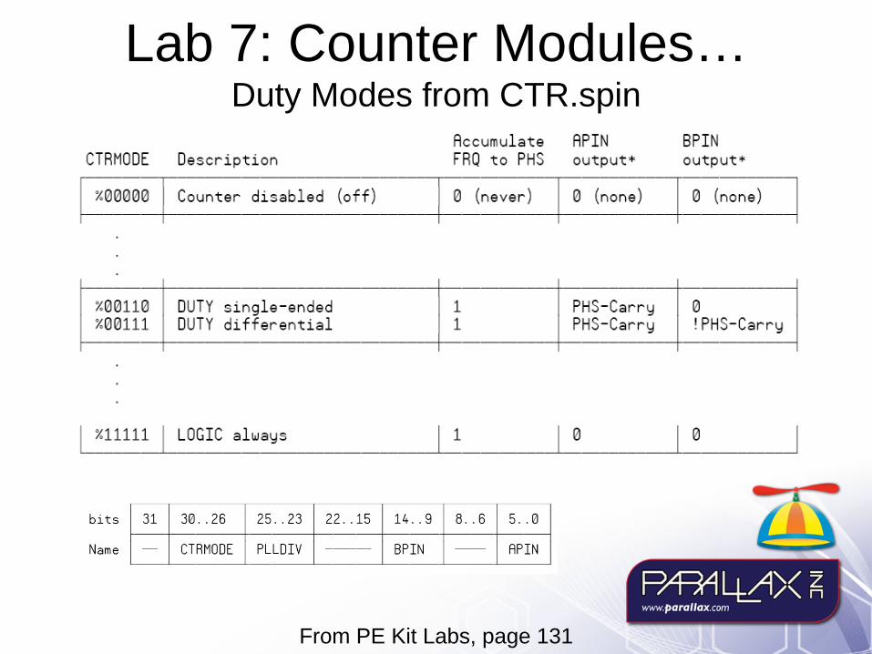
Lab 7: Counter Modules… Duty Modes from CTR.spin

From PE Kit Labs, page 131
Lab 7: Counter Modules… Steps for Setting up a Duty Mode Signal

From PE Kit Labs, page 132
Lab 7: Counter Modules… Duty Mode Example

From PE Kit Labs, page
Lab 7: Counter Modules… Metal Detection
Par ts List
(1) Capac1 tor to pr (2) Jumper Wi res (2) Res 1stors 100 0 (~isc ) res1stors : 220. 470 . 1000 . 20a0, 101<
\ ~--'.
Schematic
R' R2
'" '00
- -GNO GND
'" CO
R' "., "" '00 11
101n (2 .5" W .. Loop)

From PE Kit Labs, page 171
Lab 7: Counter Modules… Notch Filter Resonant Frequency
'.OOe=====~=========+~========+=~====~
10~+---------------------~------------+----------" 38141z 58Hlfz 7mtHz 90HH z
o U(P13) <> U(1"15) Frcqucm;y
1 L
1

From PE Kit Labs, page 172
Lab 7: Counter Modules… Step Response of Notch Filter

From PE Kit Labs, page 173, 174
Lab 7: Counter Modules… Eddie Currents and Reflected Impedance

From PE Kit Labs, page 175 - 176
Lab 7: Counter Modules… Metal Detection Application – Measure Frequency Response
CalibrateMetalDetector.spin