anderson greenwood - mramco · anderson greenwood low pressure poprv catalog series 90 and 9000...
TRANSCRIPT
Anderson Greenwood Low Pressure POPRV CatalogSeries 90 and 9000 Pilot Operated Pressure Relief Valves
Total Flow Control Solutions™ Copyright © 2008 Tyco Flow Control. All rights reserved. ANGMC-0251-US-0810
Flow Control
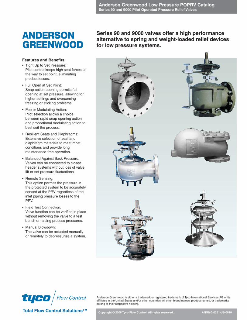
Features and Benefits• Tight Up to Set Pressure:
Pilot control keeps high seat forces allthe way to set point, eliminatingproduct losses.
• Full Open at Set Point:Snap action opening permits fullopening at set pressure, allowing forhigher settings and overcomingfreezing or sticking problems.
• Pop or Modulating Action:Pilot selection allows a choicebetween rapid snap opening actionand proportional modulating action tobest suit the process.
• Resilient Seats and Diaphragms:Extensive selection of seat anddiaphragm materials to meet mostconditions and provide longmaintenance-free operation.
• Balanced Against Back Pressure:Valves can be connected to closedheader systems without loss of valvelift or set pressure fluctuations.
• Remote Sensing:This option permits the pressure inthe protected system to be accuratelysensed at the PRV regardless of theinlet piping pressure losses to thePRV.
• Field Test Connection:Valve function can be verified in placewithout removing the valve to a testbench or raising process pressures.
• Manual Blowdown:The valve can be actuated manuallyor remotely to depressurize a system.
ANDERSONGREENWOOD
Series 90 and 9000 valves offer a high performancealternative to spring and weight-loaded relief devicesfor low pressure systems.
Anderson Greenwood is either a trademark or registered trademark of Tyco International Services AG or itsaffiliates in the United States and/or other countries. All other brand names, product names, or trademarksbelong to their respective holders.

Anderson Greenwood Low Pressure POPRV CatalogSeries 90 and 9000 Pilot Operated Pressure Relief Valves
Product Overview 2
FunctionLow Pressure POPRV 2, 3
OperationSeries 90 4, 5Series 9000 6, 7Type 96A Vacuum Breaker 8
General Technical Data 9
Model Selection 10 - 16
Product DetailType 93 17 Types 91 and 94 18Type 95 19Type 9200 20Type 9300 21Series 90 Pilot 22, 23Series 400 Pilot 24Type 96A 25
Accessories and Options 26 - 29
Dimensions and WeightsTypes 93, 91 and 94, 95 30Types 9200, 9300 31, 32Type 96A 32
Sizing 33 - 38
Capacity Tables 39 - 50
Ordering Information 51 - 52
Product OverviewThe Series 90 and 9000 group of productsis a very wide range of both pressure andvacuum relief valves, primarily designedfor protecting low pressure storage vesselsand tanks, as well as low pressure pipingsystems. They are designed to meet therequirements of ASME VIII and API 2000;many models also satisfy IMO and othermarine regulations.
Type 93: The Type 93 is the originalworkhorse of the product range, providingexcellent service since 1968. This pilotoperated pressure relief valve is designedwith elastomer seats and seals, withconstruction materials in aluminum,carbon steel (CS) and stainless steel (SS)to satisfy the majority of gas piping andchemical tank applications.
Types 91 and 94: The Types 91 and 94were designed for specific applicationswhere FEP diaphragms alone were notrugged enough and premium sealing wasrequired for super cryogenic fluids.The Types 91 and 94 employ a bellowscoupled with a Teflon® film seat to provideextraordinary performance for hard-to-hold
cryogenic fluids such as hydrogen andhelium. They also satisfy specific marineapplications.
Type 95: The Type 95 is a unique higherpressure protection valve that utilizes apiston in the main valve for ruggedness, andhigh performance elastomers, making thisvalve ideal for special applications up to 150psig [10.34barg] inmarineLPGservices.
Type 96A: All of the above valves are pilotoperated pressure relief valves. The Type96A is a weight-loaded vacuum breakerdesigned to compliment the pressure reliefproducts.
Types 9200 and 9300: The Types 9200and 9300 were designed in 1986 to expandupon the capabilities of the Series 90product range. The Types 9200 and 9300employ the highly successful pressurizedTeflon® film seat, as well as protected FEPdiaphragms. The designs allow thesevalves to be used in the pilot operatedpressure relief mode and simultaneouslyprovide vacuum relief, either via weightloads of the internals, or with a specificpilot control of the vacuum opening. TheTypes 9200 and 9300 were designed witha special studded inlet connection toreduce the inlet profile, and coupled withlarger orifice areas, these valves provideflow capacities as much as 45 percentgreater than the Series 90 valves. The Type 9300 is a full body valve to pipe awaythe discharge if required. The 9200 ventsdirectly to atmosphere and has noprovision to pipe away the discharge.
Contents
Function – Low PressurePOPRVLow pressure systems can be protectedfrom overpressure by spring-operatedvalves, weight-loaded valves or pilot-operated valves.
Full Open at Set PressureWeight-loaded and spring-operated valvesbegin to open when forces are inequilibrium. As process pressuresapproach set pressures, there can besignificant simmer or leakage and loss ofproduct. Long periods of simmer can leadto valve freeze-up with cryogenic fluids.Very small differential forces don’t easilyovercome sticky fluids and prevent properopening. Typical weight-loaded valvesrequire significant overpressure to achieverated capacities (see Figure 1).
Note
1. Teflon® is a registered trademark of E.I.duPont de Nemours Company.
NOTE : The application of the 90 and 9000Series flowing style pilot operatedpressure relief valves in condensable gasservice (ie: n-Butane, Isobutane orButadiene) with operating fluid saturationtemperatures that fall within the expectedambient temperature extremes requirespecial consideration to assure the valvetemperature remains above the operatingfluid saturation temperature. Pleasecontact the factory to review all applica-tions which fall within this categorization..
Weight Loaded
Series 90/9000
10
20
30
40
50
60
70
80
90
100
0 10 20 30 40 50 60 70 80 90 100
Set
Pre
ssur
e10
0%
% Overpressure
%R
elie
vin
gC
apac
ity
Copyright © 2008 Tyco Flow Control. All rights reserved. ANGMC-02512
Figure 1
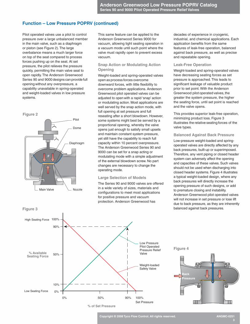
Pilot operated valves use a pilot to controlpressure over a large unbalanced memberin the main valve, such as a diaphragm or piston (see Figure 2). The largeoverbalance means a much larger force on top of the seat compared to processforces pushing up on the seat. At setpressure, the pilot relieves the pressurequickly, permitting the main valve seat toopen rapidly. The Anderson GreenwoodSeries 90 and 9000 designs can provide fullopening without any overpressure, acapability unavailable in spring-operatedand weight-loaded valves in low pressuresystems.
This same feature can be applied to theAnderson Greenwood Series 9000 forvacuum, allowing tight sealing operation ina vacuum mode until such point where thevalve must rapidly open to prevent excessvacuum.
Snap Action or Modulating ActionOpeningWeight-loaded and spring-operated valvesopen as process forces overcomedownward forces, with little flexibility toovercome problem applications. AndersonGreenwood pilot operated valves can beadjusted to open with a rapid ‘snap’ actionor modulating action. Most applications arewell served by the snap action mode, withfull opening at set pressure and fullreseating after a short blowdown. However,some systems might best be served by aproportional opening, whereby the valveopens just enough to satisfy small upsetsand maintain constant system pressure,yet still have the capability to reach fullcapacity within 10 percent overpressure.The Anderson Greenwood Series 90 and9000 can be set for a snap acting ormodulating mode with a simple adjustmentof the external blowdown screw. No partchanges are necessary to change theoperating mode.
Large Selection of ModelsThe Series 90 and 9000 valves are offeredin a wide variety of sizes, materials andconfigurations to meet most applicationsfor positive pressure and vacuumprotection. Anderson Greenwood has
decades of experience in cryogenic,industrial, and chemical applications. Eachapplication benefits from the samefeatures of leak-free operation, balancedagainst back pressure, as well as preciseand repeatable opening.
Leak-Free OperationWeight-loaded and spring-operated valveshave decreasing seating forces as setpressure is approached. This leads tosignificant leakage of valuable productprior to set point. With the AndersonGreenwood pilot operated valves, thegreater the system pressure, the higherthe seating force, until set point is reachedand the valve opens.
This provides superior leak-free operation,minimizing product loss. Figure 3illustrates the relative seating forces of thevalve types.
Balanced Against Back PressureLow-pressure weight-loaded and spring-operated valves are directly affected by anyback pressures, built-up or superimposed.Therefore, any vent piping or closed headersystem can adversely affect the openingand capacities of these valves. Such valvesshould not be used when discharging intoclosed header systems. Figure 4 illustratesa typical weight-loaded design, where anyback pressures will directly increase theopening pressure of such designs, or addto premature closing and instability.Anderson Greenwood pilot operated valveswill not increase in set pressure or lose liftdue to back pressure, as they are inherentlybalanced against back pressures.
Anderson Greenwood Low Pressure POPRV CatalogSeries 90 and 9000 Pilot Operated Pressure Relief Valves
Copyright © 2008 Tyco Flow Control. All rights reserved. ANGMC-02513
Function – Low Pressure POPRV (continued)
BackPressure
Figure 4
0%
% of Set Pressure
% AvailableSeating Force
50% 90% 100%Set Pressure
0%
10%
50%
90%
100%High Seating Force
Low Seating Force
Low PressurePilot OperatedPressure ReliefValve
Weight-loadedSafety Valve
Figure 3
Dome
Main Valve Nozzle
Pilot
Diaphragm
F
Figure 2

Anderson Greenwood Low Pressure POPRV CatalogSeries 90 and 9000 Pilot Operated Pressure Relief Valves
Copyright © 2008 Tyco Flow Control. All rights reserved. ANGMC-02514
Operation – Series 90
Figure 5(Closed)Positive Pressure ReliefUnder normal operating conditions, systempressure acts on the bottom of the mainvalve seat, on top of the main valvediaphragm, and on the pilot diaphragms.The main valve seat is held tightly closedby a large force equal to the systempressure times the unbalanced area of themain valve diaphragm.
System pressure is also applied to theboost cavity and the sense cavitydownstream of the variable orifice.
The soft pilot seat is held closed as thepilot spring load is greater than the upwardforces acting on the sense diaphragm.
Spindle Seal Diaphragm
Sense Diaphragm
Pilot Spring
Boost Diaphragm
Sense Cavity
Boost Cavity
Pilot Seat
Blowdown AdjustmentOrifice (variable)
Main Valve Diaphragm
Fixed Orifice
Dome
Main Valve Seat
Pilot Pickup(total pressure)
System Pressure
Exhaust Pressure
Anderson Greenwood Low Pressure POPRV CatalogSeries 90 and 9000 Pilot Operated Pressure Relief Valves
Copyright © 2008 Tyco Flow Control. All rights reserved. ANGMC-02515
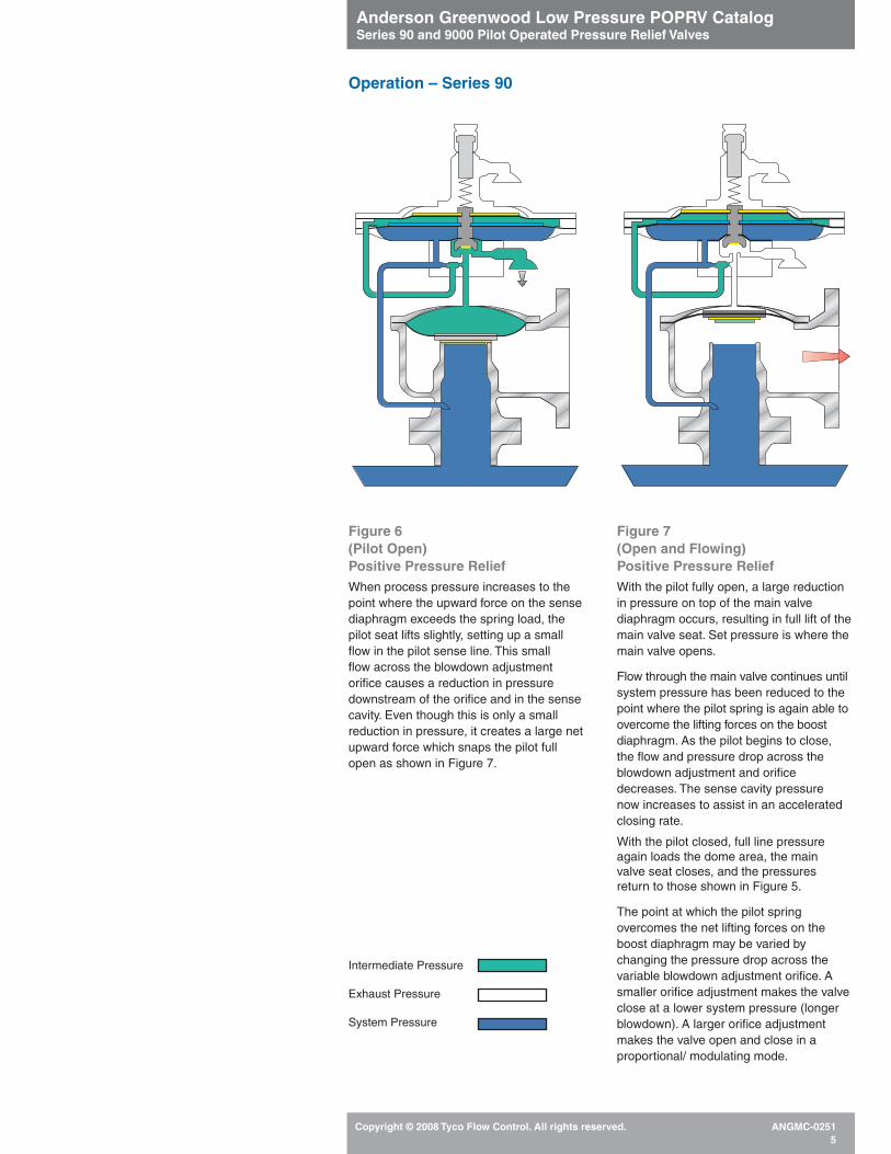
Figure 6(Pilot Open)Positive Pressure ReliefWhen process pressure increases to thepoint where the upward force on the sensediaphragm exceeds the spring load, thepilot seat lifts slightly, setting up a smallflow in the pilot sense line. This small flow across the blowdown adjustmentorifice causes a reduction in pressuredownstream of the orifice and in the sensecavity. Even though this is only a smallreduction in pressure, it creates a large netupward force which snaps the pilot fullopen as shown in Figure 7.
Figure 7(Open and Flowing)Positive Pressure ReliefWith the pilot fully open, a large reductionin pressure on top of the main valvediaphragm occurs, resulting in full lift of themain valve seat. Set pressure is where themain valve opens.
Flow through the main valve continues untilsystem pressure has been reduced to thepoint where the pilot spring is again able toovercome the lifting forces on the boostdiaphragm. As the pilot begins to close, the flow and pressure drop across theblowdown adjustment and orificedecreases. The sense cavity pressure now increases to assist in an acceleratedclosing rate.
With the pilot closed, full line pressureagain loads the dome area, the main valve seat closes, and the pressures return to those shown in Figure 5.
The point at which the pilot springovercomes the net lifting forces on theboost diaphragm may be varied bychanging the pressure drop across thevariable blowdown adjustment orifice. Asmaller orifice adjustment makes the valveclose at a lower system pressure (longerblowdown). A larger orifice adjustmentmakes the valve open and close in aproportional/ modulating mode.
Operation – Series 90
Intermediate Pressure
Exhaust Pressure
System Pressure

Anderson Greenwood Low Pressure POPRV CatalogSeries 90 and 9000 Pilot Operated Pressure Relief Valves
Copyright © 2008 Tyco Flow Control. All rights reserved. ANGMC-02516
Operation – Series 9000 (Positive Pressure Relief)2
Figure 8 Positive Pressure Relief2
The Series 9000 group of productsoperates very similarly to the Series 90group of valves. The Series 90 pilot iswidely used with the Series 9000 valves,available in both ‘snap’ and ‘modulating’actions (see Figures 5 - 7). The maindifference is the main valve diaphragmsare fully supported by the surroundingcases and diaphragm plates, increasingthe pressure ranges of the Teflon®
diaphragms and permitting vacuumoperations. The main valve seat is a highperformance Teflon® film seat which isextended from the main valve diaphragmsto a lower profile nozzle, which permitsgreater flow capacities at set pressure.
Figure 9 Positive Pressure ReliefWhen process pressure increases to thepoint at which the upward force on thesense diaphragm exceeds the pilot springload, the pilot seat lifts and begins the flowthrough the pilot. The flow across theblowdown adjustment orifice can be set torapidly reduce the main valve domepressure for a ‘snap’ action, or slowlyreduce the main valve dome pressure for a‘modulating’ action.1
Figure 10 Positive Pressure Relief• With the pilot open, the dome pressure
is sufficiently reduced and the forcesunder the main valve seat lift the seatplate and begin to relieve systempressure.
• Flow through the main valve continuesuntil system pressure has been reducedenough so the pilot spring is again ableto overcome the lifting forces on theboost diaphragm.
• As the pilot begins to close, the flow andpressure drop across the blowdownadjustment orifice decreases.
• The sense cavity pressure thenincreases to assist in an acceleratedclosing rate.
• With the pilot closed, full line pressureagain loads the dome area and the mainvalve seat closes. Pressures return tothose shown in Figure 8.
• A non-flowing modulating pilot, Series400, is available for special applications.
Spindle Seal Diaphragm
Sense Diaphragm
Pilot Spring
Boost Diaphragm
Sense Cavity
Boost Cavity
Pilot Seat
Blowdown AdjustmentOrifice (variable)
Main Valve Diaphragm
Fixed Orifice
Dome
Main Valve Seat
Pilot Pickup(total pressure)
Pilot Exhaust
Inlet
Figure 9 (Pilot Open) Figure 10 (Open and Flowing)
Figure 8 (Closed)
Intermediate PressureExhaust PressureSystem Pressure

Anderson Greenwood Low Pressure POPRV CatalogSeries 90 and 9000 Pilot Operated Pressure Relief Valves
Copyright © 2008 Tyco Flow Control. All rights reserved. ANGMC-02517
Figure 11 Weight Loaded VacuumReliefWeight loaded vacuum relief is mosttypical for economical vacuum protection incombination with a pilot operated pressurerelief valve.
• The same valve which is held tightlyclosed on positive pressure opens onvacuum based on the weight of internalcomponents.
Figure 12 Weight Loaded VacuumRelief• Vacuum in the protected vessel pulls up
on one or two dome areas while externalatmosphere pushes upwards on thediaphragms to lift the seat plates.
• Vacuum opening pressures depend onvalve internals and number of diaphragmchambers used.
Figure 13 Vacuum Relief PilotOperatedPilot operated vacuum relief operation isbasically the same as positive pressurerelief operation, as follows:
• A seating force is established by loadingthe large dome area with a pressuregreater than the inlet pressure under theseat.
• In the closed condition, atmosphericpressure is present in the dome area ofthe main valve and a vacuum is presentat the inlet. This causes a net force thatcloses the seat and maintains tightnessup to set point.
• At set point, the vacuum pulls against thespring force, and the pilot valve opens,evacuating the dome pressure throughthe supply tube into the inlet vacuum.
Figure 14 Vacuum Relief PilotOperated• With a partial vacuum established in the
dome, atmospheric pressure forces thediaphragm and seat to open andestablishes air flow into the valve. Thisrelieves the system vacuum.
• When the pilot reseats, the supply line isclosed by the pilot seat.
• Atmospheric pressure again fills thedome through the blowdown adjustmentand fixed orifice, which closes the mainvalve.
Operation – Series 9000 (Vacuum Relief)2
Inlet
Pilot Pickup (total pressure)
Inlet
Pilot Pickup (system vacuum)
1. The point at which the pilot spring overcomesthe net lifting forces on the boost diaphragmcan be varied by changing the pressure dropacross the variable blowdown adjustmentorifice. A smaller orifice adjustment makesthe valve close at a lower system pressure(longer blowdown).
2. With either pressure or vacuum configurationalone, the valve will open and flow when theweight-loaded pressure or vacuum for theopposite condition is exceeded unless abackflow preventer is installed.
Notes
Figure 14 (Open and Flowing)Figure 13 (Closed)
Figure 11 (Closed) Figure 12 (Open and Flowing)
Exhaust PressureSystem Pressure

Anderson Greenwood Low Pressure POPRV CatalogSeries 90 and 9000 Pilot Operated Pressure Relief Valves
Copyright © 2008 Tyco Flow Control. All rights reserved. ANGMC-02518
Operation – Type 96A Vacuum Breaker
Atmospheric Pressure
PressureTank
Valve ClosedThe weight of the pallet and any positiveinternal tank pressure holds the valveclosed.
Valve Open and FlowingThe tank vacuum creates a pressuredifferential great enough to overcome theweight of the pallet and the pallet is liftedto the open position.
Retainer Bolts
Seat Ring Retainer
O-ring Seat
Inlet ScreenSeat Ring
Sponge Seat
Seat Plate
Guide TubeBody
Guide RodLifting Eye Bolt
Inlet To Relief Valve Gasket Flange Stud
Flange NutFlange Cap
Tank Connection
Anderson Greenwood Low Pressure POPRV CatalogSeries 90 and 9000 Pilot Operated Pressure Relief Valves
Copyright © 2008 Tyco Flow Control. All rights reserved. ANGMC-02519
1. Not all valve sizes are available for service atextreme limits of both temperature andpressure simultaneously. Please refer tofactory when at limits to confirm suitability ofselected valve.
2. Maximum temperature ratings for Series 90Soft Goods: This is only a guide sincepressure and fluid compatibility will alsoaffect valve selection. See Series 90Temperature Ratings table. For ASME coderequirements, the maximum temperature foraluminum is 250°F [121°C].
3. BUNA-N O-ring main valve seat is rated to -260°F [-162°C] in conjunction with Teflon®
diaphragm.
4. Kalrez®, Viton® and Teflon® are registeredtrademarks of E.I. duPont de NemoursCompany.
5. Hastelloy® is a registered trademark ofHaynes International.
6. Minimum temperature for CS is -20°F [-29°C].
7. Contact the factory for 90 or 9000 Seriesproduct recommendations when the boilingpoint of the lading fluid is in between theminimum and maximum expected ambienttemperatures.
General Technical Data – Refer to Model Selection Tables for Specific Pressure Limitation
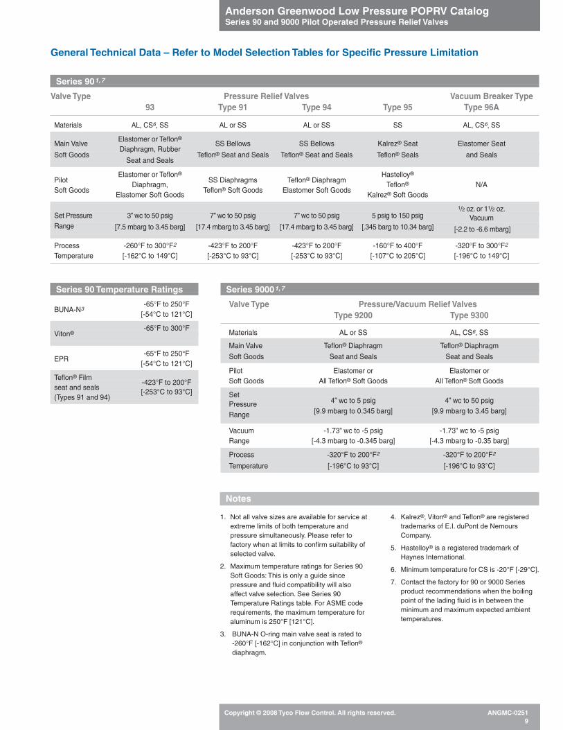
Series 90 Temperature Ratings
BUNA-N3-65°F to 250°F
[-54°C to 121°C]
-65°F to 300°FViton®
EPR-65°F to 250°F
[-54°C to 121°C]
Teflon® Film seat and seals
-423°F to 200°F
(Types 91 and 94)[-253°C to 93°C]
Series 901,7
Valve Type Pressure Relief Valves Vacuum Breaker Type93 Type 91 Type 94 Type 95 Type 96A
Materials AL, CS6, SS AL or SS AL or SS SS AL, CS6, SS
Elastomer or Teflon®Main Valve
Diaphragm, RubberSS Bellows SS Bellows Kalrez® Seat Elastomer Seat
Soft GoodsSeat and Seals
Teflon® Seat and Seals Teflon® Seat and Seals Teflon® Seals and Seals
PilotElastomer or Teflon®
SS Diaphragms Teflon® DiaphragmHastelloy®
Soft GoodsDiaphragm,
Teflon® Soft Goods Elastomer Soft GoodsTeflon® N/A
Elastomer Soft Goods Kalrez® Soft Goods
1/2 oz. or 11/2 oz.Set Pressure 3” wc to 50 psig 7” wc to 50 psig 7” wc to 50 psig 5 psig to 150 psig Vacuum Range [7.5 mbarg to 3.45 barg] [17.4 mbarg to 3.45 barg] [17.4 mbarg to 3.45 barg] [.345 barg to 10.34 barg] [-2.2 to -6.6 mbarg]
Process -260°F to 300°F2 -423°F to 200°F -423°F to 200°F -160°F to 400°F -320°F to 300°F2
Temperature [-162°C to 149°C] [-253°C to 93°C] [-253°C to 93°C] [-107°C to 205°C] [-196°C to 149°C]
Series 90001,7
Valve Type Pressure/Vacuum Relief ValvesType 9200 Type 9300
Materials AL or SS AL, CS6, SS
Main Valve Teflon® Diaphragm Teflon® Diaphragm
Soft Goods Seat and Seals Seat and Seals
Pilot Elastomer or Elastomer or Soft Goods All Teflon® Soft Goods All Teflon® Soft Goods
SetPressure 4” wc to 5 psig 4” wc to 50 psig
Range [9.9 mbarg to 0.345 barg] [9.9 mbarg to 3.45 barg]
Vacuum -1.73” wc to -5 psig -1.73” wc to -5 psigRange [-4.3 mbarg to -0.345 barg] [-4.3 mbarg to -0.35 barg]
Process -320°F to 200°F2 -320°F to 200°F2
Temperature [-196°C to 93°C] [-196°C to 93°C]
Notes
Anderson Greenwood Low Pressure POPRV CatalogSeries 90 and 9000 Pilot Operated Pressure Relief Valves
Copyright © 2008 Tyco Flow Control. All rights reserved. ANGMC-025110
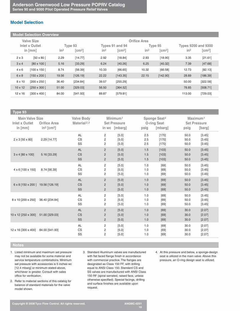
1. Listed minimum and maximum set pressuremay not be available for some material andservice temperature combinations. Minimumset pressure with accessories is 5 inches wc[12.4 mbarg] or minimum stated above,whichever is greater. Consult with salesoffice for verification.
2. Refer to material sections of this catalog forbalance of standard materials for the valvemodel shown.
3. Standard Aluminum valves are manufacturedwith flat faced flange finish in accordancewith commercial practice. The flanges aredesignated as Class 150 FF, with drillingequal to ANSI Class 150. Standard CS andSS valves are manufactured with ANSI Class150 RF (spiral serrated, raised face, unlessotherwise specified). Special facings, drillingand surface finishes are available uponrequest.
4. At this pressure and below, a sponge-designseat is utilized in the main valve. Above thispressure, an O-ring design seat is utilized.
Notes
Type 93
Main Valve Size Valve Body Minimum1 Sponge Seat4 Maximum1
Inlet x Outlet Orifice Area Material2,3 Set Pressure O-ring Seat Set Pressurein [mm] in2 [cm2] in wc [mbarg] psig [mbarg] psig [barg]
AL 2 [5.0] 2.5 [170] 50.0 [3.45]2 x 3 [50 x 80] 2.29 [14.77] CS 2 [5.0] 2.5 [170] 50.0 [3.45]
SS 2 [5.0] 2.5 [170] 50.0 [3.45]
AL 2 [5.0] 1.5 [103] 50.0 [3.45]
3 x 4 [80 x 100] 5.16 [33.29] CS 2 [5.0] 1.5 [103] 50.0 [3.45]
SS 2 [5.0] 1.5 [103] 50.0 [3.45]
AL 2 [5.0] 1.0 [69] 50.0 [3.45]4 x 6 [100 x 150] 8.74 [56.39] CS 2 [5.0] 1.0 [69] 50.0 [3.45]
SS 2 [5.0] 1.0 [69] 50.0 [3.45]
AL 2 [5.0] 1.0 [69] 50.0 [3.45]
6 x 8 [150 x 200 ] 19.56 [126.19] CS 2 [5.0] 1.0 [69] 50.0 [3.45]
SS 2 [5.0] 1.0 [69] 50.0 [3.45]
AL 2 [5.0] 1.0 [69] 50.0 [3.45]8 x 10 [200 x 250] 36.40 [234.84] CS 2 [5.0] 1.0 [69] 50.0 [3.45]
SS 2 [5.0] 1.0 [69] 50.0 [3.45]
AL 2 [5.0] 1.0 [69] 30.0 [2.07]
10 x 12 [250 x 300] 51.00 [329.03] CS 2 [5.0] 1.0 [69] 30.0 [2.07]
SS 2 [5.0] 1.0 [69] 30.0 [2.07]
AL 2 [5.0] 1.0 [69] 30.0 [2.07]12 x 16 [300 x 400] 84.00 [541.93] CS 2 [5.0] 1.0 [69] 30.0 [2.07]
SS 2 [5.0] 1.0 [69] 30.0 [2.07]
Model Selection Overview
Valve Size Orifice AreaInlet x Outlet Type 93 Types 91 and 94 Type 95 Types 9200 and 9300
in [mm] in2 [cm2] in2 [cm2] in2 [cm2] in2 [cm2]
2 x 3 [50 x 80 ] 2.29 [14.77] 2.92 [18.84] 2.93 [18.90] 3.35 [21.61]
3 x 4 [80 x 100 ] 5.16 [33.29] 6.24 [40.26] 6.25 [40.32] 7.39 [47.68]
4 x 6 [100 x 150 ] 8.74 [56.39] 10.33 [66.65] 10.32 [66.58] 12.73 [82.13]
6 x 8 [150 x 200 ] 19.56 [126.19] 22.22 [143.35] 22.15 [142.90] 28.89 [186.39]
8 x 10 [200 x 250 ] 36.40 [234.84] 39.57 [255.29] 50.00 [322.58]
10 x 12 [250 x 300 ] 51.00 [329.03] 56.50 [364.52] 78.85 [508.71]
12 x 16 [300 x 400 ] 84.00 [541.93] 89.87 [579.81] 113.00 [729.03]
Model Selection

Anderson Greenwood Low Pressure POPRV CatalogSeries 90 and 9000 Pilot Operated Pressure Relief Valves
Copyright © 2008 Tyco Flow Control. All rights reserved. ANGMC-025111
Notes
1. Refer to material sections of this catalog forbalance of standard materials for the valvemodel shown.
2. SS valves are standard with ANSI Class 150RF (spiral serrated, raised face, unlessotherwise specified). Special facings, drillingand surface finishes are available uponrequest.
Type 95
Main Valve Size Valve Minimum MaximumInlet x Outlet Orifice Area Body Set Pressure Set Pressure
in [mm] in2 [cm2] Material1,2 psig [barg] psig [barg]
2 x 3 2.93 [50 x 80] [18.90]
SS 10.00 [0.690] 150 [10.3]
3 x 4 6.25
[80 x 100] [40.32]SS 5.00 [0.345] 150 [10.3]
4 x 6 10.32[100 x 150] [66.58]
SS 5.00 [0.345] 150 [10.3]
6 x 8 22.15
[150 x 200] [142.90 ]SS 5.00 [0.345] 150 [10.3]
Notes
1. Listed minimum and maximum set pressuremay not be available for some material andservice temperature combinations. Consultwith sales office for verification.
2. Refer to material sections of this catalog forbalance of standard materials for the valvemodel shown.
3. Standard Aluminum valves are manufacturedwith flat faced flange finish in accordancewith commercial practice. The flanges aredesignated as Class 150 FF, with drillingequal to ANSI Class 150. Standard SS valvesare manufactured with ANSI Class 150 RF(spiral serrated, raised face, unless otherwisespecified). Special facings, drilling andsurface finishes are available upon request.
Model Selection
Types 91 and 94
Main Valve Size Valve Body Minimum1 Maximum1
Inlet x Outlet Orifice Area Material2,3 Set Pressure Set Pressurein [mm] in2 [cm2] psig [mbarg] psig [barg]
2 x 3 2.92 AL 1.50 [103] 50.0 [3.45][50 x 80] [18.84] SS 1.50 [103] 50.0 [3.45]
3 x 4 6.24 AL 1.00 [69] 50.0 [3.45]
[80 x 100] [40.26] SS 1.00 [69] 50.0 [3.45]
4 x 6 10.33 AL 1.00 [69] 50.0 [3.45][100 x 150] [66.65] SS 1.00 [69] 50.0 [3.45]
6 x 8 22.22 AL 1.00 [69] 50.0 [3.45]
[150 x 200] [143.35] SS 1.00 [69] 50.0 [3.45]
8 x 10 39.57 AL 0.75 [52] 50.0 [3.45][200 x 250] [255.29] SS 0.75 [52] 50.0 [3.45]
10 x 12 56.50 AL 0.75 [52] 50.0 [3.45]
[250 x 300] [364.52] SS 0.75 [52] 50.0 [3.45]
12 x 16 89.87 AL 0.50 [34] 50.0 [3.45][300 x 400] [579.81] SS 0.50 [34] 50.0 [3.45]

Notes
1. Listed minimum and maximum set pressuremay not be available for some material andservice temperature combinations. Minimumset pressure with accessories is 5 inches wc[12.4 mbarg] or minimum stated above,whichever is greater. Consult with sales officefor verification.
2. Refer to material sections of this catalog forbalance of standard materials for the valvemodel shown.
3. Standard Aluminum valves are manufacturedwith flat faced outlet flange finish inaccordance with commercial practice. Theflanges are designated as Class 150 FF, withdrilling equal to ANSI Class 150. StandardCS and SS valves are manufactured withANSI Class 150 RF (smooth, raised face,unless otherwise specified). Special facings,drilling and surface finishes are availableupon request. All inlet flanges must be raisedface.
4. 50 psig [3.45 barg] with SS cap.
5. 30 psig [2.07 barg] with SS cap.
6. Valve body available in AL, CS or SS.
Type 9300, Pressure Only - Pilot Operated (single chamber)
Main Valve Size Valve Trim Minimum1 Maximum1
Inlet x Outlet Orifice Area Material2,3,6 Set Pressure Set Pressurein [mm] in2 [cm2] in wc [mbarg] psig [barg]
AL 6 [14.9] 5 [0.35]2 x 3 3.35
SS 6 [14.9] 5 [0.35][50 x 80] [21.61]
SS 19 [47.3] 50 [3.45]
AL 4 [10.0] 5 [0.35]3 x 4 7.39
SS 4 [10.0] 5 [0.35][80 x 100] [47.68]
SS 11 [27.4] 50 [3.45]
AL 3 [7.5] 5 [0.35]4 x 6 12.73
SS 5 [12.4] 5 [0.35][100 x 150] [82.13]
SS 8 [19.9] 444 [3.03]
AL 3 [7.5] 5 [0.35]6 x 8 28.89
SS 5 [12.4] 5 [0.35][150 x 200] [186.39]
SS 6 [14.9] 254 [1.72]
AL 4 [10.0] 5 [0.35]8 x 10 50.00
SS 7 [17.4] 5 [0.35][200 x 250] [322.58]
SS 10 [24.9] 234 [1.59]
AL 4 [10.0] 5 [0.35]10 x 12 78.85
SS 6 [14.9] 2 [0.14][250 x 300] [508.71]
SS 11 [27.4] 145 [0.97]
AL 4 [10.0] 5 [0.35]12 x 16 113.00
SS 10 [24.9] 2 [0.14][300 x 400] [729.03]
SS 17 [42.3] 145 [0.97]
Anderson Greenwood Low Pressure POPRV CatalogSeries 90 and 9000 Pilot Operated Pressure Relief Valves
Copyright © 2008 Tyco Flow Control. All rights reserved. ANGMC-025112
Notes
1. Listed minimum and maximum set pressuremay not be available for some material andservice temperature combinations. Minimumset pressure with accessories is 5 inches wc[12.4 mbarg] or minimum stated above,whichever is greater. Consult with sales officefor verification.
2. Refer to material sections of this catalog forbalance of standard materials for the valvemodel shown.
3. All standard Type 9200 valves aremanufactured with ANSI Class 150 RF inletflanges (smooth, raised face, unlessotherwise specified). Special facings, drillingand surface finishes are available uponrequest.
Model Selection
Type 9200, Pressure Only - Pilot Operated (single chamber)
Main Valve Size Valve Trim Minimum1 Maximum1
Inlet Orifice Area Material2,3 Set Pressure Set Pressurein [mm] in2 [cm2] in wc [mbarg] psig [barg]
2 Vent 3.35 AL 6 [14.9] 5 [0.35][50] [21.61] SS 6 [14.9] 5 [0.35]
3 Vent 7.39 AL 4 [10.0] 5 [0.35]
[80] [47.68] SS 4 [10.0] 5 [0.35]
4 Vent 12.73 AL 3 [7.5] 5 [0.35][100] [82.13] SS 5 [12.4] 5 [0.35]
6 Vent 28.89 AL 3 [7.5] 5 [0.35]
[150] [186.39] SS 5 [12.4] 5 [0.35]
8 Vent 50.00 AL 4 [10.0] 5 [0.35][200] [322.58] SS 7 [17.4] 5 [0.35]
10 Vent 78.85 AL 4 [10.0] 5 [0.35]
[250] [508.71] SS 6 [14.9] 2 [0.14]
12 Vent 113.00 AL 4 [10.0] 5 [0.35][300] [729.03] SS 10 [24.9] 2 [0.14]

Anderson Greenwood Low Pressure POPRV CatalogSeries 90 and 9000 Pilot Operated Pressure Relief Valves
Copyright © 2008 Tyco Flow Control. All rights reserved. ANGMC-025113
Notes
1. Listed minimum and maximum set pressuremay not be available for some material andservice temperature combinations.
2. Refer to material sections of this catalog forbalance of standard materials for the valvemodel shown.
3. All standard Type 9200 valves aremanufactured with ANSI Class 150 RF(smooth, raised face, unless otherwisespecified). Special facings, drilling andsurface finishes are available upon request.
4. Weight loaded vacuum openings areavailable from -1 oz [-4.3 mbarg] full open.Dual chambers may be required.
5. Valve will open on positive pressure unlessequipped with positive pressure blockaccessory. Minimum vacuum set with thisaccessory is limited to -5” wc [-12.4 mbarg].Positive pressure is limited. Please consultfactory.
Model Selection
Type 9200, Vacuum Only - Pilot Operated5 (single chamber)
Main Valve Size Valve Trim Minimum1,4 Maximum1
Inlet Orifice Area Material2,3 Set Vacuum Set Vacuumin [mm] in2 [cm2] in wc [mbarg] psig [barg]
2 Vent 3.35 AL -2 [-5.0] -5 [-0.35][50] [21.61] SS -2 [-5.0] -5 [-0.35]
3 Vent 7.39 AL -2 [-5.0] -5 [-0.35]
[80] [47.68] SS -2 [-5.0] -5 [-0.35]
4 Vent 12.73 AL -2 [-5.0] -5 [-0.35][100] [82.13] SS -2 [-5.0] -5 [-0.35]
6 Vent 28.89 AL -2 [-5.0] -5 [-0.35]
[150] [186.39] SS -2 [-5.0] -5 [-0.35]
8 Vent 50.00 AL -4 [-10.0] -5 [-0.35][200] [322.58] SS -4 [-10.0] -5 [-0.35]
10 Vent 78.85 AL -2 [-5.0] -5 [-0.35]
[250] [508.71] SS -2 [-5.0] -2 [-0.14]
12 Vent 113.00 AL -3 [-7.6] -5 [-0.35][300] [729.03] SS -5 [-12.7] -2 [-0.14]
Notes
1. Listed minimum and maximum set pressuremay not be available for some material andservice temperature combinations.
2. Refer to material sections of this catalog forbalance of standard materials for the valvemodel shown.
3. Standard Aluminum valves are manufacturedwith flat faced outlet flange finish inaccordance with commercial practice. Theflanges are designated as Class 150 FF, withdrilling equal to ANSI Class 150. StandardCS and SS valves are manufactured withANSI Class 150 RF (smooth, raised face,unless otherwise specified). Special facings,drilling and surface finishes are availableupon request. All inlet flanges must be raisedface.
4. Valve body available in AL, CS or SS.
5. Weight loaded vacuum openings areavailable from -1 oz [-4.3 mbarg] full open.Dual chambers may be required.
6. Valve will open on positive pressure unlessequipped with positive pressure blockaccessory. Minimum vacuum set with thisaccessory is limited to -5” wc [-12.4 mbarg].Positive pressure is limited. Please consultfactory.
Type 9300, Vacuum Only - Pilot Operated6 (single chamber)
Main Valve Size Valve Trim Minimum1,5 Maximum1
Inlet x Outlet Orifice Area Material2,3,4 Set Vacuum Set Vacuumin [mm] in2 [cm2] in wc [mbarg] psig [barg]
2 x 3 3.35 AL -2 [-5.0] -5 [-0.35][50 x 80] [21.61] SS -2 [-5.0] -5 [-0.35]
3 x 4 7.39 AL -2 [-5.0] -5 [-0.35]
[80 x 100] [47.68] SS -2 [-5.0] -5 [-0.35]
4 x 6 12.73 AL -2 [-5.0] -5 [-0.35][100 x 150] [82.13] SS -2 [-5.0] -5 [-0.35]
6 x 8 28.89 AL -2 [-5.0] -5 [-0.35]
[150 x 200] [186.39] SS -2 [-5.0] -5 [-0.35]
8 x 10 50.00 AL -4 [-10.0] -5 [-0.35][200 x 250] [322.58] SS -4 [-10.0] -5 [-0.35]
10 x 12 78.85 AL -2 [-5.0] -5 [-0.35]
[250 x 300] [508.71] SS -2 [-5.0] -5 [-0.35]
12 x 16 113.00 AL -3 [-7.6] -5 [-0.35][300 x 400] [729.03] SS -5 [-12.7] -5 [-0.35]

Anderson Greenwood Low Pressure POPRV CatalogSeries 90 and 9000 Pilot Operated Pressure Relief Valves
Copyright © 2008 Tyco Flow Control. All rights reserved. ANGMC-025114
Notes
1. Listed minimum and maximum set pressuremay not be available for some material andservice temperature combinations. Consultwith sales office for verification.
2. Refer to material sections of this catalog forbalance of standard materials for the valvemodel shown.
3. Aluminum and SS valves are manufacturedwith raised faced inlet flange finish inaccordance with commercial practice. Theflanges are designated as Class 150 RF.
4. With dual diaphragm chambers, valvereaches rated capacity at -1 oz [-4.3 mbarg].Note that 2-inch valve only requires singlediaphragm chamber. Pilot operated control ofvacuum setting is available. Please consultfactory.
Model Selection
Type 9200, Pressure Pilot Weight Loaded Vacuum Combination4
(dual chamber)
Main Valve Size Valve Pressure1
Inlet Orifice Area Trim Material2,3 Pilot Rangein [mm] in2 [cm2]
2 3.35AL
6” wc to 5 psig[50] [21.61] [14.9 mbarg to 0.35 barg]
2 3.36 6” wc to 5 psig
[50] [21.68]SS
[14.9 mbarg to 0.35 barg]
3 7.39AL
4” wc to 5 psig [80] [47.68] [10 mbarg to 0.35 barg]
3 7.39 4” wc to 5 psig
[80] [47.68]SS
[10 mbarg to 0.35 barg]
4 12.73AL
3” wc to 5 psig[100] [82.13] [7.5 mbarg to 0.35 barg]
4 12.73 5” wc to 5 psig
[100] [82.13]SS
[12.4 mbarg to 0.35 barg]
6 28.89AL
3” wc to 5 psig[150] [186.39] [7.5 mbarg to 0.35 barg]
6 28.89 5” wc to 5 psig
[150] [186.39]SS
[12.4 mbarg to 0.35 barg]
8 50.00AL
4” wc to 5 psig[200] [322.58] [10 mbarg to 0.35 barg]
8 50.00 7” wc to 5 psig
[200] [322.58]SS
[17.4 mbarg to 0.35 barg]
10 78.85AL
4” wc to 5 psig[250] [508.71] [10 mbarg to 0.35 barg]
10 78.85 6” wc to 2 psig
[250] [508.71]SS
[14.9 mbarg to 0.14 barg]
12 113.00AL
4” wc to 5 psig[300] [729.03] [10 mbarg to 0.35 barg]
12 113.00 10” wc to 2 psig
[300] [729.03]SS
[24.9 mbarg to 0.14 barg]

Anderson Greenwood Low Pressure POPRV CatalogSeries 90 and 9000 Pilot Operated Pressure Relief Valves
Copyright © 2008 Tyco Flow Control. All rights reserved. ANGMC-025115
Type 9300, Pressure Pilot Weight Loaded Vacuum Combination7
(dual chamber)
Main Valve Size Valve Internals Pressure1
Inlet Orifice Area Material2,3,6 Pilot Rangein [mm] in2 [cm2]
2 x 3 3.35AL
6” wc to 5 psig[50 x 80] [21.61] [14.9 mbarg to 0.35 barg]
3.36 6” wc to 5 psig
2 x 3 [21.68] [14.9 mbarg to 0.35 barg]
[50 x 80] 3.36SS
20” wc to 50 psig
[21.68] [48.8 mbarg to 3.45 barg]
3 x 4 7.39AL
4” wc to 5 psig[80 x 100] [47.68] [10 mbarg to 0.35 barg]
7.39 4” wc to 5 psig
3 x 4 [47.68] [10 mbarg to 0.35 barg]
[80 x 100] 7.39SS
12” wc to 50 psig
[47.68] [29.9 mbarg to 3.45 barg]
4 x 6 12.73AL
3” wc to 5 psig[100 x 150] [82.13] [7.5 mbarg to 0.35 barg]
12.73 5” wc to 5 psig
4 x 6 [82.13] [12.4 mbarg to 0.35 barg]
[100 x 150] 12.73SS
9” wc to 44 psig4
[82.13] [22.4 mbarg to 3.03 barg]
6 x 8 28.89AL
3” wc to 5 psig[150 x 200] [186.39] [7.5 mbarg to 0.35 barg]
28.89 5” wc to 5 psig
6 x 8 [186.39] [12.4 mbarg to 0.35 barg]
[150 x 200] 28.89SS
7” wc to 25 psig4
[186.39] [17.4 mbarg to 1.72 barg]
8 x 10 50.00AL
4” wc to 5 psig[200 x 250] [322.58] [10 mbarg to 0.35 barg]
50.00 7” wc to 5 psig
8 x 10 [322.58] [17.4 mbarg to 0.35 barg]
[200 x 250] 50.00SS
11” wc to 23 psig4
[322.58] [27.4 mbarg to 1.59 barg]
10 x 12 78.85AL
4” wc to 5 psig[250 x 300] [508.71] [10 mbarg to 0.35 barg]
78.85 6” wc to 2 psig
10 x 12 [508.71] [14.9 mbarg to 0.14 barg]
[250 x 300] 78.85SS
12” wc to 14 psig5
[508.71] [29.9 mbarg to 0.97 barg]
12 x 16 113.00AL
4” wc to 5 psig[300 x 400] [729.03] [10 mbarg to 0.35 barg]
113.00 10” wc to 2 psig
12 x 16 [729.03] [24.9 mbarg to 0.14 barg]
[300 x 400] 113.00SS
19” wc to 14 psig5
[729.03] [47.3 mbarg to 0.97 barg]
Notes
1. Listed minimum and maximum set pressuremay not be available for some material andservice temperature combinations. Consultwith sales office for verification.
2. Refer to material sections of this catalog forbalance of standard materials for the valvemodel shown.
3. Standard Aluminum valves are manufacturedwith flat faced outlet flange finish inaccordance with commercial practice. Theflanges are designated as Class 150 FF, withdrilling equal to ANSI Class 150. StandardCS and SS valves are manufactured withANSI Class 150 RF (smooth, raised face,unless otherwise specified). Special facings,drilling and surface finishes are availableupon request.
4. 50 psig [3.45 barg] with SS cap.
5. 30 psig [2.07 barg] with SS cap.
6. Valve body available in AL, CS or SS.
7. With dual diaphragm chambers, valvereaches rated capacity at -1 oz [-4.3 mbarg].Note that 2-inch valve only requires singlediaphragm chamber. Pilot operated control ofvacuum setting is available. Please consultfactory.
Model Selection

Anderson Greenwood Low Pressure POPRV CatalogSeries 90 and 9000 Pilot Operated Pressure Relief Valves
Copyright © 2008 Tyco Flow Control. All rights reserved. ANGMC-025116
1. All model numbers shown are standard.Some alternative flange facing or drilling isavailable upon request.
2. The pressure relief valve connection is drilledto meet the size and number of bolts forANSI Class 150 flanges.
3. Standard Settings: -1/2 oz [-2.2 mbarg] -11/2 oz [-6.6 mbarg]
Full open at double this setting.
4. Seat and seals available in BUNA-N, Viton®
and EPR.
Notes
Model Selection
Type 96A Vacuum Breaker1
Tank Connection Safety Valve ConnectionValve Size ANSI Flange Valve Body Valve Size ANSI Flange Maximum Valve Model
in [mm] Class2 Material in [mm] Class2 Positive Pressure Number3,4
4 [100]150 FF AL
Capped150 FF 85 psig [5.86 barg] 96A04FA
150 RF SS 150 FF 85 psig [5.86 barg] 96A04RS
150 FF AL 150 FF 85 psig [5.86 barg] 96A0404FA4 [100]
150 RF SS4 [100]
150 FF 85 psig [5.86 barg] 96A0404RS
4 [100]150 FF AL
3 [80]150 FF 85 psig [5.86 barg] 96A0403FA
150 RF SS 150 FF 85 psig [5.86 barg] 96A0403RS
150 FF AL 150 FF 37 psig [2.55 barg] 96A06FA6 [150]
150 RF SSCapped
150 FF 37 psig [2.55 barg] 96A06RS
6 [150]150 FF AL
6 [150]150 FF 37 psig [2.55 barg] 96A0606FA
150 RF SS 150 FF 37 psig [2.55 barg] 96A0606RS
150 FF AL 150 FF 37 psig [2.55 barg] 96A0604FA6 [150]
150 RF SS4 [100]
150 FF 37 psig [2.55 barg] 96A0604RS
8 [200]150 FF AL
Capped150 FF 65 psig [4.48 barg] 96A08FA
150 RF SS 150 FF 65 psig [4.48 barg] 96A08RS
150 FF AL 150 FF 65 psig [4.48 barg] 96A0808FA8 [200]
150 RF SS8 [200]
150 FF 65 psig [4.48 barg] 96A0808RS
8 [200]150 FF AL
6 [150]150 FF 65 psig [4.48 barg] 96A0806FA
150 RF SS 150 FF 65 psig [4.48 barg] 96A0806RS
150 FF AL 150 FF 44 psig [3.03 barg] 96A12FA12 [300]
150 RF SSCapped
150 FF 44 psig [3.03 barg] 96A12RS
12 [300]150 FF AL
12 [300]150 FF 44 psig [3.03 barg] 96A1212FA
150 RF SS 150 FF 44 psig [3.03 barg] 96A1212RS
150 FF AL 150 FF 44 psig [3.03 barg] 96A1210FA12 [300]
150 RF SS10 [250]
150 FF 44 psig [3.03 barg] 96A1210RS

Anderson Greenwood Low Pressure POPRV CatalogSeries 90 and 9000 Pilot Operated Pressure Relief Valves
Copyright © 2008 Tyco Flow Control. All rights reserved. ANGMC-025117
Materials of Construction
Part # Description MaterialAL CS SS
1 Cap CS1 SA516-701 CS SA516-701 SS A240-316
2 Retainer Plate AL 6061-T6511 AL 6061-T6511 SS A240-304
3 Guide Spring6 316 SS 316 SS 316 SS
4 Spring Pin2 302 SS 302 SS 302 SS
5 Guide6 AL 6061-T61 AL 6061-T61 7
6 Dipper Tube 17-4 SS 17-4 SS 17-4 SS
7 Seat O-ring 3 3 3
8 Diaphragm 4 4 4
9 Body AL SB26 356-T6 CS A216-WCB SS A351-CF8M
10 Diaphragm Retainer AL 6061-T61 AL 6061-T61 SS A240-304
11 Seat Retainer AL 6061-T61 AL 6061-T61 SS A240-304
12 Sponge Seat 3 3 3
13 Top Plate8 AL 6061-T61 AL 6061-T61 SS A240-304
14 Pilot Valve AL1 CS1 SS
15 Nozzle SS 479-316 or A351-CF8M CS1,5 A108-1213 or A513-1026 SS 479-316 or A351-CF8M
– Nuts/Bolts/Tubing 18-8 SS 18-8 SS 18-8 SS
Product Detail – Type 93
• ASME UV Code Stamp, NBcertified capacity 15 psig andabove
• Elastomer or Teflon® Diaphragms
• Replaceable Nozzles
• Elastomer Seat and Seals
• Pressure Range2-inch wc to 50 psig [5.0 mbarg to 3.45 barg]
• Sizes 2 to 12- inch [50 to 300 mm]
• Orifices 2.29 to 84.0 in2
[14.78 to 541.97 cm2]
Notes
1. SS optional.
2. Used on 6-inch [150 mm] and larger valvesonly.
3. BUNA-N standard, Viton® or EPR optional.
4. Buna-N, Dacron reinforced standard; Viton®,EPR, Dacron reinforced optional; non-reinforced Teflon® optional.
5. Electroless Nickel plated.
6. Not required in lowest pressure.
7. 2- to 6-inch [50 thru 150 mm]:A747-CB7CU1H1150.
8- to 12-inch [200 thru 300 mm]:A240-304/A276-304/A312-304W.
8. Used on 6-inch [150 mm] and smaller valves.
14
13
10
8
11
7
5
6
15
4
3
1
12
11
10
2
9
O-ring Seat
Sponge Seat
Anderson Greenwood Low Pressure POPRV CatalogSeries 90 and 9000 Pilot Operated Pressure Relief Valves
Copyright © 2008 Tyco Flow Control. All rights reserved. ANGMC-025118
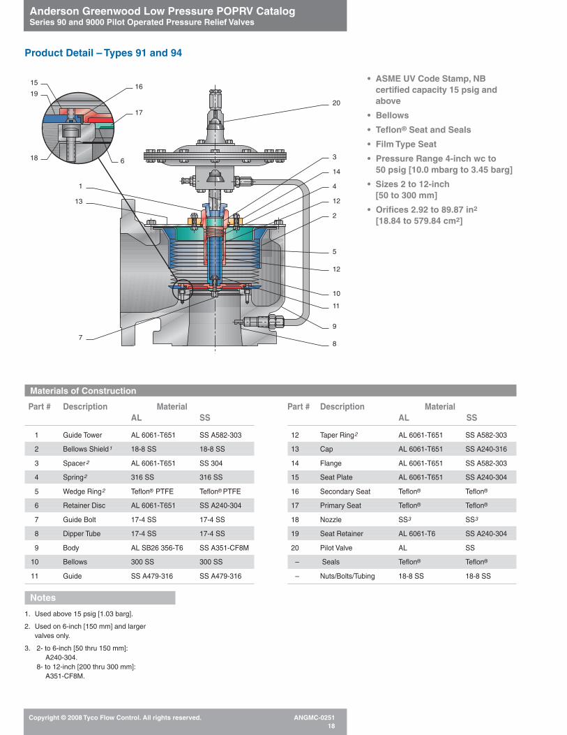
Part # Description MaterialAL SS
1 Guide Tower AL 6061-T651 SS A582-303
2 Bellows Shield1 18-8 SS 18-8 SS
3 Spacer2 AL 6061-T651 SS 304
4 Spring2 316 SS 316 SS
5 Wedge Ring2 Teflon® PTFE Teflon® PTFE
6 Retainer Disc AL 6061-T651 SS A240-304
7 Guide Bolt 17-4 SS 17-4 SS
8 Dipper Tube 17-4 SS 17-4 SS
9 Body AL SB26 356-T6 SS A351-CF8M
10 Bellows 300 SS 300 SS
11 Guide SS A479-316 SS A479-316
Part # Description MaterialAL SS
12 Taper Ring2 AL 6061-T651 SS A582-303
13 Cap AL 6061-T651 SS A240-316
14 Flange AL 6061-T651 SS A582-303
15 Seat Plate AL 6061-T651 SS A240-304
16 Secondary Seat Teflon® Teflon®
17 Primary Seat Teflon® Teflon®
18 Nozzle SS3 SS3
19 Seat Retainer AL 6061-T6 SS A240-304
20 Pilot Valve AL SS
– Seals Teflon® Teflon®
– Nuts/Bolts/Tubing 18-8 SS 18-8 SS
Notes
1. Used above 15 psig [1.03 barg].
2. Used on 6-inch [150 mm] and larger valves only.
3. 2- to 6-inch [50 thru 150 mm]:A240-304.
8- to 12-inch [200 thru 300 mm]:A351-CF8M.
Product Detail – Types 91 and 94
• ASME UV Code Stamp, NBcertified capacity 15 psig andabove
• Bellows
• Teflon® Seat and Seals
• Film Type Seat
• Pressure Range 4-inch wc to 50 psig [10.0 mbarg to 3.45 barg]
• Sizes 2 to 12-inch [50 to 300 mm]
• Orifices 2.92 to 89.87 in2
[18.84 to 579.84 cm2]
Materials of Construction
20
3
12
10
11
9
87
1
16
18
15
19
13
14
4
12
2
5
17
6

Anderson Greenwood Low Pressure POPRV CatalogSeries 90 and 9000 Pilot Operated Pressure Relief Valves
Copyright © 2008 Tyco Flow Control. All rights reserved. ANGMC-025119
• ASME UV Code Stamp, NBcertified capacity 15 psig andabove
• Piston Moving Member
• Kalrez® Elastomer Seat,Teflon®
Seals
• Pressure Range 5 to 150 psig [0.345 to 10.34 barg]
• Sizes 2 to 6-inch [50 to 150 mm]
• Orifices 2.93 to 22.15 in2
[18.90 to 142.90 cm2]
Materials of Construction
Part # Description MaterialSS
1 Body SS A351-CF8M
2 Cap/Liner SS A479-3161
3 Nozzle SS A479-316
4 Seat Kalrez®2
5 Piston SS A479-3163
6 Cap Gasket Teflon® PTFE
7 Dipper Tube 17-7 SS
8 Nozzle Gasket Teflon® PTFE
9 Seat Retainer SS A582-3034
10 Seat Retainer Seal Teflon® PTFE
11 Piston Seal Teflon® PTFE
12 Pilot Valve SS
– Nuts/Bolts/Tubing 18-8 SS
Notes
1. Optional SS A351-CF8M.
2. duPont Co. Perfluoroelastomer.
3. 4- and 6-inch [100 and 150 mm]:A351-CF8M.
4. 4- and 6-inch [100 and 150 mm]:A240-316.
Product Detail – Type 95
12
2
3
87
4
9
11
6
10
1
5

Anderson Greenwood Low Pressure POPRV CatalogSeries 90 and 9000 Pilot Operated Pressure Relief Valves
Copyright © 2008 Tyco Flow Control. All rights reserved. ANGMC-025120
Materials of Construction
Part # Description MaterialAL SS
1 Pilot AL SS
2 Auxiliary Actuator Support SS 316 SS 316
3 Diaphragms FEP FEP
4 Shield AL B209-6061-0 SS A240-304
5 Shaft AL B211-6061-T6 SS 316
6 Screen SS 304 SS 304
7 Base Flange AL B209-6061-T6 SS A351-CF8M
8 Film Seat FEP FEP
9 Nozzle SS A351-CF8M SS A351-CF8M
10 Seat Plate AL B209-6061-T62 SS A240-316
11 Support Column SS A479-304 SS A479-304
12 Auxiliary Rod SS A276-316 SS A276-316
13 Primary Actuator Case AL SB209-6061-T4 SS A240-304/316
14 Adaptor1 SS 17-4 SS 17-4
15 Auxiliary Actuator Case1 AL SB209-6061-T4 SS A240-304/316
16 Inlet Studs CS A193-B7 SS A193-B8M
Product Detail – Type 9200 Vent
1
2
3
4
5
6
7
10
8
9
11
12
13
14
3
15
Pilot Inlet
16
• Protected FEP Teflon®
Diaphragms
• Film Type Main Valve Seat
• Elastomer or Teflon® Pilot Seatand Seals Available
• Vents Direct to Atmosphere
• Pressure Range 4-inch wc to 5 psig[10.0 mbarg to 0.345 barg]
• Vacuum Range -1 oz [-4.3 mbarg] full open weightloaded-2-inch wc to -5 psig pilot operated[-5.0 mbarg to -0.345 barg]
• Sizes 2 to 12-inch [50 to 300 mm]
• Orifices 3.35 to 113.00 in2
[21.61 to 729.03 cm2]
Notes
1. Only supplied for certain vacuum conditions.
2. Also available in SS.
Single Chamber

Anderson Greenwood Low Pressure POPRV CatalogSeries 90 and 9000 Pilot Operated Pressure Relief Valves
Copyright © 2008 Tyco Flow Control. All rights reserved. ANGMC-025121
Product Detail – Type 9300
Materials of Construction
Part # Description MaterialAL CS SS
1 Pilot AL CS SS
2 Auxiliary Actuator Support SS 316 SS 316 SS 316
3 Auxiliary Rod SS A276-316 SS A276-316 SS A276-316
4 Diaphragms FEP FEP FEP
5 Body AL SB26 356-T6 CS SA216-WCB SS SA351-CF8M
6 Shaft AL B211-6061-T6 SS 316 SS 316
7 Film Seat FEP FEP FEP
8 Nozzle SS A351-CF8M SS A351-CF8M SS A351-CF8M
9 Seat Plate AL B209-6061-T62 SS A240-316 SS A240-316
10 Primary Actuator Case AL SB209-6061-T4/T451 CS SA516-70 SS A240-304/316
11 Adapter1 SS 17-4 SS 17-4 SS 17-4
12 Auxiliary Actuator Case1 AL SB209-6061-T4/T451 CS SA516-70 SS A240-304/316
13 Pressure Support Plate AL B209-6061-T62 SS A240-304 SS A240-304
14 Vacuum Support Plate AL B209-6061-T62 SS A240-304 SS A240-304
15 Inlet Stud CS A193-B7 CS A193-B7 SS A193-B8M
PilotInlet
1
2
3
4
5
13
6
9
7815
12
4
11
10
14
• ASME UV Code Stamp, NBcertified capacity 15 psig andabove
• Protected FEP Teflon® Diaphragms
• Film Type Main Valve Seat
• Elastomer or Teflon® Pilot Seatand Seals Available
• Vents Direct to Atmosphere
• Balanced Against Back Pressure
• Pressure Range 4-inch wc to 50 psig[10.0 mbarg to 3.45 barg]
• Vacuum Range -1 oz [-4.3 mbarg] full open weightloaded-2-inch wc to -5 psig pilot operated[-5.0 mbarg to -0.345 barg]
• Sizes 2 to 12-inch [50 to 300 mm]
• Orifices 3.35 to 113.00 in2
[21.61 to 729.03 cm2]
Notes
1. Only supplied for certain vacuum conditions.
2. Also available in SS.
Single Chamber
Dual Chamber

Anderson Greenwood Low Pressure POPRV CatalogSeries 90 and 9000 Pilot Operated Pressure Relief Valves
Copyright © 2008 Tyco Flow Control. All rights reserved. ANGMC-025122
12
24
16
25
12
24
13
25
23
21
Supply
2
15
20
18
9
15
22
14
8
11
1
19
1210
7
17
65
1
4
3
Types 93 and 94
View A-A
Types 91 and 93T Seat Teflon®
Type 95 Seat Kalrez®3 O-ring
Product Detail – Series 90 Pilot Construction

Anderson Greenwood Low Pressure POPRV CatalogSeries 90 and 9000 Pilot Operated Pressure Relief Valves
Copyright © 2008 Tyco Flow Control. All rights reserved. ANGMC-025123
Materials of Construction
Part # Description MaterialAL CS SS
1 Cap CS AX/ZN/CO CS AX/ZN/CO SS A582-303
2 Pressure Adjustment Bolt SS A276-316 SS A276-316 SS A276-316
3 Bonnet SS A351-CF8M SS A351-CF8M SS A351-CF8M
4 Spring 316 SS 316 SS 316 SS
5 Sense Plate AL 6061-T6 CS 1010 ZN/CO 304 SS
6 Upper Case CS A367 CS A367 304 SS
7 Spacer Ring CS A367 CS A367 304 SS
8 Lower Case CS A367 CS A367 304 SS
9 Boost Spacer AL 2617-T451 304 SS 304 SS
10 Spindle Diaphragm 1 1 1
11 Seat (Types 93 and 94) 2 2 2
12 Nozzle SS A351-CF8M SS A351-CF8M SS A351-CF8M
13 Seat (Type 91) Teflon® Teflon® Teflon®
14 Body AL 6061-T651 CS 1117 Ni Pl SS A479-316/316L
15 Vent Zytel Zytel Zytel
16 Seat (Type 95) Kalrez®3 Kalrez®3 Kalrez®3
17 Check Plate 304 SS5 304 SS5 304 SS5
18 Diaphragms 6 6 6
19 Boost Plate AL 6061-T6 CS 1010 ZN/CO 304 SS
20 Sense Spacer 316 SS 316 SS 316 SS
21 Blowdown Needle SS A276-316 SS A276-316 SS A276-316
22 Body Bolt Seal 4 4 4
23 Filter Screen 316 SS 316 SS 316 SS
24 Seat Retainer SS SA479-304 SS SA479-304 SS SA479-304
25 Retainer Ring SS PH15-7M0 SS PH15-7M0 SS PH15-7M0
– Nuts/Bolts/Tubing 18-8 SS 18-8 SS 18-8 SS
1. Types 91 and 95 - SSTypes 93 and 94 - BUNA-N standard; Viton®,EPR or Teflon® optional.
2. BUNA-N standard; Viton® or EPR optional.
3. duPont Co. Perfluoroelastomer.
4. Types 91 and 95 - Teflon®
Type 93 - BUNA-N standard; Viton® or EPRoptional.
5. Types 91, 94 and 95 - PCTFEType 93 - BUNA-N standard; Viton® or EPRoptional.
6. Type 91 - SS/Teflon®
Type 95 - Hastelloy®/Teflon®
Types 93 and 94 - BUNA-N standard; Viton®,EPR, or Teflon® optional.
7. SS optional.
Notes
Product Detail – Series 90 Pilot

Anderson Greenwood Low Pressure POPRV CatalogSeries 90 and 9000 Pilot Operated Pressure Relief Valves
Copyright © 2008 Tyco Flow Control. All rights reserved. ANGMC-025124
Product Detail – Series 400 No-Flow Modulating Pilot
Materials of ConstructionPart # Description Material
1 Spring 316 SS
2 Sensing Diaphragm FEP
3 Feedback Diaphragm FEP
4 Spool SS A479-316
5 Body SS A479-316
6 Bonnet Assembly SS A351-CF8M
7 Inlet Screen 316 SS
8 Outlet Seat 1
9 Inlet Seat 1
10 Spindle Assembly SS A276-316
11 Upper Diaphragm Case 304 SS
12 Lower Diaphragm Case 304 SS
13 Pressure Adjusting Screw SS A276-316
14 Bonnet Cap SS A582-303
Note
1. BUNA-N standard; Viton® or EPR optional.
8
2
3
10
1
To PressureActuator
45
9
7To Vacuum Actuator
PilotInlet
6 11
12
14
13

Anderson Greenwood Low Pressure POPRV CatalogSeries 90 and 9000 Pilot Operated Pressure Relief Valves
Copyright © 2008 Tyco Flow Control. All rights reserved. ANGMC-025125
14 9 7 8 2
6
5
3
1 4 15 Inlet ToRelief Valve
13 11 1210
Tank Connection
Product Detail – Type 96A
Materials of Construction
Part Description Material# AL CS SS
1 Body AL ASTM-B26 356-T6 CS SA216-WCB SS A351-CF8M
2 Seat Ring AL 6061-T6 SS A240-316 SS A240-316
3 Guide Tube SS A269-316W/D SS A269-316W/D SS A269-316W/D
303 SS Teflon® 303 SS Teflon® 303 SS Teflon®4 Guide Rod
Coated Coated Coated
5 Seat Plate SS A240-316 SS A240-316 SS A240-316
6 Sponge Seat 1 1 1
7 O-ring Seat 1 1 1
304 SS, 1” Mesh 304 SS, 1” Mesh 304 SS, 1” Mesh8 Inlet Screen 0.08-inch Wire 0.08-inch Wire 0.08-inch Wire
Diameter Diameter Diameter
9Seat Ring
SS A240-316 SS A240-316 SS A240-316Retainer
10 Flange Cap AL 6061-T62 SS A240-3162 SS A240-3162
11 Flange Stud 316 SS2 316 SS2 316 SS2
12 Flange Nut 18-8 SS2 18-8 SS2 18-8 SS2
13 Gasket Teflon2 Teflon®2 Teflon®2
14 Retainer Bolts SS 18-8 SS 18-8 SS 18-8
15 Lifting Eye Bolt CS A307 CS A307 CS A307
Notes
1. BUNA-N standard; Viton®, EPR optional.
2. Furnished on vacuum breakers without relief valve connection.
• 1/2 oz. [2.2 mbarg] Standard Vacuum Setting; 11/2 oz.[6.6 mbarg] Optional
• Aluminum or SS
• Sizes 4-, 6-, 8-, and 12-inch[100, 150, 200, and 300 mm]
Tank Connection Maximum AllowableSize Positive Pressure
4-inch [100 mm] 85 psig [5.86 barg]
6-inch [150 mm] 37 psig [2.55 barg]
8-inch [200 mm] 65 psig [4.48 barg]
12-inch [300 mm] 44 psig [3.03 barg]
Vacuum breakers and pressure reliefvalves can be mounted together.

Anderson Greenwood Low Pressure POPRV CatalogSeries 90 and 9000 Pilot Operated Pressure Relief Valves
Copyright © 2008 Tyco Flow Control. All rights reserved. ANGMC-025126
In addition to the beneficial featuresavailable through the use of the Series 90and 9000 pilot operated pressure reliefvalves, a variety of accessories andoptions are available to provide additionalfunctions. Some simplify the process ofperiodic testing, an important safetyrequirement today. Others assist in thesuccessful operation of the pressure reliefvalve under adverse or specialapplications.
Please refer to the options and accessoriesavailability table on page 29. On request,other options may be available for somemodels for special situations, such asposition indicators, purge connections,multiple pilots, differential pressure sensing,etc.
A. Field Test Connection:• In-service verification of set pressure.
• Simplifies the periodic testing ofpressure relief valves.
All Series 90 and 9000 pilot operatedpressure relief valves may be readilytested for verification of set pressureduring normal operation with this option,using an external pressure source and atest gauge. When the test pressureequipment is initially connected, the testgauge will indicate current systempressure, if any. When test pressure isslowly admitted through a metering valve,the pilot and the main valve dome arepressurized, simulating an increasedsystem pressure.
When set pressure is reached the pilot willactuate. This actuation pressure may thenbe compared with the nameplate value.Depending upon the current value ofsystem pressure, the main valve may alsobriefly open and close, or partially openand close, providing verification that themain valve will successfully operate.Special provisions are available totemporarily prevent main valve openingduring this test (consult with yourrepresentative for details).
The standard Field Test Connection isshown in Figure A1. With this style, anyoverpressure condition during testing willoverride the test pressure and open thevalve.
A three-way ball valve shown in Figure A2must be used for the Field Test Connectionwhen any vacuum opening is required ofthe valves, as the check valve above wouldprevent a vacuum signal from reaching thepilot. This style of Field Test Connectionmust also be used with the Type 400 non-flowing modulating pilot.
• A Field Test Connection isrecommended when a BackflowPreventer is specified in order to providea means to evacuate trapped domepressure before disassembly.
B. Backflow Preventer:
• Prevents accidental reverse flowthrough pressure relief valve.
This option, sometimes called a ‘vacuumblock,’ prevents a pilot operated pressurerelief valve from reverse flow whensufficient vacuum is present at the inletflange. The Backflow Preventer alsoprevents reverse flow when the pressure atthe outlet flange (superimposed backpressure) is greater than the currentsystem pressure. Reverse flow will occurwith any standard type or design of pilotoperated pressure relief valve whensufficient reverse differential pressureexists.
All backflow preventers operate bypermitting the introduction of outletpressure into the dome of the main valve,thereby holding the unbalanced movingelement firmly onto the nozzle, overcomingthe effect of a reverse differential pressureacross the pressure relief valve. The optionalso includes a provision to preventreverse flow through the pilot supply lineback into the system.
A Backflow Preventer should be specifiedwhenever:
• A vacuum may be present at the inletconnection due to unusual operatingconditions or a temporary vacuumcondition may occur under startupconditions.
• The discharge of the pressure reliefvalve is connected to a downstreampressure vessel, where pressure mayvary from time to time, in excess of thepressure in the upstream system.
• The discharge of multiple pressure reliefvalves is combined into a single manifoldor vent system, creating superimposedback pressures in excess of the currentupstream system pressure.
• A pilot operated vacuum valve isspecified and the valve must remainclosed on positive pressure.
B. Backflow Preventer
Options and Accessories
A1. Field Test Connection
A2. Field Test Connection

Anderson Greenwood Low Pressure POPRV CatalogSeries 90 and 9000 Pilot Operated Pressure Relief Valves
Copyright © 2008 Tyco Flow Control. All rights reserved. ANGMC-025127
Options and Accessories
C. Pilot Supply Filter:• Protects pilot from excessive particulate
matter in flow stream.
This is a mechanical filter available forapplications where there is a possibility oflarge amounts of particulate matter in thefluid stream. The Pilot Supply Filter ismounted to the main valve cap. A filterdrain valve is optionally available.
D. Remote Valve Lift Indicator:• Provides remote signal to allow the plant
operator to know when a safety valvehas operated.
This feature consists of a differentialpressure switch, actuated when the mainvalve has been operated. The switch isadjusted to sense the difference betweenthe system pressure and the main valvedome pressure. Electrical indication is then available to a remote location. The switchcontact style and rating, as well as the typeof enclosure and hazard rating, should befurnished. The switch is mounted to themain valve cap.
Please note that this method of indicationis indirect, since it only indicates that pilotactuation has occurred and the necessarydome pressure reduction has taken place.Direct mechanical position indication is notavailable.
E. Auxiliary Setters:• Allows the primary pilot to be set easily
to a second or third set pressure.
This system is widely used aboard shipswhere it is desirable to have different setpressures when under differentjurisdictions or when a ship is in port.
The accessory consists of additionalsprings which are fitted to the primary pilot.
C. Pilot Supply Filter
D. Remote Valve Lift Indicator
E. Auxiliary Setters

Anderson Greenwood Low Pressure POPRV CatalogSeries 90 and 9000 Pilot Operated Pressure Relief Valves
Copyright © 2008 Tyco Flow Control. All rights reserved. ANGMC-025128
Options and Accessories
F. Manual Unloader:• Permits the pressure relief valve to be
opened at pressures below thenameplate setting.
• Acts as manual override to normalpressure setting, but has no effect onthe sealed pressure setting.
A Manual Unloader consists of a smallhand valve connected to the dome line ofthe main valve. Opening the hand valvevents the dome pressure faster than it canbe recharged by the pilot supply. Sufficientdome pressure reduction results inopening of the main valve, due tounbalanced forces, simulating a pilotactuation. This option is used to allow thepressure relief valve to be used, along withother valves, for the emergency reductionof system pressure due to potential safetyhazards. Venting from the unloader valve isto the atmosphere through a weatherfitting, unless otherwise specified.
G. Remote Unloader (not pictured):• Permits the pressure relief valve to be
remotely opened to depressurize thesystem.
This is the same scheme as the ManualUnloader, except that the unloader valve isremotely operated by either solenoid orpneumatic actuator. Please furnish fullparticulars of the type of unloader valve tobe furnished and the desired valve action,whether normally open or closed. Forpneumatic operation, indicate the fluidmedia and available pressure range; forsolenoid operation, the voltage and currenttype (AC or DC). Furnish the frequency inHertz for alternating current. The type ofenclosure, such as explosion proof, splashproof, corrosion resistant, etc., must alsobe specified for electric operators. Unlessotherwise specified, no separate wiringenclosure is furnished. Venting from theunloader valve will be to the atmospherethrough a weather fitting.
H. Pilot Exhaust Tubed to MainValve Outlet (PEMVO):
• Eliminates any local venting of fluidmedia from pilot.
This option is desirable when the pressurerelief valve is within a closed environmentand even the small amount of gasdischarged from the pilot is to be avoided.
In the majority of applications, where thisoption is applied, there will be nomeasurable effect on the set pressure ofthe pressure relief valve. However thefollowing considerations shall be taken intoaccount:
• The effect of superimposed backpressure on the Series 90 pilot valve will be to slightly reduce the nameplate set pressure. This represents a safecondition, i.e., the pilot is slightlyoverbalanced to the effect of backpressure. Readjustment of pilot setpressure is rarely necessary (seebelow).
• For the larger diaphragm case Type 91,93, or 94 pilot the set pressure will bereduced by 0.0034 psig for each 1 psig[0.034 mbarg for each 1.0 mbarg] ofback pressure.
• For the small diaphragm case Type 91,93, 94 or 95 pilot the set pressure willbe reduced by 0.233 psig for each 1psig [0.233 mbarg for each 1.0 mbarg]of back pressure.
• When this accessory is used, and thereis a constant superimposed backpressure of relative significance, noupward adjustment to the factory pilotpressure setting is usually made, unlessrequested by the customer.
Please consult with your representativefor additional assistance.
F. Manual Unloader
H. Pilot Discharge Tubed to MainValve Outlet

Anderson Greenwood Low Pressure POPRV CatalogSeries 90 and 9000 Pilot Operated Pressure Relief Valves
Copyright © 2008 Tyco Flow Control. All rights reserved. ANGMC-025129
I. Remote Pressure SenseConnection:
• Pressure relief valve will respond toactual system pressure conditions.
• Eliminates undesirable cycling due toexcessive inlet pressure losses.
• Improves safety under adverseoperating conditions.
This optional feature permits the pilot tosense system pressure at a location thatmost accurately reflects the actualoperating pressure of the protectedsystem. A remote pressure senseconnection eliminates the false reading ofsystem pressure that will occur duringrelieving conditions due to pressure lossesin the inlet piping to the pressure reliefvalve.
Most applicable codes recommend that theinlet piping system be designed for amaximum anticipated pressure loss of 3 percent of set pressure. If this is notpossible, the remote pressure senseconnection should be specified. Inletpressure loss can occur during relievingconditions, when one or more of thefollowing conditions are present:
• The length of the inlet piping issubstantial, thereby contributing anexcessive pressure loss under flowingconditions.
• There are one or more directionalchanges in the inlet piping, such aselbows, tees, etc., contributing to anexcessive pressure loss.
• The geometry of the connectionbetween the pressure vessel and theinlet piping creates an excessivepressure loss.
• Block or isolation valves between thesystem and the pressure relief valve areoverly restrictive to flow.
Please note that the addition of a remotepilot sense line allows the pilot to correctlysense system pressure and to keep thevalve from rapid cycling. However, therelieving capacity will be proportionatelyreduced whenever there is inlet pressureloss to the pressure relief valve. The orificearea sizing calculation should take inletloss into consideration in arriving at therequired area.
The amount of anticipated inlet loss, underactual relieving conditions, should bereviewed with your representative, sincevalve performance during a relief cyclemay be affected by high inlet pressureloss.
The installation of a remote pilot sense linemay also reduce the ingestion ofparticulate matter from ‘dirty’ systems,whether or not excessive inlet pressureloss is present during the relief cycle.
Pilot operated pressure relief valvesfurnished originally for remote pilot sensemay be converted to integral sense, sincethe pressure pickup (dipper tube) isinstalled in all instances at the factory, andthen closed off with a removable threadedpipe plug.
Options and Accessories
Options Matrix
FTC BFP Pilot Aux. Manual or PEMVO Remote Pilot LiftFilter Setters Remote Sense Gag Lever
Blowdown
91 4 4 4 4 4 4 4 4 4
93 4 4 4 4 4 4 4 4 4
94 4 4 4 4 4 4 4 4 4
95 4 4 4 4 4 4 4 4 4
96A
9200 4 4 4 4 4 4 4 4
9300 4 4 4 4 4 4 4 4 4
I. Remote Pressure SenseConnection
Suggested Application Matrix
Series Series90 9000
General Pressure 4 4
Vacuum Only 96A 4
Pressure and Vacuum 1 4
Cryogenic 91, 94 4
Marine Service 91, 94, 95 9300
Severe Chloride Service 9300
Marine Vapor93 9300
Recovery Systems
Note
1. Type 96A in combination with other models.

Anderson Greenwood Low Pressure POPRV CatalogSeries 90 and 9000 Pilot Operated Pressure Relief Valves
Copyright © 2008 Tyco Flow Control. All rights reserved. ANGMC-025130
Dimensions and Weights
Valve Size Dimensions, in [mm] Weight Max., lb [kg]2Inlet x Outlet A B C Max.1 AL CS & SS
in [mm]
2 x 3 3.75 5.00 16.7 27 81[50 x 80] [95] [127] [424] [12.3] [36.7]
3 x 4 4.50 5.75 18.0 35 105
[80 x 100] [114] [146] [457] [15.9] [47.6]
4 x 6 5.50 7.00 20.3 49 147[100 x 150] [140] [178] [516] [22.2] [66.7]
6 x 8 6.75 9.31 22.9 76 228
[150 x 200] [172] [237] [582] [34.5] [103.4]
8 x 10 8.00 11.00 25.0 105 315[200 x 250] [203] [279] [635] [47.6] [142.9]
10 x 12 9.50 12.50 31.0 142 426
[250 x 300] [241] [318] [784] [64.4] [193.2]
12 x 16 11.75 14.25 34.5 230 690[300 x 400] [299] [362] [876] [104.3] [313.0]
Notes
1. Will vary with accessories.
2. Weight will vary with accessories.
3. Certified data will be furnished upon requestwhen valves are ordered.
Dimensions and Weights – Types 91, 93, 94 and 95
C
A ± .06
B ± .06

Anderson Greenwood Low Pressure POPRV CatalogSeries 90 and 9000 Pilot Operated Pressure Relief Valves
Copyright © 2008 Tyco Flow Control. All rights reserved. ANGMC-025131
Dimensions, in [mm]Inlet A B C1 DSize
2 18.5 18.5 12.9 12.0[50] [470] [470] [328] [305]
3 24.8 18.5 12.9 12.0
[80] [630] [470] [328] [305]
4 27.0 20.4 15.1 14.5[100] [686] [518] [384] [368]
6 30.2 22.8 18.3 20.0
[150] [767] [579] [465] [508]
8 35.4 26.4 24.4 22.0[200] [899] [671] [620] [559]
10 39.8 29.1 28.8 31.0
[250] [1011] [739] [732] [787]
12 42.4 31.7 31.4 31.0[300] [1077] [805] [798] [787]
Dimensions, in [mm]Size A B C1 D E
2 x 3 2.82 6.00 18.9 18.9 13.2[50 x 80] [72] [152] [480] [480] [335]
3 x 4 2.53 8.00 24.8 18.5 13.3
[80 x 100] [64] [203] [630] [470] [338]
4 x 6 3.50 10.00 27.0 20.4 15.5[100 x 150] [89] [254] [686] [518] [394]
6 x 8 4.32 12.00 30.2 22.8 18.2
[150 x 200] [110] [305] [767] [579] [462]
8 x10 5.36 14.00 35.4 26.4 24.6[200 x 250] [136] [356] [899] [671] [625]
10 x 12 6.64 18.00 39.8 29.1 29.1
[250 x 300] [169] [457] [1011] [739] [739]
12 x 16 8.01 20.00 42.4 31.7 31.7[300 x 400] [203] [508] [1077] [805] [805]
Notes
1. Will vary with accessories.
2. Inlet flange drilling conforms to ANSI 16.5,Class 150.
Dimensions and Weights – Types 9200 and 9300
Pressure/Vacuum‘A’ Max.
Pressure Only‘B’ Max.
C
D Diameter
Pressure/Vacuum‘C’ Max.
Pressure Only‘D’ Max.
E
B
A

Anderson Greenwood Low Pressure POPRV CatalogSeries 90 and 9000 Pilot Operated Pressure Relief Valves
Copyright © 2008 Tyco Flow Control. All rights reserved. ANGMC-025132
Dimensions and Weights – Type 96A
Dimensions and Weights
Tank Relief Valve Connection Dimensions, in [mm] Weight, Max.Connection –––––––––––––––––––––––––––– A –––––––––––––––––––––––––––– B C lb [kg]
Size 3 4 6 8 10 12 Max. Max. AL SSin [mm] [80] [100] [150] [200] [250] [300]
4 8.56 8.56— — — —
16.5 11.7 47.0 133.0[100] [217] [217] [419] [297] [21.4] [60.5]
6 11.12 11.12 20.7 14.3 64.0 182.0
[150]—
[283] [283]— — —
[526] [363] [29.1] [82.7]
8 11.95 11.95 24.8 17.2 120.0 339.0[200]
— —[304] [304]
— —[630] [437] [54.5] [154.1]
12 16.33 16.33 35.0 21.0 253.0 734.0
[30]— — — —
[415] [415] [889] [533] [115.0] [333.6]
Note
1. Weights will vary with accessories.
CMax.
A ± .06
BTank Connection
Relief Valve Inlet When Not Capped
Weights1, lb [kg]
Size 9200 AL 9200 SS 9300 AL 9300 SSin [mm]
2 [50] 27 [12.3] 72 [32.7] 33 [15.0] 81 [36.8]
3 [80] 29 [13.2] 78 [35.5] 34 [15.5] 79 [35.9]
4 [100] 35 [15.9] 96 [43.6] 38 [17.3] 110 [50.0]
6 [150] 57 [25.9] 162 [73.6] 85 [38.6] 246 [111.8]
8 [200] 77 [35.0] 213 [96.8] 105 [47.7] 306 [139.1]
10 [250] 119 [54.1] 348 [158.2] 177 [80.5] 522 [237.3]
12 [300] 123 [55.9] 370 [168.2] 225 [102.3] 675 [306.8]
Dimensions and Weights – Types 9200 and 9300

Anderson Greenwood Low Pressure POPRV CatalogSeries 90 and 9000 Pilot Operated Pressure Relief Valves
Copyright © 2008 Tyco Flow Control. All rights reserved. ANGMC-025133
Valve Sizing1 – Subsonic Flow
Pilot Operated PRV Types 91, 93, 94, 95, 9200 and 9300(Set Pressure < 15 psig [1.03 barg])
Note
1. A computer sizing program is available.Consult your local representative.
Subsonic Coefficient of Discharge - Kd
Valve Type Relief Coefficient of Discharge Units Reference
91, 94, 95 Pressure Kd = 0.678 (P2/P1)-0.285 all Figure 16, page 37
93 Pressure Kd = 0.700 (P2/P1)-0.265 all Figure 17, page 38
9200 Pressure Kd = 0.756 (P1-PA)0.0517 in/lb Figure 14, page 37
9200 Pressure Kd = 0.756 [(P1-1.013) x PA]0.0517 metric Figure 14, page 37
9200 Vacuum Kd = 0.667 all None
9300 Pressure Kd = 0.650 (P2/P1)-0.349 all Figure 15, page 37
9300 Vacuum Kd = 0.55 all None
U.S. Weight Flow (lb/h)Formula 1
A(in2) =W TZ
–––––––––––––––735 KdP1F M
U.S. Volumetric Flow (SCFM)Formula 11
A(in2) =V MTZ
–––––––––––4645 KdP1F
Metric Weight Flow [kg/h]Formula 1M
A[cm2] =W TZ
–––––––––––––––560 KdP1F M
Metric Volumetric Flow [Nm3/h]Formula 11M
A[cm2] =V MTZ
––––––––––––12510 KdP1F
where
F =k P2
2 P2k + 1
–––– [(–––– )–– – ( ––– ) ––––]k - 1 P1
kP1
k(Refer to page 36)

Anderson Greenwood Low Pressure POPRV CatalogSeries 90 and 9000 Pilot Operated Pressure Relief Valves
Copyright © 2008 Tyco Flow Control. All rights reserved. ANGMC-025134
ASME VIII Gas Flow (Set Pressure ≥ 15 psig [1.03 barg])
U.S. Weight Flow (lb/h)Formula 3
A(in2) =W TZ
––––––– –––CK P1 M
U.S.Volumetric Flow (SCFM)Formula 4
A(in2) =V MTZ
–––––––––––––6.32 CK P1
Metric Weight Flow [kg/h]Formula 3M
A[cm2] =1.316 W TZ
–––––––– –––CK P1 M
Metric Volumetric Flow [Nm3/h]Formula 4M
A[cm2] =V MTZ
–––––––––––––17.02 CK P1
Valve Sizing1 – Sonic Flow Equations
Sizing InformationASME Section VIIIAfter system capacity has beendetermined, a properly sized pressurerelief valve is determined by the followingmethod.
A. From the formulas in this section,calculate required orifice area as afunction of capacity.
B. Identify the required orifice size. Alwayschoose an orifice which is equal to, orgreater than the required orifice area.
C. Specifications exceeding AndersonGreenwood standard catalogdescriptions should be referred to oursales department.
Note
1. A computer sizing program is available.Consult your local representative.
where
Sonic Coefficient of Discharge - K
Valve Type ASME Derated Coefficient
91 and 94 0.77095 0.84593 0.8529300 0.629
A Orifice area or equivalent flow area.
C The gas constant, based on the specificheat ratio, k. If C is unknown, use C =315, a conservative value. Refer also toTable 1, page 38.
F Subsonic flow factor, based on the ratioof specific heats and pressuredrop(differential) across the valve.
k Ratio of specific heats of gas, where k =Cp/Cv. When the value of k is unknown,use k = 1.001, a conservative value.Refer also to Table 1, page 38.
K ASME derated valve coefficient, usedwhere set pressure is 15 psig [1.03barg] and greater, and the requirementsof Section VIII, Division 1 of the ASMEBoiler and Pressure Vessel Code apply.
Kd Subsonic valve coefficient to be usedwhere set pressure is less than 15 psig.
M Molecular weight of the flowing gas.Refer to Physical Properties of SelectedGases, or other resources, for listing of M.
square inch square centimeter
(in2)[cm2]
— —
— —
— —
— —
— —
Gas Flow
Symbol Description Inch MetricPounds Units
Valve Sizing – Nomenclature

Anderson Greenwood Low Pressure POPRV CatalogSeries 90 and 9000 Pilot Operated Pressure Relief Valves
Copyright © 2008 Tyco Flow Control. All rights reserved. ANGMC-025135
P1 Pressure at valve inlet during flow.
Pressure Relief, P1 = set pressure (psig) + overpressure + PAVacuum Relief, P1 = PA
P2 Pressure at valve outlet during flow.
Pressure Relief, P2 = back pressure (psig) + PA.Vacuum Relief, P2 = vacuum set (psig)= overpressure + PA.
PA Atmospheric pressure – sea level or local atmospheric pressure
T Absolute relieving temperature
V Gas flow capacity expressed in volumetric units per time unit at standard conditions.SCFM (14.7 psia and 60°F)Nm3/h [1.013 bara and 0°C]
W Gas flow capacity expressed in weightunits per time unit. Refer to Gas FlowConversions for other units of measure.
Gas Flow
Symbol Description Inch MetricPounds Units
Valve Sizing – Nomenclature
P
P
2
1
P
P
1
2
lb/in2 absolute bar absolute(psia) [bara]
lb/in2 absolute bar absolute(psia) [bara]
Sea Level Sea Level14.7 psia 1.013 bara
degrees Rankin degrees Kelvin(°R = °F + 460) [°K = °C +273]
standard cubic feet normal cubic meters
per minute per hour
(SCFM) [Nm3/h]
pounds per hour kilograms per hour
(lb/h) [kg/h]
Pressure Relief
Vacuum Relief

Anderson Greenwood Low Pressure POPRV CatalogSeries 90 and 9000 Pilot Operated Pressure Relief Valves
Copyright © 2008 Tyco Flow Control. All rights reserved. ANGMC-025136
F
F
.100
.095
.090
.085
.080
.075
.070
.065
.060
.055
.050
.045
.040
.035
.030
1.00
0
.950
.900
.850
.800
.750
.700
.650
.600
.550
.500
.450
.400
.550
.525
.500
.475
.450
.425
.400
.375
.350
.325
.300
.275
.250
.225
.200
.175
.150
.125
.100
1.00
0
.995
.990
1.90
1.70
1.601.50
1.40
1.301.20
1.10
1.00
k=
1.90
k=
1.00
k=
1.00
thru
1.90
k=
1.00
thru
1.90
.990
Absolute Pressure Ratio PP
2
1( )
Figure 13 - Flow Correction Factor F (For use in subsonic sizing page 33)
Sizing - Series 90 and 9000

Anderson Greenwood Low Pressure POPRV CatalogSeries 90 and 9000 Pilot Operated Pressure Relief Valves
Copyright © 2008 Tyco Flow Control. All rights reserved. ANGMC-025137
Sizing
psig0 .5 1 1.5 2 2.5 3 3.5 4 4.5 5
0 .05 1 .15 2 .25 .3 .35
.60
.70
.80
.90
Flowing Pressure (P)
Val
veC
oef
fici
ent
(K)
d
barg
English Units = Kd = 0.756 (P1-14.7)Metric Units = Kd = 0.756 [(P1-1.013) x 14.5]
.0517
.0517
.65
.75
.85
Figure 14 - Type 9200 Subsonic Valve Coefficient (Kd) vs. Relief Pressure
Absolute Pressure Ratio
K = 0.650P
P
-.3492
.50 .55 .60 .65 .70 .75 .80 .85 .90 .95 1.00.60
.70
.80
.90
Val
veC
oef
fici
ent
(K)
d
d1
( )
PP
2
1( )
.85
.75
.65
Figure 15 - Type 9300 Subsonic Valve Coefficient (Kd) vs. Absolute Pressure Ratio
.85
.83
.81
.79
.77
.75
.73
.71
.69
.67
.65.50 .55 .60 .65 .70 .75 .80 .85 .90 .95 1.00
Val
veC
oef
fici
ent
(Kd)
Absolute Pressure Ratio
Kd = .678P
P2
1)(
P
P2
1)(
-.285
Figure 16 - Types 91, 94 and 95 Subsonic Valve Coefficient (Kd)vs. Absolute Pressure Ratio
For larger capacities, please consultfactory. Anderson Greenwood has twoModels of the 9300 with increaseddischarge coefficients for large storagetanks.

Anderson Greenwood Low Pressure POPRV CatalogSeries 90 and 9000 Pilot Operated Pressure Relief Valves
Copyright © 2008 Tyco Flow Control. All rights reserved. ANGMC-025138
Table 1 - Values of M, k for Representative Gases and Vapors
Gas or Vapor M k CMolecular Spec. Heat Gas Boiling Point1
Weight Ratio Constant (Atm Pressure)
Air 29 1.40 356 -318°F [-194°C]
Ammonia (NH3) 17 1.31 348 -28°F [-33°C]
Benzene (C6H6) 78 1.12 329 176°F [80°C]
Butadiene (C4H6) 54 1.12 329 24°F [-4°C]
Carbon Dioxide (CO2) 44 1.28 345 -109°F [-78°C]
Ethane (C2H6) 30 1.19 336 -127°F [-88°C]
Ethylene (C2H4) 28 1.24 341 -155°F [-104°C]
Helium (He) 4 1.66 377 -454°F [-270°C]
Hexane (C6H14) 86 1.06 322 156°F [69°C]
Hydrogen (H2) 2 1.41 357 -423°F [-253°C]
Hydrogen Sulphide (H2S) 34 1.32 349 -77°F [-61°C]
Methane (CH4) 16 1.31 348 -259°F [-162°C]
Methyl Mercaptan (CH4S) 48.1 1.20 337 43°F [6°C]
n-Butane (C4H10) 58 1.09 326 31°F [-1°C]
Natural Gas (SG = 0.60) 17.4 1.27 344 -260°F [162°C]
Nitrogen (N2) 28 1.40 356 -320°F [-196°C]
Oxygen (O2) 32 1.40 356 -297°F [-183°C]
Pentane (C5H12) 72 1.07 323 97°F [36°C]
Propane (C3H8) 44 1.13 330 -44F [-42°C]
Propylene (C3H6) 42 1.15 332 -54°F [-48°C]
Propylene Oxide (C3H5O) 58.1 1.21 338 94°F [34°C]
Note
1. Contact the factory for 90 or 9000 Seriesproduct recommendations when the boilingpoint of the lading fluid is in between theminimum and maximum expected ambienttemperatures.
Sizing
.85
.83
.81
.79
.77
.75
.73
.71
.69
.67
.65.50 .55 .60 .65 .70 .75 .80 .85 .90 .95 1.00
Val
veC
oef
fici
ent
(Kd)
Absolute Pressure Ratio
Kd = .700 -.265
P
P2
1)(
P
P2
1)(
Figure 17 - Type 93 Subsonic Valve Coefficient (Kd) vs. Absolute Pressure Ratio

Anderson Greenwood Low Pressure POPRV CatalogSeries 90 and 9000 Pilot Operated Pressure Relief Valves
Copyright © 2008 Tyco Flow Control. All rights reserved. ANGMC-025139
Air Capacities (SCFM, 10 percent overpressure, 60°F, Z = 1.00)
Set Valve Size, inPressure 2 3 4 6 8 10 12
Orifice Area, in2
2.29 5.16 8.74 19.56 36.40 51.00 84.00
wc 3.0 80 181 307 687 1280 1720 2950
wc 5.0 104 234 397 888 1650 2310 3810
wc 10.0 147 332 563 1260 2340 3280 5410
wc 15.0 181 408 691 1550 2880 4030 6640
wc 20.0 210 473 801 1790 3330 4670 7690
wc 25.0 235 530 898 2010 3740 5240 8630
psig 1.0 248 559 946 2120 3940 5520 9100
psig 1.5 306 690 1170 2610 4860 6820 11300
psig 2.5 401 903 1530 3420 6370 8930 14700
psig 5.0 586 1320 2230 5000 9310 13000 21500
psig 8.0 765 1720 2920 6530 12200 17000 28100
psig 10.0 872 1960 3330 7440 13800 19400 32000
psig 14.0 1060 2400 4070 9100 16933 23700 39100
psig 15.0 1160 2600 4430 9910 18400 25800 42500
psig 20.0 1340 3010 5100 11400 21300 29900 49000
psig 25.0 1510 3410 5780 12900 24100 33700 55600
psig 30.0 1690 3810 6460 14400 26900 37700 62100
psig 35.0 1890 4250 7200 16100 30000 — —
psig 40.0 2080 4690 7950 17800 33100 — —
psig 45.0 2280 5130 8690 19400 36200 — —
psig 50.0 2470 5570 9440 21100 39300 — —
Note
1. Capacities are de-rated per ASME at 15 psig andgreater.
Sizing – Type 93 Capacities National Board Certified, 15 psig and greater
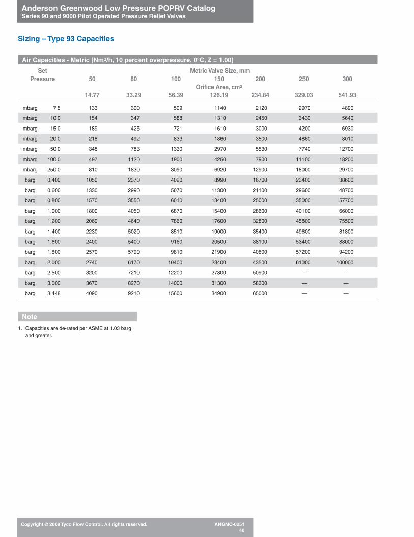
Anderson Greenwood Low Pressure POPRV CatalogSeries 90 and 9000 Pilot Operated Pressure Relief Valves
Copyright © 2008 Tyco Flow Control. All rights reserved. ANGMC-025140
Air Capacities - Metric [Nm3/h, 10 percent overpressure, 0°C, Z = 1.00]
Set Metric Valve Size, mmPressure 50 80 100 150 200 250 300
Orifice Area, cm2
14.77 33.29 56.39 126.19 234.84 329.03 541.93
mbarg 7.5 133 300 509 1140 2120 2970 4890
mbarg 10.0 154 347 588 1310 2450 3430 5640
mbarg 15.0 189 425 721 1610 3000 4200 6930
mbarg 20.0 218 492 833 1860 3500 4860 8010
mbarg 50.0 348 783 1330 2970 5530 7740 12700
mbarg 100.0 497 1120 1900 4250 7900 11100 18200
mbarg 250.0 810 1830 3090 6920 12900 18000 29700
barg 0.400 1050 2370 4020 8990 16700 23400 38600
barg 0.600 1330 2990 5070 11300 21100 29600 48700
barg 0.800 1570 3550 6010 13400 25000 35000 57700
barg 1.000 1800 4050 6870 15400 28600 40100 66000
barg 1.200 2060 4640 7860 17600 32800 45800 75500
barg 1.400 2230 5020 8510 19000 35400 49600 81800
barg 1.600 2400 5400 9160 20500 38100 53400 88000
barg 1.800 2570 5790 9810 21900 40800 57200 94200
barg 2.000 2740 6170 10400 23400 43500 61000 100000
barg 2.500 3200 7210 12200 27300 50900 — —
barg 3.000 3670 8270 14000 31300 58300 — —
barg 3.448 4090 9210 15600 34900 65000 — —
Note
1. Capacities are de-rated per ASME at 1.03 bargand greater.
Sizing – Type 93 Capacities

Anderson Greenwood Low Pressure POPRV CatalogSeries 90 and 9000 Pilot Operated Pressure Relief Valves
Copyright © 2008 Tyco Flow Control. All rights reserved. ANGMC-025141
Natural Gas Capacities (SCFM, 10 percent overpressure, 60°F, Z = 1.00 SG = 0.60)
Set Valve Size, inPressure 2 3 4 6 8 10 12
Orifice Area, in2
2.29 5.16 8.74 19.56 36.40 51.00 84.00
wc 3.0 104 234 396 886 1650 2310 3800
wc 5.0 134 302 511 1140 2130 2890 4920
wc 10.0 190 428 725 1620 3020 4230 6970
wc 15.0 233 525 890 1990 3710 5190 8550
wc 20.0 270 608 1030 2300 4290 6010 9900
wc 25.0 302 681 1150 2580 4810 6730 11100
psig 1.0 319 718 1220 2720 5070 7100 11700
psig 1.5 393 885 1500 3350 6240 8740 14400
psig 2.5 513 1150 1960 4380 8150 11400 18800
psig 5.0 742 1670 2830 6340 11800 16500 27200
psig 8.0 962 2170 3670 8220 15300 21400 35300
psig 10.0 1090 2460 4160 9310 17300 24300 40000
psig 14.0 1320 3000 5040 11300 21000 29400 48500
psig 15.0 1450 3300 5520 12400 22300 32200 53100
psig 20.0 1670 3760 6370 14200 26500 37100 61200
psig 25.0 1890 4260 7210 16100 30000 42100 69300
psig 30.0 2110 4750 8050 18000 33500 47000 77400
psig 35.0 2350 5300 9000 20000 37400 — —
psig 40.0 2600 5850 9910 22200 41300 — —
psig 45.0 2840 6400 10800 24300 45100 — —
psig 50.0 3080 6950 11800 26300 49000 — —
Note
1. Capacities are de-rated per ASME at 15 psig andgreater.
Sizing – Type 93 Capacities National Board Certified, 15 psig and greater

Anderson Greenwood Low Pressure POPRV CatalogSeries 90 and 9000 Pilot Operated Pressure Relief Valves
Copyright © 2008 Tyco Flow Control. All rights reserved. ANGMC-025142
Natural Gas Capacities - Metric [Nm3/h, 10 percent overpressure, 0°C, Z = 1.00]
Set Metric Valve Size, mmPressure 50 80 100 150 200 250 300
Orifice Area, cm2
14.77 33.29 56.39 126.19 234.84 329.03 541.93
mbarg 7.5 172 387 656 1470 2730 3830 6300
mbarg 10.0 198 447 758 1700 3160 4420 7280
mbarg 15.0 243 548 929 2080 3870 5420 8930
mbarg 20.0 281 634 1070 2400 4470 6264 10300
mbarg 50.0 447 1010 1710 3820 7110 9960 16400
mbarg 100.0 638 1440 2430 5450 10100 14200 23400
mbarg 250.0 1030 2320 3940 8810 16400 23000 37800
barg 0.400 1330 3000 5080 11400 21200 29600 48800
barg 0.600 1670 3760 6360 14200 26500 37100 61100
barg 0.800 1960 4420 7490 16700 31200 43700 71944
barg 1.000 2230 5020 8510 19000 35400 49400 81700
barg 1.200 2570 5780 9800 21900 40800 57200 94200
barg 1.400 2780 6260 10600 23700 44200 61900 102000
barg 1.600 2990 6740 11400 25500 47500 66600 110000
barg 1.800 3200 7220 12200 27400 50900 71300 117000
barg 2.000 3400 7700 13000 29200 54300 76100 125000
barg 2.500 3990 9000 15200 34100 63500 — —
barg 3.000 4570 10300 17500 39100 72700 — —
barg 3.448 5100 11500 19500 43500 81000 — —
Note
1. Capacities are de-rated per ASME at 1.03 bargand greater.
Sizing – Type 93 Capacities

Anderson Greenwood Low Pressure POPRV CatalogSeries 90 and 9000 Pilot Operated Pressure Relief Valves
Copyright © 2008 Tyco Flow Control. All rights reserved. ANGMC-025143
Air Capacities (SCFM, 10 percent overpressure, 60°F, Z = 1.00)
Set Valve Size, inPressure 2 3 4 6 8 10 12
Orifice Area, in2
2.92 6.24 10.33 22.22 39.57 56.50 89.87
wc 15.0 224 478 792 1700 3030 4330 6890
wc 20.0 259 554 917 1970 3510 5020 7980
wc 25.0 291 622 1030 2210 3940 5630 8950
psig 1.0 307 655 1080 2330 4160 5930 9440
psig 1.5 379 810 1340 2880 5130 7330 11700
psig 2.5 497 1060 1760 3780 6730 9610 15300
psig 5.0 728 1550 2570 5540 9860 14100 22400
psig 8.0 954 2040 3370 7260 12900 18500 29400
psig 10.0 1090 2330 3850 8280 14700 21100 33500
psig 15.0 1350 2880 4770 10300 18300 26100 41500
psig 20.0 1554 3320 5500 11800 21100 30100 47800
psig 25.0 1760 3760 6230 13400 23800 34000 54200
psig 30.0 1970 4200 6950 15000 26600 38000 60500
psig 35.0 2190 4690 7760 16700 29700 42400 67500
psig 40.0 2420 5170 8560 18400 32800 46800 74500
psig 45.0 2650 5650 9360 20100 35900 51200 81400
psig 50.0 2870 6140 10200 21900 38900 55600 88400
Note
1. Capacities are de-rated per ASME at 15 psig andgreater.
Sizing – Types 91 and 94 Capacities National Board Certified, 15 psig and greater

Anderson Greenwood Low Pressure POPRV CatalogSeries 90 and 9000 Pilot Operated Pressure Relief Valves
Copyright © 2008 Tyco Flow Control. All rights reserved. ANGMC-025144
Air Capacities - Metric [Nm3/h, 10 percent overpressure, 0°C, Z = 1.00]
Set Metric Valve Size, mmPressure 50 80 100 150 200 250 300
Orifice Area, cm2
18.84 40.26 66.65 143.35 255.29 364.52 579.81
mbarg 7.5 165 352 582 1250 2230 3190 5070
mbarg 35.0 358 766 1270 2730 4850 6930 11000
mbarg 55.0 451 965 1600 3430 6120 8730 13900
mbarg 70.0 511 1090 1810 3890 6920 9890 15700
mbarg 100.0 615 1310 2180 4680 8340 11900 18900
mbarg 250.0 1010 2150 3560 7650 13600 19500 30900
barg 0.400 1310 2800 4630 9960 17700 25300 40300
barg 0.600 1660 3540 5860 12600 22400 32100 51000
barg 0.800 1970 4200 6960 15000 26700 38100 60600
barg 1.000 2250 4820 7980 17200 30600 43600 69400
barg 1.200 2390 5110 8460 18200 32400 46300 73600
barg 1.400 2590 5530 9160 19700 35100 50100 79700
barg 1.600 2790 5960 9860 21200 37800 53900 85800
barg 1.800 2980 6380 10600 22700 40400 57800 91900
barg 2.000 3180 6800 11300 24200 43100 61600 98000
barg 2.500 3720 7950 13200 28300 50400 72000 114000
barg 3.000 4260 9110 15100 32400 57800 82500 131000
barg 3.448 4750 10100 16800 36100 64400 92000 146000
Note
1. Capacities are de-rated per ASME at 1.03barg and greater.
Sizing – Types 91 and 94 Capacities

Anderson Greenwood Low Pressure POPRV CatalogSeries 90 and 9000 Pilot Operated Pressure Relief Valves
Copyright © 2008 Tyco Flow Control. All rights reserved. ANGMC-025145
Sizing – Type 95 Capacities National Board Certified, 15 psig and greater
Air Capacities (SCFM, 10 percent overpressure, 60°F, Z = 1.00)
Set Valve Size, inPressure 2 3 4 6
Orifice Area, in2
2.93 6.25 10.32 22.15
psig 5.0 — 1560 2570 5520
psig 10.0 1090 2330 3850 8260
psig 15.0 1500 3190 5270 11300
psig 20.0 1720 3680 6080 13000
psig 40.0 2690 5730 9460 20300
psig 60.0 3690 7880 13000 27900
psig 80.0 4700 10000 16500 35500
psig 100.0 5710 12300 20100 43100
psig 120.0 6710 14300 23600 50700
psig 140.0 7720 16500 27200 58400
psig 150.0 8220 17500 29000 62200
Air Capacities - Metric [Nm3/h,10 percent overpressure,0°C, Z=1.00]
Set Metric Valve Size, mmPressure 50 80 100 150
Orifice Area, cm2
18.90 40.32 66.58 142.90
barg 0.250 — 2150 3550 7630
barg 0.400 — 2800 4630 9930
barg 0.600 — 3550 5860 12600
barg 0.800 1970 4210 6960 14900
barg 1.000 2260 4830 7970 17100
barg 1.500 2980 6370 10500 22600
barg 2.000 3520 7520 12400 26700
barg 2.500 4130 8810 14500 31200
barg 3.000 4730 10100 16700 35800
barg 4.000 5940 12700 20900 44900
barg 5.000 7150 15200 25200 54000
barg 7.000 9560 20400 33700 72300
barg 10.000 13200 28100 46400 99600
Note
1. Capacities are de-rated per ASME at 15 psigand greater (1.03 barg and greater).

Anderson Greenwood Low Pressure POPRV CatalogSeries 90 and 9000 Pilot Operated Pressure Relief Valves
Copyright © 2008 Tyco Flow Control. All rights reserved. ANGMC-025146
Air Capacity (SCFM, 10 percent overpressure at 60°F)
Set Valve Size, inPressure 2 3 4 6 8 10 12
Orifice Area, in2
3.35 7.39 12.73 28.89 50.00 78.85 113.00
wc 4 133 294 506 1150 1990 3130 4490
wc 6 167 367 632 1430 2490 3920 5620
wc 8 196 430 741 1680 2910 4590 6580
wc 10 221 486 838 1900 3290 5190 7440
wc 15 277 608 1050 2380 4120 6490 9310
wc 20 324 712 1230 2780 4820 7600 10900
wc 25 366 805 1390 3150 5450 8590 12300
psig 1.0 387 852 1470 3330 5770 9090 13000
psig 1.5 484 1060 1830 4160 7200 11400 16300
psig 2.0 566 1250 2150 4870 8430 13300 19100
psig 2.5 640 1410 2420 5500 9530 15000 21500
psig 3.0 706 1550 2680 6070 10500 16600 23800
psig 4.0 826 1820 3130 7100 12300 19400 27800
psig 5.0 932 2050 3530 8010 13900 21900 31400
Air Capacity - Metric [Nm3/h, 10 percent overpressure at 0°C]
Set Metric Valve Size, mmPressure 50 80 100 150 200 250 300
Orifice Area, cm2
21.61 47.68 82.13 186.39 322.58 508.71 729.03
mbarg 10 221 487 838 1900 3290 5190 7450
mbarg 15 277 608 1050 2380 4120 6490 9310
mbarg 20 324 713 1230 2790 4830 7610 10911
mbarg 25 367 806 1390 3150 5460 8600 12300
mbarg 40 475 1040 1800 4080 7070 11100 16000
mbarg 50 537 1180 2030 4610 7990 12600 18100
mbarg 60 593 1300 2250 5100 8830 13900 20000
mbarg 70 646 1420 2450 5550 9610 15100 21700
barg 0.1 785 1730 2970 6750 11700 18400 26400
barg 0.15 980 2160 3710 8430 14600 23000 33000
barg 0.2 1150 2520 4340 9860 17100 26900 38600
barg 0.3 1430 3140 5410 12300 21300 33500 48100
barg 0.35 1550 3410 5880 13300 23100 36400 52300
Sizing – 9200 Capacities
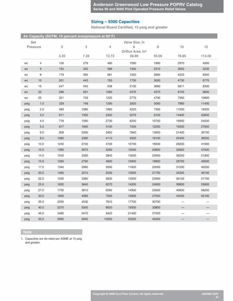
Anderson Greenwood Low Pressure POPRV CatalogSeries 90 and 9000 Pilot Operated Pressure Relief Valves
Copyright © 2008 Tyco Flow Control. All rights reserved. ANGMC-025147
Air Capacity (SCFM, 10 percent overpressure at 60°F)
Set Valve Size, inPressure 2 3 4 6 8 10 12
Orifice Area, in2
3.35 7.39 12.73 28.89 50.00 78.85 113.00
wc 4 126 279 480 1090 1890 2970 4260
wc 6 155 342 589 1340 2310 3650 5230
wc 8 179 395 681 1550 2680 4220 6050
wc 10 201 443 763 1730 3000 4730 6770
wc 15 247 545 938 2130 3680 5811 8330
wc 20 286 631 1090 2470 4270 6740 9600
wc 25 321 709 1220 2770 4790 7560 10800
psig 1.0 339 748 1290 2920 5060 7980 11400
psig 2.0 489 1080 1860 4220 7300 11500 16500
psig 3.0 611 1350 2320 5270 9120 14400 20600
psig 4.0 718 1580 2730 6200 10700 16900 24200
psig 5.0 817 1800 3100 7050 12200 19200 27600
psig 6.0 909 2000 3450 7840 13600 21400 30700
psig 8.0 1080 2380 4110 9320 16100 25400 36500
psig 10.0 1240 2740 4720 10700 18500 29200 41900
psig 12.0 1390 3070 5290 12000 20800 32800 47000
psig 14.0 1540 3390 5840 13200 22900 36200 51800
psig 15.0 1260 2790 4800 10900 18800 29700 42600
psig 17.0 1340 2960 5090 11600 20000 31500 45200
psig 20.0 1460 3210 5530 12600 21700 34300 49100
psig 22.0 1530 3380 5830 13200 22900 36100 51700
psig 25.0 1650 3640 6270 14200 24600 38800 55600
psig 27.0 1730 3810 6560 14900 25600 40600 58200
psig 30.0 1840 4060 7000 15900 27500 43400 62100
psig 35.0 2050 4530 7810 17700 30700 — —
psig 40.0 2270 5000 8620 19500 33800 — —
psig 45.0 2480 5470 9420 21400 37000 — —
psig 50.0 2690 5940 10200 23200 40200 — —
Note
1. Capacities are de-rated per ASME at 15 psigand greater.
Sizing – 9300 CapacitiesNational Board Certified, 15 psig and greater
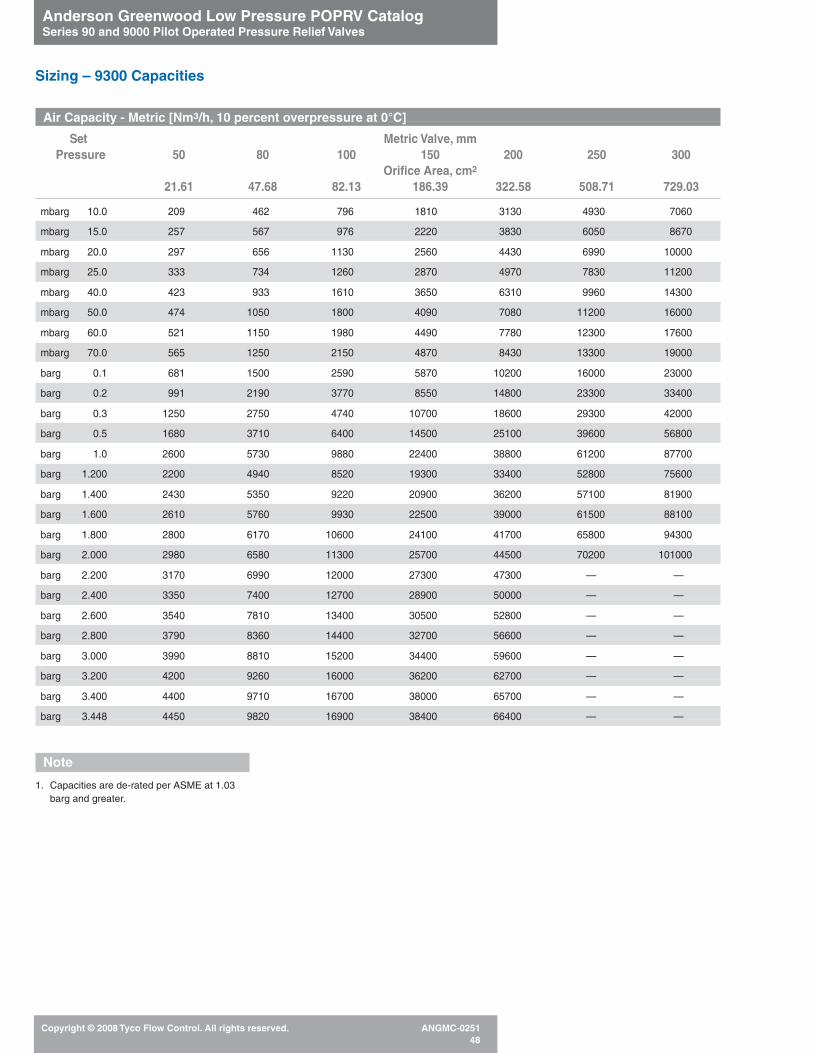
Anderson Greenwood Low Pressure POPRV CatalogSeries 90 and 9000 Pilot Operated Pressure Relief Valves
Copyright © 2008 Tyco Flow Control. All rights reserved. ANGMC-025148
Air Capacity - Metric [Nm3/h, 10 percent overpressure at 0°C]
Set Metric Valve, mmPressure 50 80 100 150 200 250 300
Orifice Area, cm2
21.61 47.68 82.13 186.39 322.58 508.71 729.03
mbarg 10.0 209 462 796 1810 3130 4930 7060
mbarg 15.0 257 567 976 2220 3830 6050 8670
mbarg 20.0 297 656 1130 2560 4430 6990 10000
mbarg 25.0 333 734 1260 2870 4970 7830 11200
mbarg 40.0 423 933 1610 3650 6310 9960 14300
mbarg 50.0 474 1050 1800 4090 7080 11200 16000
mbarg 60.0 521 1150 1980 4490 7780 12300 17600
mbarg 70.0 565 1250 2150 4870 8430 13300 19000
barg 0.1 681 1500 2590 5870 10200 16000 23000
barg 0.2 991 2190 3770 8550 14800 23300 33400
barg 0.3 1250 2750 4740 10700 18600 29300 42000
barg 0.5 1680 3710 6400 14500 25100 39600 56800
barg 1.0 2600 5730 9880 22400 38800 61200 87700
barg 1.200 2200 4940 8520 19300 33400 52800 75600
barg 1.400 2430 5350 9220 20900 36200 57100 81900
barg 1.600 2610 5760 9930 22500 39000 61500 88100
barg 1.800 2800 6170 10600 24100 41700 65800 94300
barg 2.000 2980 6580 11300 25700 44500 70200 101000
barg 2.200 3170 6990 12000 27300 47300 — —
barg 2.400 3350 7400 12700 28900 50000 — —
barg 2.600 3540 7810 13400 30500 52800 — —
barg 2.800 3790 8360 14400 32700 56600 — —
barg 3.000 3990 8810 15200 34400 59600 — —
barg 3.200 4200 9260 16000 36200 62700 — —
barg 3.400 4400 9710 16700 38000 65700 — —
barg 3.448 4450 9820 16900 38400 66400 — —
Note
1. Capacities are de-rated per ASME at 1.03barg and greater.
Sizing – 9300 Capacities

Anderson Greenwood Low Pressure POPRV CatalogSeries 90 and 9000 Pilot Operated Pressure Relief Valves
Copyright © 2008 Tyco Flow Control. All rights reserved. ANGMC-025149
Sizing – Type 96A Vacuum Capacities
Air Capacities (SCFH, 60°F, Z = 1.00)
Full Open1 Valve Size, inVacuum Relief 4 6 8 12
(oz/in2) Orifice Area, in2
11.70 23.89 38.60 80.93
1.0 19400 43800 84600 199000
3.0 31200 84600 147000 321000
Air Capacities - Metric [Nm3/h, 0°C, Z = 1.00]
Full Open1 Metric Valve Size, mmVacuum Relief 100 150 200 300
[mbarg] Orifice Area, cm2
75.49 154.13 249.03 522.13
4.3 536 1210 2330 5470
12.9 860 2330 4050 8850
Sizing – Type 9200/9300 Vacuum Capacities
Vacuum Capacity - @ 1 oz. in2 [4.3 mb] - SCFH , 60°F [Nm3/h, 0°C]1
Valve Size 9200 9300
2-inch [50 mm] 4850 [134] 4000 [110]
3-inch [80 mm] 10700 [295] 8830 [243]
4-inch [100 mm] 18400 [508] 15200 [419]
6-inch [150 mm] 41800 [1150] 34500 [951]
8-inch [200 mm] 72400 [2000] 59700 [1650]
10-inch [250 mm] 114000 [3150] 94200 [2600]
12-inch [300 mm] 164000 [4510] 135000 [3720]
Note
1. Nameplate vacuum setting 1/2 full open vacuum. Capacities based on flow testing.

Anderson Greenwood Low Pressure POPRV CatalogSeries 90 and 9000 Pilot Operated Pressure Relief Valves
Copyright © 2008 Tyco Flow Control. All rights reserved. ANGMC-025150
12"
8"
6"
4"
1.0 [4.3] 2.0 [8.6] 3.0 [12.9] 4.0 [17.2] 5.0 [21.5] 6.0 [25.8] 7.0 [30.1]0
10,000[268]
100,000[2680]
1,000,000[26,800]
Vacuum, oz/in2 [mbarg]
Flo
w,S
CF
H[N
m3 /
h]
1/2 oz[2.2]
11/2 oz[6.5]
Type 96A Flow Test Results
Note
Sizing program not applicable for Type 96A.
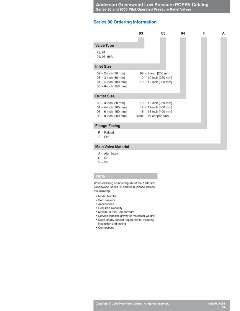
Anderson Greenwood Low Pressure POPRV CatalogSeries 90 and 9000 Pilot Operated Pressure Relief Valves
Copyright © 2008 Tyco Flow Control. All rights reserved. ANGMC-025151
Valve Type
93, 91,94, 95, 96A
Inlet Size
02 – 2-inch [50 mm] 08 – 8-inch [200 mm]03 – 3-inch [80 mm] 10 – 10-inch [250 mm]04 – 4-inch [100 mm] 12 – 12-inch [300 mm]06 – 6-inch [150 mm]
Outlet Size
03 – 3-inch [80 mm] 10 – 10-inch [250 mm]04 – 4-inch [100 mm] 12 – 12-inch [300 mm]06 – 6-inch [150 mm] 16 – 16-inch [400 mm]08 – 8-inch [200 mm] Blank – for capped 96A
Flange Facing
R – RaisedF – Flat
Main Valve Material
A – AluminumC – CSS – SS
Series 90 Ordering Information
93 03 04 F A
Note
When ordering or inquiring about the AndersonGreenwood Series 90 and 9000, please includethe following:
• Model Number• Set Pressure• Accessories• Required Capacity• Maximum Inlet Temperature• Service (specific gravity or molecular weight)• Detail of any special requirements, including
inspection and testing• Connections
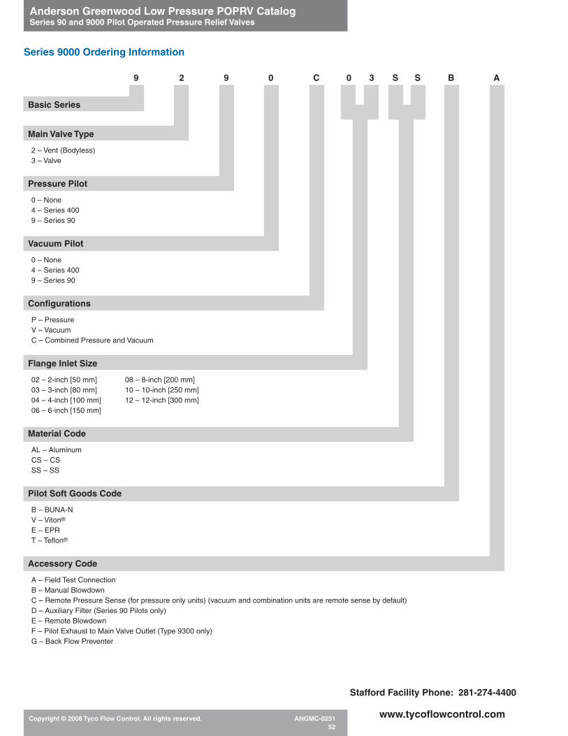
Anderson Greenwood Low Pressure POPRV CatalogSeries 90 and 9000 Pilot Operated Pressure Relief Valves
Copyright © 2008 Tyco Flow Control. All rights reserved. ANGMC-025152
www.tycoflowcontrol.com
Basic Series
Main Valve Type
2 – Vent (Bodyless)3 – Valve
Pressure Pilot
0 – None4 – Series 4009 – Series 90
Vacuum Pilot
0 – None4 – Series 4009 – Series 90
Configurations
P – PressureV – VacuumC – Combined Pressure and Vacuum
Flange Inlet Size
02 – 2-inch [50 mm] 08 – 8-inch [200 mm]03 – 3-inch [80 mm] 10 – 10-inch [250 mm]04 – 4-inch [100 mm] 12 – 12-inch [300 mm]06 – 6-inch [150 mm]
Material Code
AL – AluminumCS – CSSS – SS
Pilot Soft Goods Code
B – BUNA-NV – Viton®
E – EPRT – Teflon®
Accessory Code
A – Field Test ConnectionB – Manual BlowdownC – Remote Pressure Sense (for pressure only units) (vacuum and combination units are remote sense by default)D – Auxiliary Filter (Series 90 Pilots only)E – Remote BlowdownF – Pilot Exhaust to Main Valve Outlet (Type 9300 only)G – Back Flow Preventer
Series 9000 Ordering Information
9 2 9 0 C 0 3 S S B A
Stafford Facility Phone: 281-274-4400