andrew - americanradiohistory.comamericanradiohistory.com/.../andrew-catalog-26-1969.pdfandrew is a...
TRANSCRIPT

110
ANDREW catalog 26 antennas 'transmission lines

SALES OFFICES
CHICAGO Andrew Corporation 10500 W. 153rd St. Orland Park, Illinois, U.S.A. 60462 Telephone: (312) 349-3300 TWX: 910-651-3340, Telex: 25-3897 Cable: WERDNA, Chicago
NEW YORK Andrew Corporation P. 0. Box 416 Ridgewood, New Jersey, U.S.A. 07451 Phone: (201) 445-2500, Telex: 13-3336
WASHINGTON, D.C. Andrew Corporation P. 0. Box 1470 Rockville, Maryland, U.S.A. 20850 Phone: (301) 762-1900, Telex: 8-9688
DENVER Andrew Corporation 1745 Denver Merchandise Mart 451 E. 58th Avenue Denver, Colorado, U.S.A. 80216 Phone: (303) 222-1579, Telex: 45-732
DALLAS Andrew Corporation P. 0. Box 938 Richardson, Texas, U.S.A. 75080 Phone: (214) 235-1279, Telex: 73-2391
LOS ANGELES Andrew California Corporation 615 N. Euclid Ave., Room 111 Ontario, California, U.S.A. 91761 Phone: (714) 986-1121, Telex: 67-4377
Andrew California Corporation (Plant only) 941 E. Marylind Avenue Claremont, California, U.S.A. 91711 Phone: (714) 626-3505, Telex: 67-0426
ORLAND PARK, ILLINOIS
AND PLANTS
SAN FRANCISCO Andrew California Corporation 701 Welch Road Palo Alto, California, U.S.A. 94304 Phone: (415) 323-3139, Telex: 34-8447
SEATTLE Andrew Corporation 11520 Lake City Way, N.E. Seattle, Washington, U.S.A. 98125 Phone: (206) 362- 5335
TORONTO Andrew Antenna Company Ltd. 606 Beech Street Whitby, Ontario, Canada Phone: (416) 668-3348, Telex: 02-29562 TWX: 610-384-2751, Cable: ANDCORP, Whitby
MONTREAL Andrew Antenna Company Ltd. 130 Berkley Avenue St. Lambert, Quebec, Canada Phone: (514) 672-5833, Telex: 01-26467
VANCOUVER Andrew Antenna Company Ltd. 422 - 6th Street New Westminster, B.C., Canada Phone: (604) 526-4271, Telex: 043-5211
EDINBURGH* Andrew Antenna Systems Lochgelly, Fife, Great Britain Phone: (059-278) 561 Telex: 72491, Cable: WERDNA, Edinburgh
MELBOURNE* Andrew Antennas Division of Andrew Corporation 171 Henty St., Reservoir, Victoria, Australia 3073 Phone: 460-1544, 46-4178, Telex: 30840 Cable: ANDANT, Melbourne
Copyright 1969 by Andrew Corporation *Indicates Office and Plant Other countries, see page 96

Andrew is a highly specialized company, concentrating on an-
tennas, RF transmission lines, and related items comprising an
antenna system. Our chosen field of specialization is narrow, but we cover it in depth.
Although we serve a technically dynamic industry, we know
that nobody wants an experimental model of an antenna, co-
axial cable, or waveguide. These are hardware items. They
must perform their functions effectively and reliably, and with
modest skill requirements for installation. That is why, when
you order from Andrew, you get equipment that has been
thoroughly debugged, and which fulfills the performance claims stated in this catalog.
Most of this catalog is devoted to our standard product line of
antennas, cables, waveguides, and related items. Not describ- ed, but playing a vital role in the historic growth of Andrew, is our proficiency in performing special contracts in the anten-
na systems field.
The resources we can bring to bear on such programs-in- cluding system and product engineering, program management, manufacturing, quality control, contract administration, finance, and field service-are evenly balanced for effective contract performance, and in their totality represent a combination of
skills and capabilities that is unique in the electronics industry.
TABLE OF CONTENTS
SECTION PAGE
MICROWAVE ANTENNAS 2
LARGE ANTENNAS 21
MICROWAVE WAVEGUIDES 22
TELEMETRY ANTENNAS 34
TRANSPORTABLE MASTS 38
ANTENNA POSITIONERS 40
FIXED STATION ANTENNAS 44
SOLID DIELECTRIC CABLES 51
HELIAX FLEXIBLE COAXIAL CABLES 52
RIGID COAXIAL TRANSMISSION LINES 74
COAXIAL SWITCHING EQUIPMENT 78
PRESSURIZATION EQUIPMENT 81
COAXIAL CABLE DATA 86
AIV®REVi!
MICROWAVE ANTENNAS GUARANTEED ELECTRICAL CHARACTERISTICS.
The following terms are used to describe the guar- anteed characteristics of Andrew antennas.
Frequency refers to the operating frequency band. These bands correspond to CCIR recommendations or common allocations used in the United States or Canada. It is usually practical to tune antenna feeds for slightly different frequency ranges while retain- ing the same electrical characteristics. Should your requirements cover other ranges, they can be ac- commodated on special order.
Gain is given in dBi (decibels over an isotropic radi- ator) at three frequencies: bottom of band, mid - band and top of band.
Front -to -Back Ratio in decibels denotes highest ra- diation relative to the main beam at 180° ± 5°, across the band. For high performance shielded an- tennas, the ratio refers to the region 180° ± 80°.
VSWR, maximum, is the peak value over the entire operating band. For the conversion table of VSWR versus return loss and reflection coefficient, see page 18.
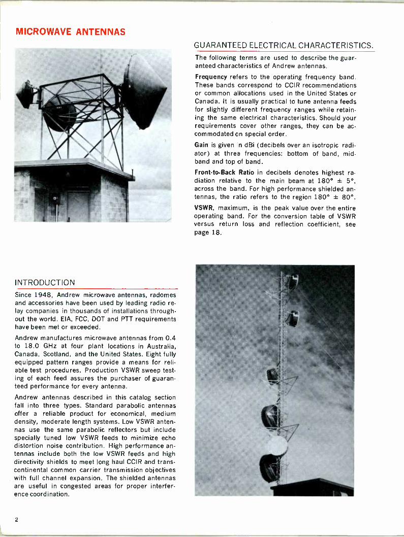
INTRODUCTION
Since 1948, Andrew microwave antennas, radomes and accessories have been used by leading radio re- lay companies in thousands of installations through- out the world. EIA, FCC, DOT and PTT requirements have been met or exceeded.
Andrew manufactures microwave antennas from 0.4 to 18.0 GHz at four plant locations in Australia, Canada, Scotland, and the United States. Eight fully equipped pattern ranges provide a means for reli- able test procedures. Production VSWR sweep test- ing of each feed assures the purchaser of guaran- teed performance for every antenna.
Andrew antennas described in this catalog section fall into three types. Standard parabolic antennas offer a reliable product for economical, medium density, moderate length systems. Low VSWR anten- nas use the same parabolic reflectors but include specially tuned low VSWR feeds to minimize echo distortion noise contribution. High performance an- tennas include both the low VSWR feeds and high directivity shields to meet long haul CCIR and trans- continental common carrier transmission objectives with full channel expansion. The shielded antennas are useful in congested areas for proper interfer- ence coordination.
2

MICROWAVE ANTENNAS
Half Power Beamwidth is the width of the main beam to the -3 dB points on either side and may
be found from the graph on page 18 using the antenna gain.
Cross Polarization Discrimination exceeds 25 dB for all antennas listed.
Isolation. All dual polarized designs feature isola-
tion between inputs of at least 35 dB, unless other- wise noted.
Pressurization. All feeds are pressure tight to 10
psig, unless otherwise noted.
Input Flange types per U.S. EIA or MIL standards are stated for each antenna series. A table of wave - guide and flange nomenclature listing IEC stand- ards is shown on page 27. Special flange types are available on special order.
Radiation Pattern Envelopes for all antennas listed are on file with the U.S. FCC, Canadian DOT and
microwave radio equipment manufacturers. These are available on request to assist in your system planning. See Page 19 for more information.
The radiation pattern envelope, or RPE is gener- ated by measuring radiation patterns of each an- tenna type at the low end, middle and high end of
the operating band. These patterns are folded around the main beam and superimposed on a
common grid. The "Typical" RPE is drawn as the smooth pattern near which most patterns fall. The
"Guaranteed" RPE is drawn as the smooth pattern below which all measured patterns fall.
Your application may be served by catalog designs or modifications thereof. Andrew sales engineers will be pleased to review your specific requirements.
450 AND 890 MHz MICROWAVE ANTENNAS
Plane polarized.
Coaxial dipole primary radiators.
Continuous polarization adjustment.
7/8" EIA 50 ohm flange input.
Antenna mounts are listed on pages 11-13.
7/8" and 1-5/8" HELIAX coaxial cable feed lines are shown on pages 64-67.
GUARANTEED ELECTRICAL CHARACTERISTICS
Frequency MHz
Type Number
Diameter Feet
Gain, dBi Bottom Mid Band Top
Front -to -Back Ratio,dB
VSWR Maximum
450-470 P6-4 6 15.2 15.5 15.8 20 1.3 P10-4 10 19.9 20.2 20.5 25 1.3
P4-9 4 18.6 19.0 19.4 27 1.3 890-960 P6-9 6 21.6 22.0 22.4 30 1.3
P10-9 10 26.4 26.8 27.2 37 1.3
ANDREW 3

2 GHz MICROWAVE ANTENNAS
Plane Polarized
Plane Polarized -Standard and Low VSWR
Broadband coaxial horn radiator. 7/8" EIA 50 ohm input flange. Continuous polarization adjustment. Pressure tight to 5 psig. Average power rating, 100 watts.
Dual Polarized -Low VSWR
7/8" EIA 50 ohm input flanges. Other Frequency bands available.
Accessories And Feed Lines
Radomes are listed on page 10. Antenna mounts are listed on pages 11-13.
7/8" and 1-5/8" HELIAX coaxial cable and fittings are listed on pages 64-67. Type EW17 HELIAX elliptical waveguide and fittings are described on pages 22-29.
GUARANTEED ELECTRICAL CHARACTERISTICS
Frequency, GHz and Type
Type Number
Diameter Feet
Gain, dBi Bottom Mid Band Top
Front -to -Back Ratio, dB
VSWR Maximum
1.7 -1.85 P4-17 4 23.8 24.2 24.6 29 1.3 Plane P6-17 6 27.6 28.0 28.4 35 1.3 Polarized P10 -17A 10 31.9 32.3 32.7 43 1.1
1.85.2.11 P4-18 4 24.8 25.4 26.0 31 1.3 Plane P6-18 6 28.4 29.0 29.6 36 1.3 Polarized P10 -18A 10 32.8 33.4 34.0 44 1.1
2.11 - 2.3 P4-21 4 26.1 26.5 26.9 34 1.3 Plane P6-21 6 29.6 30.0 30.4 36 1.3 Polarized P10-21 10 34.1 34.5 34.9 45 1.1
1.7 - 2.1 PL6-17 6 27.6 28.5 29.4 35 1.10 Plane PL8-17 8 30.1 31.0 31.9 38 1.06 Polarized PL10-17 10 32.1 33.0 33.9 43 1.06 Low VSWR PL12-17 12 33.6 34.5 35.4 44 1.06
KL15-17 15 35.5 36.4 37.3 46 1.06
1.9-2.3 P16-19 6 28.4 29.3 30.2 36 1.10 Plane PL8-19 8 30.9 31.8 32.7 39 1.06 Polarized PL10-19 10 32.8 33.7 34.6 44 L06 Low VSWR PL12-19 12 34.4 35.3 36.2 47 L06
KL15.19 15 36.3 37.2 38.1 49 L06
1.9 - 2.3 70749 10 32.9 33.7 34.5 43 1.08 Dual 70750 12 34.5 35.3 36.1 44 1.08 Polarized 70751 15 36.3 37.1 37.9 46 1.08 Low VSWR
2.45 - 2.7 P4-24 4 27.3 27.7 28.1 34 1.3 Plane P6-24 6 30.8 31.2 31.6 38 1.3 Polarized P10-24 10 35.4 35.8 36.2 42 1.2
4
4 AND 5 GHz MICROWAVE ANTENNAS
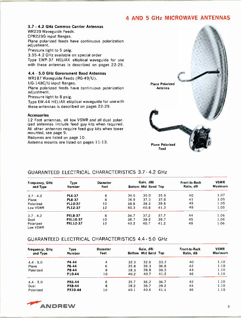
3.7 - 4.2 GHz Common Carrier Antennas WR229 Waveguide Feeds. CPR229G input flanges. Plane polarized feeds have continuous polarization adjustment. Pressure tight to 5 psig. 3.55-4.2 GHz available on special order Type EWP-37 HELIAX elliptical waveguide for use with these antennas is described on pages 22-29.
4.4 - 5.0 GHz Government Band Antennas WR187 Waveguide Feeds (RG -49/U). UG-148C/U input flanges. Plane polarized feeds have continuous polarization adjustment. Pressure tight to 8 psig. Type EW-44 HELIAX elliptical waveguide for use with these antennas is described on pages 22-29.
Accessories 12 Foot antennas, all low VSWR and all dual polar- ized antennas include feed guy kits when required. All other antennas require feed guy kits when tower mounted, see page 9. Radomes are listed on page 10. Antenna mounts are listed on pages 11-13.
Plane Polarized Antenna
Plane Polarized Feed
GUARANTEED ELECTRICAL CHARACTERISTICS 3.7-4.2 GHz
Frequency, GHz and Type
Type Number
Diameter Feet
Gain, dBi Bottom Mid Band Top
Front -to -Back Ratio, dB
VSWR Maximum
3.7 - 4.2 PL6-37 6 34.5 35.0 35.5 40 1.07 Plane PL8-37 8 36.8 37.3 37.8 41 1.05 Polarized PL10-37 10 38.8 39.3 39.8 45 1.05 Low VSWR PL12-37 12 40.3 40.8 41.3 48 1.05
3.7 - 4.2 PXL8-37 8 36.7 37.2 37.7 44 1.06 Dual PXL10-37 10 38.7 39-2 39.7 45 1.06 Polarized PXL12-37 12 40.2 40.7 41.2 48 1.06 Low VSWR
GUARANTEED ELECTRICAL CHARACTERISTICS 4.4- 5.0 GHz
Frequency, GHz and Type
Type Number
Diameter Feet
Gain, dBi Bottom Mid Band Top
Front -to -Back Ratio, dB
VSWR Maximum
4.4 - 5.0 P4-44 4 32.3 32.8 33.3 40 1.10 Plane P6-44 6 35.8 36.3 36.8 42 1.10 Polarized P8-44 8 38.3 38.8 39.3 44 1.10
P10-44 10 40.2 40.7 41.2 46 1.10
4.4 - 5.0 PX6-44 6 35.7 36.2 36.7 42 1.10 Dual PX8-44 8 38.2 38.7 39.2 44 1.10 Polarized PX10-44 10 40.1 40.6 41.1 46 1.10
ANDAEW 5
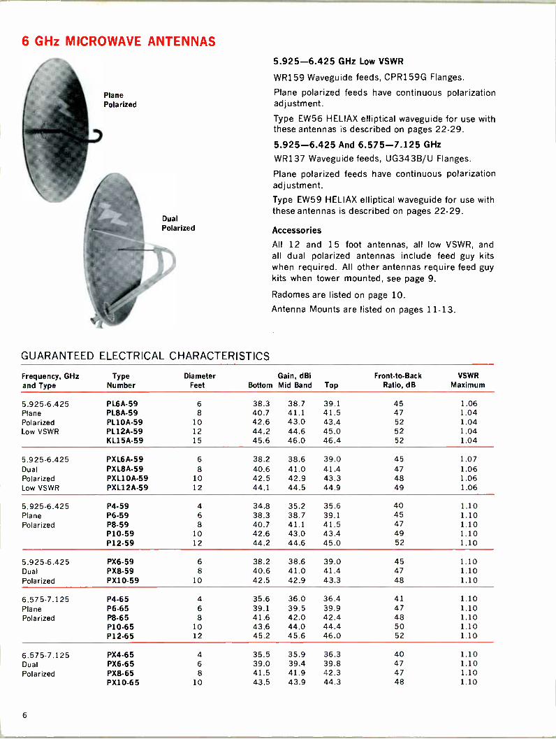
6 GHz MICROWAVE ANTENNAS
Plane Polarized
Dual Polarized
GUARANTEED ELECTRICAL CHARACTERISTICS
5.925-6.425 GHz Low VSWR
WR159 Waveguide feeds, CPR159G Flanges.
Plane polarized feeds have continuous polarization adjustment.
Type EW56 HELIAX elliptical waveguide for use with these antennas is described on pages 22-29.
5.925-6.425 And 6.575-7.125 GHz
WR137 Waveguide feeds, UG343B/U Flanges.
Plane polarized feeds have continuous polarization adjustment.
Type EW59 HELIAX elliptical waveguide for use with these antennas is described on pages 22.29.
Accessories
All 12 and 15 foot antennas, all low VSWR, and all dual polarized antennas include feed guy kits when required. All other antennas require feed guy kits when tower mounted, see page 9.
Radomes are listed on page 10.
Antenna Mounts are listed on pages 11-13.
Frequency, GHz and Type
Type Number
Diameter Feet
Gain, dBi Bottom Mid Band Top
Front -to -Back Ratio, dB
VSWR Maximum
5.925-6.425 PL6A-59 6 38.3 38.7 39.1 45 1.06 Plane PLEA -59 8 40.7 41.1 41.5 47 1.04 Polarized PL10A-59 10 42.6 43.0 43.4 52 1.04 Low VSWR PL12A-59 12 44.2 44.6 45.0 52 1.04
KL15A-59 15 45.6 46.0 46.4 52 1.04
5.925-6.425 PXL6A-59 6 38.2 38.6 39.0 45 1.07 Dual PXL8A-59 8 40.6 41.0 41.4 47 1.06 Polarized PXL10A-59 10 42.5 42.9 43.3 48 1.06 Low VSWR PXL12A-59 12 44.1 44.5 44.9 49 1.06
5.925-6.425 P4.59 4 34.8 35.2 35.6 40 1.10 Plane P6-59 6 38.3 38.7 39.1 45 1.10 Polarized P8-59 8 40.7 41.1 41.5 47 1.10
P10-59 10 42.6 43.0 43.4 49 1.10 P12-59 12 44.2 44.6 45.0 52 1.10
5.925-6.425 PX6-59 6 38.2 38.6 39.0 45 1.10 Dual PX8-59 8 40.6 41.0 41.4 47 1.10 Polarized PX10.59 10 42.5 42.9 43.3 48 1.10
6.575-7.125 P4-65 4 35.6 36.0 36.4 41 1.10 Plane P6.65 6 39.1 39.5 39.9 47 1.10 Polarized P8-65 8 41.6 42.0 42.4 48 1.10
P10-65 10 43.6 44.0 44.4 50 1.10 P12.65 12 45.2 45.6 46.0 52 1.10
6.575-7.125 PX4-65 4 35.5 35.9 36.3 40 1.10 Dual PX6-65 6 39.0 39.4 39.8 47 1.10 Polarized PX8-65 8 41.5 41.9 42.3 47 1.10
PX10-65 10 43.5 43.9 44.3 48 1.10
6
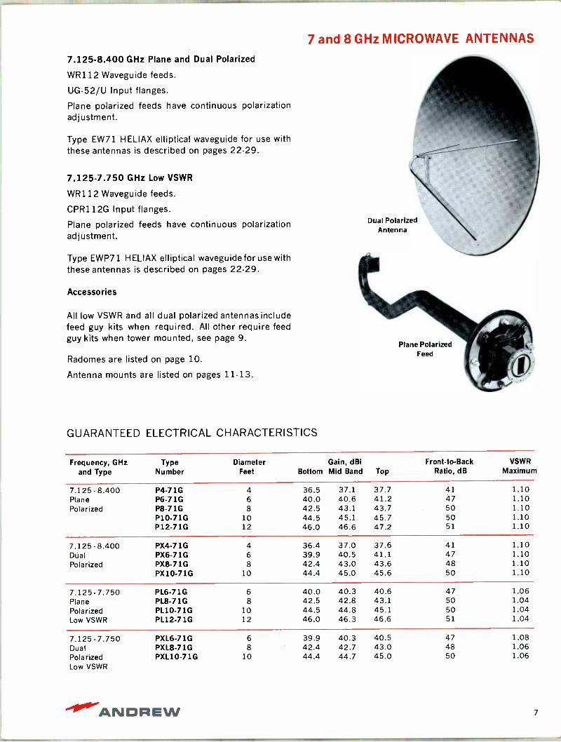
7 and 8 GHz MICROWAVE ANTENNAS
7.125-8.400 GHz Plane and Dual Polarized
WR112 Waveguide feeds.
UG-52/U Input flanges.
Plane polarized feeds have continuous polarization adjustment.
Type EW71 HELIAX elliptical waveguide for use with these antennas is described on pages 22-29.
7.125-7.750 GHz Low VSWR
WR112 Waveguide feeds.
CPR112G Input flanges.
Plane polarized feeds have continuous polarization adjustment.
Type EWP71 HELIAX elliptical waveguide for use with these antennas is described on pages 22-29.
Accessories
All low VSWR and all dual polarized antennas include feed guy kits when required. All other require feed guy kits when tower mounted, see page 9.
Radomes are listed on page 10.
Antenna mounts are listed on pages 11-13.
GUARANTEED ELECTRICAL CHARACTERISTICS
Dual Polarized Antenna
Plane Polarized Feed
Frequency, GHz and Type
Type Number
Diameter Feet
Gain, dBi Bottom Mid Band Top
Front -to -Back Ratio, dB
VSWR Maximum
7.125-8.400 P4 -71G 4 36.5 37.1 37.7 41 1.10 Plane P6 -71G 6 40.0 40.6 41.2 47 1.10 Polarized P8 -71G 8 42.5 43.1 43.7 50 1.10
P10 -71G 10 44.5 45.1 45.7 50 1.10 P12 -71G 12 46.0 46.6 47.2 51 1.10
7.125-8.400 PX4-71G 4 36.4 37.0 37.6 41 1.10 Dual PX6-71G 6 39.9 40.5 41.1 47 1.10 Polarized PX8-71G 8 42.4 43.0 43.6 48 1.10
PX10-71G 10 44.4 45.0 45.6 50 1.10
7.125-7.750 PL6-71G 6 40.0 40.3 40.6 47 1.06 Plane PL8-71G 8 42.5 42.8 43.1 50 1.04 Polarized PL10.71G 10 44.5 44.8 45.1 50 1.04 Low VSWR PL12.71G 12 46.0 46.3 46.6 51 1.04
7.125-7.750 PXL6-71G 6 39.9 40.3 40.5 47 1.08 Dual PXL8-71G 8 42.4 42.7 43.0 48 1.06 Polarized PXL10-71G 10 44.4 44.7 45.0 50 1.06 Low VSWR
"11.1.. -ANDREW 7
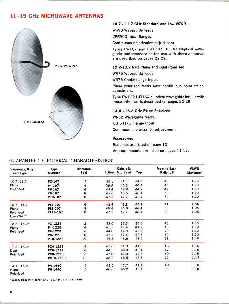
11-15 GHz MICROWAVE ANTENNAS
Plane Polarized
Dual Polarized
GUARANTEED ELECTRICAL CHARACTERISTICS
10.7 - 11.7 GHz Standard and Low VSWR
WR90 Waveguide feeds.
CPR90G Input flanges.
Continuous polarization adjustment.
Types EW107 and EWP107 HELIAX elliptical wave -
guide and accessories for use with these antennas are described on pages 22-29.
12.2-13.2 GHz Plane and Dual Polarized
WR75 Waveguide feeds.
WR75 Choke flange input.
Plane polarized feeds have continuous polarization adjustment.
Type EW122 HELIAX elliptical waveguide for use with these antennas is described on pages 22-29.
14.4 - 15.2 GHz Plane Polarized
WR62 Waveguide feeds.
UG-541/U Flange input.
Continuous polarization adjustment.
Accessories
Radomes are listed on page 10.
Antenna mounts are listed on pages 11-13.
Frequency, GHz and Type
Type Number
Diameter, Feet
Gain, dBi Bottom Mid Band Top
Front -to -Back Ratio, dB
VSWR Maximum
10.7 - 1 1.7 P2-107 2 34.1 34.5 34.9 40 1.15 Plane P4-107 4 39.9 40.3 40.7 45 1.10 Polarized P6-107 6 43.4 43.8 44.2 47 1.10
P8-107 8 45.6 46.0 46.4 50 1.10 P10-107 10 47.3 47.7 48.1 52 1.10
10.7 - 11.7 PL6-107 6 43.4 43.8 44.2 47 1.06 Plane PL8-107 8 45.6 46.0 46.4 50 1.06 Polarized PL10-107 10 47.3 47.7 48.1 52 1.06 Low VSWR
12.2 - 13.2 P2 -122B 2 35.0 35.3 35.6 40 1.15 Plane P4 -122B 4 41.1 41.4 41.7 46 1.10 Polarized P6 -122B 6 44.6 44.9 45.2 49 1.10
P8 -122B 8 47.1 47.4 47.7 50 1.10 P10 -122B 10 48.3 48.6 48.9 52 1.10
12.2 - 13.2' PX4-122B 4 41.0 41.3 41.6 45 1.15
Dual PX6-122B 6 44.5 44.8 45.1 47 1.15
Polarized PX8-122B 8 47.0 47.3 47.6 50 1.15 PX10-1228 10 48.2 48.5 48.8 52 1.15
14.4 - 15.2 P4 -144C 4 42.5 42.7 42.9 48 1.10 Plane P6 -144C 6 46.0 46.2 46.4 55 1.10 Polarized
Specify frequency; either 12.2 - 12.7 or 12.7 - 13.2 GHz
8

.m: 1....11 0
6/12 GHz MICROWAVE ANTENNAS 6/12 GHz, 2 Port Dual Frequency
For cross -band diversity system.
6.575-6.875 GHz Feed uses WR137 waveguide with UG-343B/U input flange.
12.2-12.7 GHz Feed uses WR75 waveguide with choke type input flange.
Continuous polarization adjustment.
Types EW59 and EW122 HELIAX Elliptical Wave - guide and accessories for use with these antennas are described on pages 22-29.
Accessories
Radomes are listed on page 10.
Antenna mounts are listed on pages 11-13.
6/12 GHz, Dual Frequency, 2 Port Antenna
GUARANTEED ELECTRICAL CHARACTERISTICS
Type Number
Diameter Feet
Band GHz Bottom
Gain, dBi
Mid Band Top Front -to -Back
Ratio, dB VSWR
Maximum
P6-612 6 6 39.3 39.5 39.7 55 1.10 12 43.8 44.0 44.2 50 1.15
P8-612 8 6 41.8 42.0 42.2 57 1.10 12 46.3 46.5 46.7 52 1.15
P10-612 10 6 43.7 43.9 44.1 59 1.10 12 48.2 48.4 48.6 54 1.15
FEED GUY WIRE KITS
Feed guy wire kits consist of precut stainless steel guy ropes, spring loaded fasteners and instructions for attachment.
Feed guy kits should be ordered for vibration damp- ening of standard VSWR plane polarized feeds in 4, 6, 8 and 10 foot reflectors for 3.7 through 8.4 GHz bands when the antennas are mounted vertically on a tower.
The antennas may be used horizontally (with ra-
domes) to illuminate passive reflectors without guy- ing kits.
Dual polarized antennas include feed support struts or guy wires as standard equipment when needed.
All 12 and 15 foot antennas, all 10 GHz and higher frequency models and all low VSWR (PL series) an- tennas include feed guy wires or struts as standard equipment when required.
ORDERING INFORMATION
Antenna Series Type No.
P-37 Series 31581-(*) P-44 Series 31585-C) P -59,65,71,71E Series 28746-(*)
Antenna size - 4,6,8 or 10
110°.'«ANDNEW 9
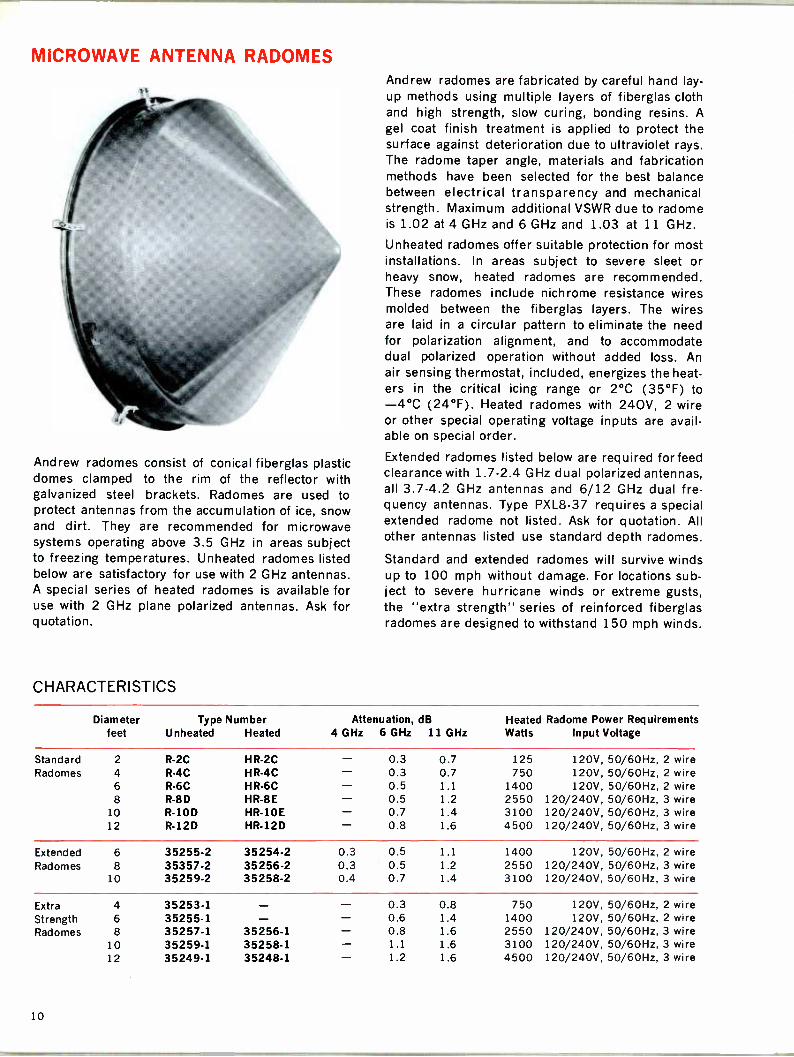
MICROWAVE ANTENNA RADOMES
Andrew radomes consist of conical fiberglas plastic domes clamped to the rim of the reflector with galvanized steel brackets. Radomes are used to protect antennas from the accumulation of ice, snow and dirt. They are recommended for microwave systems operating above 3.5 GHz in areas subject to freezing temperatures. Unheated radomes listed below are satisfactory for use with 2 GHz antennas. A special series of heated radomes is available for use with 2 GHz plane polarized antennas. Ask for q uotation.
CHARACTERISTICS
Andrew radomes are fabricated by careful hand lay- up methods using multiple layers of fiberglas cloth and high strength, slow curing, bonding resins. A
gel coat finish treatment is applied to protect the surface against deterioration due to ultraviolet rays. The radome taper angle, materials and fabrication methods have been selected for the best balance between electrical transparency and mechanical strength. Maximum additional VSWR due to radome is 1.02 at 4 GHz and 6 GHz and 1.03 at 11 GHz.
Unheated radomes offer suitable protection for most installations. In areas subject to severe sleet or heavy snow, heated radomes are recommended. These radomes include nichrome resistance wires molded between the fiberglas layers. The wires are laid in a circular pattern to eliminate the need for polarization alignment, and to accommodate dual polarized operation without added loss. An air sensing thermostat, included, energizes the heat- ers in the critical icing range or 2°C (35°F) to -4°C (24°F). Heated radomes with 240V, 2 wire or other special operating voltage inputs are avail- able on special order.
Extended radomes listed below are required for feed clearance with 1.7-2.4 GHz dual polarized antennas, all 3.7-4.2 GHz antennas and 6/12 GHz dual fre- quency antennas. Type PXL8-37 requires a special extended radome not listed. Ask for quotation. All other antennas listed use standard depth radomes.
Standard and extended radomes will survive winds up to 100 mph without damage. For locations sub- ject to severe hurricane winds or extreme gusts, the "extra strength" series of reinforced fiberglas radomes are designed to withstand 150 mph winds.
Diameter feet
Type Number Unheated Heated
Attenuation, dB 4 GHz 6 GHz 11 GHz
Heated Radome Power Requirements Watts Input Voltage
Standard 2 R -2C HR -2C - 0.3 0.7 125 120V, 50/60Hz, 2 wire Radomes 4 R -4C HR -4C - 0.3 0.7 750 120V, 50/60Hz, 2 wire
6 R -6C HR -6C - 0.5 1.1 1400 120V, 50/60Hz, 2 wire 8 R-8 D HR -8E - 0.5 1.2 2550 120/240V, 50/60Hz, 3 wire
10 R -10D HR -10E - 0.7 1.4 3100 120/240V, 50/60Hz, 3 wire 12 R -12D HR -12D - 0.8 1.6 4500 120/240V, 50/60Hz, 3 wire
Extended 6 35255-2 35254-2 0.3 0.5 1.1 1400 120V, 50/60Hz, 2 wire Radomes 8 35357-2 35256-2 0.3 0.5 1.2 2550 120/240V, 50/60Hz, 3 wire
10 35259-2 35258-2 0.4 0.7 1.4 3100 120/240V, 50/60Hz, 3 wire
Extra 4 35253.1 - - 0.3 0.8 750 120V, 50/60Hz, 2 wire Strength 6 35255-1 - - 0.6 1.4 1400 120V, 50/60Hz, 2 wire Radomes 8 35257-1 35256-1 - 0.8 1.6 2550 120/240V, 50/60Hz, 3 wire
10 35259-1 35258-1 - 1.1 1.6 3100 120/240V, 50/60Hz, 3 wire 12 35249-1 35248-1 - 1.2 1.6 4500 120/240V, 50/60Hz, 3 wire
10
.., a..._ .
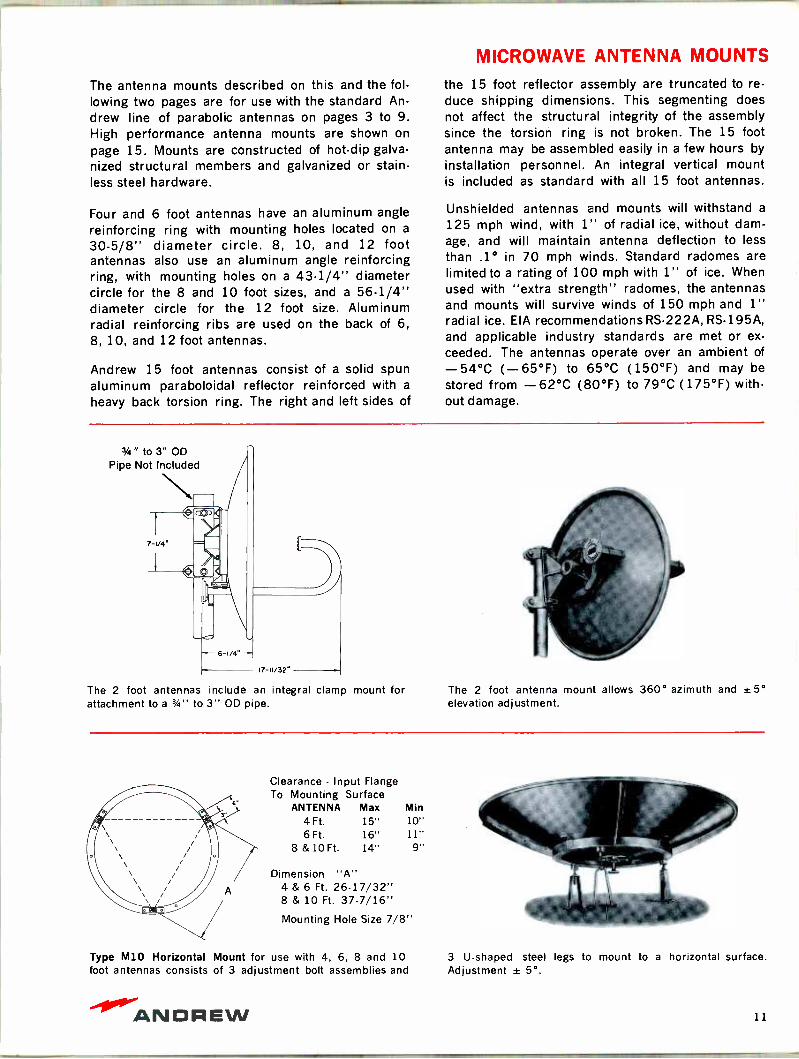
MICROWAVE ANTENNA MOUNTS
The antenna mounts described on this and the fol- lowing two pages are for use with the standard An-
drew line of parabolic antennas on pages 3 to 9. High performance antenna mounts are shown on
page 15. Mounts are constructed of hot -dip galva- nized structural members and galvanized or stain- less steel hardware.
Four and 6 foot antennas have an aluminum angle reinforcing ring with mounting holes located on a
30-5/8" diameter circle. 8, 10, and 12 foot antennas also use an aluminum angle reinforcing ring, with mounting holes on a 43-1/4" diameter circle for the 8 and 10 foot sizes, and a 56-1/4" diameter circle for the 12 foot size. Aluminum radial reinforcing ribs are used on the back of 6, 8, 10, and 12 foot antennas.
Andrew 15 foot antennas consist of a solid spun aluminum paraboloidal reflector reinforced with a
heavy back torsion ring. The right and left sides of
the 15 foot reflector assembly are truncated to re- duce shipping dimensions. This segmenting does not affect the structural integrity of the assembly since the torsion ring is not broken. The 15 foot antenna may be assembled easily in a few hours by installation personnel. An integral vertical mount is included as standard with all 15 foot antennas.
Unshielded antennas and mounts will withstand a
125 mph wind, with 1" of radial ice, without dam- age, and will maintain antenna deflection to less than .1° in 70 mph winds. Standard radomes are limited to a rating of 100 mph with 1" of ice. When used with "extra strength" radomes, the antennas and mounts will survive winds of 150 mph and 1" radial ice. EIA recommendations RS -222A, RS -195A, and applicable industry standards are met or ex-
ceeded. The antennas operate over an ambient of
-54°C (-65°F) to 65°C (150°F) and may be stored from -62°C (80°F) to 79°C (175°F) with- out damage.
3/4" to 3" OD Pipe Not Included
7-1/4"
The 2 foot antennas include an integral clamp mount for attachment to a 3/4" to 3" OD pipe.
The 2 foot antenna mount allows 360° azimuth and t5° elevation adjustment.
Clearance - Input Flange To Mounting Surface
ANTENNA Max Min 4 Ft. 15" 10" 6 Ft. 16" 11"
8 & 10 Ft. 14" 9,.
Dimension "A" 4 & 6 Ft. 26-17/32" 8 & 10 Ft. 37-7/16" Mounting Hole Size 7/8"
Type M10 Horizontal Mount for use with 4, 6, 8 and 10 foot antennas consists of 3 adjustment bolt assemblies and
3 U-shaped steel legs to mount to a horizontal surface. Adjustment ± 5°.
ANDREW 11

MICROWAVE ANTENNA MOUNTS
Type T4A Vertical Mount attaches 4 ft. and 6 ft. antennas to a 4-1/2" OD pipe. Elevation adjustment of ± 5° by threaded steel rod which also serves as a bottom suspension arm.
41/2" OD Pipe Not Included
/ A NOIE! U-16/IB
26/52 PUNA 1 rob YOURTUN
DIRECTLY TO FIAT SURFACE
22-1/52' FT ANTENNA 27.5/16 rt FT ANTENNA
p -6/Y -- nmA
Type T4B Vertical Mount, an offset T4A, includes a triang- ular structural frame with a 5 3/8" center offset, to allow clearance to radiator flanges. Includes a side strut with azi- muth adjustment of ±5° for alignment under windy conditions.
Type T10 Vertical Mount for use with 8 and 10 ft. antennas, mounts to 4-1/2" OD pipe. Includes one side arm strut with a ± 5° azimuth adjustment bolt assembly for use in
windy conditions. Mount is offset for convenient access to radiator.
Type T12C Vertical Mount for 12 ft. antennas is similar to Type T10. Mount is offset and includes one adjustable strut.
Type 38891 Side Strut is an optional fixed second strut to provide increased rigidity to Types T10 or T12C.
Vertical Tilt Mount,elevation adjustment- 5 to +50°degrees. Type 19474A for use with four and six foot reflectors. Type 31400 for use with eight and ten foot reflectors. Mount to 4-1/ 2" OD pipe.
41/2" OD Pipe Not Included
A Dimension
4 Ft Antenna Min (-5°) 7%" Max (+50°) 1317/
6 Ft Antenna Min (-5°) 8746" Max (+50°) 14'%"
8 and 10 Ft Min (-5°) 4" Antennas Max (+50°) 101/8"
B Dimension
20"
20"
33"
12
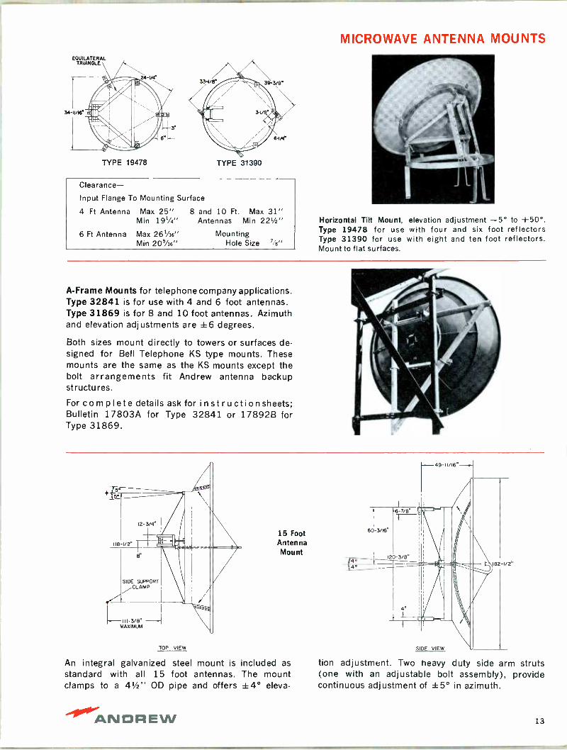
MICROWAVE ANTENNA MOUNTS EQUILATERAL
TRIANGLE
TYPE 19478 TYPE 31390
Clearance- Input Flange To Mounting Surface
4 Ft Antenna Max 25" 8 and 10 Ft. Max 31" Min 19'/4" Antennas Min 22'/2"
6 Ft Antenna Max 261/16" Mounting Min 205/16" Hole Size %"
Horizontal Tilt Mount, elevation adjustment -5° to +50°. Type 19478 for use with four and six foot reflectors Type 31390 for use with eight and ten foot reflectors. Mount to flat surfaces.
A -Frame Mounts for telephone company applications. Type 32841 is for use with 4 and 6 foot antennas. Type 31869 is for 8 and 10 foot antennas. Azimuth and elevation adjustments are ±6 degrees.
Both sizes mount directly to towers or surfaces de- signed for Bell Telephone KS type mounts. These mounts are the same as the KS mounts except the bolt arrangements fit Andrew antenna backup structures.
For complete details ask for instruction sheets; Bulletin 17803A for Type 32841 or 17892B for Type 31869.
+ 5'
12-3/4"
118-1/2"
SIDE SUPPORT /CLAMP
III -3/8" MAXIMUM
TOP VIEW
15 Foot Antenna Mount
An integral galvanized steel mount is included as standard with all 15 foot antennas. The mount clamps to a 41/2" OD pipe and offers ±4° eleva -
49 -11/16"
tion adjustment. Two heavy duty side arm struts (one with an adjustable bolt assembly), provide continuous adjustment of ±5° in azimuth.
ANDREW 13
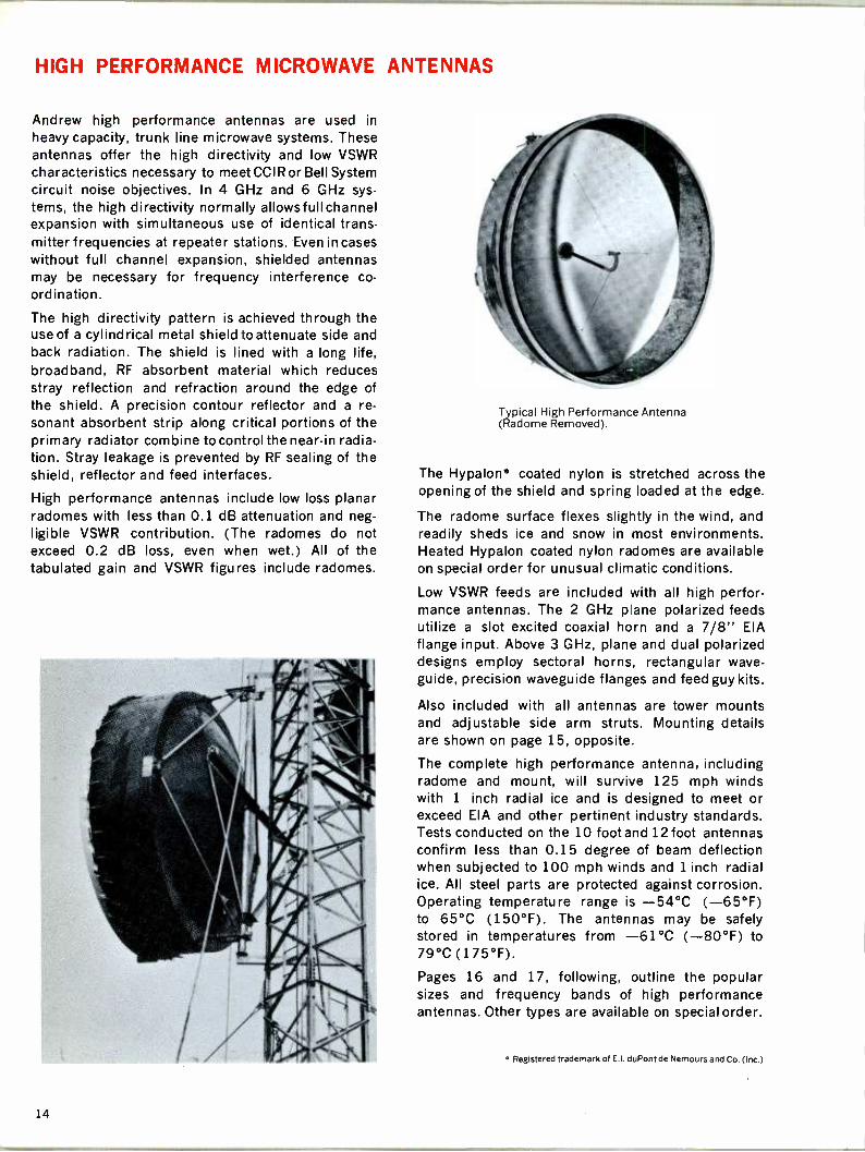
HIGH PERFORMANCE MICROWAVE ANTENNAS
Andrew high performance antennas are used in
heavy capacity, trunk line microwave systems. These antennas offer the high directivity and low VSWR characteristics necessary to meet CCIR or Bell System circuit noise objectives. In 4 GHz and 6 GHz sys- tems, the high directivity normally allowsfullchannel expansion with simultaneous use of identical trans- mitter frequencies at repeater stations. Even in cases without full channel expansion, shielded antennas may be necessary for frequency interference co-
ordination.
The high directivity pattern is achieved through the use of a cylindrical metal shield to attenuate side and back radiation. The shield is lined with a long life, broadband, RF absorbent material which reduces stray reflection and refraction around the edge of the shield. A precision contour reflector and a re- sonant absorbent strip along critical portions of the primary radiator combine to control the near -in radia- tion. Stray leakage is prevented by RF sealing of the shield, reflector and feed interfaces.
High performance antennas include low loss planar radomes with less than 0.1 dB attenuation and neg- ligible VSWR contribution. (The radomes do not exceed 0.2 dB loss, even when wet.) All of the tabulated gain and VSWR figures include radomes.
Typical High Performance Antenna (Radome Removed).
The Hypalon* coated nylon is stretched across the opening of the shield and spring loaded at the edge.
The radome surface flexes slightly in the wind, and readily sheds ice and snow in most environments. Heated Hypalon coated nylon radomes are available on special order for unusual climatic conditions.
Low VSWR feeds are included with all high perfor- mance antennas. The 2 GHz plane polarized feeds utilize a slot excited coaxial horn and a 7/8" EIA flange input. Above 3 GHz, plane and dual polarized designs employ sectoral horns, rectangular wave - guide, precision waveguide flanges and feed guy kits.
Also included with all antennas are tower mounts and adjustable side arm struts. Mounting details are shown on page 15, opposite.
The complete high performance antenna, including radome and mount, will survive 125 mph winds with 1 inch radial ice and is designed to meet or exceed EIA and other pertinent industry standards. Tests conducted on the 10 foot and 12foot antennas confirm less than 0.15 degree of beam deflection when subjected to 100 mph winds and 1 inch radial ice. All steel parts are protected against corrosion. Operating temperature range is -54°C (-65°F) to 65°C (150°F). The antennas may be safely stored in temperatures from -61°C (-80°F) to 79°C (175°F).
Pages 16 and 17, following, outline the popular sizes and frequency bands of high performance antennas. Other types are available on special order.
° Registered trademark of E.I. duPont de Nemours and Co. (Inc.)
14

LUZ
HIGH PERFORMANCE ANTENNA MOUNTING
High performance antennas include a torsion ring backup which serves as a structural element and as
an extended surface for mounting of the cylindrical metal shield.
OUTLINE DRAWING OF 8, 10 AND 12 FT SHIELDED ANTENNAS
The antennas include mounts which attach to a
41/2" OD pipe and permit ±5° elevation adjust- ment. Two adjustable side arm struts provide ±5° vernier azimuth adjustment.
SIDE SUPPORT CLAMP
F MAX.
TOP VIEW
Dimension, Inches A B C
7-3/4" I -I
3-1/4"
SIDE VIEW
C
D E
D
F
8 Ft Antenna 10 Ft Antenna 12 Ft Antenna
993/e 495/16 555/16 1021/8 96 90
1215/8 60% 58 1261/4 120 90 1465/8 72% 71 15015/16 145 90
Note: Dimension C is 5" larger than indicated when feed is WR229 rectangular waveguide.
OUTLINE DRAWING OF 15 FT SHIELDED ANTENNA
12-3/4"
118-1/2" {
8"
SIDE SUPPORT CLAMP
--I 113/8" MAXIMUM
TOP VIEW
60-3/16"
120-3/8"
SIDE VIEW
97-7/32"
188-1/8"
ANDREW 15

2 AND 4 GHz HIGH PERFORMANCE ANTENNAS
1.7-2.3 GHz Plane Polarized
Broadband coaxial horn radiator.
7/8" EIA 50 ohm input flange. Pressure tight to 5 psig.
7/8" and 1-5/8" HELIAX coaxial cable and fittings to feed these antennas are listed on pages 64-67.
Type EWP17 HELIAX elliptical waveguide to feed these antennas is listed on pages 22-29.
3.7-4.2 GHz Plane and Dual Polarized
WR229 Waveguide feeds.
CPR229G Input flanges.
Pressure tight to 5 psig.
Type EWP37 HELIAX elliptical waveguide to feed these antennas is listed on pages 22-29.
GUARANTEED ELECTRICAL CHARACTERISTICS 1.7-2.3 GHz
Frequency, GHz
and Type
Type
Number
Diameter
Feet
Gain, dBi
Bottom Mid Band Top
Front -to -Back
Ratio, dB
VSWR
Maximum
1.7 - 2.1 HP10-17 10 32.1 33.0 33.9 51 1.06
Plane HP12.17 12 33.6 34.5 35.4 55 1.06
Polarized KHP15-17 15 35.4 36.3 37.2 57 1.06
1.9 - 2.3 HP10-19 10 32.9 33.8 34.7 52 1.06
Plane HP12-19 12 34.5 35.4 36.3 56 1.06
Polarized KHP15-19 15 36.2 37.1 38:0 58 1.06
GUARANTEED ELECTRICAL CHARACTERISTICS 3.7-4.2 GHz
Frequency, GHz
and Type
Type
Number
Diameter
Feet Bottom
Gain, dBi
Mid Band Top
Front -to -Back
Ratio, dB
VSWR
Maximum
3.7 - 4.2 HP10-37 10 38.8 39.3 39.8 65 1.05
Plane
Polarized
HP12-37 12 40.3 40.8 41.3 65 1.05
3.7 - 4.2 HPX10-37 10 38.8 39.3 39.8 65 1.06
Dual
Polarized
HPX12-37 12 40.3 40.8 41.3 65 1.06
16

6, 7 AND 11 GHz HIGH PERFORMANCE ANTENNAS
5.925 - 6.425 GHz Plane and Dual Polarized
WR159 Waveguide feeds.
CPR159G Input flanges.
Type EWP56 HELIAX elliptical waveguide for use
with these antennas is described on pages 22-29.
7.125 -7.750 GHz Plane and Dual Polarized
WR112 Waveguide feeds.
CPR112G Input flanges.
Type EWP71 HELIAX elliptical waveguide for use
with these antennas is described on pages 22-29.
10.7 - 11.7 GHz Plane and Dual Polarized
WR90 Waveguide feeds.
CPR9OG Input flanges.
Type EWP107 HELIAX elliptical waveguide for use
with these antennas is described on pages 22-29.
All high performance antennas are supplied complete
with shielded reflector, low VSWR feed, feed guy kit
(except 2 GHz), planar radome , mount and side
struts. 15 foot antennas are shipped in a partially knockdown state, with the shield detached to reduce
shipping container size. Mounting details are shown
on page 15.
GUARANTEED ELECTRICAL CHARACTERISTICS 5.925 - 6.425 GHz
Frequency, GHz
and Type
Type
Number
Diameter
Feet
Gain, dBi
Bottom Mid Band Top
Front -to -Back
Ratio, dB
VSWR
Maximum
5.925-6.425 HPBA-59 8 40.7 41.1 41.5 65 1.04
Plane HP10A-59 10 42.6 43.0 43.4 70 1.04
Polarized HP12A-59 12 44.2 44.6 45.0 70 1.04
KHP15A-59 15 45.6 46.0 46.4 70 1.04
5.925-6.425 HPX8A-59 8 40.6 41.0 41.4 65 1.06
Dual HPX10A-59A 10 42.5 42.9 43.3 70 1.06
Polarized H PX 12A-59 12 44.1 44.5 44.9 70 1.06
H PX 15 A-59 15 45.5 45-9 46.3 70 1.06
GUARANTEED ELECTRICAL CHARACTERISTICS 7.125 - 7.750 GHz
Frequency, GHz
and Type
Type
Number
Diameter
Feet
Gain, dBi
Bottom Mid Band Top
Front -to -Back
Ratio, dB
VSWR
Maximum
7.125- 7.750 H P8-71 G 8 42.2 42.8 43.2 65 1.04
Plane HP10-71G 10 44.4 44.8 45.2 65 1.04
Polarized HP12-71G 12 46.0 46.4 46.8 65 1.04
7.125 - 7.750 HPX8-71G 8 42.1 42.7 43.1 65 1.06
Dual HPX10-71G 10 44.3 44.7 45.1 65 1.06
Polarized HPX12-71G 12 45.9 46.3 46.7 65 1.06
GUARANTEED ELECTRICAL CHARACTERISTICS 10.7 - 11.7 GHz
Frequency, GHz
and Type
Type
Number
Diameter
Feet
Gain, dBi
Bottom Mid Band Top
Front -to -Back
Ratio, dB
VSWR
Maximum
10.7 - 1 1.7 HP8-107 8 45.6 46.0 46.5 65 1.06
Plane
Polarized
HP10.107 10 47.3 47.7 48.1 65 1.06
10.7 - 1 1.7
Dual
HPX10.107A 10 47.1 47.5 47.9 65 1.10
Polarized
-40."ANDREW 17

MICROWAVE ANTENNA DATA
16 13 -
17 --
16
(/) 15- 0 Z 14
D O CL LL. Z 12
0 W II
cn 1-
Z Q 10
can 3 s pp á 6 o H Q
I I-6-á I- N U) 5
CC 4 2 I- 3
2
1
MAXIMUM THRUST VS. WIND VELOCITY I I I t I
60 70 80 90 100 110
WIND VELOCITY -MPH 120 130 140 150
ANTENNA THRUST
All Andrew antennas and mounts are designed to withstand at least 125 mph windloads with one inch of radial ice. The curves at left indicate the max- imum thrust in pounds on the supporting structure for the several sizes of standard and high perfor- mance antennas at winds of 60 to 150 mph (from worst direction).
The high performance antenna loads are with planar radome supplied with antenna. The standard antenna curves are without radomes. Antennas with radomes have one half the thrust shown.
For additional information on windloading charac- teristics or mechanical data, contact your Andrew sales engineer.
PARABOLIC ANTENNA BEAMWIDTH VS. GAIN
30
10
5.0
LO
.4
IO
BEAMWIDTH VS GAIN PARABOLIC ANTENNAS
15 20 25 30 35 40 45
ANTENNA GAIN, DBi 50 55
ANTENNA BEAM WIDTH
The curve at left shows the range of half power beamwidth angles as a function of antenna gain. The data are sufficient for most tower loading and twisting calculations.
If more precise information is needed regarding a
particular antenna, ask for the radiation pattern envelope (RPE) for that antenna. See page 3 for further description of RPE's available, and page 19 for typical pattern.
For any additional information on antenna patterns, gain, VSWR, guarantees, etc., contact your Andrew sales engineer.
VSWR CONVERSION CHART
VSWR Return Loss,dB
Reflection Coefficient,%
SWR dB VSWR
Return Reflection Loss,dB Coefficient,%
SWR dB VSWR
Return Loss,dB
Reflection SWR Coefficient,% dB
1.01 46.0 0.5 .086 1.08 28.3 3.8 .669 1.15 23.0 7.0 1.21 1.02 40.0 1.0 .172 1.09 27.4 4.3 .748 1.16 22.6 7.4 1.29 1.03 36.5 1.5 .256 1.10 26.4 4.8 .826 1.17 22.0 7.8 1.36 1.04 34.0 2.0 .304 1.11 25.5 5.2 .905 1.18 21.7 8.3 1.44 1.05 32.0 2.5 .424 1.12 24.9 5.7 .984 1.19 21.0 8.7 1.57 1.06 30.8 2.9 .506 1.13 24.0 6.0 1.06 1.20 20.8 9.1 1.58 1.07 29.4 3.4 .589 1.14 23.7 6.6 1.14 1.30 17.6 13.0 2.28
-
13-Z
7-
12 -- 15 FT.
11- -a
Z 10- w
-I- 8- Z - a
w 6- 12 FT.
-Z 7- - -CC O 6- 10 FT.
5-
4 - - 8 FT.
-2 3-
2 - 6 FT.
4 FT.
18

11w 1!
RADIATION PATTERN INFORMATION
Antenna gain was originally the all important micro- wave antenna electrical characteristic. However, in- creasing microwave usage has created a need for pattern detail of greater reliability for use in system design. EIA first recognized this need in the middle 1950's when the "keyhole" pattern was derived. Polar pattern plots were required of license appli- cants at that time. As spectrum congestion con- tinued, pattern information was published by sec- tors in tabular form. This, too, proved inadequate for difficult paths.
Andrew has developed the radiation pattern enve- lope (RPE) to fill the information gap between tab- ular gain, beamwidth and front -to -back ratio and
10
20
30
50
60
70
0
L- ---- -
detailed radiation patterns. Ease in reading is a
major advantage as is the reliability achieved through averaging.
The majority of system design needs will be met by
the use of gain and front -to -back ratio information and standard antennas. When these indicate an
interference problem, recourse is made to the RPE
for the standard antenna.
If this does not clear the problem, the next step is
to the detailed pattern, if the interference is small, or to the RPE of the corresponding shielded antenna if the interference is significant.
If interference is still indicated, one then proceeds in order to the detailed measured pattern of the
shielded antenna at the specific frequency, to a
larger antenna, or finally to a new site selection.
The example here shows the representative pattern enhancement that can be obtained through the use
of shielded antennas. The patterns shown are guar- anteed maximum parallel and cross polarized re-
sponse for ten foot antennas at 6 GHz.
Radiation pattern envelopes (both rectangular and
polar) are on file at the FCC, DOT, PMG's and OEM's. Additionally, they are available on request to users and planners. The patterns are available for all microwave antennas shown in this catalog.
5 10
,A.ore
60 90
AZIMUTH ± DEGREES FROM MAIN LOBE
STANDARD ANTENNA
`---- Mom - -- - - =M.
-,-+- -, - r-r----
SHIELDED ANTENNA:._
120 150 180
ANDREW 19
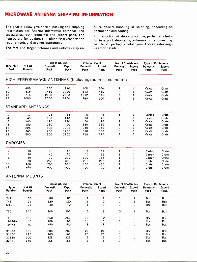
MICROWAVE ANTENNA SHIPPING INFORMATION
The charts below give normal packing and shipping information for Andrew microwave antennas and accessories, both domestic and export pack. The figures are for guidance in planning transportation requirements and are not guaranteed.
Ten foot and larger antennas and radomes may re-
quire special handling in shipping, depending on destination and routing.
For reduction of shipping volume, particularly help- ful in export shipments, antennas or radomes may be "bulk" packed. Contact your Andrew sales engi- neer for details.
Diameter Net Wt Feet Pounds
Gross Wt, Lbs Domestic Export
Pack Pack
Volume, Cu Ft
Domestic Export Pack Pack
No. of Containers Domestic Export
Pack Pack
Type of Containers Domestic Export
Pack Pack
HIGH PERFORMANCE ANTENNAS (Including radome and mount)
8 400 750 910 405 260 2 1 Crate Crate 10 515 1450 1800 643 416 2 1 Crate Crate 12 715 2100 2600 1212 675 2 1 Crate Crate 15 1000 2500 3200 860 900 2 1 Crate Crate
STANDARD ANTENNAS
2 17 25 65 5 6 1 1 Carton Crate 4 45 130 140 20 23 2 1 Crate Crate 6 100 180 280 50 70 2 1 Crate Crate 8 150 380 400 150 150 2 1 Crate Crate
10 225 800 1000 340 340 2 1 Crate Crate 12 365 1200 1700 550 550 2 1 Crate Crate 15 500 1600 2200 710 710 2 1 Crate Crate
RADOMES
2 10 15 45 9 12 1 1 Carton Crate 4 20 40 120 40 52 1 1 Carton Crate 6 30 70 200 100 135 1 1 Carton Crate 8 70 230 300 230 230 1 1 Crate Crate
10 100 700 800 450 450 1 1 Crate Crate 12 140 900 1000 700 700 1 1 Crate Crate
ANTENNA MOUNTS
Gross Wt, Lbs Volume, Cu Ft No. of Containers Type of Containers Type Net Wt Domestic Export Domestic Export Domestic Export Domestic Export
Number Pounds Pack Pack Pack Pack Pack Pack Pack Pack
T4A 68 80 80 1 2 1 1 Box Box T4B 91 120 120 1 2 1 1 Box Box M10 21 40 40 1 1 1 1 Box Box
T10 140 200 200 6 8 3 1 Box Box
T12 163 250 250 10 12 1 1 Box Box 19474A 80 100 100 10 10 1 1 Box Box 19478 87 150 150 18 18 1 1 Box Box
31390 160 200 200 20 20 1 1 Box Box 31400 190 165 165 25 25 1 1 Box Box 31869 300 325 325 5 5 1 1 Box Box 32841 150 165 165 3 3 1 1 Box Box
20
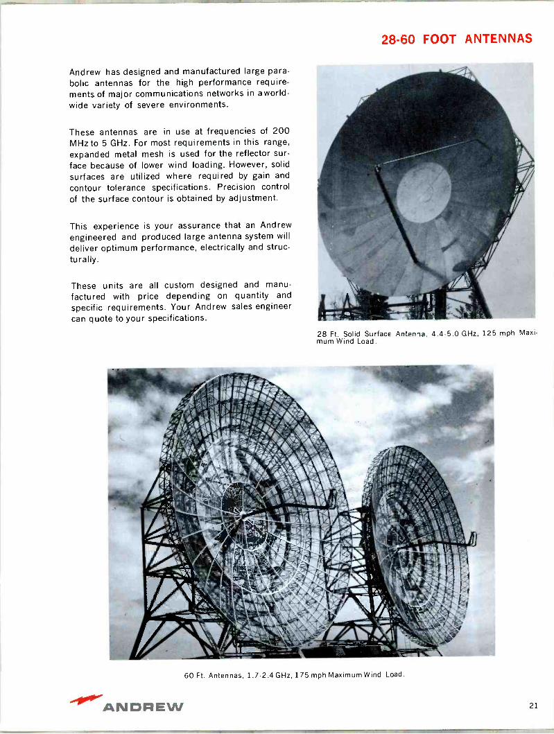
28-60 FOOT ANTENNAS
Andrew has designed and manufactured large para-
bolic antennas for the high performance require- ments of major communications networks in a world- wide variety of severe environments.
These antennas are in use at frequencies of 200 MHz to 5 GHz. For most requirements in this range,
expanded metal mesh is used for the reflector sur-
face because of lower wind loading. However, solid
surfaces are utilized where required by gain and
contour tolerance specifications. Precision control of the surface contour is obtained by adjustment.
This experience is your assurance that an Andrew engineered and produced large antenna system will deliver optimum performance, electrically and struc- turally.
These units are all custom designed and manu-
factured with price depending on quantity and
specific requirements. Your Andrew sales engineer can quote to your specifications.
28 Ft. Solid Surface Antenna, 4.4-5.0 GHz, 125 mph Maxi- mum Wind Load.
60 Ft. Antennas, 1.7-2.4 GHz, 175 mph Maximum Wind Load.
-40°'ANDF;EW 21
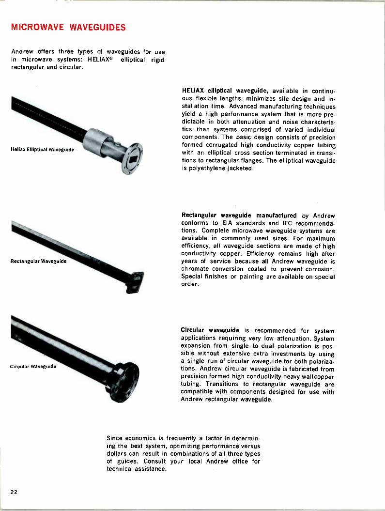
MICROWAVE WAVEGUIDES
Andrew offers three types of waveguides for use in microwave systems: HELIAX® elliptical, rigid rectangular and circular.
Heliax Elliptical Waveguide
Rectangular Waveguide
Circular Waveguide
HELIAX elliptical waveguide, available in continu- ous flexible lengths, minimizes site design and in- stallation time. Advanced manufacturing techniques yield a high performance system that is more pre- dictable in both attenuation and noise characteris- tics than systems comprised of varied individual components. The basic design consists of precision
.09)- formed corrugated high conductivity copper tubing ' with an elliptical cross section terminated in transi- tions to rectangular flanges. The elliptical waveguide is polyethylene jacketed.
Rectangular waveguide manufactured by Andrew conforms to EIA standards and IEC recommenda- tions. Complete microwave waveguide systems are available in commonly used sizes. For maximum efficiency, all waveguide sections are made of high conductivity copper. Efficiency remains high after years of service because all Andrew waveguide is chromate conversion coated to prevent corrosion. Special finishes or painting are available on special order.
Circular waveguide is recommended for system applications requiring very low attenuation. System expansion from single to dual polarization is pos- sible without extensive extra investments by using a single run of circular waveguide for both polariza- tions. Andrew circular waveguide is fabricated from precision formed high conductivity heavy wall copper tubing. Transitions to rectangular waveguide are compatible with components designed for use with Andrew rectangular waveguide.
Since economics is frequently a factor in determin- ing the best system, optimizing performance versus dollars can result in combinations of all three types of guides. Consult your local Andrew office for technical assistance.
22
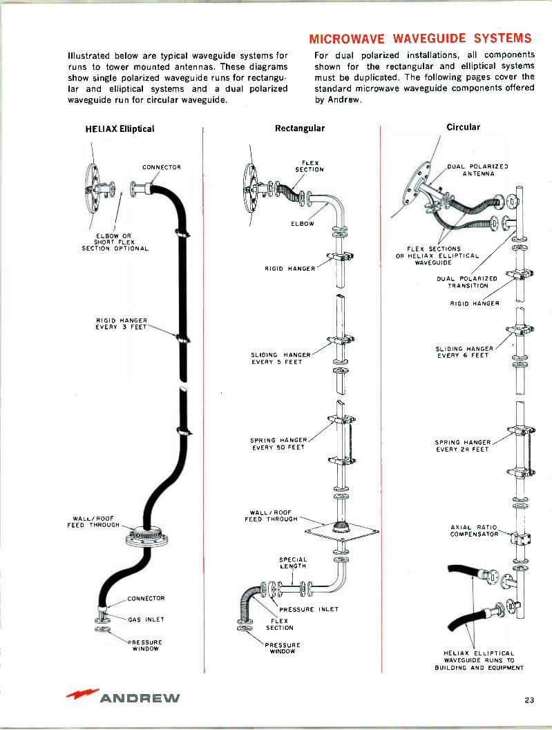
Illustrated below are typical waveguide systems for runs to tower mounted antennas. These diagrams show single polarized waveguide runs for rectangu- lar and elliptical systems and a dual polarized waveguide run for circular waveguide.
HELIAX Elliptical
CONNECTOR
ELBOW OR SHORT FLEX
SECTION OPTIONAL
RIGID HANGER EVERY 3 FEET
WALL/ ROOF FEED THROUGH
CONNECTOR
GAS INLET
PRESSURE WINDOW
MICROWAVE WAVEGUIDE SYSTEMS For dual polarized installations, all components shown for the rectangular and elliptical systems must be duplicated. The following pages cover the standard microwave waveguide components offered by Andrew.
Rectangular
FLE X
SECTION
RIGID HANGER
SLIDING HANGER EVERY 5 FEET
SPRING HANGER EVERY 50 FEET
WALL/ROOF FEED THROUGH
SPECIAL LENGTH
PRESSURE
FLEX SECTION
PRESSURE WINDOW
INLET
Circular
DUAL POLARIZED ANTENNA
Gj%ii/ü,ÏIIIW\\"
FLEX SECTIONS OR HELIAX ELLIPTICAL
WAVEGUIDE
DUAL POLARIZED TRANSITION
RIGID HANGER
SLIDING HANGER EVERY 6 FEET
SPRING HANGER EVERY 24 FEET
AXIAL RATIO COMPENSATOR
HELIAX ELLIPTICAL WAVEGUIDE RUNS TO
BUILDING AND EQUIPMENT
"4.811. -ANDREW 23
MICROWAVE WAVEGUIDE ATTENUATION
7.0
6.0
5.0
4.0
3.0
2.0
1.5
1.0
0.9
0.8
0.7
0.6
0.5
0.4
0.3
0.25
EW20
EW17
\
\
'...
EW37
,.,_;. ..
..T
EW44 \ \ \\
EW56 EW 59
\ \ --WR137
WR112
\
\ .
\, WR159
\ WR187s,
WR229
--. WR284
WR340
-wRá3Q ry
'-Y
a...}..;..
1
-WC150
_... .....1..
15 2 3 4 5 6 7 8 9 10 15 20
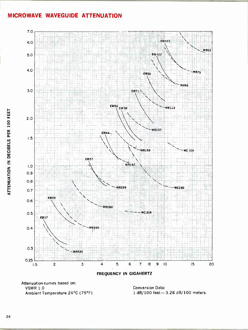
Attenuation curves based on: VSWR 1.0 Ambient Temperature 24°C (75°F)
FREQUENCY IN GIGAHERTZ
Conversion Data: 1 dB/100 feet -3.28 dB/100 meters
24

HELIAX ® ELLIPTICAL WAVEGUIDE Low Attenuation Low VSWR Continuous Flexible Lengths Reduces Station Layout Time Reduces Installation Time Lower Cost with Better System Performance
HELIAX elliptical waveguide* is available for the commonly used bands between 1.7 and 13.2 GHz. Designs for other frequency ranges are under de-
velopment. Elliptical waveguide connectors are avail-
able to mate with U.S. Military, U.S. EIA, and inter- national IEC type flanges.
ATTENUATION The attenuation of an elliptical waveguide assembly is generally lower than that of the equivalent rec-
tangular copper waveguide. The attenuation charac- teristics of Andrew HELIAX elliptical waveguide are shown on the opposite page along with values for rigid rectangular and circular waveguides.
VSWR
Elliptical waveguide provides a complete feeder run with known VSWR characteristics. On the other hand, the VSWR of rigid waveguide installations depends upon the combination of components with different VSWR specifications ranging from 1.01 to 1.05 each.
HELIAX elliptical waveguide assemblies consist of
flexible corrugated copper tubes of elliptical cross section with waveguide transitions to conventional rectangular flanges at each end. The elliptical cross section propagates the eTE11 dominant mode similar to the TE,,, dominant mode in rectangular wave - guide. The continous construction eliminates the multiple joints of miscellaneous bends, flex sections,
CHARACTERISTICS
and rigid sections inherent in a rectangular wave -
guide installation. The waveguide includes a rugged
black polyethylene jacket which provides protection in handling and installation.
Two versions of elliptical waveguide are offered by
Andrew. Standard elliptical waveguide is recom-
mended for short and medium haul radio relay
systems. Premium type elliptical waveguide assem-
blies with tuned connectors are recommended for long haul, high capacity radio systems. The standard and premium elliptical waveguides differ only in
attainable assembly VSWR.
All assemblies are VSWR sweep tested and shipped pressurized.
Frequency Band, GHz
Type Number Standard Premium
Dimensions Over Jacket, inches
Minimum Bending Radii, inches
E Plane H Plane Weight
Pounds per Foot
1.7-2.4 EW17 EWP17 5.675 x 3.050 28 81 2.73
1.9-2.7 EW20 5.020 x 2.831 26 71 2.02
3.3-4.3 EW37 EWP37 2.896 x 1.855 17 41 1.01
4.2-5.1 EW44 EWP44 2.312 x 1.590 15 32 0.74
4.9-6.425 EW56 EWP56 1.964 x 1.270 12 27 0.62 5.3-7.125 EW59 EWP59 1.857 x 1.196 11 26 0.53
6.5-8.5 EW71 EWP71 1.550 x 1.022 9 22 0.43
7.7-10.0 EW85 1.324 x 0.903 8 19 0.36
8.9-11.7 EW107 EWP107 1.163 x 0.796 7 16 0.32 10.0-13.2 EW122 EWP122 1.070 x 0.718 6 15 0.29
Licensed for use or resale under United States Patent No. 3,200,356 and certain patents of the U.S.A., Canada and other countries. LIMITED LICENSE under pertinent patents of most countries In Europe and Asia to Importations by a purchaser as part of a complete microwave system. Further Information on Inquiry. HELIAX' Is the registered trademark under which elliptical waveguides are sold by Andrew Corporation.
ANDREW 25
HELIAX ®ELLIPTICAL WAVEGUIDE
ELLIPTICAL WAVEGUIDE ASSEMBLIES
HELIAX elliptical waveguide assemblies are available as either standard guide with untuned connectors or premium guide with tuned connectors. Connect- ors are factory attached at no extra charge.
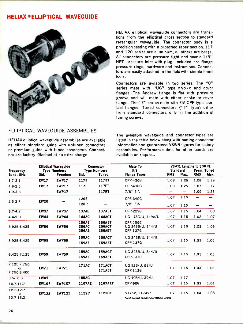
HELIAX elliptical waveguide connectors are transi- tions from the elliptical cross section to standard rectangular waveguide. The connector body is a
precision casting with a broached taper section. 117 and 120 series are aluminum, all others are brass. All connectors are pressure tight and have a 1/8" NPT pressure inlet with plug. Included are flange pressure rings, hardware and instructions. Connec- tors are easily attached in the field with simple hand tools.
Connectors are avilable in two series. The "C" series mate with "UG" type choke and cover flanges. The Andrew flange is flat with pressure groove and will mate with either choke or cover flange. The "E" series mate with EIA CPR type con- tact flanges. Tuned connectors ("T" type) differ from standard connectors only in the addition of tuning screws.
The available waveguide and connector types are listed in the table below along with mating connector information and guaranteed VSWR figures for factory assemblies. Performance data for other bands are available on request.
Frequency Band, GHz
Elliptical Waveguide Type Numbers
Std. Premium
Connector Type Numbers
Std. Tuned
Mate To U.S.
Flange Types
VSWR, Lengths to 300 Ft. Standard Prem. Tuned
RMS Max. RMS Max.
1.7-2.1 EW17 EWP17 117E 117ET CPR -430G 1.09 1.25 1.08 1.19
1.9-2.3 EW17 EWP17 117E 117ET CPR -430G 1.09 1.25 1.07 1.17
1.9-2.3 - EWP17 117RT 7/8" EIA 1.09 1.23
120E CPR -340G 1.07 1.15 2.5-2.7 EW20
120R 7/8" EIA 1.07 1.15
3.7-4.2 EW37 EWP37 137AE 137AET CPR -229G 1.07 1.15 1.04 1.08
4.4-5.0 EW44 EWP44 144AC 144ACT UG-148C/U, 149A/U 1.07 1.15 1.03 1.07
156AE 156AET CPR -159G 5.925-6.425 EW56 EWP56 256AC 256ACT UG-343B/U, 344/U 1.07 1.15 1.03 1.06
256AE 256AET CPR -137G
159AC 159ACT UG-343B/U, 344/U 5.925-6.425 EW59 EWP59
159AE 159AET CPR -137G 1.07 1.15 1.03 1.06
159AC 159ACT UG-343B/U, 344/U 6.425-7.125 EW59 EWP59 1.07 1.15 1.03 1.05
159AE 159AET CPR -137G
7.125-7.750 171AC 171ACT UG-52B/U, 51/U or
7.7 50-8.400 EW71 EWP71
171AET CPR -112G 1.07 1.15 1.03 1.06
8.5-10.0 EW85 185AC UG-40B/U, 39/U 1.07 1.17 - - 10.7.11.7 EW107 EWP107 1107AE 1107AET CPR -90G 1.07 1.15 1.03 1.06
12.2-12.7 or EW122 EWP122 1122C 1122CT 51752, 51745* 1.07 1.15 1.04 1.08
12.7-13.2 Andrew part numbers for WR75 Flanges
26

HELIAX ®ELLIPTICAL WAVEGUIDE
SHIPPING INFORMATION
The table below shows the maximum lengths of elliptical waveguide (either standard or premium- with or without connectors) shipped in wood crates or on disposable wooden reels. The four foot reel has a tare weight, with lagging, of 94 pounds. The
six foot reel tare weight is 315 pounds with lagging.
Longer lengths than shown are shipped on return- able deposit type reels. For further information ask your Andrew sales engineer.
SHIPPING INFORMATION
Type Number
Weight, Lbs. Per Foot
Maximum Length, Feet
Wood Crates Size
Inches Tare Weight
Pounds
Disposable Wooden Reels Capacity, Feet
48" Dia. x 24"W 72" Dia. x 31"W
EW17 2.73 75 86x86x20 210 EW20 2.02 75 86x86x20 210
EW37 1.01 100 72x72x24 125 101-425
EW44 0.74 135 57x57x16 110 135-450
EW56 0.62 145 57x57x16 90 146-550
EW59 0.53 150 57x57x16 90 151-600
EW71 0.43 175 48x48x15 75 176-450 451.800 EW85 0.36 200 46x46x16 70 201-550 551-1000
EW107 0.32 200 46x46x15 68 201-550 551-1200 EW122 0.29 200 46x46x14 66 201-600 601-1200
WAVEGUIDE AND FLANGE NOMENCLATURE
The table below lists the popular U.S. waveguide and flange standard types and the IEC equivalents. Andrew elliptical waveguide connectors will mate to the appropriate IEC flanges listed. Andrew standard connectors do not, however, include the alignment
pins or holes or alignment bolts used in some IEC
designs. In addition there are some differences in gasket style and depth. Special designs are available on special order.
WAVEGUIDE AND FLANGE NOMENCLATURE
Frequency Band, GHz
Waveguide Types EIA MIL IEC
U.S. Military Flanges
Choke Cover Choke
IEC Flanges
Cover Cover/ Gasket
Contact Flanges
EIA IEC
1.7-2.6 WR430 RG104/U R22 - - CPR430G PDR22 2.2-3.3 WR340 RG112/U R26 CPR340G PDR26
2.6-3.95 WR284 RG48/U R32 UG54B/U UG53/U CAR32 UAR32 PAR32 CPR284G PDR32
3.3-4.9 WR229 - R40 CPR229G PDR40
3.95-5.85 WR187 RG49/U R48 UG148C/U UG149A/U CAR48 UAR48 PAR48 CPR187G PDR48 4.9-7.05 WR159 - R58 - CAR58 UAR58 PAR58 CPR159G PDR58
5.85-8.2 WR137 RG50/U R70 UG343B/U UG344/U CAR70 UAR70 PAR70 CPR137G PDR70 7.05-10.0 WR112 RG51/U R84 UG52B/U UG51/U CBR84 UBR84 PBR84 CPR112G PDR84
8.2-12.4 WR90 RG52/U R100 UG40B/U UG39/U CBR100 UBR100 PBR100 CPR9OG PDR100 10.0-15.0 WR75 - R120 51752* 51745*
12.4-18.0 WR62 RG91/U R140 UG541/U UG419/U
°Andrew part numbers for WR75 Flanges
ANDREW 27

HELIAX® ELLIPTICAL WAVEGUIDE ACCESSORIES
I Splice Fitting for use with either standard or premi- um elliptical waveguide.
Hoisting Grip use at 200 ft. intervals to raise guide on tower.
Bending Tool Kit for ellipti- cal waveguide installation. One each E and H plane form included.
Wall/Roof Feed Through Molded rubber "boot" type.
Grounding Kit is typically used near tower base and ends of run.
Waveguide Hanger Kit includes 10 stainless steel hangers. Use one hanger every 3 feet.
Round Member Adaptor Kit includes 10 stainless clamps to mount hangers to round support mem- bers. Two kits are required for use with each EW17
or EW20 hanger kit. Member Type Diameter No. 1" - 2" 31670-1 2" - 3" 31670-2 3" - 4" 31670-3 4" - 5" 31670-4 5" - 6" 31670-5
Angle Adaptor Kit in- cludes 10 clamps to mount waveguide hang- ers to angle members .
Type 31768-1
Ceiling Bracket to mount waveguide hangers to ceil-
ing or wall Type 31771-1
Portable Reels
Capacity 100 feet of Types EW56, 59 or 71, 200 feet of Types EW107 or 122. Diameter 44", width 24", weight 24 pounds.
Type 34397-1
Capacity 200 feet of Types EW56, 59 or 71, 400 feet of Types EW107 or 122. Diameter 54" width 24", weight 32 pounds.
Type 34397-3
supports either reel above, roller type, Reel Stand fastens to side of reel for storage . . Type 34405-1
INSTALLATION ACCESSORIES
Waveguide Splice Hoisting Bending Type Fitting Grip Tool Kit
EW17 117Z 34759 33586-4 EW20 120Z 34759 33586-4 EW37 137AZ 31535 33586-3 EW44 144AZ 24312A 33586-3 EW56 156AZ 24312A 33586-2 EW59 159AZ 29961 33586-2 EW71 171AZ 19256B 33586-1 EW85 185AZ 29958 33586-1 EW107 1107AZ 29958 33586-1 EW122 1122AZ 29958 33586-1
Feed Grounding Waveguide Through Kit Hanger Kit
35849-10 30417-3 31766-9 35849-9 30417-5 31766-10 35849-8 33212 31766-4 35849-7 24811-2 31766-2 35849-6 24811-2 31766-7 35849-5 24811-2 31766-1 35849-4 33211 31766-3 35849-3 24810-2 31766-5 35849-2 24810-2 31766-6 35849-1 24810-2 31766-8
28
HELIAX ® ELLIPTICAL WAVEGUIDE INSTALLATION
The availability of HELIAX elliptical waveguide in long lengths and the guide flexibility normally allow a "one piece" installation with connectors only at equipment and antenna terminations. Installation instructions are included with each shipment for information.
All HELIAX elliptical waveguide con- nectors can be attached in the field with ordinary hand tools. Complete instruc- tions are included with each connector.
PREPARATION
The transmitting equipment and an- tenna should be installed prior to the waveguide. Inspect the guide for pos-
sible shipping damage and pressure loss. Bulk waveguide and assemblies are pressure tested at 10 psig prior to shipping and are shipped pressurized.
Factory attached connectors are shipped with blank cover plates attached to re-
tain pressure during shipment. Do not remove blank covers until connection to equipment as they afford protection to the connector face and prevent entry of foreign matter.
When unfitted guide is used, attach the connector to the antenna end before hoisting. Pressure test the assembly prior to hoisting.
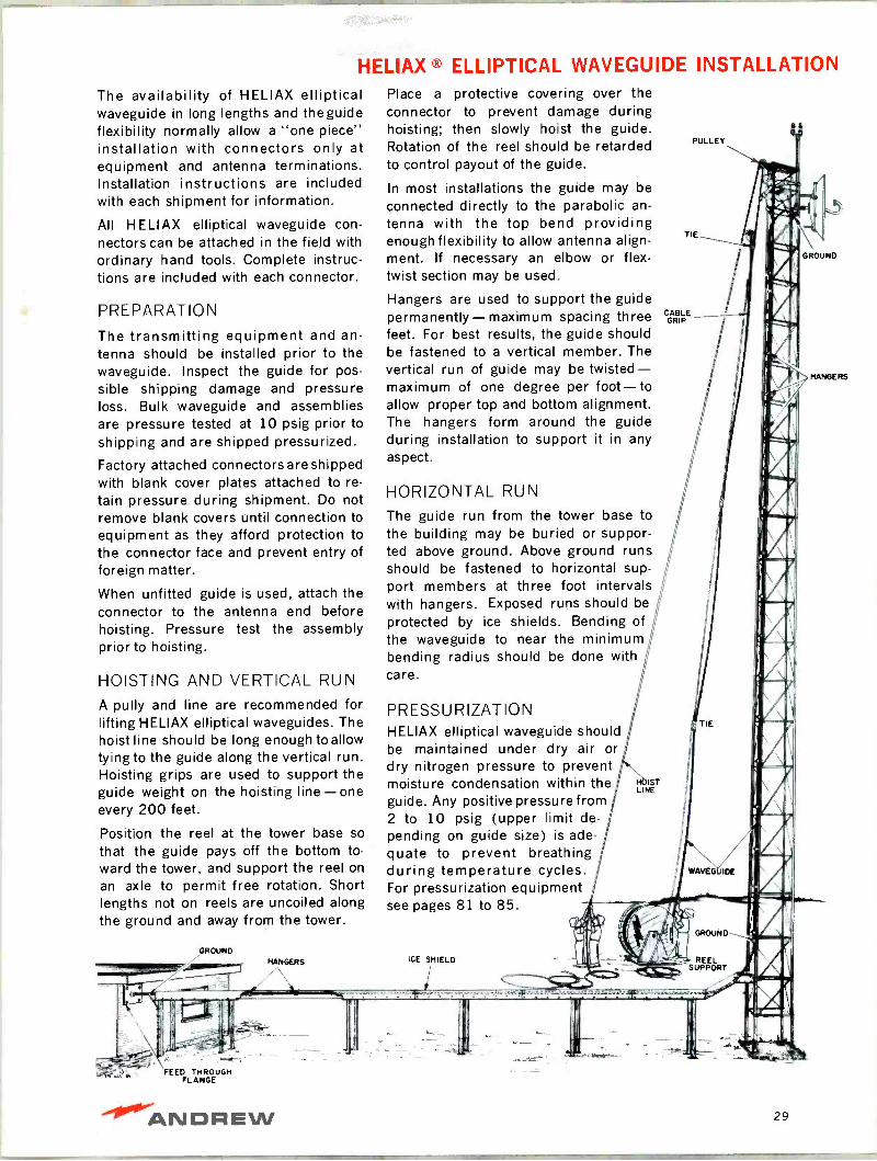
HOISTING AND VERTICAL RUN
A pully and line are recommended for lifting HELIAX elliptical waveguides. The hoist line should be long enough toallow tying to the guide along the vertical run. Hoisting grips are used to support the guide weight on the hoisting line-one every 200 feet.
Position the reel at the tower base so
that the guide pays off the bottom to- ward the tower, and support the reel on
an axle to permit free rotation. Short lengths not on reels are uncoiled along the ground and away from the tower.
GROUND
FEED THROUGH FLANGE
Place a protective covering over the connector to prevent damage during hoisting; then slowly hoist the guide. Rotation of the reel should be retarded to control payout of the guide.
In most installations the guide may be connected directly to the parabolic an-
tenna with the top bend providing enough flexibility to allow antenna align- ment. If necessary an elbow or flex - twist section may be used.
Hangers are used to support the guide permanently- maximum spacing three feet. For best results, the guide should be fastened to a vertical member. The vertical run of guide may be twisted- maximum of one degree per foot-to allow proper top and bottom alignment. The hangers form around the guide during installation to support it in any aspect.
HORIZONTAL RUN
The guide run from the tower base to the building may be buried or suppor- ted above ground. Above ground runs should be fastened to horizontal sup- port members at three foot intervals with hangers. Exposed runs should be
protected by ice shields. Bending of the waveguide to near the minimum bending radius should be done with care.
PRESSURIZATION HELIAX elliptical waveguide should be maintained under dry air or dry nitrogen pressure to prevent moisture condensation within the guide. Any positive pressure from 2 to 10 psig (upper limit de- pending on guide size) is ade- quate to prevent breathing during temperature cycles. For pressurization equipment see pages 81 to 85.
ICE SHIELD
ANDREW 29
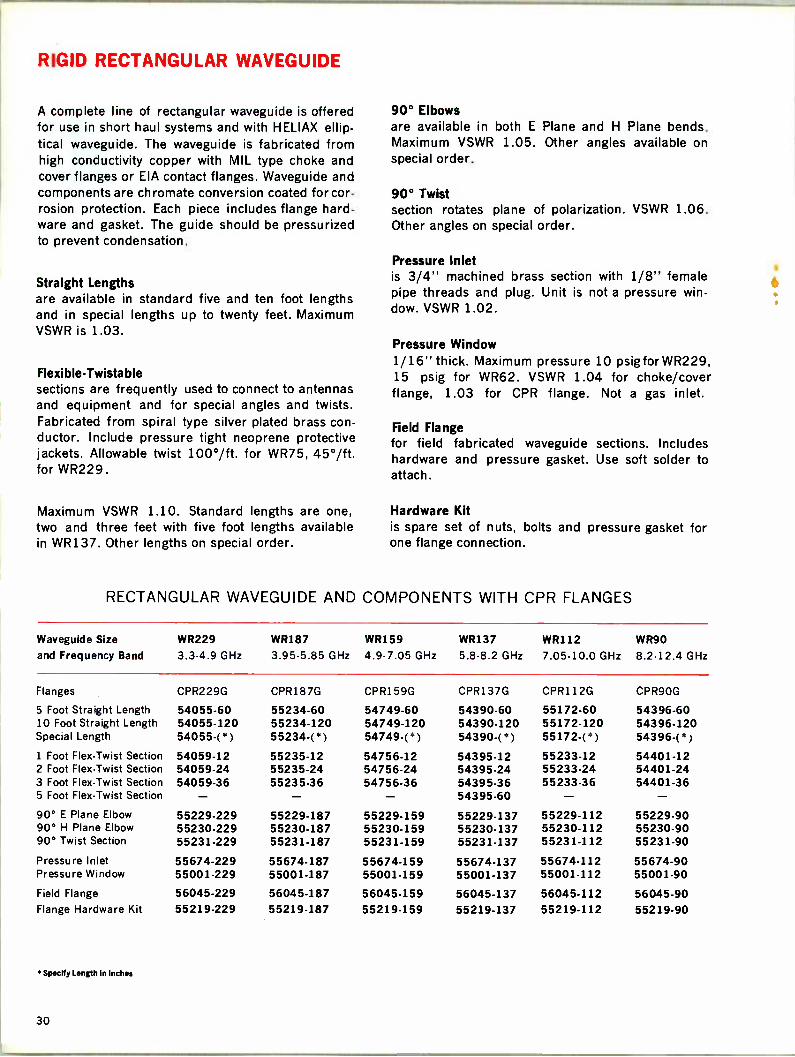
RIGID RECTANGULAR WAVEGUIDE
A complete line of rectangular waveguide is offered for use in short haul systems and with HELIAX ellip- tical waveguide. The waveguide is fabricated from high conductivity copper with MIL type choke and cover flanges or EIA contact flanges. Waveguide and components are chromate conversion coated for cor- rosion protection. Each piece includes flange hard- ware and gasket. The guide should be pressurized to prevent condensation.
Straight Lengths are available in standard five and ten foot lengths and in special lengths up to twenty feet. Maximum VSWR is 1.03.
Flexible-Twista ble sections are frequently used to connect to antennas and equipment and for special angles and twists. Fabricated from spiral type silver plated brass con- ductor. Include pressure tight neoprene protective jackets. Allowable twist 100°/ft. for WR75, 45°/ft. for WR229.
Maximum VSWR 1.10. Standard lengths are one, two and three feet with five foot lengths available in WR137. Other lengths on special order.
90° Elbows are available in both E Plane and H Plane bends. Maximum VSWR 1.05. Other angles available on special order.
90° Twist section rotates plane of polarization VSWR 1.06. Other angles on special order.
Pressure Inlet is 3/4" machined brass section with 1/8" female pipe threads and plug. Unit is not a pressure win- dow. VSWR 1.02.
Pressure Window 1/16" thick. Maximum pressure 10 psigfor WR229, 15 psig for WR62. VSWR 1.04 for choke/cover flange, 1.03 for CPR flange. Not a gas inlet.
Field Flange for field fabricated waveguide sections. Includes hardware and pressure gasket. Use soft solder to attach.
Hardware Kit is spare set of nuts, bolts and pressure gasket for one flange connection.
RECTANGULAR WAVEGUIDE AND COMPONENTS WITH CPR FLANGES
Waveguide Size
and Frequency Band
WR229
3.3-4.9 GHz
WR187
3.95-5.85 GHz
WR159
4.9-7.05 GHz
WR137
5.8-8.2 GHz
WR112
7.05-10.0 GHz
WR90
8.2-12.4 GHz
Flanges CPR229G CPR187G CPR159G CPR137G CPR112G CPR9OG
5 Foot Straight Length 54055-60 55234-60 54749-60 54390.60 55172-60 54396-60 10 Foot Straight Length 54055-120 55234.120 54749-120 54390-120 55172.120 54396-120 Special Length 54055-(*) 55234-('") 54749-(' ) 54390-(") 55172-('` ) 54396-(') 1 Foot Flex -Twist Section 54059-12 55235-12 54756-12 54395-12 55233-12 54401-12 2 Foot Flex -Twist Section 54059-24 55235-24 54756-24 54395-24 55233-24 54401-24 3 Foot Flex -Twist Section 54059-36 55235-36 54756-36 54395-36 55233-36 54401-36 5 Foot Flex -Twist Section 54395-60 - - 90° E Plane Elbow 55229-229 55229-187 55229-159 55229-137 55229-112 55229-90 90° H Plane Elbow 55230-229 55230-187 55230-159 55230-137 55230-112 55230-90 90° Twist Section 55231-229 55231-187 55231-159 55231-137 55231-112 55231-90
Pressure Inlet 55674-229 55674-187 55674-159 55674-137 55674-112 55674-90 Pressure Window 55001-229 55001-187 55001-159 55001-137 55001-112 55001-90
Field Flange 56045-229 56045-187 56045-159 56045-137 56045-112 56045-90 Flange Hardware Kit 55219-229 55219-187 55219-159 55219-137 55219-112 55219-90
° Specify Length in Inches
30

RIGID RECTANGULAR WAVEGUIDE
E Plane Elbow
Twist
Pressure Inlet
H Plane Elbow
Field Flange
Pressure Window
Straight Section
Flex -Twist Section
RECTANGULAR WAVEGUIDE AND COMPONENTS WITH CHOKE/COVER FLANGES
Waveguide Size WR187 WR137 WR112 WR90 WR75 WR62 and Frequency Band 3.95-5.85 GHz 5.8-8.2 GHz 7.05-10.0 GHz 8.2-12.4 GHz 10.0-15.0 GHz 12.4-18.0 GHz
Flanges, Choke UG-148C/U UG-343B/U UG-52B/U UG-40B/U 517521* UG-541/U Cover UG-149A/U UG-344/U UG-51/U UG-39/U 51745t UG-419/U
5 Foot Straight Length 52080-60 19065-60 19045-60 19051-60 51741-60 53210-60 10 Foot Straight Length 52080-120 19065-120 19045-120 19051-120 51741-120 53210-120 Special Length 52080-(*) 19065-0) 19045-(*) 19051-(*) 51741-(*) 53210-(*) 1 Foot Flex -Twist Section 52095-12 19075-12 51727-12 51737-12 51747-12 53215-12 2 Foot Flex -Twist Section 52095-24 19075-24 51727-24 51737-24 51747-24 53215-24 3 Foot Flex -Twist Section 52095-36 19075-36 51727-36 51737-36 51747-36 53215-36 5 Foot Flex -Twist Section - 19075-60
90°E Plane Elbow 55220-187 55220-137 55220-112 55220-90 55220-75 55220-62 90°H Plane Elbow 55221-187 55221-137 55221-112 55221-90 55221-75 55221-62 90° Twist Section 55222-187 55222-137 55222-112 55222-90 55222-75 55222-62
Pressure Inlet 55675-187 55675-137 55675-112 55675-90 55675-75 55675-62 Pressure Window 55000-187 55000-137 55000-112 55000-90 55000-75 55000-62 Field Choke Flange 53015-187 53015-137 53015-112 53015-90 53015-75 53015-62 Field Cover Flange 53025-187 53025-137 53025-112 53025-90 53025-75 53025-62 Flange Hardware Kit 55224-187 55224-137 55224-112 55224-90 55224-75 55224-62
°Specify Length in Inches tAndrew Part Number For WR75 Flanges.
ANDREW 31

RECTANGULAR WAVEGUIDE ACCESSORIES
Tapered Waveguide Transition
Rigid or Sliding Hanger
Angle Adaptor
Transition to Type N Jack
Wall/Roof Feed Through
e Spring Hanger
Round Member Adaptor
Tapered Waveguide Transition
Transition between waveguide sizes, 3 to 10 inches in iength depending on waveguide size. VSWR 1.10. Other size and flange combinations available.
From To Type No.
WR159 (CPR159G) WR137 (CPR137G) 59220-37 WR137 (UG-344/U) WR112 (UG-51/U) 59220-5 WR112 (UG-51/U) WR90 (UG-39/U) 59220-6 WR90 (UG-39/U) WR75(Cover) 59220-13
Flange Adaptor
WR137 Waveguide with UG flange one end and
CPR flange other end. Length 4 inches.
From To Type No. UG-343/U CPR137G 55249-4 UG-344/U CPR137G 54658-4
Transition to Type N Jack
VSWR 1.3 over entire waveguide band. Improved VSWR for narrower frequency bands on special order. Other sizes and flange types available.
Waveguide WR159 WR137 WR137 WR112 WR112 WR90 WR90
Flange CPR1 59G CPR1 37G UG-344/U CPR112G UG-51/U CPR9OG UG-39/U
Type No. 54418-159 54418-137 59210-137 54418-112 59210-112 54418-90 59210-90
Wall/Roof Feed Through
1/8" steel plate, split rubber washers and plastic sealing compound. For single waveguide run. Units for multiple runs available on special order. . . . .
Type 55040(*)
Hangers
Molded Tenite with openings to support waveguide in either plane. Use rigid hanger at top of wave - guide run. Use sliding hanger every 5 feet as lateral restrainer. Use spring hanger every 50 feet to support waveguide and allow differential expansion between guide and tower. Hardware is stainless.
Rigid Hanger Type 19007-(*) Sliding Hanger Type 19008-(*) Spring Hanger Type 19009-(*)
Angle Adaptor Kit Includes 10 clamps to mount above hangers to angle support members up to 1/2" thick
Type 31768-1
..When ordering, insert numeral portion of EIA waveguide designation; i.e. 19007-137 Is rigid hanger for WR -137 waveguide.
Round Member Adaptor Kit Includes 10 stainless steel clamps to mount above hangers to round support members running at right angles to waveguide.
Round Member Diameter Type No.
1' - 2" 31670-1 2' - 3" 31670-2 3' -4" 31670-3 4"-5" 31670-4 5" - 6" 31670.5
32

CIRCULAR WAVEGUIDE
Low loss WC -109 circular waveguide is often em- ployed for long feeder runs to tower mounted antennas in 11 GHz and 12 GHz microwave systems. When a vertical run exceeds 100 feet, circular waveguide offers a reduction of several decibels of attenuation compared to rectangular or elliptical waveguide. Circular waveguide is particularly useful in a dual polarized system where one run carries both sets of signals.
Andrew circular waveguide is made of heavy wall high conductivity copper tubing and is chromate conversion coated to prevent corrosion. Standard 20 ft. sections and special lengths include CPC
fixed flanges on each end with hardware and pres- sure gaskets.
The guide should be pressurized (10 psig maxi-
mum). The VSWR per section is guaranteed below
1.02 and is typically better than 1.005.
COMPONENTS
Transitions convert from circular to rectangular waveguide at the ends of the vertical run. Transitions include swivel flanges for easy installation and polarization alignment. The axial ratio compensator is a rotatable assembly installed at the bottom of
the run. It is used to adjust the eccentricity of the bottom section to cancel out the axial ratio distortion of the run.
The alignment shorting plate is used during initial alignment. It is installed at the top of the run while the axial ratio is adjusted.
The hangers are of molded Tenite with stainless steel hardware. One or more rigid hangers are used at the top of the run, one for each 75 feet of wave - guide. Sliding hangers are installed every six feet to maintain mechanical stability. Spring hangers are used every 24 feet (instead of sliding hangers) to provide weight suspension and accommodate dif- ferential expansion between waveguide and tower. Hangers include 1/2" hardware to mount to the angle adaptor offered or to other brackets.
CHARACTERISTICS
Typical electrical characteristics for a complete 240 ft. run of WC -109 with dual polarized transitions at
each end are: VSWR 1.08 maximum, 1.04 average; axial ratio (compensated) 30 dB minimum, 35 dB
or more average; isolation between polarizations 30 dB minimum, 35 dB average; attenuation 3.5 dB (includes .2 dB for each transition).
Spring Hanger
Plane Polarized Transition
Dual Polarized Transition
Rigid or Sliding Hanger Angle Adaptor
ORDERING INFORMATION
WC109 Straight Sections 10.5 - 13.2 GHz
Type 54346-240 20 ft. section w/flanges Type 54346-(*) Special length w/flanges
'Specify Length in inches.
Plane Polarized Transitions
Type 57222-107 10.7-11.7 GHz band w/CPR 90 flange
Type 57222-127 12.7-12.95 GHz band w/WR-75 choke flange.
Dual Polarized Transitions
Type 57001-107 10.7-11.7 GHz band w/CPR 90 flanges.
Type 57001-127 12.7-12.95 GHz band w/WR-75 choke flanges.
Axial Ratio Compensator
Alignment Shorting Plate
Hangers Fixed Hanger Sliding Hanger Spring Hanger
Angle Adaptor
Type 54348
Type56207
Type 19007-18 Type 19008-18 Type 19009-18
Type 13555A
ANDREW 33
TELEMETRY ANTENNAS
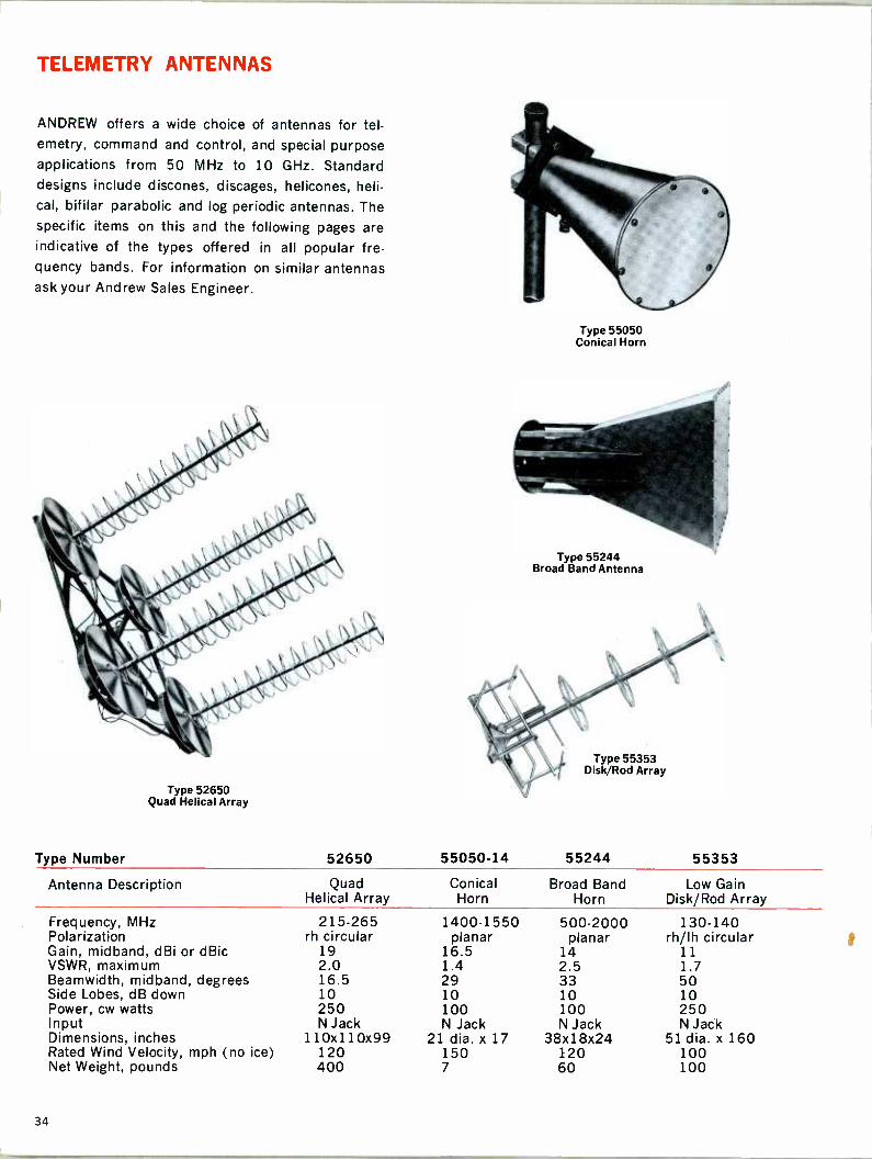
ANDREW offers a wide choice of antennas for tel- emetry, command and control, and special purpose applications from 50 MHz to 10 GHz. Standard designs include discones, discages, helicones, heli- cal, bifilar parabolic and log periodic antennas. The specific items on this and the following pages are indicative of the types offered in all popular fre- quency bands. For information on similar antennas ask your Andrew Sales Engineer.
Type 55050 Conical Horn
Type 55244 Broad Band Antenna
Type 55353 Disk/Rod Array
Type 52650 Quad Helical Array
Type Number 52650 55050-14 55244 55353
Antenna Description Quad Conical Broad Band Low Gain Helical Array Horn Horn Disk/Rod Array
Frequency, MHz 215-265 1400-1550 500-2000 130-140 Polarization rh circular planar planar rh/lh circular Gain, midband, dBi or dBic 19 16.5 14 11 VSWR, maximum 2.0 1.4 2.5 1.7 Beamwidth, midband, degrees 16.5 29 33 50 Side Lobes, dB down 10 10 10 10 Power, cw watts 250 100 100 250 Input N Jack N Jack N Jack N Jack Dimensions, inches 110x110x99 21 dia. x 17 38x18x24 51 dia. x 160 Rated Wind Velocity, mph (no ice) 120 150 120 100 Net Weight, pounds 400 7 60 100
34
TELEMETRY ANTENNAS
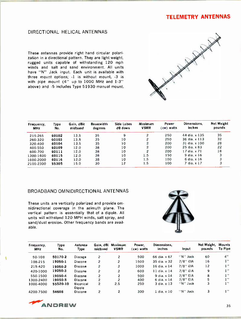
DIRECTIONAL HELICAL ANTENNAS
These antennas provide right hand circular polari- zation in a directional pattern. They are light weight, rugged units capable of withstanding 120 mph winds and salt and sand environment. All units have "N" Jack input. Each unit is available with three mount options; -1 is without mount, -3 is with pipe mount (4" up to 1000 MHz and 1-3" above) and -5 includes Type 51930 manual mount.
Frequency, MHz
Type No.
Gain, dBic mid band
Beamwidth degrees
Side Lobes dB down
Maximum VSWR
Power (cw) watts
Dimensions, inches
Net Weight pounds
215-265 60102 13.5 35 9 2 250 44 dia. x 135 35 260-320 60103 13.5 35 10 2 250 36 dia. x 113 32
320-400 60104 13.5 35 10 2 200 31 dia. x 100 28 400-550 60109 12.0 38 10 2 200 25 dia. x 83 22 600-700 60111 12.0 38 10 2 200 17 dia. x 71 18
1300.1600 60115 12.0 38 10 1.5 150 9 dia. x 16 3
1600-2000 60116 12.0 38 10 1.5 100 6 dia. x 16 3
2100-2300 55305 15.0 30 12 1.5 100 7 dia. x 17 3
BROADBAND OMNIDIRECTIONAL ANTENNAS
These units are vertically polarized and provide om- nidirectional coverage in the azimuth plane. The vertical pattern is essentially that of a dipole. All units will withstand 120 MPH winds, salt spray, and sand/dust erosion. Other frequency bands are avail- able.
Frequency, MHz
Type No.
Antenna Type
Gain, dBi midband
Maximum VSWR
Power, (cw) watts
Dimensions, inches Input
Net Weight, pounds
Mounts To Pipe
50-108 50170-2 Discage 2 2 500 66 dia. x 67 "N" Jack 60 4" 108-215 19050-1 Discone 2 2 1500 35 dia. x 32 7/8" EIA 16 1"
215-420 19050-2 Discone 2 2 1000 16 dia. x 14 7/8" EIA 12 1" 420-1000 19050-3 Discone 2 2 600 11 dia. x 14 7/8" EIA 9 1" 550-1500 19050-4 Discone 2 2 5Q0 9 dia. x 14 7/8" EIA 8 1"
1300-2400 19050-5 Discone 2 2 400 6 dia. x 14 7/8" EIA 5 1" 1000-4000 55520-10 Biconical 2 2.5 250 3 dia. x 13 "N" Jack 3 1"
Dipole 4200-7500 54608 Discone 2 2 300 1 dia. x 10 "N" Jack 3 1"
-41011".- ANDREW 35
TELEMETRY ANTENNAS
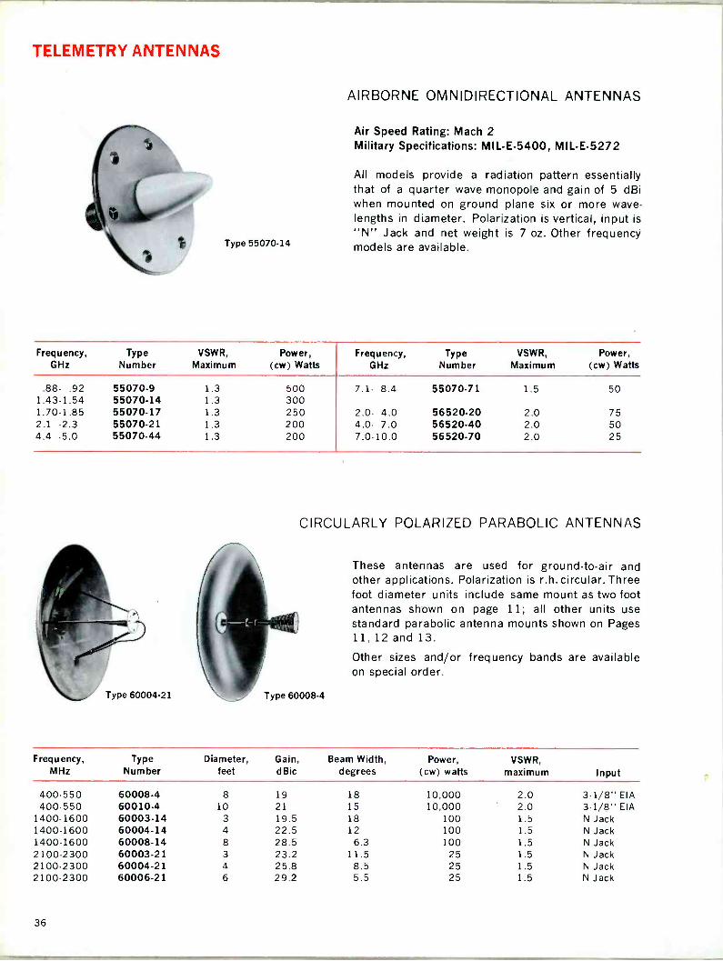
Type 55070-14
AIRBORNE OMNIDIRECTIONAL ANTENNAS
Air Speed Rating: Mach 2 Military Specifications: MIL -E-5400, MIL -E-5272
All models provide a radiation pattern essentially that of a quarter wave monopole and gain of 5 dBi when mounted on ground plane six or more wave- lengths in diameter. Polarization is vertical, input is "N" Jack and net weight is 7 oz. Other frequency models are available.
Frequency, GHz
Type Number
VSWR, Maximum
Power, (cw) Watts
Frequency, GHz
Type Number
VSWR, Maximum
Power, (cw) Watts
.88- .92 55070-9 1.3 500 7.1- 8.4 55070-71 1.5 50 1.43-1.54 55070-14 1.3 300 1.70-1.85 55070-17 1.3 250 2.0- 4.0 56520-20 2.0 75 2.1 -2.3 55070-21 1.3 200 4.0- 7.0 56520-40 2.0 50 4.4 -5.0 55070-44 1.3 200 7.0-10.0 56520-70 2.0 25
CIRCULARLY POLARIZED PARABOLIC ANTENNAS
These antennas are used for ground -to -air and other applications. Polarization is r.h. circular. Three foot diameter units include same mount as two foot antennas shown on page 11; all other units use standard parabolic antenna mounts shown on Pages 11,12 and 13.
Other sizes and/or frequency bands are available on special order.
Type 60004-21 \ % Type 60008-4
Frequency, MHz
Type Number
Diameter, feet
Gain, dBic
Beam Width, degrees
Power, (cw) watts
VSWR, maximum Input
400-550 60008-4 8 19 18 10,000 2.0 3-1/8" EIA 400-550 60010-4 10 21 15 10,000 2.0 3-1/8" EIA
1400-1600 60003-14 3 19.5 18 100 1.5 N Jack 1400-1600 60004-14 4 22.5 12 100 1.5 N Jack 1400-1600 60008-14 8 28.5 6.3 100 1.5 N Jack 2100-2300 60003-21 3 23.2 11.5 25 1.5 N Jack 2100-2300 60004-21 4 25.8 8.5 25 1.5 N Jack 2100-2300 60006.21 6 29.2 5.5 25 1.5 N Jack
36

TELEMETRY ANTENNAS
BROADBAND VHF DIRECTIONAL
Type 59135 is a log periodic antenna covering the 140-750 MHz band. The unit is fabricated of stain- less steel tubing for corrosion resistance and may be mounted for either vertical or horizontal polari- zation.
HIGH GAIN UHF OMNIDIRECTIONAL
Type 56090 and similar units are used in missile test ranges to transmit range timing signals. Polari- zation is vertical, horizontal pattern is circular with- in ± 0.2° and vertical pattern is 8.5° to half power points. The unit is 1.5 inches in diameter and 62 inches high.
CHARACTERISTICS
Type Number 59135 56090
Frequency, MHz 140-750 1725-1775 Gain, Mid -band dBi 10 9.5 VSWR, Maximum 3.0 1.5 Power, (cw) Watts 250 100 Input N Jack N Jack Rated Wind Velocity
mph, (no ice) 150 100
Net Weight, pounds 35 8
ANTENNA MOUNTS
Omnidirectional and certain directional antennas include pipe mounts, as indicated in the previous pages. These allow 360° azimuth adjustment. The 1.4-1.6 and 2.1-2.3 GHz antenna pipe mounts also provide ± 180° elevation adjustment.
The parabolic antennas in this section can be used with any of the standard mounts shown on pages 11, 12 and 13. These antennas and the helical arrays may also be used with any of the positioners shown on pages 40 to 43.
Type 51935, Portable Tripod, is a heavy duty model used for temporary or permanent installation. Height is 50 inches and net weight is 20 pounds.
Type 51930, Tilt Mount allows 360° azimuth ad- justment and 0° to 90° elevation adjustment and may be locked in position. Type 51930 Tilt Mount is
designed for use with Type 51935 Portable Tripod.
Type 59135 VHF Directional
Type 56090 UHF Omnidirectional
Type 51930 Tilt Mount
Type 51935 Tripod
(with antenna and tilt mount)
ANDREW 37
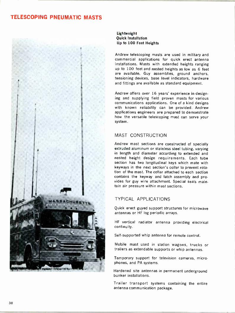
TELESCOPING PNEUMATIC MASTS
M,-.säACHuaE-r-re
Lightweight Quick Installation Up to 100 Feet Heights
Andrew telescoping masts are used in military and commercial applications for quick erect antenna installations. Masts with extended heights ranging up to 100 feet and nested heights as low as 6 feet are available. Guy assemblies, ground anchors, tensioning devices, base level indicators, hardware and fittings are available as standard equipment.
Andrew offers over 16 years' experience in design- ing and supplying field proven masts for various communications applications. One of a kind designs with known reliability can be provided. Andrew applications engineers are prepared to demonstrate how the versatile telescoping mast can serve your system.
MAST CONSTRUCTION
Andrew mast sections are constructed of specially extruded aluminum or stainless steel tubing, varying in length and diameter according to extended and nested height design requirements. Each tube section has two longitudinal keys which mate with keyways in the next section's collar to prevent rota- tion of the mast. The collar attached to each section contains the keyway and latch assembly and pro- vides for guy wire attachment. Special seals main- tain air pressure within mast sections.
TYPICAL APPLICATIONS
Quick erect guyed support structures for microwave antennas or HF log periodic arrays.
HF vertical radiator antenna providing electrical continuity.
Self -supported whip antenna for remote control.
Mobile mast used in station wagons, trucks or trailers as extendable supports or whip antennas.
Temporary support for television cameras, micro- phones, and PA systems.
Hardened site antennas in permanent underground bunker installations.
Trailer transport systems containing the entire antenna communication package.
38

TACTICAL TRANSPORTABLE MASTS
Mobile Mast System Illustrated at the right is a complete Andrew mobile microwave antenna system. Included in the trailer mounted package are:
100 ft. telescoping pneumatic mast complete with guy wires, guy stakes, and pneumatic cylinder to lift it into vertical position. El/Az positioner to fit on top of the mast.
Six foot 7 GHz parabolic antenna to fit on the positioner. Length of HELIAX elliptical waveguide to feed the antenna with control and power cables for the positioner as well as messenger cables extruded in the waveguide jacket.
Andrew dehydrator to pressurize the guide and raise the mast.
Gasoline driven motor generator set to power the dehydrator, the positioner, and the obstruc- tion lights.
This is indicative of the type of complete antenna system Andrew can furnish.
Manually Erected Transportable Mast Lightweight Aluminum Easy to Assemble Adaptable to Various Loadings Compact Design Meets Military Specifications
Andrew has designed a manually erected trans- portable mast, well suited for temporary installations or remote location applications. During erection the five foot aluminum tubular sec- tions are "breech loaded" into the erecting mecha- nism and manually raised by the lever arm as- sembly. The units include safety brake and locking ring arrangements and quick locking guy assemblies to facilitate installation.
APPLICATIONS Transportable Communications Systems-VHF or UHF-vehicular or airborne. Path testing for micro- wave system layout. Emergency service. Temporary radio systems.
SPECIFICATIONS 35 foot and 50 foot models have been manufac- tured. Erection time is on the order of 15 minutes for two men. Maximum horizontal thrust load at top is 320 pounds. Maximum vertical load is 70 pounds. Net weight of entire package is 115 pounds for 35 foot mast, 150 pounds for 50 foot. Your Andrew sales engineer can provide further details.
-.1011."ANDREW 39

38500 SERIES ANTENNA POSITIONERS
Type 38500 Positioner, 6 Foot Antenna With Mount And Counterweight Assembly
Type 38500 El/Az Positioner
Type 38501 Az Only Positioner
Type 38500 is a compact dual axis positioner. This lightweight unit is intended for use with antenna loads up to the equivalent of a 6 foot diameter solid paraboloid or up to an 8 foot mesh type para- boloid. Under rated load the positioner will with- stand 115 mph winds and will function within rated accuracies in 30 mph winds. Stow pins are not necessary under maximum rated loads. A mount adaptor is available to convert the standard pedestal for mounting on portable or telescoping masts.
Standard speed of rotation and elevation is one degree per second on 60 Hz power. Other speeds are available up to four degrees per second. Limit switches are included in azimuth/elevation drives. All positioners include 1:1 synchros for each axis. Position readout dials are provided on the control panel for each axis. All circuits are fused at the panel.
A control panel is included with each positioner. Control cable, antenna mounts, counterweights and pedestal extensions must be ordered separately.
The 38500 series pedestal is fully enclosed, gasket sealed and weather tight. The unit will withstand ex-
posure to sand, dust, rain and salt spray. Gear trains are enclosed in gear boxes with permanent lubrication.
The unit is available in several standard versions as outlined on the next page.
CHARACTERISTICS Type Number 38500 Function El/Az Input Voltage 120v, 60 Hz Power Requirements, watts 400 Maximum Vertical Load, pounds 1200 Wind Load, survival, mph* 115
Operational* 45 Readout Accuracy, degrees' ±1.0 Position Accuracy, degrees* ±0.5 Travel Limits, degrees
Elevation -10 to --i-190 Azimuth 400
Rated Speed, degrees/second (60 Hz) Azimuth 1.0 Elevation 1.0
Delivered Torque, ft. lbs. 120 Base Diameter, inches 24 Height, inches 21-1/4 Net Weight, pounds 235
With 6 foot solid parabolic antenna.
40
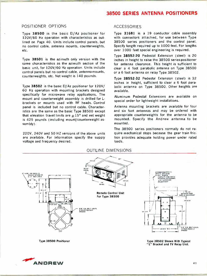
L , 1 LW
38500 SERIES ANTENNA POSITIONERS
POSITIONER OPTIONS
Type 38500 is the basic El/Az positioner for 120V/60 Hz operation with characteristics as out- lined on Page 40. Units include control panels, but no control cable, antenna mounts, counterweights, etc.
Type 38501 is the azimuth only version with the same characteristics as the azimuth section of the basic unit, for 120V/60 Hz operation. Units include control panels but no control cable, antenna mounts, counterweights, etc. Net weight is 140 pounds.
Type 38502 is the basic El/Az positioner for 120V/ 60 Hz operation with mounting brackets designed specifically for microwave relay applications. The mount and counterweight assembly is drilled for L -
brackets or mounts used with RF heads. Control panel is included but no control cable. Character- istics are the same as the basic Type 38500 except that elevation travel limits are ±15° and net weight is 425 pounds (including mount/counterweight as-
sembly).
220V, 240V and 50 HZ versions of the above units are available. For information specify the supply voltage and frequency desired.
ACCESSORIES
Type 31681 is a 19 conductor cable assembly with connectors attached, for use between Type 38500 series positioners and the control panel. Specify length required up to 1000 feet. For lengths over 1000 feet special engineering is required.
Type 38552-20 Pedestal Extension (steel) is 20 inches in height to raise the 38500 series positioner for antenna clearance. This height is sufficient to clear a 4 foot parabolic antenna on Type 38500 or a 6 foot antenna on relay Type 38502.
Type 38552-32 Pedestal Extension (steel) is 32 inches in height, sufficient to clear a 6 foot para- bolic antenna on Type 38500. Other heights are available.
Aluminum Pedestal Extensions are available on
special order for lightweight installations.
Antenna mounting brackets are available for four and six foot antennas and may be ordered with appropriate counterweights for the antenna to be mounted. Specify the Andrew antenna to be mounted.
The 38500 series positioners normally do not re- quire mechanical stops because the gear train fric- tion provides adequate holding power under rated loads.
OUTLINE DIMENSIONS
143/4"
8.3/4" PANEL
6-3/8" UNC-2B HOLES EQUALLY SPAC D ON
6.1/2" BOLT CIRCLE 19 7/8"
16
21.1/4"
5/8" DIA. BOLT HOLES 6 HOLES EQUALLY SPACED
Type 38500 Positioner
22
PANEL
105/8"
Remote Control Unit For Type 38500
21.1/
ACCOMMODATES4 FT.
086 FT. ANTENNA 4 FT. SHOWN (F086 FT. ADD 38552 PEDESTAL EXTENSION) .155 ELEVATION ADJUSTMENT
1" TO 12"
I
DEPENDS UPON TYPE OF EQUIPMENT
25-5/32"
- 22-5/8" B.C.-R.-1 24'
16 1/2'
/8" DIA. BOLT HOLES 6 HOLES EQUALLY SPACED
Type 38502 Shown With Typical "FL" Bracket and TV Relay Unit.
ANDREW 41

CUSTOM DESIGNED ANTENNA POSITIONERS 125 mph Heavy Duty Designs Antennas Up to 60 Feet Solid State Power Supplies Optional Servo Controls
Complete Installation of Rotatable 60 Foot Tropospheric Antenna
and Positioner
Inset: Positioner Being Lifted Into Position
15 Foot Telemetry Antenna and Positioner
Andrew single and dual axis positioners will accom- modate a wide selection of operating options and control systems.
All large positioners are custom designed to specific requirements using standard building blocks-hous- ings, motors, gear trains, antenna mounts, etc.
All positioners feature enclosed gear trains and motors. Large access doors, interlock switches and convenience outlets in positioner housings facilitate field inspection and maintenance. Heavy precision power gears assure long life and quiet operation. Motors, controlled by power amplifiers, assure re- latively constant torque outputs at all speeds and loads within rating. Electromechanical braking is supplied when necessary.
Units typically include electromanual controls with 1:1 synchros and readout indicators for each axis. Limit switches are used in both azimuth and eleva- tion.
Azimuth only positioners include standard electro - manual controls. Motors, protective devices and op- tional controls and equipment are similar to those available in dual axis positioners.
Shock absorbers may be provided in the elevation section. These shock absorbers, in conjunction with torque limitations on driving motors, preventdamage in the event of a circuit failure.
Standard options include servo controls, slip rings for continuous rotation, 36:1 position indicators, stow pins, rotary joints and dynamic braking.
Standard motors and counterweights are available for use with these positioners and any Andrew para- bolic or directional telemetry antenna.
Special antenna mounts and counterweights can be designed and fabricated to your specifications.
Base spacers are available to increase positioner heights and provide clearance for large antennas.
As these units are all custom designed, price and
delivery depend on individual requirements. Your Andrew Sales Engineer can submit a quotation to
your specifications.
42
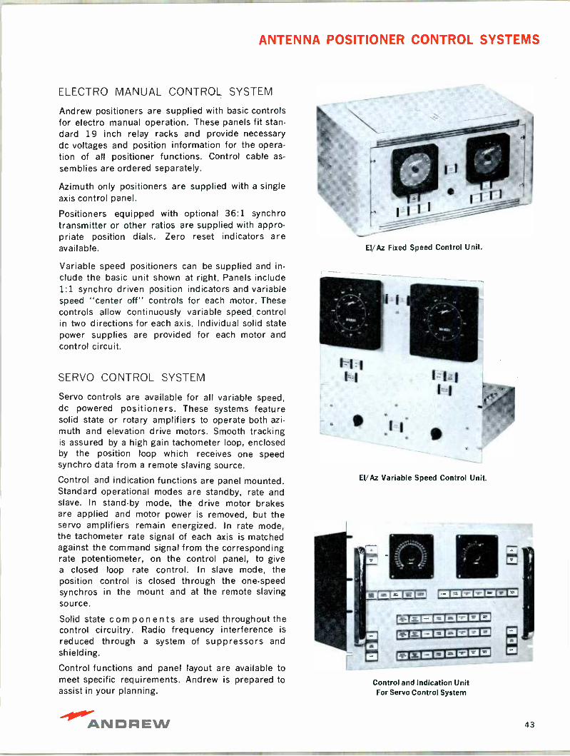
ANTENNA POSITIONER CONTROL SYSTEMS
ELECTRO MANUAL CONTROL SYSTEM
Andrew positioners are supplied with basic controls for electro manual operation. These panels fit stan- dard 19 inch relay racks and provide necessary dc voltages and position information for the opera- tion of all positioner functions. Control cable as-
semblies are ordered separately.
Azimuth only positioners are supplied with a single axis control panel.
Positioners equipped with optional 36:1 synchro transmitter or other ratios are supplied with appro- priate position dials. Zero reset indicators are available.
Variable speed positioners can be supplied and in- clude the basic unit shown at right. Panels include 1:1 synchro driven position indicators and variable speed "center off" controls for each motor. These controls allow continuously variable speed control in two directions for each axis. Individual solid state power supplies are provided for each motor and control circuit.
SERVO CONTROL SYSTEM
Servo controls are available for all variable speed, dc powered positioners. These systems feature solid state or rotary amplifiers to operate both azi- muth and elevation drive motors. Smooth tracking is assured by a high gain tachometer loop, enclosed by the position loop which receives one speed synchro data from a remote slaving source.
Control and indication functions are panel mounted. Standard operational modes are standby, rate and slave. In stand-by mode, the drive motor brakes are applied and motor power is removed, but the servo amplifiers remain energized. In rate mode, the tachometer rate signal of each axis is matched against the command signal from the corresponding rate potentiometer, on the control panel, to give a closed loop rate control. In slave mode, the position control is closed through the one -speed synchros in the mount and at the remote slaving source.
Solid state components are used throughout the control circuitry. Radio frequency interference is
reduced through a system of suppressors and shielding.
Control functions and panel layout are available to meet specific requirements. Andrew is prepared to assist in your planning.
EI/Az Fixed Speed Control Unit.
EI/Az Variable Speed Control Unit.
Control and Indication Unit For Servo Control System
-10."ANDREW 43

FIXED STATION ANTENNAS
INTRODUCTION
Andrew, a pioneer in the field, offers a wide selec- tion of fixed station antennas for the two-way com- munications industry. Many thousands of Andrew antennas are now in service throughout the world, many in continuous service for more than 15 years. Andrew antennas are designed, built and produc- tion tested with great care to ensure reliable field performance to system requirements. Andrew fixed station antennas include unipole, collinear array, corner reflector, and Yagi types in four frequency bands from 25 to 470 MHz.
The gains shown for antennas are given in dBd (Gain in decibels relative to a half wave dipole).
All antennas have a 50 ohm nominal input imped- ance.
Windload ratings are shown for all antennas. Thrust is indicated in pounds at 87 mph (30 psf) in ac-
cordance with EIA standards.
Unless otherwise indicated, a dc path to ground is
provided for lightning protection.
Certain antennas require separate mountingclamps. Clamps are illustrated and described on page 50.
Horizontal Radiation Pattern
Omnidirectional Unipole Antenna 25-148 MHz
Type 900C
The Andrew unipole antenna has been one of the more popular fixed station antennas for many years. It provides omnidirectional coverage at minimum cost. For directional coverage see the cardioid uni - pole antenna on opposite page.
CHARACTERISTICS Type Number 900C
Frequency, MHz 25-148 Gain, dBd 0 VSWR, maximum 1.5 Power Rating, watts 700 Termination, jack (female) UHF Survival Wind Velocity, mph 100 Thrust at 87 mph, pounds 46 Mounting Clamps: " For
round member tower, order 29291-3 angular member tower, order 14672-3
'See Page 50
ORDERING INFORMATION
Omnidirectional Unipole Antenna
Type Number
Frequency MHz
Net Weight Pounds
900C-0 25-30 28 900C-1 30-44 24 900C-2 44-54 20 900C-3 72-76 14 900C-4 108-148 10
44

30-50 MHz Cardioid Unipole Antenna
The cardioid unipole provides gain over a 180 de- gree horizontal sector. This antenna is ideally suited for service along city or state boundaries, shorelines or back to back with other services.
FIXED STATION ANTENNAS 148-174 MHz Omnidirectional Antenna
Type 925A
The high band unipole is an economical antenna for omnidirectional coverage when high gain is not re-
quired. For omnidirectional gain antennas, see page 46.
CHARACTERISTICS
Type Number 920
Frequency, MHz 30-50 Gain, dBd 3.0 Front to Back Ratio, minimum, dB 15.0 VSWR, maximum 1.5 Termination, jack (female) UHF Power Rating, watts 700 Survival Wind Velocity, mph 87 Thrust at 87 mph, pounds 87 Mounting Clamps:* For
round member tower, order 29291-3 angular member tower, order 14672-3
*See Page 50
ORDERING INFORMATION
Cardioid Unipole Antenna
Type Number
Frequency MHz
Net Weight Pounds
920E-1 30.36 57 920E-2 36-42 46 920E-3 42-50 42
High Band Omnidirectional Antenna 925A 146-174 7
925A
148-174 0
2.0 UHF 500 125
18
21208
Horizontal Radiation Patterns
--- TYPE 920E
270°
o° +5 TYPE 925A
-10
+5 180°
90°
ANDREW 45
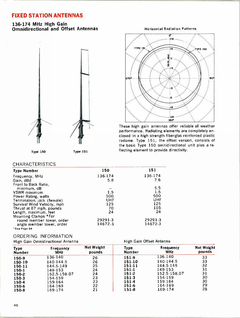
FIXED STATION ANTENNAS
136-174 MHz High Gain Omnidirectional and Offset Antennas
Type 150
CHARACTERISTICS
Type 151
Horizontal Radiation Patterns
These high gain antennas offer reliable all weather performance. Radiating elements are completely en- closed in a high strength fiberglas reinforced plastic radome. Type 151, the offset version, consists of the basic Type 150 omnidirectional unit plus a re- flecting element to provide directivity.
Type Number 150 151
Frequency, MHz 136-174 136-174 Gain, dBd 5.8 7.6 Front to Back Ratio,
minimum, dB - 5.5 VSWR maximum 1.5 1.5 Power Rating, watts 500 500 Termination, jack (female) UHF UHF Survival Wind Velocity, mph 125 125 Thrust at 87 mph, pounds 70 105 Length, maximum, feet 24 24 Mounting Clamps '`For
round member tower, order 29291-3 29291-3 angle member tower, order 14672-3 14672-3
'See Page 50
ORDERING INFORMATION High Gain Omnidirectional Antenna High Gain Offset Antenna
Type Number
Frequency MHz
Net Weight pounds
Type Number
Frequency MHz
Net Weight pounds
150-9 136-140 26 151-9 136-140 33 150-10 140-144.5 26 151-10 140-144.5 33 150-11 144.5-149 25 151-11 144.5-149 -32 150-1 149-153 24 151-1 149-153 31 150-2 152.5-158.07 24 151-2 152.5-158.07 31 150-3 154-159 23 151-3 154-159 30 150-4 159-164 23 151-4 159-164 30 150-6 164-169 22 151-6 164-169 29 150-8 169-174 21 151-8 169-174 28
46
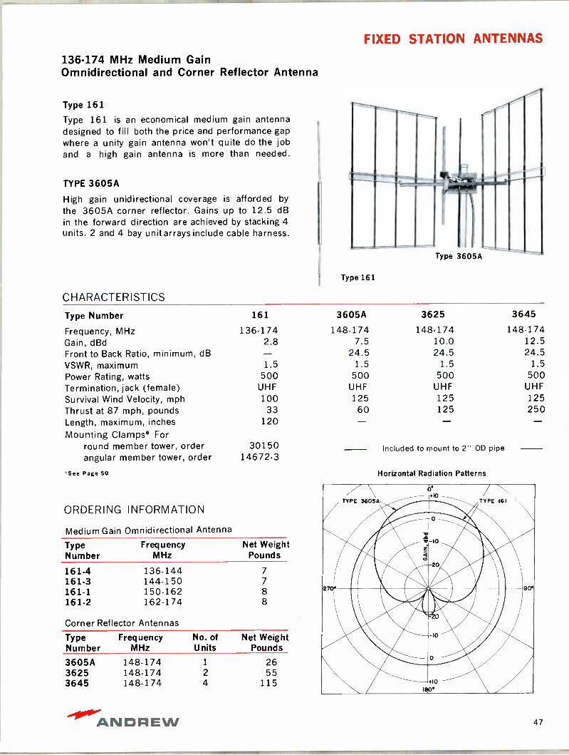
FIXED STATION ANTENNAS
136-174 MHz Medium Gain Omnidirectional and Corner Reflector Antenna
Type 161
Type 161 is an economical medium gain antenna designed to fill both the price and performance gap where a unity gain antenna won't quite do the job and a high gain antenna is more than needed.
TYPE 3605A
High gain unidirectional coverage is afforded by
the 3605A corner reflector. Gains up to 12.5 dB in the forward direction are achieved by stacking 4 units. 2 and 4 bay unit arrays include cable harness.
Type 161
CHARACTERISTICS
Type 3605A
Type Number 161
Frequency, MHz 136-174 Gain, dBd 2.8 Front to Back Ratio, minimum, dB VSWR, maximum 1.5 Power Rating, watts 500 Termination, jack (female) UHF
Survival Wind Velocity, mph 100 Thrust at 87 mph, pounds 33 Length, maximum, inches 120 Mounting Clamps* For
round member tower, order 30150 angular member tower, order 14672-3
See Page 50
ORDERING INFORMATION
Medium Gain Omnidirectional Antenna
Type Frequency Net Weight Number MHz Pounds
161-4 136-144 7
161-3 144-150 7
161-1 150-162 8 161-2 162-174 8
Corner Reflector Antennas
Type Frequency No. of Net Weight Number MHz Units Pounds
3605A 148.174 1 26 3625 148-174 2 55 3645 148-174 4 115
3605A
148-174 7.5
24.5 1.5
500 UHF 125
60
3625 3645
148-174 148-174 10.0 12.5 24.5 24.5
1.5 1.5 500 500
UHF UHF 125 125 125 250
Included to mount to 2" OD pipe
Horizontal Radiation Patterns
ANDREW 47
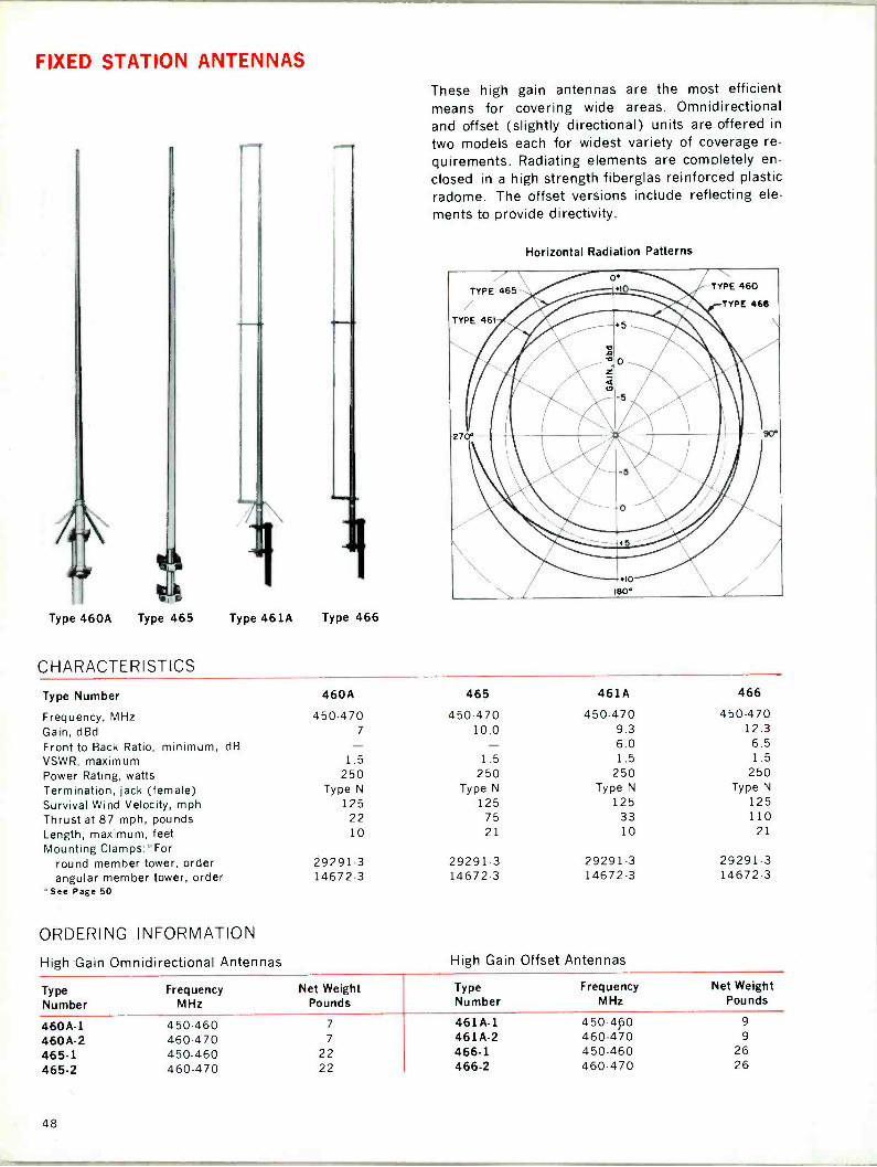
FIXED STATION ANTENNAS
Type 460A Type 465
CHARACTERISTICS
-11
Type 461A Type 466
These high gain antennas are the most efficient means for covering wide areas. Omnidirectional and offset (slightly directional) units are offered in
two models each for widest variety of coverage re-
quirements. Radiating elements are completely en-
closed in a high strength fiberglas reinforced plastic radome. The offset versions include reflecting ele-
ments to provide directivity.
Horizontal Radiation Patterns
TYPE 465
TYPE 461
TYPE 460
TYPE 466
Type Number 460A 465 461A 466
Frequency, MHz 450-470 450-470 450-470 450-470 Gain, dBd 7 10.0 9.3 12.3
Front to Back Ratio, minimum, dB - - 6.0 6.5 VSWR, maximum 1.5 1.5 1.5 1.5
Power Rating, watts 250 250 250 250 Termination, jack (female) Type N Type N Type N Type N
Survival Wind Velocity, mph 125 125 125 125
Thrust at 87 mph, pounds 22 75 33 110 Length, maximum, feet 10 21 10 21
Mounting Clamps:"For round member tower, order 29291-3 29291-3 29291-3 29291-3 angular member tower, order 14672-3 14672-3 14672-3 14672-3
"See Page 50
ORDERING INFORMATION
High Gain Omnidirectional Antennas High Gain Offset Antennas
Type Number
Frequency MHz
Net Weight Pounds
Type Number
Frequency MHz
Net Weight Pounds
460A-1 450-460 7 461A-1 450-4¢0 9
460 A-2 460-470 7 461A-2 460-470 9
465-1 450-460 22 466-1 450-460 26
465-2 460-470 22 466-2 460-470 26
48
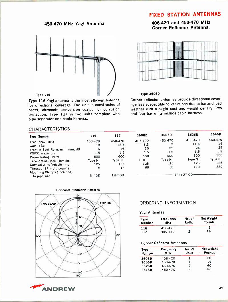
450-470 MHz Yagi Antenna
Type 116 Yagi antenna is the most efficient antenna for directional coverage. The unit is constructed of
brass, chromate conversion coated for corrosion protection. Type 117 is two units complete with pipe separator and cable harness.
CHARACTERISTICS
FIXED STATION ANTENNAS
406-420 and 450-470 MHz Corner Reflector Antenna.
Type 3606D
Corner reflector antennas provide directional cover-
age less susceptible to variations due to ice and bad
weather with a slight cost and weight penalty. Two
and four bay units include cable harness.
Type Number 116 117 3608D 3606D 3626D 3646D
Frequency, MHz Gain, dBd Front to Back Ratio, minimum, dB VSWR, maximum
450-470 10 16 1.5
450-470 12.5
16 1.5
406-420 8.5 20 1.5
450-470 9
25 1.5
450-470 11.5
25 1.5
450-470 14 25 1.5
Power Rating, watts 600 600 500 500 500 500
Termination, jack (female) Survival Wind Velocity, mph
Type N
125 Type N
125 UHF
125 Type N
125 Type N
125 Type N
125
Thrust at 87 mph, pounds 8 17 60 58 110 220
Mounting Clamps (Included) 3/4" to pipe size 3/4" OD 11/2" OD to 2" OD
Horizontal Radiation Patterns
ORDERING INFORMATION
Yagi Antennas
Type Frequency Number MHz
No. of Net Weight Units Pounds
116 450-470 1 5
117 450-470 2 14
Corner Reflector Antennas
Type Number
Frequency MHz
No. of Units
Net Weight Pounds
3608D 406-420 20 3606D 450-470 19
3626D 450-470 2 40 3646D 450-470 4 80
ANDREW 49

FIXED STATION ANTENNA ACCESSORIES
Type 20898
Type 15681
Type 21208
Type 14672-3
! pve .
1
Type 29291-3
Type 31553
trr
MOUNTING CLAMPS Check the antenna specifications to determine which models require separate mounting hardware. For antennas requiring mounting hardware, Andrew offers a wide selection of pipe and tower clamps constructed of heavy duty galvanized steel for maxi- mum strength and durability.
Set of two clamps for mounting Type 920E card- ioids to round pipe members from 3/4" -3" OD
Type 20898
Set of two clamps for mounting 925A series Unipoles to 1" OD pipe Type 21208
Set of two clamps for attachment of antenna to any round member from 3/4" -3" OD. Type 15681
Set of two clamps for attachment of antenna to angle type members up to 7/8" thick without drilling Type 14672-3
Set of two clamps for attachment of antenna to any round member from 1" -3" OD. Type 29291-3
Set of two clamps for attachment of Type 161 series antennas to 1 3/4" OD pipe (not illustrated) . . . .
Type 30150
SIDE MOUNT KITS Kits are provided with bracket, clamps and hard- ware necessary for mounting antennas to side of tower. Mounting bracket and clamps are heavy duty galvanized steel.
Side Mount Kit is designed for mounting Type 150, 151, 465, and 466 antennas. Includes high wind - load sway brace Type 31553
Side Mount Kit designed for mounting Type 460, 461, and 161.. Type31554
JUMPER CABLES
6 feet of 1/2" Foam HELIAX coaxial cable with 2 type N plugs Type 25832
6 feet of 1/2" Foam HELIAX coaxial cable with 2 type UHF plugs Type 25833
6 feet of 1/2" Foam HELIAX coaxial cable with 1
each type UHF and type N plugs . . . . Type 25834
4 feet of RG8U with 2 type N plugs. Type 16253-21
4 feet of RG8U with 2 type UHF plugs Type 16253-23
4 feet of RG8U with 1 each type UHF and type N
plugs Type 16253-24
50
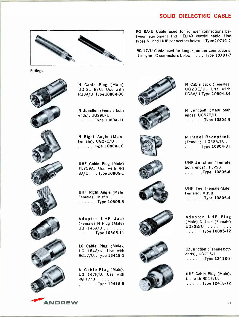
SOLID DIELECTRIC CABLE
Fittings
N Cable Plug (Male) UG 21 E/U. Use with RG8A/U. Type 10804-36
N Junction (Female both ends), UG29B/U.
Type 10804-11
N Right Angle (Male - Female), UG27C/U . . .
Type 10804-10
UHF Cable Plug (Male) PL259A. Use with RG
8A/U. . . Type 10805-1
UHF Right Angle (Male - Female), M359
Type 10805-5
Adaptor UHF Jack (Female) N Plug (Male) UG 146A/U
Type 10805-11
LC Cable Plug (Male), UG 154A/U. Use with RG17/U.. Type 12418-1
N Cable Plug (Male), UG 167F/U. Use with RG 17/U
Type 12418-5
RG 8A/U Cable used for jumper connections be-
tween equipment and HELIAX coaxial cable. Use
types N and UHF connectors below. . Type 10791-1
RG 17/U Cable used for longer jumper connections. Use type LC connectors below . . . . Type 10791-7
N Cable Jack (Female), UG23E/U. Use with RG8A/U.Type 10804-34
N Junction (Male both ends), UG57B/U.
Type 10804-9
N Panel Receptacle (Female). UG58A/U. . .
Type 10804-31
UHF Junction (Female both ends), PL258. . .
Type 10805-6
UHF Tee (Female -Male - Female), M358.
Type 10805-4
Adaptor UHF Plug (Male) N Jack (Female) UG83B/U
Type 10805-12
LC Junction (Female both ends), UG215/U.
Type 12418-3
UHF Cable Plug (Male). Use with RG17/U.
Type 12418-12
ANDREW 51
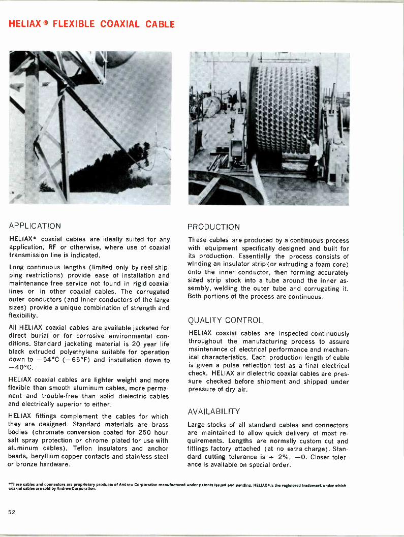
HELIAX ® FLEXIBLE COAXIAL CABLE
APPLICATION
HELIAX* coaxial cables are ideally suited for any application, RF or otherwise, where use of coaxial transmission line is indicated.
Long continuous lengths (limited only by reel ship- ping restrictions) provide ease of installation and maintenance free service not found in rigid coaxial lines or in other coaxial cables. The corrugated outer conductors (and inner conductors of the large sizes) provide a unique combination of strength and flexibility.
All HELIAX coaxial cables are available jacketed for direct burial or for corrosive environmental con- ditions. Standard jacketing material is 20 year life black extruded polyethylene suitable for operation down to -54°C (-65°F) and installation down to -40°C.
HELIAX coaxial cables are lighter weight and more flexible than smooth aluminum cables, more perma- nent and trouble -free than solid dielectric cables and electrically superior to either.
HELIAX fittings complement the cables for which they are designed. Standard materials are brass bodies (chromate conversion coated for 250 hour salt spray protection or chrome plated for use with aluminum cables), Teflon insulators and anchor beads, beryllium copper contacts and stainless steel or bronze hardware.
PRODUCTION
These cables are produced by a continuous process with equipment specifically designed and built for its production. Essentially the process consists of winding an insulator strip (or extruding a foam core) onto the inner conductor, then forming accurately sized strip stock into a tube around the inner as- sembly, welding the outer tube and corrugating it. Both portions of the process are continuous.
QUALITY CONTROL
HELIAX coaxial cables are inspected continuously throughout the manufacturing process to assure maintenance of electrical performance and mechan- ical characteristics. Each production length of cable is given a pulse reflection test as a final electrical check. HELIAX air dielectric coaxial cables are pres- sure checked before shipment and shipped under pressure of dry air.
AVAILABILITY
Large stocks of all standard cables and connectors are maintained to allow quick delivery of most re- quirements. Lengths are normally custom cut and fittings factory attached (at no extra charge). Stan- dard cutting tolerance is + 2%, -0. Closer toler- ance is available on special order.
*These cables and connectors are proprietary products of Andrew Corporation manufactured under patents issued and pending. HELIAX® is the registered trademark under which coaxial cables are sold by Andrew Corporation.
52
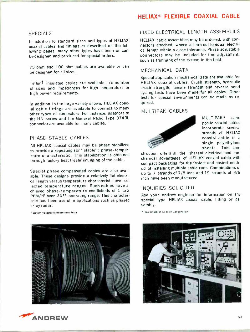
HELIAX® FLEXIBLE COAXIAL CABLE
SPECIALS
In addition to standard sizes and types of HELIAX
coaxial cables and fittings as described on the fol- lowing pages, many other types have been or can
be designed and produced for special orders.
75 ohm and 100 ohm cables are available or can
be designed for all sizes.
Teflont insulated cables are available in a number of sizes and impedances for high temperature or high power requirements.
In addition to the large variety shown, HELIAX coax-
ial cable fittings are available to connect to many
other types of connectors. For instance, adaptors to
the HN series and the General Radio Type 874BL connector are available for many cables.
PHASE STABLE CABLES
All HELIAX coaxial cables may be phase stabilized to provide a repeating (or "stable") phase -temper- ature characteristic. This stabilization is obtained through factory heat treatment aging of the cable.
Special phase compensated cables are also avail- able. These designs provide a relatively flat electri- cal length versus temperature characteristic over se-
lected temperature ranges. Such cables have a-
chieved phase -temperature coefficients of 1 to 2
PPM/°F over 30°F operating range. This character- istic has been useful in applications such as phased array radar.
t DuPont Polytetrafluoroethylene Resin
FIXED ELECTRICAL LENGTH ASSEMBLIES
HELIAX cable assemblies may be ordered, with con-
nectors attached, where all are cut to equal electri-
cal length within a close tolerance. Phase adjustable connectors may be included for fine adjustment, such as trimming of the system in the field.
MECHANICAL DATA
Special application mechanical data are available for HELIAX coaxial cables. Crush strength, hydraulic crush strength, tensile strength and reverse bend
cycling tests have been made for all cables. Other tests for special environments can be made as re-
quired.
MULTIPAK CABLES MULTIPAK* com- posite coaxial cables incorporate several strands of HELIAX coaxial cable in a
single polyethylene sheath. This con-
struction offers all the inherent electrical and me-
chanical advantages of HELIAX coaxial cable with
compact packaging for the fastest and easiest meth-
od of installing multiple cable runs. Combinations of
up to 7 strands of 7/8 inch and 19 strands of 3/8 inch have been manufactured.
INQUIRIES SOLICITED Ask your Andrew engineer for information on any
special type HELIAX coaxial cable, fitting or as-
sembly.
°Trademark of Andrew Corporation
ANDREW 53

1/2" SUPERFLEXIBLE HELIAX® CABLE
CABLE TYPE
FSJ4-50
CHARACTERISTICS
This superflexible HELIAX foam dielectric coaxial cable offers the flexibility of braided solid dielectric cable with the lower attenuation and superior shield- ing characteristics of a continuous solid sheath cop- per outer conductor.
The braided inner conductor and deeply corrugated seam welded copper outer conductor permit easy bending on small radii and continuous flexing with no impairment of electrical efficiency. Attenuation is 35% less than RG213/U (RG8A/U). A polyethylene jacket is standard for abrasion protection.
This superflexible cable is ideal for short length ap- plications, such as patch cords and jumper cables, where repeated flexing is a prime consideration, and in long lengths for temporary tactical or restora- tion systems where cable must be handled quickly and easily to provide reliable connections.
Fittings are easily assembled to cable with simple hand tools.
Electrical Mechanical Impedance, ohms 50 Outer Conductor O.D. inches .478 Maximum Frequency, GHz' 10.2 Diameter, over jacket, inches .518 Velocity, percent 78 Minimum Bending Radius, inches 1.25 Peak Power Rating, kw 7.5 Cable Weight Attenuation See Page 90 Jacketed, pounds per foot .156 Average Power Rating See Page 91
For applications above 1GHz, consult your Andrew Sales Engineer.
SHIPPING INFORMATION (Domestic)
Length, Feet Package Size, Inches Tare Weight, Lbs.
to 150 Carton 31 x 31 x 3 5 151 to 400 Carton 48 x 48 x 6 15 401 to 2000 Disposable reel 48 dia x 24w 94
COMPONENTS
N Plug (Male) Mates with UG23. Type 36723
General Radio Plug Mates with GR 874 . . .
Type 36722
54

' 1lMnAEL`!eIM I I sl
1/4" AND 3/8" FOAM DIELECTRIC HELIAX® CABLES
These small HELIAX cables are ideal for all low
power coaxial cable applications, particularly where space is at a premium.
The corrugated copper outer conductors and foamed polyethylene dielectrics result in cables with com-
binations of strength, corrosion resistance, flexibility and electrical efficiency not found in smooth wall aluminum or solid dielectric cables.
The "solid" outer conductors assure noise -free char- acteristics which will not deteriorate with time.
CABLE TYPES Nominal Size 1/4" Type FH1-50 Jacketed Type FHJ 1-50
CHARACTERISTICS
3/8" FH2-50A FHJ2-50A
Electrical Mechanical Nominal Size 1/4" 3/8" Nominal Size 1/4" 3/8" Impedance, ohms 50 50 Outer Conductor O.D., inches .250 .375 Maximum Frequency, GHz* 18 12 Diameter, over jacket, inches .290 .435 Velocity, percent 79 79 Minimum Bending Radius, inches 2.5 3.75 Peak Power Rating, kw 5 8 Cable Weight, pounds per foot Attenuation See page 90 Unjacketed .05 .10 Average Power Rating See page 91 Jacketed .06 .12
For applications above 1 GHz, consult your Andrew Sales Engineer.
SHIPPING INFORMATION (Domestic) Length, Feet
1/4" Cable to 300 301 to 600 601 to 3500 3501 to 7000
COMPONENTS
3/8" Cable to 250 251 to 500 501 to 2000 2001 to 3500
Package Carton Carton Disposable reel Disposable reel
UHF Jack (Female) Mates with PL259A 1/4" Cable .. Type 41U 3/8" Cable . . Type 42U
UHF Plug (Male) Mates with S0 -239A 1/4" Cable .. Type 41P 3/8" Cable .. Type 42P
TNC Plug (Male) Mates with TNC female 1/4" Cable . Type 41WT 3/8" Cable . Type 42WT
Size, Inches 31 x 31 x 3
48 x 48 x 6
48 dia. x 24w 72 dia. x 31w
Tare Weight, Lbs. 5
15 94
315
N Jack (Female) Mates with UG21 1/4" Cable .. Type 41N 3/8" Cable .. Type 42N
N Plug (Male) Mates with UG23 1/4" Cable .. Type 41W 3/8" Cable .. Type 42W
End Terminal Adaptor Type N jack. Use with Type 41W or 42W on Cable . . . Type 13212-2
ANDREW 55

1/2" FOAM DIELECTRIC HELIAX® CABLE
CABLE TYPES
Outer Conductor Impedance, ohms Andrew Type Jacketed Andrew Type Military Number
CHARACTERISTICS
This foam HELIAX coaxial cable is designed for fixed station antenna use and other low power ap- plications.
The corrugated outer conductor and foam dielectric provide a combination of strength, flexibility and ef- ficiency not available in semiflexible smooth wall or solid dielectric cables.
The cable is available with either copper or alumi- num corrugated outer conductor as shown in the table below. The aluminum version (jacketed only) retains most of the strength and flexibility of the copper cable with savings in weight and cost at a
degradation of only 12% in attenuation and 10% in average power rating. The basic electrical and mechanical data shown apply to both copper and aluminum versions.
Copper 50
FH4-50B FHJ4-50B RG366/U
Copper 75
FH4-75 FHJ4-75
Aluminum 50
FLJ4 - 50B
Electrical Mechanical
Impedance, ohms 50 75 Outer Conductor 0.D. inches .540 Maximum Frequency, GHz° 8.1 9.1 Diameter, over jacket, inches .620 Velocity, percent 79 79 Minimum Bending Radius, inches 5 Peak Power Rating, kw 19 12.7 Cable Weight, pounds per foot Attenuation See pages 90 & 92 Unjacketed, copper .125 Average Power Rating See pages 91 & 93 Jacketed, copper .185
For applications above 1GHz, consult your Andrew Sales Engineer. Jacketed, aluminum .135
SHIPPING INFORMATION (Domestic)
Length, Feet Package Size, Inches Tare Weight, Lbs.
to 150 Carton 31 x 31 x 3 5
151 to 400 Carton 48 x 48 x 6 15 401 to 2000 Disposable reel 48 dia. x 24 w 94 2001 to 3000 Disposable reel 72 dia. x 31 w 315
The listing of military nomenclature and/or Federal Stock Numbers with Andrew part numbers is for reference only.
56

1/2" COMPONENTS
All flanged items include inner connector, "0" ring, silicone grease and hardware. Components may be used for aluminum and copper cables unless otherwise noted. Type N and UHF 75 ohm connectors have 50 ohm pins in mating sections.
INNER TEFLON CONDUCTOR BEAD
OUTER CLAMPING BODY BODY
Typical Connector Construction
7/8" EIA Flange Not pressure tight. For copper cable. 50 ohm ....Type 44AR For aluminum cable. 50 ohm ..Type 44AR-3
Splice For copper cable. 50 ohm .... Type 44AZ
LC Plug (Male) mates with UG 352. For copper cable. 50 ohm . . .Type 44AM
LC Jack (Female) mates with UG 154. For copper cable. 50 ohm .... Type 44AL.
UHF Plug (Male) mates with 30239A. For copper cable. 50 ohm .... Type 44AP For aluminum cable. 50 ohm .. Type 44AP-3
UHF Jack (Female) mates with PL259A. For copper cable. 50 ohm . . .Type 44AÚ 75 ohm .Type 44AÚ-75 For aluminum cable. 50 ohm . . Type 44AU-3
N Plug (Male) mates with UG23. For copper cable. 50 ohm .... Type 44AW 75 ohm .. Type 44AW-75 For aluminum cable. 50 ohm . . Type 44AW-3
N Jack (Female) mates with UG 21. For copper cable. 50 ohm .... Type 44AN 75 ohm .. Type 44AN-75 For aluminum cable. 50 ohm .. Type 44AN-3
End Terminal for strap connection to center con- ductor. For copper cable. 50 ohm .... Type 44AT
HN Plug (Male) mates with UG60. For copper cable. 50 ohm .... Type 44AJ
EIA Gas Barrier use when connecting Type 44AR to pressurized line. 50 ohm ... Type 1260A
ANDREW 57
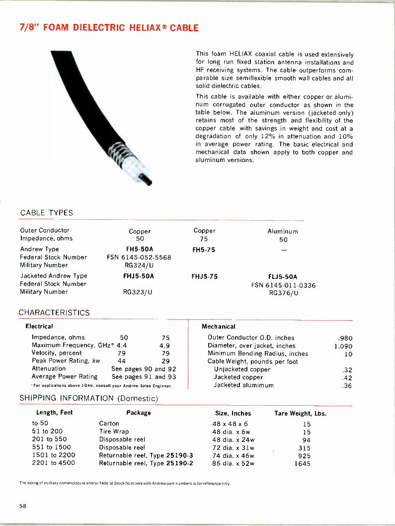
7/8" FOAM DIELECTRIC HELIAX® CABLE
CABLE TYPES
Outer Conductor Impedance, ohms
Andrew Type Federal Stock Number Military Number
Jacketed Andrew Type Federal Stock Number Military Number
CHARACTERISTICS
This foam HELIAX coaxial cable is used extensively for long run fixed station antenna installations and HF receiving systems. The cable outperforms com- parable size semiflexible smooth wall cables and all solid dielectric cables.
This cable is available with either copper or alumi- num corrugated outer conductor as shown in the table below. The aluminum version (jacketed only) retains most of the strength and flexibility of the copper cable with savings in weight and cost at a
degradation of only 12% in attenuation and 10% in average power rating. The basic electrical and mechanical data shown apply to both copper and aluminum versions.
Copper 50
FH5-50A FSN 6145-052-5568
RG324/U
FHJ 5-50A
RG323/U
Copper 75
FH5-75
FHJ5-75
Aluminum 50
FLJ5-50A FSN 6145-011-0336
RG376/U
Electrical
Impedance, ohms 50 75 Maximum Frequency, GHz* 4.4 4.9
Mechanical
Outer Conductor O.D. inches Diameter, over jacket, inches
.980 1.090
Velocity, percent 79 79 Minimum Bending Radius, inches 10 Peak Power Rating, kw 44 29 Cable Weight, pounds per foot Attenuation See pages 90 and 92 Unjacketed copper .32 Average Power Rating See pages 91 and 93 Jacketed copper .42 For applications above 1GHz, consult your Andrew Sales Engineer. Jacketed alumimum .36
SHIPPING INFORMATION (Domestic)
Length, Feet Package Size, Inches Tare Weight, Lbs.
to 50 Carton 48 x 48 x 6 15 51 to 200 Tire Wrap 48 dia. x 6w 15 201 to 550 Disposable reel 48 dia. x 24w 94 551 to 1500 Disposable reel 72 dia. x 31w 315 1501 to 2200 Returnable reel, Type 25190-3 74 dia. x 46w 925 2201 to 4500 Returnable reel, Type 25190-2 86 dia. x 52w 1645
The listing of military nomenclature and/or Federal Stock Numbers with Andrew part numbers is for reference only.
58
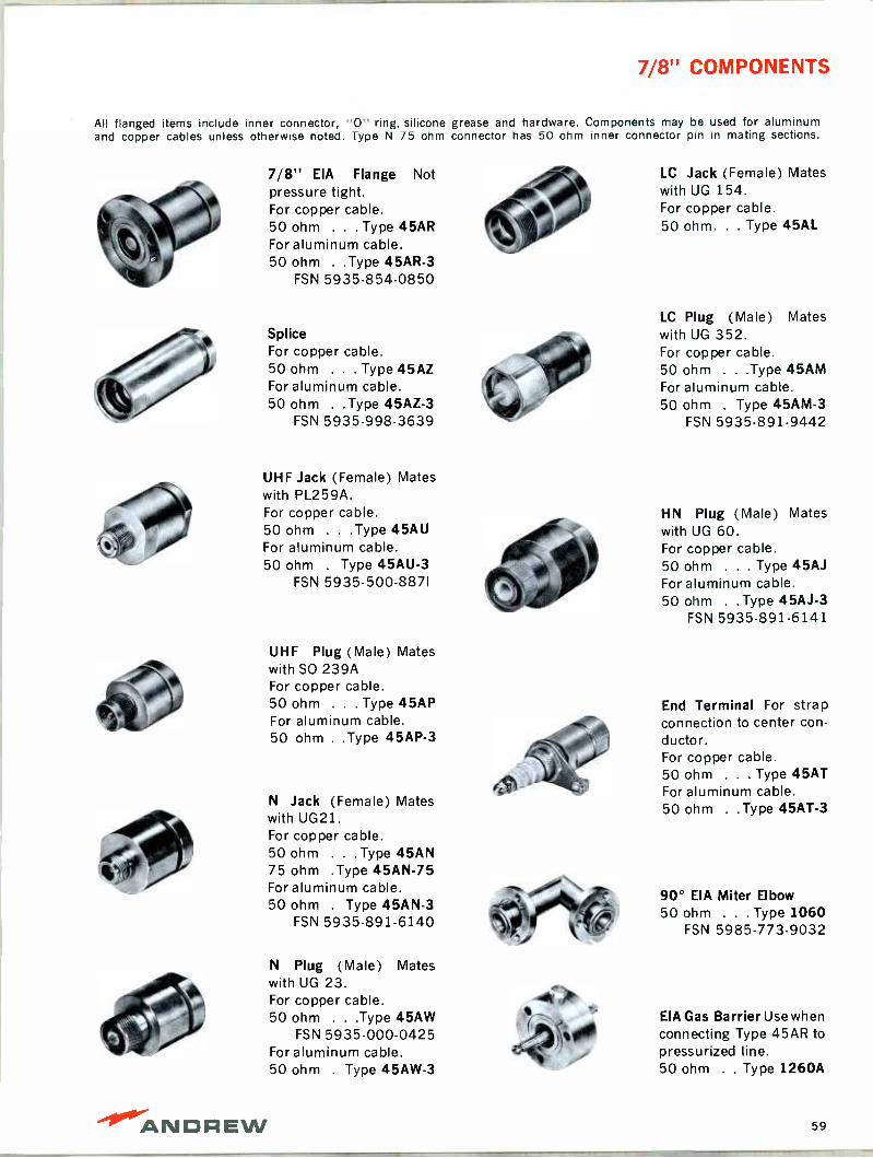
7/8" COMPONENTS
All flanged items include inner connector, "0" ring, silicone grease and hardware. Components may be used for aluminum and copper cables unless otherwise noted. Type N 75 ohm connector has 50 ohm inner connector pin in mating sections.
7/8" EIA Flange Not pressure tight. For copper cable. 50 ohm . . . Type 45AR For aluminum cable. 50 ohm . .Type 45AR-3
FSN 5935-854-0850
Splice For copper cable. 50 ohm . . . Type 45AZ For aluminum cable. 50 ohm . .Type 45AZ-3
FSN 5935-998-3639
UHF Jack (Female) Mates with PL259A. For copper cable. 50 ohm . . .Type 45AU For aluminum cable. 50 ohm . Type 45AU-3
FSN 5935-500-8871
UHF Plug (Male) Mates with SO 239A For copper cable. 50 ohm . . . Type 45AP For aluminum cable. 50 ohm . .Type 45AP-3
N Jack (Female) Mates with UG21. For copper cable. 50 ohm . . .Type 45AN 75 ohm .Type 45AN-75 For aluminum cable. 50 ohm . Type 45AN-3
FSN 5935.891-6140
N Plug (Male) Mates with UG 23. For copper cable. 50 ohm . . .Type 45AW
FSN 5935-000-0425 For aluminum cable. 50 ohm . Type 45AW-3
LC Jack (Female) Mates with UG 154. For copper cable. 50 ohm. . . Type 45AL
LC Plug (Male) Mates with UG 352. For copper cable. 50 ohm . . .Type 45AM For aluminum cable. 50 ohm . Type 45AM-3
FSN 5935.891-9442
HN Plug (Male) Mates with UG 60. For copper cable. 50 ohm . . . Type 45AJ For aluminum cable. 50 ohm . . Type 45AJ-3
FSN 5935-891-6141
End Terminal For strap connection to center con- ductor. For copper cable. 50 ohm . . . Type 45AT For aluminum cable. 50 ohm . .Type 45AT-3
90° EIA Miter Elbow 50 ohm . . . Type 1060
FSN 5985-773-9032
EIA Gas Barrier Use when connecting Type 45AR to pressurized line. 50 ohm . . Type 1260A
ANDREW 59

15/8" FOAM DIELECTRIC HELIAX® CABLE
This large diameter foam HELIAX coaxial cable pro- vides high efficiency and power handling capability without the need for pressurization.
As with all HELIAX coaxial cable, connectors are compensated electrically and are suitable for either factory or field installation with ordinary hand tools.
This cable is available with either copper or alumi- num corrugated outer conductor. The aluminum version retains most of the strength and flexibility of the copper cable with savings in weight and cost and degradation of only 12% in attenuation and 10% in average power rating. The basic electrical and mechanical data shown below apply to both copper and aluminum versions.
CABLE TYPES
Outer Conductor Impedance, ohms
Jacketed Andrew Type
CHARACTERISTICS
Copper 50
FHJ7-50
Aluminum 50
FLJ7 - 50
Electrical Mechanical
Impedance, ohms 50 Outer Conductor O.D., inches 1.830 Maximum Frequency, GHz 2.3 Diameter, over jacket, inches 2.000 Velocity, percent 79 Minimum Bending Radius, inches 20 Peak Power Rating, kw 145 Cable Weight, pounds per foot Attenuation See pages 90 & 92 Jacketed copper 1.35 Average Power Rating See pages 91 & 93 Jacketed aluminum 1.05
For applications above 1GHz, consult your Andrew Sales Engineer.
SHIPPING INFORMATION (Domestic)
Length, Feet Package Size, Inches Tare Weight, Lbs.
to 20 Box 9 x 9 x 252 120 21 to 100 Crate 72 x 72 x 24 120 101 to 200 Crate 108 x 108x30 180 201 to 400 Disposable reel 72 dia. x 31w 315 401 to 750 Returnable reel, Type 25190-3 74 dia. x 46w 925 751 to 1000 Returnable reel, Type 25190-2 86 dia. x 52w 1645 1001 to 3001 Returnable reel, Type 25190-5 98 dia. x 66w 2100
60
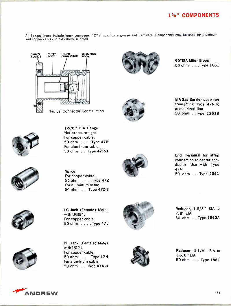
15/8" COMPONENTS
All flanged items include inner connector, "0" ring, silicone grease and hardware. Components may be used for aluminum and copper cables unless otherwise noted.
SWIVEL FLANGE
OUTER BODY
INNER CLAMPING CONDUCTOR BODY
Typical Connector Construction
1-5/8" EIA Flange Not pressure tight.
Tor copper cable. 50 ohm . . . .Type 47R For aluminum cable. 50 ohm . . Type 47R-3
Splice For copper cable. 50 ohm . . . .Type 47Z For aluminum cable. 50 ohm . . Type 47Z-3
LC Jack (Female) Mates with UG154. For copper cable. 50 ohm . . . . Type 47L
N Jack (Female) Mates with UG21. For copper cable. 50 ohm . . . Type 47N For aluminum cable. 50 ohm . . Type 47N-3
90°EIA Miter Elbow 50 ohm . . . Type 1061
EIA Gas Barrier use when connecting Type 47R to pressurized line 50 ohm . .Type 1261B
End Terminal for strap connection to center con- ductor. Use with Type 47R 50 ohm . . .Type 2061
Reducer, 1-5/8" EIA to 7/8" EIA 50 ohm . . Type 1860A
Reducer, 3.1/8" EIA to 1-5/8" EIA 50 ohm . . . Type 1861
ANDREW 61

1/4" AND 3/8" AIR DIELECTRIC HELIAX® CABLES
These small diameter HELIAX air dielectric coaxial cables are ideal to use as sampling lines and in low power or microwave frequency applications. For all uses, the inner and outer copper conductors assure optimum performance.
The connectors are compensated electrically and are easily attached with ordinary hand tools.
CABLE TYPES
Nominal Size 1/4" 3/8" Andrew Type H1-50 H2-50 Jacketed Andrew Type HJ1-50 HJ2-50
CHARACTERISTICS
Electrical Mechanical Nominal Size 1/4" 3/8" Nominal Size 1/4" 3/8" Impedance, ohms 50 50 Insulation Polyethylene Maximum Frequency, GHz* 21.6 14.2 Outer Conductor, O.D., inches .250 .375 Velocity, per cent 86.3 87 Diameter over jacket, inches .290 .435 Peak Power Rating, kw 3.1 6.5 Minimum Bending Radius, in. 2.5 3.75 Attenuation See page 88 Cable Weight Average Power Rating See page 89 Unjacketed, pounds per foot .06 .12
"For applications above 3 GHz, consult your Andrew Sales engineer. Jacketed, pounds per foot .07 .14
SHIPPING INFORMATION (Domestic)
Length, Feet
1/4" Cable 3/8" Cable Package Size, Inches Tare Weight Lbs.
0-300 0 to 250 Carton 31 x 31 x 2.5 5 301 to 600 251 to 500 Carton 48 x 48 x 6 15 601 to 3500 501 to 2000 Disposable reel 48 dia. x 24w 94
2001 to 3500 Disposable reel 72 dia. x 31w 315
COMPONENTS
N Jack (Female) Mates with UG21. 1/4" Cable .. Type 71N 3/8" Cable .. Type 72N
N Plug (Male) Mates with UG23. 1/4" Cable .. Type 71W 3/8" Cable .. Type 72W
End Terminal Adaptor (Type N Jack) Use with Type 71W or 72W con- nector on cable.
Type 13212-2
Splice, use pair of connectors 1/4" Cable Types 71N and 71W 3/8" Cable Types 72N and 72W
62

1/2" AIR DIELECTRIC HELIAX® CABLE
Type H4 HELIAX coaxial cable is widely used in sampling lines, low power and microwave frequency applications. The cable features copper inner and outer conductors.
The connectors are compensated electrically and are easily attached with ordinary hand tools.
CABLE TYPES
Andrew Type Military Number Jacketed Andrew Type
CHARACTERISTICS
H4-50 RG -268/U
HJ4-50
Electrical Impedance, ohms Maximum Frequency, GHz* Velocity, per cent Peak Power Rating, kw Attenuation Average Power Rating
50 10.9 91.4
10 See page 88 See page 89
"For applications above 3 GHz, consult your Andrew Sales engineer.
SHIPPING INFORMATION (Domestic)
Length, Feet Package Size, Inches
0 to 150 Carton 31 x 31 x 2.5 151 to 400 Carton 48 x 48 x 6 401 to 2000 Disposable reel 48 dia. x 24w 2001 to 2500 Disposable reel 72 dia. x 31w
COMPONENTS
Mechanical
Insulation Polyethylene Outer Conductor, O.D. inches .500 Diameter, over jacket, inches .580 Minimum Bending Radius, inches 5
Cable Weight Unjacketed, pounds per foot .21 Jacketed, pounds per foot .27
Tare Weight, Lbs.
5
15 94
315
N. Jack (Female) mates with UG21
Type 74N
UHF Jack (Female) mates with PL -259 . . .
Type 74U
Splice Type 74Z
N Plug (Male) mates with UG23 Type 74W
UHF Plug (Male) mates with SO -239A. Type 74P
End Terminal for strap connection tocentercon- ductor Type 74T
-10°/ANDREW 63

7/8" AIR DIELECTRIC HELIAX® CABLE
This HELIAX coaxial cable is preferred for low power R.F. systems. The low attenuation is also desirable for long runs in receiving antenna systems.
The cable is available with either copper or alumi- num corrugated outer conductor as shown in the ta-
ble below. The aluminum version (jacketed only) re-
tains most of the strength and flexibility of the copper cable while saving in weight and cost with a degradation of only 12% in attenuation and 10% in average power rating. The basic electrical and
mechanical data shown below apply to both copper and aluminum versions.
Low VSWR cable is available for radio relay systems operating in the 1.7 to 2.3 GHz band.
This cable is specially selected and tested version of 50 ohm copper, jacketed, cable. Maximum VSWR
over the band with Types 75AR or 75AG connectors is less than 1.08 with an RMS of less than 1.05.
CABLE TYPES
Outer Conductor Impedance, ohms Andrew Type Military Number
Jacketed Andrew Type
Military Number
Copper 50
H5-50 RG269A/U
HJ5-50 FSN 6145-939-9297
RG318/U
Low VSWR Andrew Type 25817
CHARACTERISTICS
Copper 75
H5-75 RG 284/ U
HJ5-75
Aluminum 50
LJ5-50 FSN 6145-814-8124
Electrical Mechanical
Impedance, ohms 50 75 Outer Conductor O.D., inches 1.005 Maximum Frequency, GHz* 5.2 5.6 Diameter, over jacket, inches 1.115 Velocity, percent 91.6 90.0 Minimum Bending Radius, inches 10
Peak Power Rating, kw 44 29 Cable Weight, pounds per foot Attenuation See pages 88 & 92 Unjacketed copper .43 Average Power Rating See pages 89 & 93 Jacketed copper .53
^ For applications above 3 GHz, consult your Andrew Sales engineer. Jacketed aluminum .38
SHIPPING INFORMATION (Domestic)
Length, Feet Package Size, Inches Tare Weight, Lbs.
to 50 Carton 48 x 48 x 6 15
51 to 200 Tire Wrap 48 dia. x 6w 15
201 to 550 Disposable reel 48 dia. x 24w 94 551 to 1500 Disposable reel 72 dia. x 31w 315 1501 to 2200 Returnable reel, Type 25190-3 74 dia. x 46w 925 2201 to 4500 Returnable reel, Type 25190-2 86 dia. x 52w 1645
The listing of military nomenclature and/or Federal Stock Numbers with Andrew part numbers is for reference only.
64
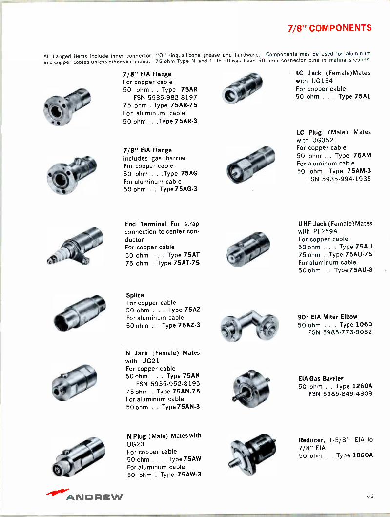
7/8" COMPONENTS
All flanged items include inner connector, "0" ring, silicone grease and hardware. Components may be used for aluminum
and copper cables unless otherwise noted. 75 ohm Type N and UHF fittings have 50 ohm connector pins in mating sections.
7/8" EIA Flange For copper cable 50 ohm . . Type 75AR
FSN 5935.982-8197 75 ohm . Type 75AR-75 For aluminum cable 50 ohm . .Type 75AR-3
7/8" EIA Flange includes gas barrier For copper cable 50 ohm . . .Type 75AG For aluminum cable 50 ohm . . Type75AG-3
End Terminal For strap connection to center con- ductor For copper cable 50 ohm . . . Type 75AT 75 ohm . Type 75AT-75
Splice For copper cable 50 ohm . . . Type 75AZ For aluminum cable 50 ohm . . Type 75AZ-3
N Jack (Female) Mates with UG21 For copper cable 50 ohm . . . Type 75AN
FSN 5935.952-8195 75 ohm . Type 75AN-75 For aluminum cable 50 ohm . . Type75AN-3
N Plug (Male) Mates with UG23 For copper cable 50 ohm . . . Type75AW For aluminum cable 50 ohm . Type 75AW-3
LC Jack (Female)Mates with UG154 For copper cable 50 ohm . . . Type 75AL
LC Plug (Male) Mates with UG352 For copper cable 50 ohm . . Type 75AM For aluminum cable 50 ohm . Type 75AM-3
FSN 5935-994-1935
UHF Jack (Female)Mates with PL259A For copper cable 50 ohm . . . Type 75AU 75 ohm . Type 75AU-75 For aluminum cable 50 ohm . . Type75AU-3
90° EIA Miter Elbow 50 ohm . . . Type 1060
FSN 5985-773-9032
EIA Gas Barrier 50 ohm . . Type 1260A
FSN 5985-849-4808
Reducer, 1-5/8" EIA to 7/8" EIA
50 ohm . . Type 1860A
ANDREW 65

15/8" AIR DIELECTRIC HELIAX® CABLE
This HELIAX coaxial cable is widely used for medium power HF, AM and FM antenna installations. The low attenuation also makes it popular at micro- wave frequencies.
The cable is available with either copper or alumi- num corrugated outer conductor as shown in the table below. Retaining most of the strength and flexibility of the copper cable, the aluminum version offers savings ¡n weight and cost with a degradation of only 12% in attenuation and 10% in average power rating. The basic electrical and mechanical data shown below apply to both copper and alumi- num versions.
Low VSWR cable is available for radio relay systems operating in the 1.7 to 2.3 GHz band. This cable is a specially selected and tested version of the 50 ohm copper, jacketed, cable. Maximum VSWR over the band with flanged connectors Types 87R, 87G, 87S or 87SG is less than 1.15 with an RMS of less than 1.08.
CABLE TYPES
Outer Conductor Copper Copper Aluminum Impedance, ohms 50 75 50 Jacketed Andrew Type HJ7-50A HJ7.75 LJ7-50A Federal Stock Number FSN 6145-822-4904 Military Number RG319A/U RG292/U RG378/ U
Low VSWR Andrew Type 25816A
CHARACTERISTICS
Electrical Mechanical
Impedance, ohms 50 75 Outer Conductor O.D., inches 1.830 Maximum Frequency, GHz 2.63 3.0 Diameter, over jacket, inches 2.000 Velocity, percent 92.1 92.4 Minimum Bending Radius, inches 20 Peak Power Rating, kw 145 98 Cable Weight, pounds per foot Attenuation See pages 88 & 92 Jacketed copper 1.04 Average Power Rating See pages 89 & 93 Jacketed aluminum .73
SHIPPING INFORMATION (Domestic)
Length, Feet Package Size, Inches Tare Weight, Lbs.
to 20 Box 9x9x252 120 21 to 100 Crate 72x72x24 120 101 to 200 Crate 108 x 108 x 30 180 201 to 400 Disposable reel 72 dia. x 31w 315 401 to 750 Returnable reel, Type 25190-3 74 dia. x 46w 925 751 to 1000 Returnable reel, Type 25190.2 86 dia. x 52w 1645 1001 to 3000 Returnable reel, Type 25190-5 98 dia. x 66w 2100
The listing of military nomenclature and/or Federal Stock Numbers with Andrew part numbers is for reference only.
66

15/8" COMPONENTS
All flanged items include inner connector, "0" ring, silicone grease and hardware. Components may be used for aluminum and copper cables unless otherwise noted.
1-5/8" EIA Flange For copper cable 50 ohm . . . .Type 87R 75 ohm . Type 77AR-75 For aluminum cable. 50 ohm . . Type 87R-3
FSN 5935-854-0855
1-5/8" EIA Flange in- cludes gas barrier For copper cable 50 ohm . . . .Type 87G For aluminum cable 50 ohm . . Type 87G-3
Reducer Connector to 7/8" EIA flange. For copper cable. 50 ohm . . . .Type 87S
Reducer Connector to 7/8" EIA flange includes gas barrier. For copper cable. 50 ohm . . . Type 87SG
Splice For copper cable 50 ohm . . . . Type 87Z 75 ohm . Type 77AZ-75 For aluminum cable 50 ohm . . Type 87Z-3
N Jack (Female) mates with UG21. For copper cable. 50 ohm . . . Type 87N For aluminum cable 50 ohm . . Type 87N-3
End Terminal for strap connection to center con- ductor. For copper cable. 50 ohm . . . . Type 87T 75 ohm . Type 77AT-75
LC Jack (Female) mates with UG154. For copper cable. 50 ohm . . . . Type 87L
90° EIA Miter Elbow 50 ohm . . . Type 1061
FSN 5985-867-1711 75 ohm . . . Type 1071
EIA Gas Barrier 50 ohm . . Type 1261B 75 ohm . . . Type 1271
EIA End Terminal 50 ohm . . . Type 2061
FSN 5935-010-7751 75 ohm . . . Type 2071
EIA Inner Connector 50 ohm . . Type 34660 75 ohm . . Type 24254
ANDAEW 67
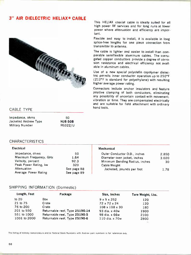
3" AIR DIELECTRIC HELIAX® CABLE
CABLE TYPE
Impedance, ohms Jacketed Andrew Type Military Number
CHARACTERISTICS
50 HJ8-50B RG322/U
This HELIAX coaxial cable is ideally suited for all high power RF services and for long runs at lower power where attenuation and efficiency are impor- tant.
Flexible and easy to install, it is available in long splice -free lengths for one piece connection from transmitter to antenna.
The cable is lighter and easier to install than com- parable semiflexible aluminum cables. The corru- gated copper conductors provide a degree of corro- sion resistance and electrical efficiency not avail- able in aluminum cables.
Use of a new special polyolefin copolymer dielec- tric permits inner conductor operation up to 250°F (212°F is standard for polyethylene) with resulting higher average power rating.
Connectors include anchor insulators and feature positive clamping of both conductors, eliminating any possibility of uncertain contact with movement, vibration or time. They are compensated electrically and are suitable for field attachment with ordinary hand tools.
Electrical Mechanical
Impedance, ohms 50 Outer Conductor O.D., inches 2.850 Maximum Frequency, GHz 1.64 Diameter over jacket, inches 3.020 Velocity, percent 92.3 Minimum Bending Radius, inches 30 Peak Power Rating, kw 320 Cable Weight Attenuation See page 88 Jacketed, pounds per foot 1.78 Average Power Rating See page 89
SHIPPING INFORMATION (Domestic)
Length, Feet Package Size, Inches Tare Weight, Lbs.
to 20 Box 9x9x252 120 21 to 75 Crate 72x72x24 120 76 to 200 Crate 108 x 108 x 30 180 201 to 550 Returnable reel, Type 25190-14 93 dia. x 40w 1900 551 to 1000 Returnable reel, Type 25190-5 98 dia. x 66w 2100 1001 to 2000 Returnable reel, Type 25190-6 110 dia. x 70w 2800
The listing of military nomenclature and/or Federal Stock Numbers with Andrew part numbers is for reference only.
68

3" COMPONENTS
All flanged items include inner connector, "0" ring, silicone grease and hardware.
3-1/8" EIA Flange (Male) 50 ohm . . Type 78ARM
3-1/8" EIA Flange (Female) 50 ohm . . Type 78ARF
3-1/8" EIA Flange (Male) includes gas barrier. 50 ohm . . Type 78AGM
3-1/8" EIA Flange (Fe- male) includes gas bar- rier. 50 ohm . . Type 78AGF
Reducer Connector to 1-5/8" EIA flange. 50 ohm . . . Type 78AS
Splice 50 ohm . . . Type 78AZ
LC Jack (Female) Mates with UG154 50 ohm . . . Type 78AL
3-1/8" EIA Flange Right angle (Male) 50 ohm . . Type 33875
Right Angle Splice (cable to cable) 50 ohm . . Type 33868.
90° EIA Miter Elbow 50 ohm . . Type 1062
EIA End Terminal 50 ohm . . . Type 2062
Reducer, 3-1/8" EIA to
1-5/8" EIA. 50 ohm . . . Type 1861
-1.1fr-ANDREW 69

5" AND 8" AIR DIELECTRIC HELIAX® CABLES
CABLE TYPES
Nominal Size 5" Jacketed Andrew Type HJ9-50
Military Number RG367/U
CHARACTERISTICS
8" HJ 10-50
These HELIAX coaxial cables are designed for very high power, low attenuation service. From VLF, LF and HF up through UHF -TV both sizes are being used to replace many 6-1/8" rigid transmission line installations.
The corrugated copper conductors and polyethylene jacket provide a combination of strength, flexibility, corrosion resistance and electrical efficiency not found in any other type of coaxial transmission line.
Installation of cable and connectors requires no special tools or bending fixtures.
Electrical Mechanical
Nominal Size 5', 8" Nominal Size 5" 8" Impedance, ohms 50 50 Outer Conductor OD, inches 5.00 8.00 Maximum Frequency, MHz 960 600 Diameter, over jacket, inches 5.20 8.20 Velocity, percent 93 94 Minimum Bending Radius, inches 50 63 Peak Power Rating, kw 830 1500 Cable Weight Attenuation See Page 88 Jacketed, pounds per foot 4.2 8.9 Average Power Rating See Page 89
SHIPPING INFORMATION (Domestic) Cable Size Length, Feet Returnable Reel Size, Inches Tare Weight, Lbs.
5" 151 to 600 Type 25190-9 128 dia. x 80w 3600 601 to 1100 Type 29076 146 dia. x 84w 4500
8" 151 to 400 Type 38269-2 154 dia. x 120w 6500 401 to 800 Type 38269-1 172 dia. x 120w 7000
COMPONENTS
All flanged items include inner connector, "0" ring, silicone
6 1/8" EIA Flange (Male) 5" cable . . . .Type 79R 8" cable . . . .Type 80R 6 1/8" EIA Flange (Male) includes gas barrier. 5" cable . . . .Type 79G 8" cable . . . .Type 80G
Splice 5" cable . . . .Type 79Z 8" cable . . . .Type 80Z
grease and hardware.
Reducer, 6-1/8" EIA to 3-1/8" EIA
Type 1872
90° EIA Miter Elbow . .
Type 1073
70
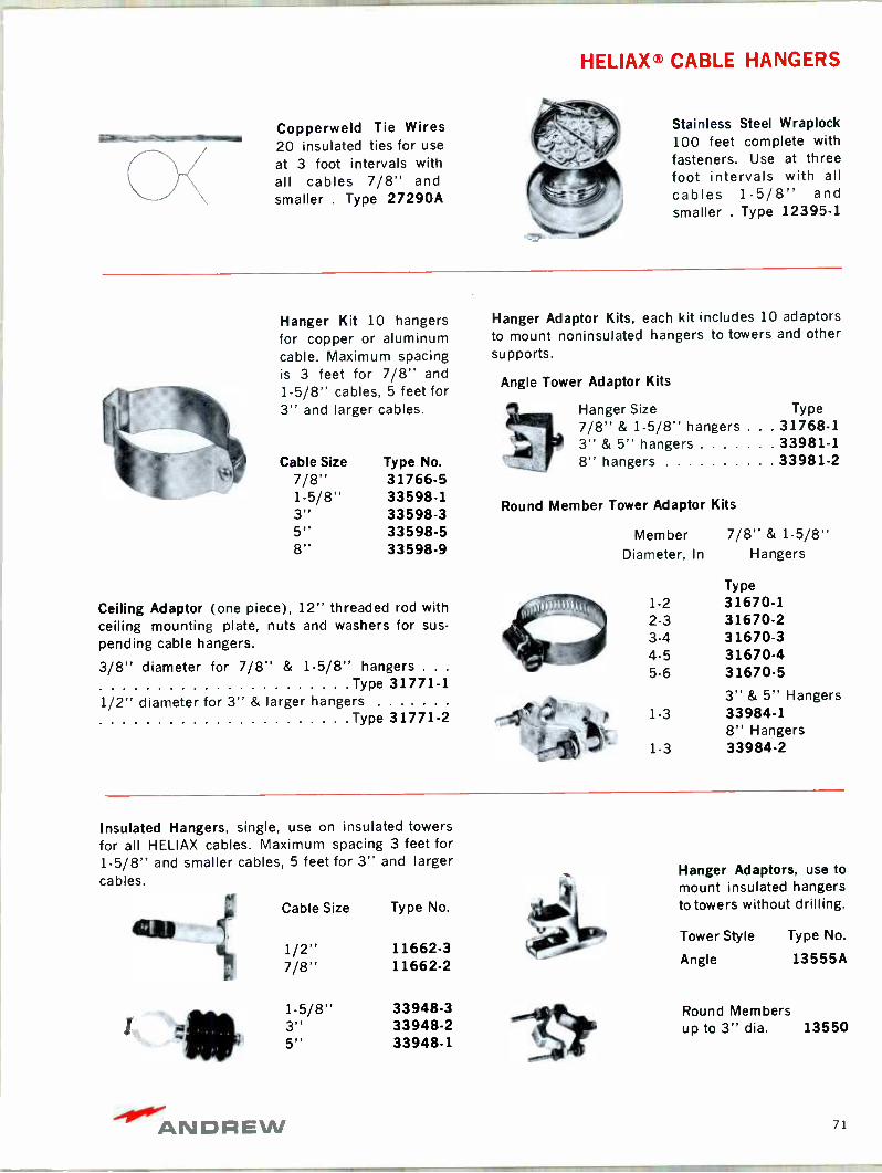
HELIAX® CABLE HANGERS
Copperweld Tie Wires 20 insulated ties for use
at 3 foot intervals with all cables 7/8" and smaller . Type 27290A
Stainless Steel Wraplock 100 feet complete with fasteners. Use at three foot intervals with all cables 1-5/8" and smaller . Type 12395-1
Hanger Kit 10 hangers for copper or aluminum cable. Maximum spacing is 3 feet for 7/8" and 1-5/8" cables, 5 feet for 3" and larger cables.
Cable Size Type No. 7/8" 31766-5 1-5/8" 33598-1 3" 33598-3 5" 33598-5 8" 33598-9
Ceiling Adaptor (one piece), 12" threaded rod with ceiling mounting plate, nuts and washers for sus- pending cable hangers.
3/8" diameter for 7/8" & 1-5/8" hangers . . .
Type 31771-1 1/2" diameter for 3" & larger hangers
Type 31771-2
Hanger Adaptor Kits, each kit includes 10 adaptors to mount noninsulated hangers to towers and other supports.
Angle Tower Adaptor Kits
Hanger Size Type 7/8" & 1.5/8" hangers . . 31768-1 3" & 5" hangers 33981-1 8" hangers 33981-2
Round Member Tower Adaptor Kits
Member 7/8" & 1-5/8" Diameter, In Hangers
Type 1-2 31670-1 2-3 31670-2 3-4 31670-3 4-5 31670-4 5-6 31670.5
3" & 5" Hangers 1-3 33984-1
8" Hangers 1-3 33984-2
Insulated Hangers, single, use on insulated towers for all HELIAX cables. Maximum spacing 3 feet for 1.5/8" and smaller cables, 5 feet for 3" and larger cables.
Cable Size Type No.
1/2" 11662-3 7/8" 11662-2
1-5/8" 33948-3 3" 33948-2 5" 33948-1
Hanger Adaptors, use to mount insulated hangers to towers without drilling.
Tower Style Type No.
Angle 13555A
Round Members up to 3" dia. 13550
ANDREW 71
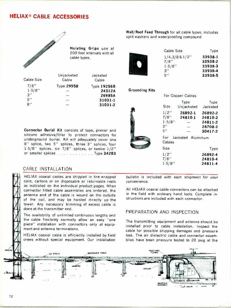
HELIAX® CABLE ACCESSORIES
Cable Size
7/8" 1-5/8" 3" 5" 8"
Hoisting Grips use at 200 foot intervals with all
Wall/Roof Feed Through for all cable types, includes split washers and waterproofing compound.
Cable Size Type
cable types. 1/4,3/8 & 1/2" 33938-1 7/8" 33938-2 1-5/8" 33938-3 3" 33938-4
Unjacketed Jacketed 5" 33938-5 Cable Cable
Type 29958 Type 19256B 24312A 26985A
31031-1 31031-2
Connector Burial Kit consists of tape, primer and silicone adhesive/filler to protect connectors for underground burial. Kit will adequately cover one 8" splice, two 5" splices, three 3" splices, four 1-5/8" splices, six 7/8" splices, or twelve 1/2" or smaller splices Type 34283
CABLE INSTALLATION
Grounding Kits
For Copper Cables
Type Size Unjacketed
1/2" 26892-1 7/8" 24810-1 1-5/8" 3" 5" -
Type Jacketed
26892-2 24810-2 24811-2 28708-2 30417-2
For Jacketed Aluminum Cables
Size Type
1/2" 26892-4 7/8" 24810-4 1-5/8" 24811-4
HELIAX coaxial caoles are shipped in tire wrapped coils, cartons or on disposable or returnable reels as indicated on the individual product pages. When connector fitted cable assemblies are ordered, the antenna end of the cable is wound on the outside of the coil, and may be hoisted directly up the tower. Any necessary trimming of excess cable is done at the transmitter end.
The availability of unlimited continuous lengths and the cable flexibility normally allow an easy "one piece" installation with connectors only at equip- ment and antenna terminations.
HELIAX coaxial cable is efficiently installed by field crews without special equipment. Our installation
GROUND
IGE SHIELD MESSENGER CABLE
bulletin is included with each shipment for your convenience.
All HELIAX coaxial cable connectors can be attached in the field with ordinary hand tools. Complete in- structions are included with each connector.
PREPARATION AND INSPECTION
The transmitting equipment and antenna should be installed prior to cable installation. Inspect the cable for possible shipping damages and pressure loss. The air dielectric cable and connector assem- blies have been pressure tested to 20 psig at the
FEED-THRU FLANGE \.\
GROUND
\.. AUTOMATIC DEHYDRATOR MANIFOLD ASSEMBLY
. .... -`." ..
i
72

HELIAX® CABLE INSTALLATION
factory and shipped at 10 psig. The factory pressure test is recorded on an inspection tag tied to the assembly.
Factory attached flange connectors are shipped with a blank cover to retain pres- sure during shipment. Do not remove the blank cover until the cable is installed as it affords protection to the connector face and prevents entry of foreign matter.
When unterminated cable is used, field at- tachment of the connector for the antenna end must be completed before hoisting. Re-
move the pressure cap prior to attaching the connector to the end of the cable in
accordance with the connector instructions. Keep all connector parts clean. Pressure test the assembly prior to hoisting.
Hoisting and Vertical Run A pulley and line are recommended for lift- ing HELIAX coaxial cables. Line size and lifting power requirements depend upon line length and cable size (see mechanical char- acteristics tables for cable weights). The hoist line should be long enough to allow tying to the cable along the vertical run during hoisting. Cable grips are used to sup- port the cable weight on the hoisting line and may be fastened to the tower as per- manent supports.
Position the reel at the tower base so that the cable pays off from the bottom of the reel. Support the reel on an axle to permit free rotation as the cable is being hoisted. Short lengths are uncoiled along the ground and away from the tower.
Place a protective covering over the con- nector to prevent damage during hoisting; then slowly hoist the cable. Rotation of the reel should be retarded to control payout of the cable.
MARKER BURIED JACKETED CARLE
Wraplock, copperweld tie wires or cable hangers are used to tie the cable perma- nently to vertical tower members-maxi- mum spacing of three feet for 1-5/8" and smaller cables, five feet for 3" and larger cables.
Horizontal Runs HELIAX coaxial cables may be supported on
cable ladders, buried, or suspended from a CGRBLI
PAE
messenger cable from the tower to the transmitter building. Jacketed HELIAX co- axial cables can be buried directly without fear of electrolytic action. A layer of sand surrounding the cable is usually adequate to protect the jacket from stones or other sharp objects. Above ground installations on messenger cables or other supports re- quire the same hangers and intervals as in
a vertical run, At the building entry, a drain / loop will prevent moisture from draining into the building. Exposed horizontal runs should be protected from falling ice and accumu- lation of snow by ice shields.
Bending of cable to the minimum bending radius (as shown in individual specifications) should be done with care.
Pressurization Air dielectric HELIAX coaxial cable should be maintained under dry air or dry nitrogen pressure at all times to prevent moisture condensation within the cable. Any positive pressure from 2 to 10 psig is adequate to prevent breathing during temperature cy- cles. An Andrew automatic dehydrator or manual dry air pump should be used to provide the recommended dry air pressure to assure long term, high efficiency opera- tion of your HELIAX coaxial cable installa- tion. For presurization equipment see pages 81 to 85.
..W` 17.5-'a! .,;d"./kwz.. dz.
"Zz--__=_=
-40."ANDAEW 73
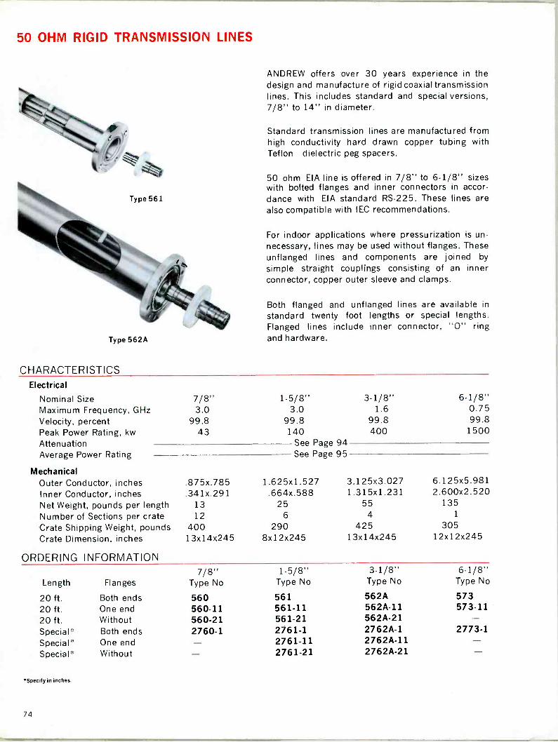
50 OHM RIGID TRANSMISSION LINES
Type 562A
CHARACTERISTICS
ANDREW offers over 30 years experience in the design and manufacture of rigid coaxial transmission lines. This includes standard and special versions, 7/8" to 14" in diameter.
Standard transmission lines are manufactured from high conductivity hard drawn copper tubing with Teflon dielectric peg spacers.
50 ohm EIA line is offered in 7/8" to 6-1/8" sizes with bolted flanges and inner connectors in accor- dance with EIA standard RS -225. These lines are also compatible with IEC recommendations.
For indoor applications where pressurization is un- necessary, lines may be used without flanges. These unflanged lines and components are joined by
simple straight couplings consisting of an inner connector, copper outer sleeve and clamps.
Both flanged and unflanged lines are available in
standard twenty foot lengths or special lengths. Flanged lines include inner connector, "0" ring and hardware.
Electrical
Nominal Size 7/8" Maximum Frequency, GHz 3.0 Velocity, percent 99.8 Peak Power Rating, kw 43 Attenuation Average Power Rating
Mechanical Outer Conductor, inches .875x.785 Inner Conductor, inches .341x.291 Net Weight, pounds per length Number of Sections per crate Crate Shipping Weight, pounds Crate Dimension, inches
1-5/8" 3-1/8" 6-1/8" 3.0 1.6 0.75
99.8 99.8 99.8 140 400 1500
See Page 94 See Page 95
1.625x1.527 3.125x3.027 6.125x5.981 .664x.588 1.315x1.231 2.600x2.520
13 25 55 135
12 6 4 1
400 290 425 305 13x14x245 8x12x245 13x14x245 12x12x245
ORDERING INFORMATION
Length Flanges 7/8"
Type No
1-5/8" Type No
3-1/8" Type No
6-1/8" Type No
20 ft. Both ends 560 561 562A 573 20 ft. One end 560-11 561-11 562A-11 573-11 20 ft. Without 560-21 561-21 562A-21 Special* Both ends 2760-1 2761-1 2762A-1 2773-1 Special* One end 2761-11 2762A-11 Special* Without 2761-21 2762A-21
'Specify in inches.
74

50 OHM RIGID LINE COMPONENTS
All flanged items are EIA standard and include inner connector, "0" ring, silicone grease and hardware except when noted.
90° Miter ElbowFlanged, brass construction
Line Size Type 7/8" 1060 1-5/8" 1061 3-1/8" 1062 6-1/8" 1073
Type N Adaptor (Female) Mates with UG21. Gas
tight with vent plug.
Line Size Type 7/8" 2260B 1-5/8" 2261A 3-1/8" 2262
90° Miter Elbow Unflanged, does not in- clude inner or outer con- nectors
Line Size Type 1-5/8" 1061-3 3-1/8" 1062-3
Type LC Adaptor (Fe- male) Mates with UG154 Gas tight with vent plug.
Line Size Type 7/8" 2360A 1-5/8" 2361A
45° Miter Elbow Flanged, brass construction
Line Size Type 3-1/8" 1162
Unpressurized Straight Coupling connects un - flanged lines and fittings. Includes inner connector and clamps.
Line Size Type 1-5/8" 4861A 3-1/8" 4862A
Gas Barrier, fixed male inner connectors on both ends. May be used as
gas inlet.
Line Size Type 7/8" 1260A 1-5/8" 1261B 3-1/8" 1262A 6-1/8" 1273
Soft Solder Field Flange Kit includes inner con- nector and hardware.
Line Size Type 7/8" 1560A 1-5/8" 1561A 3-1/8" 1562A 6-1/8" 1573A
Fixed Flange Kit consists of flange, silver solder Swivel Flange Kit consists of fixed flange, silver ring and flux. Inner conductor not included. solder ring and flux. Inner conductor not included.
Line Size Type Line Size Type 18096 18041 18200 18110
7/8" 18630 7/8" 1-5/8" 18631 1-5/8" 3-1/8" 15840 3-1/8" 6-1/8" 18111 6-1/8"
00°'ANDREW 75
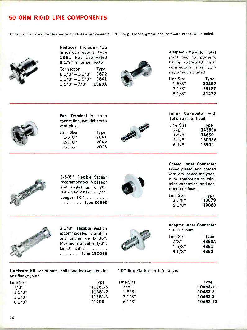
50 OHM RIGID LINE COMPONENTS
All flanged items are EIA standard and include inner connector, "0" ring, silicone grease and hardware except when noted.
Reducer Includes two inner connectors. Type 1861 has captivated 3-1/8" inner connector.
Connection Type 6-1/8"-3-1/8" 1872 3-1/8"-1-5/8" 1861 1-5/8"-7/8" 1860A
Adaptor (Male to male) joins two components having captivated inner connectors. Inner con- nector not included.
Line Size 1-5/8" 3-1/8" 6-1/8"
Type 30452 23187 31472
End Terminal for strap connection, gas tight with vent plug.
Line Size Type 1-5/8" 2061 3.1/8" 2062 6-1/8" 2073
1-5/8" Flexible Section accommodates vibration and angles up to 30°. Maximum offset is 1/4". Length 10".
Type 20695
3-1/8" Flexible Section accommodates vibration and angles up to 30°. Maximum offset is 1/2" Length 18"
Type 19209B
Inner Connector with Teflon anchor bead.
Line Size 7/8" 1-5/8" 3-1/8" 6-1/8"
Type 34389A 34660 15093A 18902
Coated Inner Connector silver plated and coated with dry baked molybde- num compound to mini- mize expansion and con- traction effects.
Line Size Type 3-1/8" 30079 6-1/8" 30080
Adaptor Inner Connector 50-51.5 ohm
Line Size 7/8" 1-5/8" 3-1/8"
Hardware Kit set of nuts, bolts and lockwashers for one flange joint.
"0" Ring Gasket for EIA flange.
Line Size Type Line Size 7/8" 11381-5 7/8" 1-5/8" 11381-2 1-5/8" 3-1/8" 11381-3 3-1/8" 6-1/8" 21206 6-1/8"
Type 4850A 4851 4852
Type 10683-11 10683-2 10683-3 10683-10
76

RIGID LINE COMPONENT DIMENSIONS
Component Description Line Size
Type No.
Dimensions, inches A B C
Weight, lbs. Net Shipping
7/8" 1-5/8" 3-1/8" 6-1/8"
1060 1061 1062 1073
3-5/64 2-7/16 2-1/4 2-57/64 2-7/16 3-1/2 4-3/16 4-3/16 5-3/16 5-5/8 5-5/8 8-1/8
1.4 1.8
3.6 4.0 8.5 9.5
23 27
90° Miter Elbow
13 }
C
1
A
45° Miter Elbow
3-1/8" 1162 4-1/2 4-1/2 5-3/16 9 10.5
B a A
.1
1-5/8" 3-1/8"
4861A 4862A
2-1/2 2-1/4 - 4-1/4 3-1/2 - 0.5 0.6
1.5 1.8
rre-vi uui!1!
U npressu rized
Straight
pg
1-5/8" 3-1/8" 6-1/8"
1860A 1861 1872
- 3-1/2 4-25/64 4-1/8 5-3/16 7/8 - 8-1/8 7-1/8
2.3 2.7 5.6 6.3
20 26 CSI Ems:
Reducer to 7/8 s Reducer to 1-5/8"
Reducer to 3-1/8"
A
7/8" 1-5/8" 3-1/8" 6-1/8"
1260A 1261B 1262A 1273
3-5/8 2-1/4 1-1/8 4-21/32 3-1/2 1-21/32 6-1/8 5-3/16 1-7/8 6-23/32 8-1/8 3-3/4
1.2 1.4 3.6 4.3 6.6 7.4
16.3 18
.. f
Gas Barrier ::=31 C-; g
A
Flexible Section
" 3" 20695 19209B
10 31/2 - 18 5 3/16 - 4.2 4.7
15 16.9 I liuo IIII1 I Ill
T
I=: i3
EIA Standard Flange Dimensions
Line Size, inches 7/8 1-5/8 3-1/8 6-1/8
Flange Overall Diameter, inches 2-1/4 3-1/2 5-3/16 8-1/8 Bolt Circle Diameter, inches 1.750 2.810 4.375 7.375 Number of Bolts 3 4 6 12 Bolt Size, inches 1/4 5/16 3/8 3/8
ANDREW 77
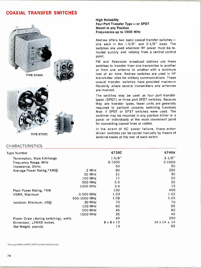
COAXIAL TRANSFER SWITCHES
TYPE 6730C
CHARACTERISTICS
High Reliability Four Port Transfer Type - or SPDT Mount in any Position Frequencies up to 1000 MHz
Andrew offers two basic coaxial transfer switches- one each in the 1-5/8" and 3-1/8" sizes. The switches are used wherever RF power must be re-
routed quickly and reliably from a central control point.
FM and Television broadcast stations use these switches to transfer from one transmitter to another or from one antenna to another with a minimum loss of air time. Andrew switches are used in HF
transmitter sites for military communications. These coaxial transfer switches have provided maximum flexibility where several transmitters and antennas are involved.
The switches may be used as four port transfer types (DPDT) or three port SPDT switches. Because they are transfer types, fewer units are generally required to perform complex switching functions than if SPDT or SP3T switches were used. The switches may be mounted in any position either in a
panel or individually at the most convenient point for connecting coaxial lines or cables.
In the event of AC power failure, these motor driven switches can be cycled manually by means of
external knobs at the rear of each switch.
Type Number 6730C 6740A
Termination, Male ElAflange 1.5/8" 3.1/8" Frequency Range, MHz 0.1000 0-1000 Impedance, Ohms 50 50 Average Power Rating,''` KW@ 2 MHz 80 350
30 MHz 21 90 100 MHz 11 50 500 MHz 5.0 20
1000 MHz 3.4 15
Peak Power Rating, 'KW 100 400 VSWR, Maximum 0-500 MHz 1.03 1.02
500-1000 MHz 1.08 1.05 Isolation, Minimum, dB@ 30 MHz 70 70
100 MHz 60 65 500 MHz 45 60
1000 MHz 35 45 Power Drain (during switching), watts 40 200 Dimension, LXWXD inches, 8 x 8 x 10 14 x 14 x 14
Net Weight, pounds 13 65
"At unity VSWR and 40 C (104F) ambient temperature.
78
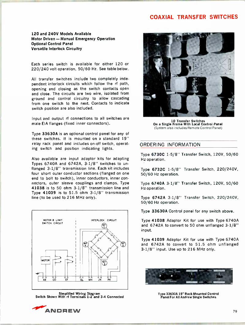
COAXIAL TRANSFER SWITCHES
120 and 240V Models Available Motor Driven - Manual Emergency Operation Optional Control Panel Versatile Interlock Circuitry
Each series switch is available for either 120 or 220/240 volt operation, 50/60 Hz. See table below.
All transfer switches include two completely inde- pendent interlock circuits which follow the rf path, opening and closing as the switch contacts open and close. The circuits are two wire, isolated from ground and control circuitry to allow cascading from one switch to the next. Contacts to indicate switch position are also included.
Input and output rf connections to all switches are male EIA flanges (fixed inner connectors).
Type 33630A is an optional control panel for any of these switches. It is mounted on a standard 19" relay rack panel and includes on -off switch, operat- ing switch and position indicating lights.
Also available are input adaptor kits for adapting Types 6740A and 6742A, 3-1/8" switches to un -
flanged 3-1/8" transmission line. Each kit includes four short outer conductor sections (flanged on one end to bolt to switch), inner conductors, inner con- nectors, outer sleeve couplings and clamps. Type 41038 is to 50 ohm 3-1/8" transmission line and Type 41039 is to 51.5 ohm 3-1/8" transmission line (to be used to 216 MHz only).
Simplified Wiring Diagram Switch Shown With rf Terminals 1-2 and 3-4 Connected
10 Transfer Switches On a Single Frame With Local Control Panel (System also includes Remote Control Panel)
ORDERING INFORMATION
Type 6730C 1-5/8" Transfer Switch, 120V, 50/60 Hz operation.
Type 6732C 1-5/8" Transfer Switch, 220/240V, 50/60 Hz operation.
Type 6740A 3-1/8" Transfer Switch, 120V, 50/60 Hz operation.
Type 6742A 3-1/8" Transfer Switch, 220/240V, 50/60 Hz operation.
Type 33630A Control panel for any switch above.
Type 41038 Adaptor Kit for use with Type 6740A and 6742A to convert to 50 ohm unflanged 3-1/8" input.
Type 41039 Adaptor Kit for use with Type 6740A and 6742A to convert to 51.5 ohm unflanged 3.1/8" input. Use up to 216 MHz only.
Type 33630A 19" Rack Mounted Control Panel For All Andrew Single Switches
-10."AIVDREW 79

COAXIAL SWITCHING EQUIPMENT
0111-DINS
Trans. 1 to Ant. 1
1-5/8" Switch Matrix
3 x 4 Switching Matrix
Connections Shown Trans. 2 to Load
e A
s e . ,4 :
' , .
Manual Patch Panel
Trans. 3 to Ant. 2
COAXIAL SWITCHING MATRICES
Andrew motor driven 1-5/8" and 3.1/8" coaxial transfer switches described on pages 78 and 79 can easily provide the basis for remotely controlled RF switching systems of any required degree of com- plexity. By arranging inputs and outputs in the form of a matrix, Andrew engineers have custom designed systems capable of performing a wide variety of RF switching functions.
For maximum ease of operation, provision is avail- able for direct visual routing indication on a remote control panel as well as on the matrix itself. RF
routing may be chosen in any desired sequence or path. Automatic interlocks are provided for deac- tivation of equipment during switching.
Complete versatile matrices permit connection of any combination of inputs to outputs and the chang- ing of circuits without interrupting other connec- tions. Nonversatile matrices require fewer switches but interrupt some existing paths when switching other input to output paths.
Contact your Andrew Sales Engineer for help with your switching matrix requirements.
, s.
.,
MANUAL PATCH PANELS
Andrew coaxial patch panels offer a less expensive solution to the switching problem than switching matrices, particularly where circuit changes are not made frequently or when switching speed is not
' .
critical.
Designs are available in 1-5/8" and 3-1/8" size lines from 1 by 2 combinations up to 16 by 17. Variations of existing designs can easily be made to suit any requirement.
Complete interlock systems are included to prevent switching while lines are energized.
80
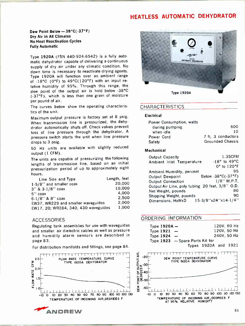
HEATLESS AUTOMATIC DEHYDRATOR
Dew Point Below -38°C( -37°F) Dry Air in All Climates No Heat Reactivation Cycles Fully Automatic
Type 1920A (FSN 440.924-6542) is a fully auto-
matic dehydrator capable of delivering a continuous supply of dry air under any climatic condition. No
down time is necessary to reactivate drying agents. Type 1920A will function over an ambient range
of -18°C (0°F) to 49°C(120°F) with an input re-
lative humidity of 95%. Through this range, the
dew point of the output air is held below -38°C (-37°F), which is less than one grain of moisture per pound of air.
The curves below show the operating characteris- tics of the unit.
Maximum output pressure is factory set at 8 psig.
When transmission line is pressurized, the dehy-
drator automatically shuts off. Check valves prevent loss of line pressure through the dehydrator. A
pressure switch starts the unit when line pressure drops to 3 psig.
50 Hz units are available with slightly reduced
output (1 CFM).
The units are capable of pressurizing the following
lengths of transmission line, based on an initial
pressurization period of up to approximately eight
hours. Line Size and Type Length, feet
1-5/8" and smaller coax 20,000 3" & 3-1/8" coax 10,000 5" coax 4,000 6.1/8" & 8" coax 2,500 EW37, WR229 and smaller waveguides 2,000 EW17, 20; WR284, 340, 430 waveguides 1,000
ACCESSORIES Regulating tank assemblies for use with waveguides
and smaller air dielectric cables as well as pressure and humidity alarm sensors are described in
page 83.
For distribution manifolds and fittings, see page 84.
2.5 f u. U
2.0 Lu
cc 1.5
ó L` 1.0
1111111IIIIIIIIIIIIlI111111 FLOW RATE TEMPERATURE CURVE
TYPE 1920A DEHYDRATOR -
Ili! II111I11111lIIllillllll -10 0 10 20 30 40 50 60 70 80 90 100 110 120
TEMPERATURE OF INCOMING AIR,DEGREES F
130
e 411r01141; iKtItAro11
CHARACTERISTICS
Electrical
Power Consumption, watts during pumping when idle
Power Cord Safety
Mechanical
Output Capacity Ambient Inlet Temperature
600 10
7 ft, 3 conductors Grounded Chassis
1.3SCFM -18° to 49°C
0° to 120°F Ambient Humidity, percent 95 Output Dewpoint Below -38°C( -37°F) Output Connection 1/8" M.P.T. Output Air Line, poly tubing 20 feet, 3/8" O.D. Net Weight, pounds 80 Shipping Weight, pounds 90 Dimensions, HxWxD 15-3/8"x24"x14-1/4"
ORDERING INFORMATION
Type 1920A - 120V, 60 Hz
Type 1921 - 120V, 50 Hz
Type 1924 - 240V, 50 Hz
Type 1923 - Spare Parts Kit for Types 1920A and 1921
á -20 z ? u_-30 0 u ou- w-40 I-
b ó-50 a 3 -60 0
11111IIIII11I1111111II11' DEW POINT TEMPERATURE CURVE
TYPE 1920A DEHYDRATOR
I1IIIliIIIIIlII111IIIill -10 0 10 20 30 40 50 60 70 80 90 100 110 120 130
TEMPERATURE OF INCOMING AIR, DEGREES F
AT 95% RELATIVE HUMIDITY
ANDREW 81
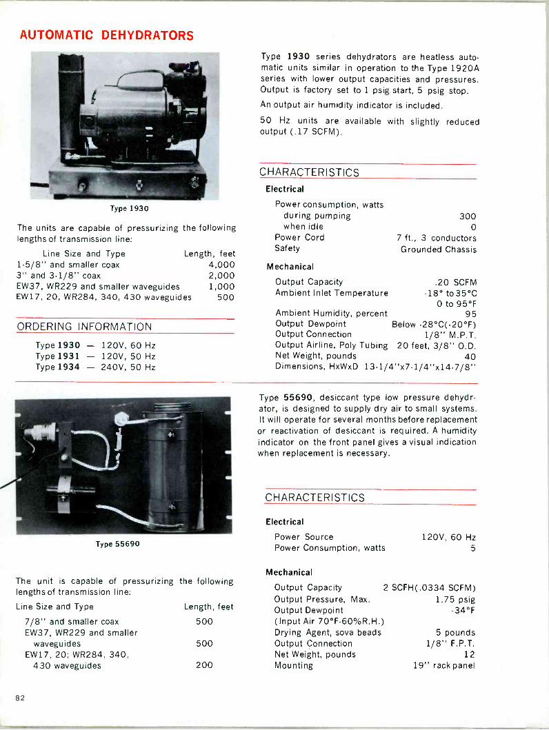
AUTOMATIC DEHYDRATORS
Type 1930
The units are capable of pressurizing the following lengths of transmission line:
Line Size and Type Length, feet 1-5/8" and smaller coax 4,000 3" and 3.1/8" coax 2,000 EW37, WR229 and smaller waveguides 1,000 EW17, 20, WR284, 340, 430 waveguides 500
ORDERING INFORMATION
Type 1930 - 120V, 60 Hz Type 1931 - 120V, 50 Hz Type 1934 - 240V, 50 Hz
Type 1930 series dehydrators are heatless auto- matic units similar in operation to the Type 1920A series with lower output capacities and pressures. Output is factory set to 1 psig start, 5 psig stop.
An output air humidity indicator is included.
50 Hz units are available with slightly reduced output (.17 SCFM).
CHARACTERISTICS
Electrical
Power consumption, watts during pumping when idle
Power Cord Safety
Mechanical
Output Capacity Ambient Inlet Temperature
300 0
7 ft., 3 conductors Grounded Chassis
.20 SCFM -18° to 35°C
0 to 95°F Ambient Humidity, percent 95 Output Dewpoint Below -28°C( -20°F) Output Connection 1/8" M.P.T. Output Airline, Poly Tubing 20 feet, 3/8" O.D. Net Weight, pounds 40 Dimensions, HxWxD 13-1/4"x7.1/4"x14.7/8"
Type 55690
The unit is capable of pressurizing lengths of transmission line:
Line Size and Type
7/8" and smaller coax EW37, WR229 and smaller
waveguides EW17, 20; WR284, 340,
430 waveguides
the following
Length, feet
500
500
200
Type 55690, desiccant type low pressure dehydr- ator, is designed to supply dry air to small systems. It will operate for several months before replacement or reactivation of desiccant is required. A humidity indicator on the front panel gives a visual indication when replacement is necessary.
CHARACTERISTICS
Electrical
Power Source Power Consumption, watts
Mechanical
Output Capacity Output Pressure, Max. Output Dewpoint (Input Air 70°F-60%R.H.)
120V, 60 Hz 5
2 SCFH(.0334 SCFM) 1.75 psig
-34°F
Drying Agent, soya beads 5 pounds Output Connection 1/8" F.P.T. Net Weight, pounds 12 Mounting 19" rack panel
82
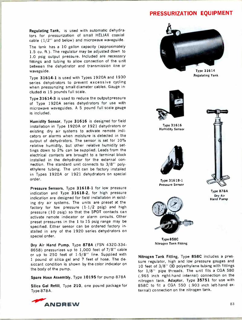
PRESSURIZATION EQUIPMENT
Regulating Tank, is used with automatic dehydra- tors for pressurization of small HELIAX coaxial
cable (1/2" and below) and microwave waveguide.
The tank has a 10 gallon capacity (approximately 1.5 cu. ft.). The regulator may be adjusted down to
1.0 psig output pressure. Included are necessary
fittings and tubing to allow connection of the unit between the dehydrator and transmission line or
waveguide.
Type 31614-1 is used with Types 1920A and 1930 series dehydrators to prevent excessive cycling when pressurizing small diameter cables. Gauge in-
cluded is 15 pounds full scale.
Type 31614-3 is used to reduce the output pressure of Type 1920A series dehydrators for use with
microwave waveguides. A 5 pound full scale gauge is included.
Humidity Sensor, Type 31616 is designed for field installation in Type 1920A or 1921 dehydrators or
existing dry air systems to activate remote indi- cators or alarms when moisture is detected in the output of dehydrators. The sensor is set for 10% relative humidity, but other relative humidity set-
tings down to 2% can be supplied. Leads from the electrical contacts are brought to a terminal block installed in the dehydrator for the external con- nection. The standard unit connects to 3/8" poly- ethylene tubing. The unit can be factory installed in Types 1920A or 1921 dehydrators on special order.
Pressure Sensors, Type 31618-1 for low pressure indication and Type 31618-2, for high pressure indication are designed for field installation in exist- ing dry air systems. The units are preset at the factory for low pressure (1-1/2 psig) and high pressure (10 psig) so that the SPDT contacts can
activate remote indicator or alarm circuits. Other preset pressures in the 1 to 15 psig range may be
specified. Either sensor can be ordered factory in-
stalled in any of the 1920 series dehydrators on
special order.
Dry Air Hand Pump, Type 878A (FSN 4320-334- 8658) pressurizes up to 1,000 feet of 7/8" cable or up to 250 feet of 1.5/8" line. Supplied with 1 pound of silica gel and 7 feet of hose. The de- siccant condition is shown by the color indicator on
the body of the pump.
Spare Hose Assembly, Type 10195 for pump 878A
Silica Gel Refill, Type 210, one pound package for Type 878A.
Type 31614 Regulating Tank
Type 31616 Humidity Sensor
Type 31618.1 Pressure Sensor
Type 878A Dry Air
Hand Pump
Type 858C Nitrogen Tank Fitting
Nitrogen Tank Fitting, Type 858C includes a pres- sure regulator, high and low pressure gauges and
10 feet of 3/8" OD polyethylene tubing with fittings for 1/8" pipe threads. The unit fits a CGA 580 (.965 inch right-hand internal) connection on the nitrogen tank. Adaptor, Type 35751 for use with
858C to fit a CGA 550 (.903 inch left-hand ex-
ternal) connection on the nitrogen tank.
ANDREW 83

PRESSURIZATION EQUIPMENT
Gas Distribution Manifold, Type 6600A (FSN 5820- 392-7233) includes pressure gauges, needle valves, fittings and 15 feet of 3/8" polyethylene tubing for each outlet. Specify number of outlets required.
Type 6600A
Gas Inlet Valve has 1/8" male pipe thread . . .
Type 3017
Pressure Gauge reads 0- 30 psi and has 1/8" male pipe thread. Indoor use only . . . Type 3500
Release Valve has 1/8" male pipe thread on one end Type 3027
Release Valve has 1/8" male pipe thread on both ends Type 4944
Release Valve has 1/8" pipe threads, male one end, female other end.
Type 4949
Pipe Tee 1/8" female pipe thread each outlet . . Type 3028
Street Tee One male and 2 female 1/8" pipe thread outlets .
Type 3022
Pipe Nipple 1/8" male pipe threads entire length . .Type 3026
Male Connector for 3/8" poly tubing, has 1/8" male pipe threads one end . . . .Type 31680-1
Male Connector for 3/8" poly tubing, has 1/4" male pipe threads one end . . . Type 31680-2
Male Branch Tee for 3/8" poly tubing, has 1/4" male pipe threads on one outlet. .
Type 31680-3
Elbow for 3/8" poly tubing, has 1/8" male pipe threads one end . .
Type 31680-4
Polyethylene Tubing 3/8" diameter . . Type 25435
Mounting Strap For 3/8" poly tubing Type 10712-24
Pipe Plug Has 1/8" male pipe thread Type 3018
Thread Lubricant 4 cc tube Type 3012
84
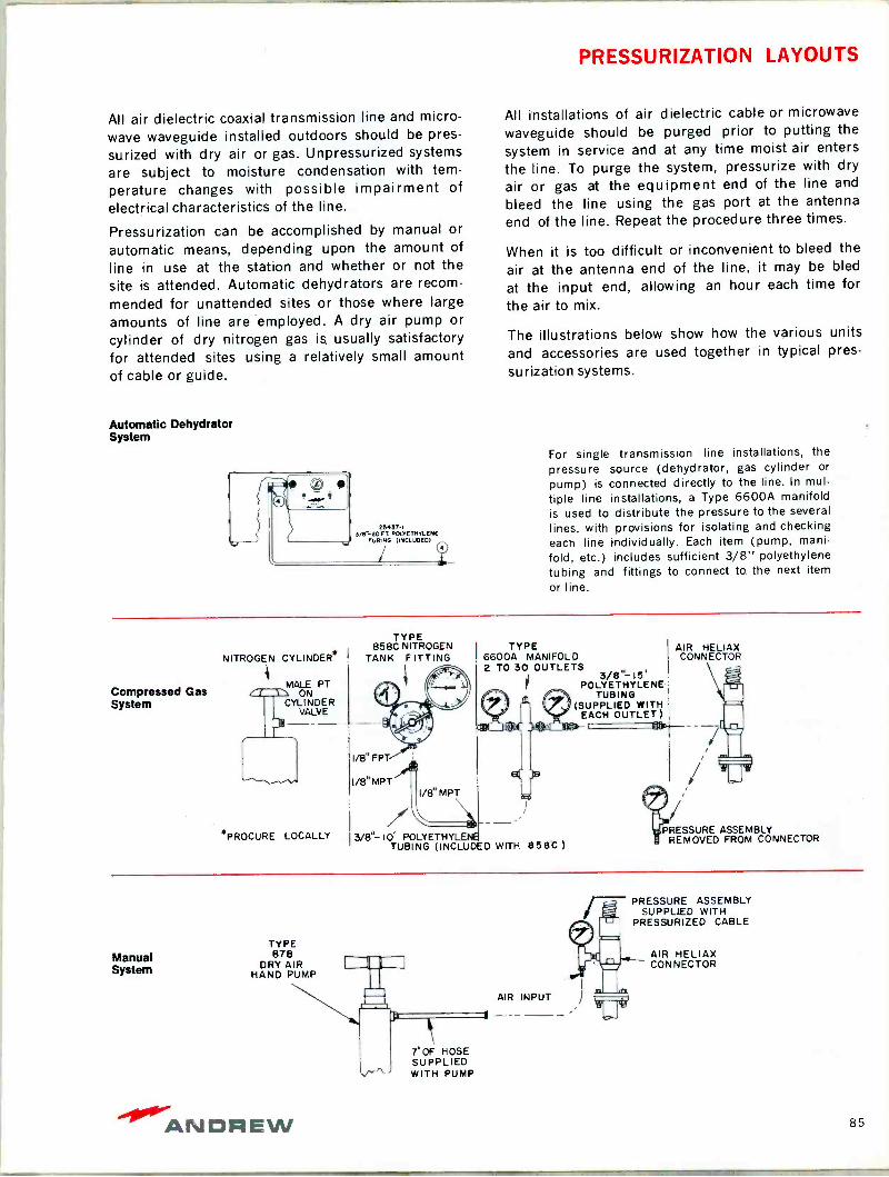
PRESSURIZATION LAYOUTS
All air dielectric coaxial transmission line and micro-
wave waveguide installed outdoors should be pres-
surized with dry air or gas. Unpressurized systems
are subject to moisture condensation with tem-
perature changes with possible impairment of
electrical characteristics of the line.
Pressurization can be accomplished by manual or
automatic means, depending upon the amount of
line in use at the station and whether or not the
site is attended. Automatic dehydrators are recom-
mended for unattended sites or those where large amounts of line are employed. A dry air pump or cylinder of dry nitrogen gas is usually satisfactory for attended sites using a relatively small amount of cable or guide.
Automatic Dehydrator System
25.37-I 3/13'-20 Ç. POLYETHYLENE
TUBING (INCLUDED)
All installations of air dielectric cable or microwave
waveguide should be purged prior to putting the
system in service and at any time moist air enters
the line. To purge the system, pressurize with dry
air or gas at the equipment end of the line and
bleed the line using the gas port at the antenna
end of the line. Repeat the procedure three times.
When it is too difficult or inconvenient to bleed the
air at the antenna end of the line, it may be bled
at the input end, allowing an hour each time for the air to mix.
The illustrations below show how the various units
and accessories are used together in typical pres-
surization systems.
For single transmission line installations, the pressure source (dehydrator, gas cylinder or
pump) is connected directly to the line. In mul-
tiple line installations, a Type 6600A manifold is used to distribute the pressure to the several
lines, with provisions for isolating and checking each line individually. Each item (pump, mani-
fold, etc.) includes sufficient 3/8" polyethylene tubing and fittings to connect to the next item
or line.
Compressed Gas System
NITROGEN CYLINDER.
MALE PT ON
CYLINDER VALVE
*PROCURE LOCALLY
TYPE 858C NITROGEN
TANK FITTING
I/8" FPT
1/8" MPT 1/8" MPT
TYPE 6600A MANIFOLD 2 TO 30 OUTLETS
3/8"- IOC POLYETHYLENE TUBING (INCLUDED WITH 858C )
AIR HELIAX CONNECTOR
3/8"-15' POLYETHYLENE
TUBING (SUPPLIED WITH
EACH OUTLET)
PRESSURE ASSEMBLY REMOVED FROM CONNECTOR
Manual System
TYPE 878
DRY AIR HAND PUMP
7' OF HOSE SUPPLIED WITH PUMP
AIR INPUT
r- PRESSURE ASSEMBLY SUPPLIED WITH
PRESSURIZED CABLE
AIR HELIAX CONNECTOR
-000."ANDAEW 85
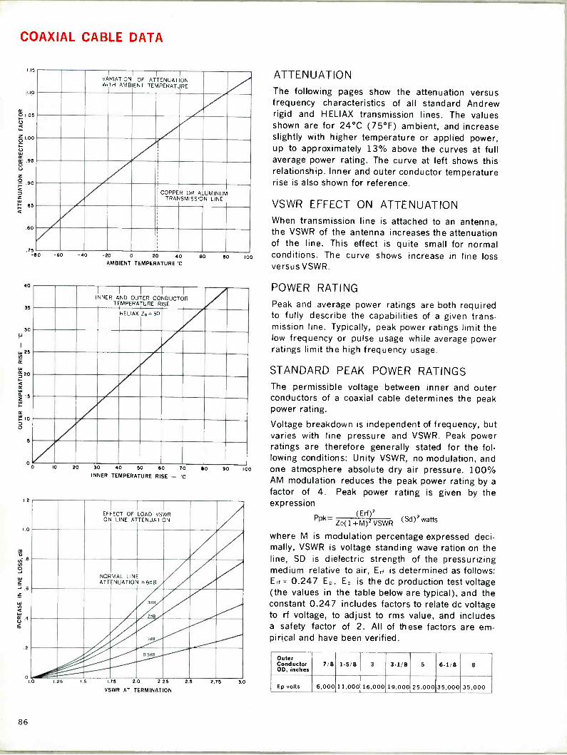
COAXIAL CABLE DATA
1.15
1.10
O 1.05
U Li -
CO ó .95
O . 17: 90
.B5 ¢
.80
.75
40
35
30 U
W 25 N_
; 20 I_
f 15 W H
lo
ó
e
VARIATION WITH
I
AMBIENT OF ATTENUATION
TEMPERATURE
I
i
1
I
-I
COPPER I TRANSMISSION
-I
OR ALUMINUM LINE
-80 -60 -40 -20 0 20 40 AMBIENT TEMPERATURE *C
60 80 loo
I I I I
INNER AND OUTER CONDUCTOR TEMPERATURE RISE
HELIAX Z°=50
,00
1.2
0
10 20 30 40 50 60 70
INNER TEMPERATURE RISE - °C
80 90 100
o lo
EFFECT OF LOAD VSWR ON LINE ATTENUATION
NORMAL LINE ATTENUATION =6dB
1dB
0.5dß
1.25 15 175 2 0 2.25
VSWR AT TERMINATION
25 2.75 3.0
ATTENUATION
The following pages show the attenuation versus frequency characteristics of all standard Andrew rigid and HELIAX transmission lines. The values shown are for 24°C (75°F) ambient, and increase slightly with higher temperature or applied power, up to approximately 13% above the curves at full average power rating. The curve at left shows this relationship. Inner and outer conductor temperature rise is also shown for reference.
VSWR EFFECT ON ATTENUATION When transmission line is attached to an antenna, the VSWR of the antenna increases the attenuation of the line. This effect is quite small for normal conditions. The curve shows increase in line loss versus VSWR.
POWER RATING
Peak and average power ratings are both required to fully describe the capabilities of a given trans- mission line. Typically, peak power ratings limit the low frequency or pulse usage while average power ratings limit the high frequency usage.
STANDARD PEAK POWER RATINGS The permissible voltage between inner and outer conductors of a coaxial cable determines the peak power rating.
Voltage breakdown is independent of frequency, but varies with line pressure and VSWR. Peak power ratings are therefore generally stated for the fol- lowing conditions: Unity VSWR, no modulation, and one atmosphere absolute dry air pressure. 100% AM modulation reduces the peak power rating by a
factor of 4. Peak power rating is given by the expression
Ppk= (Erf
(9:92 wattsZo(14- VSWR
where M is modulation percentage expressed deci- mally, VSWR is voltage standing wave ration on the line, SD is dielectric strength of the pressurizing medium relative to air, Eri is determined as follows: Eri = 0.247 E. Ep is the dc production test voltage (the values in the table below are typical), and the constant 0.247 includes factors to relate dc voltage to rf voltage, to adjust to rms value, and includes a safety factor of 2. All of these factors are em- pirical and have been verified.
Outer Conductor OD, inches
7/8 1-5/8 3 3-1/8 5 6-1/8 8
Ep volts 6,000 11,000 16,000 19,000 25,000 35,000 35,000
86
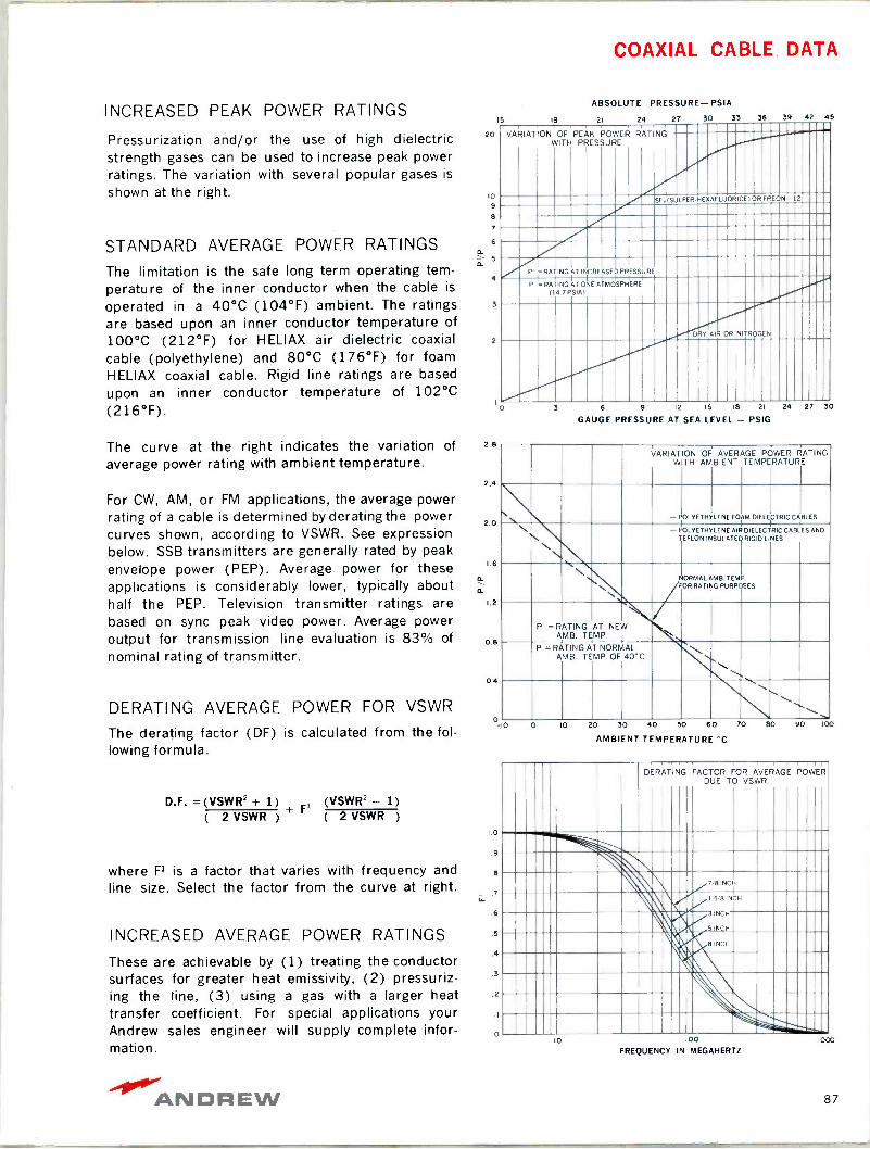
COAXIAL CABLE DATA
INCREASED PEAK POWER RATINGS
Pressurization and/or the use of high dielectric strength gases can be used to increase peak power ratings. The variation with several popular gases is
shown at the right.
STANDARD AVERAGE POWER RATINGS
ABSOLUTE PRESSURE-PSIA
15 18 21 24 27 30 33 36 39 42 45
20
10
9
8
7
6 5.
5 o.
The limitation is the safe long term operating tern - 4
perature of the inner conductor when the cable is
operated in a 40°C (104°F) ambient. The ratings 3
are based upon an inner conductor temperature of 100°C (212°F) for HELIAX air dielectric coaxial 2
cable (polyethylene) and 80°C (176°F) for foam HELIAX coaxial cable. Rigid line ratings are based upon an inner conductor temperature of 102°C (216°F).
The curve at the right indicates the variation of
average power rating with ambient temperature.
For CW, AM, or FM applications, the average power rating of a cable is determined by derating the power curves shown, according to VSWR. See expression below. SSB transmitters are generally rated by peak envelope power (PEP). Average power for these applications is considerably lower, typically about half the PEP. Television transmitter ratings are based on sync peak video power. Average power output for transmission line evaluation is 83% of
nominal rating of transmitter.
DERATING AVERAGE POWER FOR VSWR
The derating factor (DF) is calculated from the fol- lowing formula.
D.F. =(VSWR2 + 1) 1 (VSWR2 - 1) ( 2 VSWR )
+ F ( 2 VSWR )
where Fl is a factor that varies with frequency and line size. Select the factor from the curve at right.
2.8
2.4
2.0
1.6
a. a
1.2
0.8
0.4
o
AMBIENT TEMPERATURE °C
1.0
.9
INCREASED AVERAGE POWER RATINGS
These are achievable by (1) treating the conductor surfaces for greater heat emissivity, (2) pressuriz- ing the line, (3) using a gas with a larger heat .2
transfer coefficient. For special applications your Andrew sales engineer will supply complete infor- mation.
VARIATION OF PEAK POWER RATING WITH PRESSURE
SF (SULF ER -HEX AFLUOR IDEI OR FREON -12
P - RATING AT INCREASED PRESSURE
P = RATING AT ONE ATMOSPHERE (14.7 PSIA1
D ºY Al R OR NIT R DG EN
3 6 9 12 15 18 21 24 27 30
GAUGE PRESSURE AT SEA LEVEL - PSIG
VARIATION WITH
OF AMBIENT
AVERAGE POWER TEMPERATURE
RATING
- POLYETHYLENE FOAM DIELECTRIC CABLES
N N
N N
-- POLYETHYLENE TEFLON
AIR INSULATED
DIELECTRIC RIGID LINES
CABLES AND
\ \ \ NORMAL
/FOR AMB.
RATING TEM
PURPOSES .
P' =RATING AMB. TEMP.
AT NEW
P =RATING AMB.
AT TEMP.
NORMAL OF 40'C \
\ 80 90 100
DERATING FACTOR FOR AVERAGE POWER DUE TO VSWR
7/8 INC
1-5/8 INCH
3 INCH
5 INCH
8 INCH
10 100
FREQUENCY IN MEGAHERTZ
1000
ANDREW 87
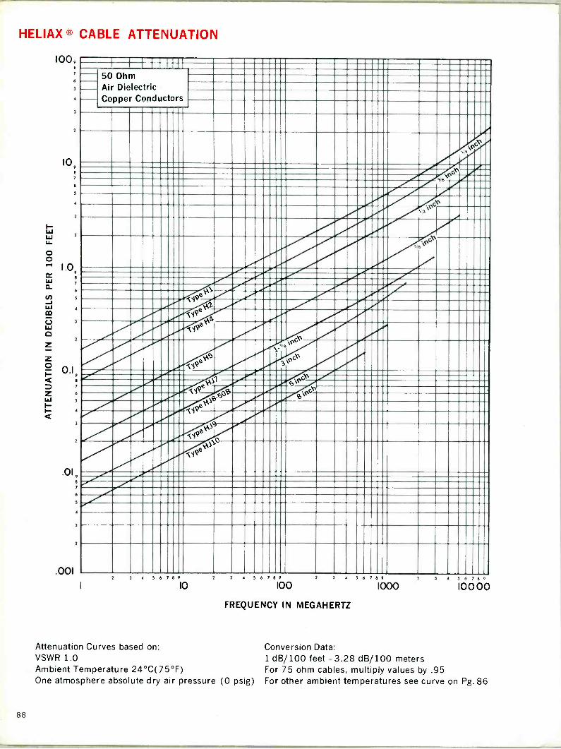
HELIAX ® CABLE ATTENUATION
1009
6
3
1
10, e 7
6
5
3
z
1.0, 8
6
5
3
3
0.19 e 7
s
l
3
3
.01, 8
7
6
5
3
7
.001
50 Ohm Air Dielectric Copper Conductors
r
ß4r .44
3 3 56 89
10 4 5 6 7 8 9
100 3 4 5 6 7 8 9 2
FREQUENCY IN MEGAHERTZ
1000 3 5 6 7 8
10000
Attenuation Curves based on: Conversion Data: VSWR 1.0 1 dB/100 feet =3.28 dB/100 meters Ambient Temperature 24°C(75°F) For 75 ohm cables, multiply values by .95 One atmosphere absolute dry air pressure (0 psig) For other ambient temperatures see curve on Pg. 86
88
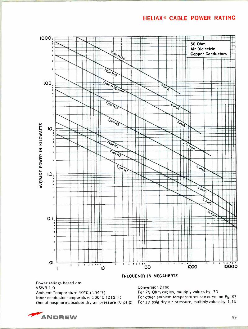
HELIAX® CABLE POWER RATING
10009 8
7
6
5
1
2
100,
1
10é
5
1
2
1.0, 8
1
2
. `
Ty
Io
ype
kilb 1
_ Oe- I i '..uIi-
11. 11111 3hch- I _ 01 . ' TyAe `1 R'_ I' ̀ _ _
wen h îÌÌIIi!tiIii
-I;' 1111 . ',Ch
Irt. 111111--liii.
h
., `% ----1 Ci------ ch .... 0.1,
.01
If I f H 50 Ohm Air Dielectric Copper Conductors
1
i 4 5 6 7 8 9
10 2 3 4 5 6 7 8 9
100 2 3 4 5 6 7 8 9
FREQUENCY IN MEGAHERTZ
Power ratings based on: VSWR 1.0 Ambient Temperature 40°C (104°F) Inner conductor temperature 100°C (212°F) One atmosphere absolute dry air pressure (0 psig)
1000 2 3 4 5 6 7 8 9
10000
Conversion Data: For 75 Ohm cables, multiply values by .70 For other ambient temperatures see curve on Pg.87 For 10 psig dry air pressure, multiplyvalues by 1.15
ANDREW 89
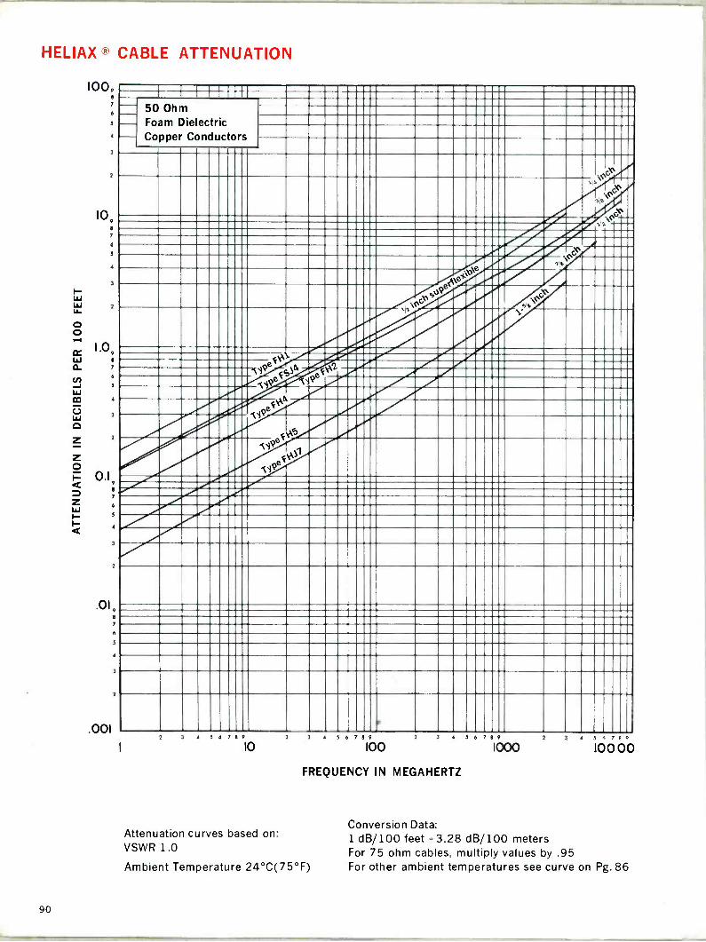
HELIAX ® CABLE ATTENUATION
1009 7
6
5
4
3
109
6
5
.
3
2
1.09 e
5
l
3
2
0.1 9
7
6
5
3
2
.019
7
.001
l 3
2
1 I 11 I
50 Ohm Foam Dielectric Copper Conductors
Nl ,ypeeg)A j!e-
'«`)
.d111111131111I
2 3 4 S 6 8 9
10
Attenuation curves based on: VSWR 1.0
4 5 6 7 8 9
100 3 4 5 6 7 8 9 2
FREQUENCY IN MEGAHERTZ
Ambient Temperature 24°C(75°F)
1000 3 5 4 7 8 0
10000
Conversion Data: 1 dB/100 feet =3.28 dB/100 meters For 75 ohm cables, multiply values by .95 For other ambient temperatures see curve on Pg. 86
90

HELIAX® CABLE POWER RATING
10009 8
7
6
2
100,
10, e
7
6
5
2
1.0, 8
7
6
,
3
2
0.1,
.01
5
50 Ohm Foam Dielectric Copper Conductors
pli
1
3 4 5 6 8 9
10 2 3 4 6 89
100 2 3 4 5 6 7 8 9 2
FREQUENCY IN MEGAHERTZ
Power Ratings based on: VSWR 1.0 Ambient temperature 40°C (104°F) Inner conductor temperature 80°C (176°F)
1000 3 4 5 7 8 9
10000
Conversion Data: For 75 ohm cables, multiply values by .70 For other ambient temperatures see curve on Pg. 87
-40°'ANDREW 91

HELIAX ® CABLE ATTENUATION
looº 7
5
]
2
109
7
5
l
2
1.09 8
7
6
]
2
0.19 8
7
6
5
.019
6
l
2
001
I l i-1-+
50 Ohm Air and Foam Dielectric Aluminum Outer Conductor
to
5 6 7 8 9
Io
5 6 8 9
100 2 3 4 5 6 8 9 2
FREQUENCY IN MEGAHERTZ
Attenuation curves based on: VSWR 1.0 Ambient Temperature 24°C (75°F) One atmosphere absolute dry air pressure (0 psig) (air cables)
1000 3 5 6 7 8 9
10000
Conversion Data: 1 dB/100 feet = 3.28 dB/100 meters For 75 ohm cables, multiply values by .95 For other ambient temperatures see curve on Pg.86
92
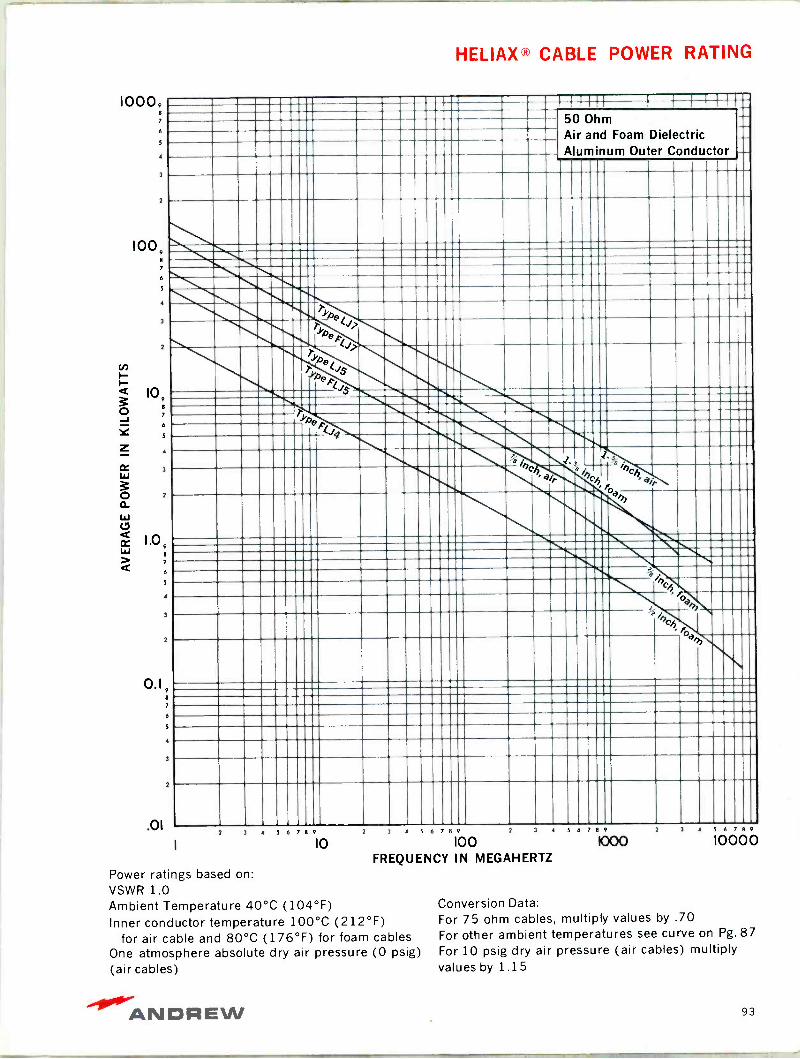
HELIAX® CABLE POWER RATING
10009 a
7
100,
s
3
2
10,
5
a
2
1.0,
6
2
0.1,
.01
---... ....---- - -.--.....-.. C .i 50 Ohm I Air and Foam Dielectric Aluminum Outer Conductor
1 1111 !iIIIIII
U
tlli!lilllll!!111lI S-,-, !ëTIT
yyp
J!!iJiIIIIIII_11111111 111 ---------... mama
mammonism4 \m' -mamma mamma U111IIÌÌ\ 1. 31 ?"1111113111111111
1111101 lIliWIn`h °°h'r 111111 wil- _; ̀ \ f°d 1 .. li,._ 1111111111111111 IiI!!iIIg\n11111 111ZIM331 ZIMI\ a;. !1!_ 11111
15II II\ 'h II 111_11!! ` 1'11 11111111111 1111111111
2 3 4 5 6 7 8 9 2 3 4 5 6 8 9 2 3 4 5 6 7 8 9
10 100 FREQUENCY IN MEGAHERTZ
4 5 6 8 9
10000
Power ratings based on: VSWR 1.0 Ambient Temperature 40°C (104°F) Conversion Data:
Inner conductor temperature 100°C (212°F) For 75 ohm cables, multiply values by .70
for air cable and 80°C (176°F) for foam cables For other ambient temperatures see curve on Pg. 87
One atmosphere absolute dry air pressure (0 psig) For 10 psig dry air pressure (air cables) multiply
(air cables) values by 1.15
ANDREW 93
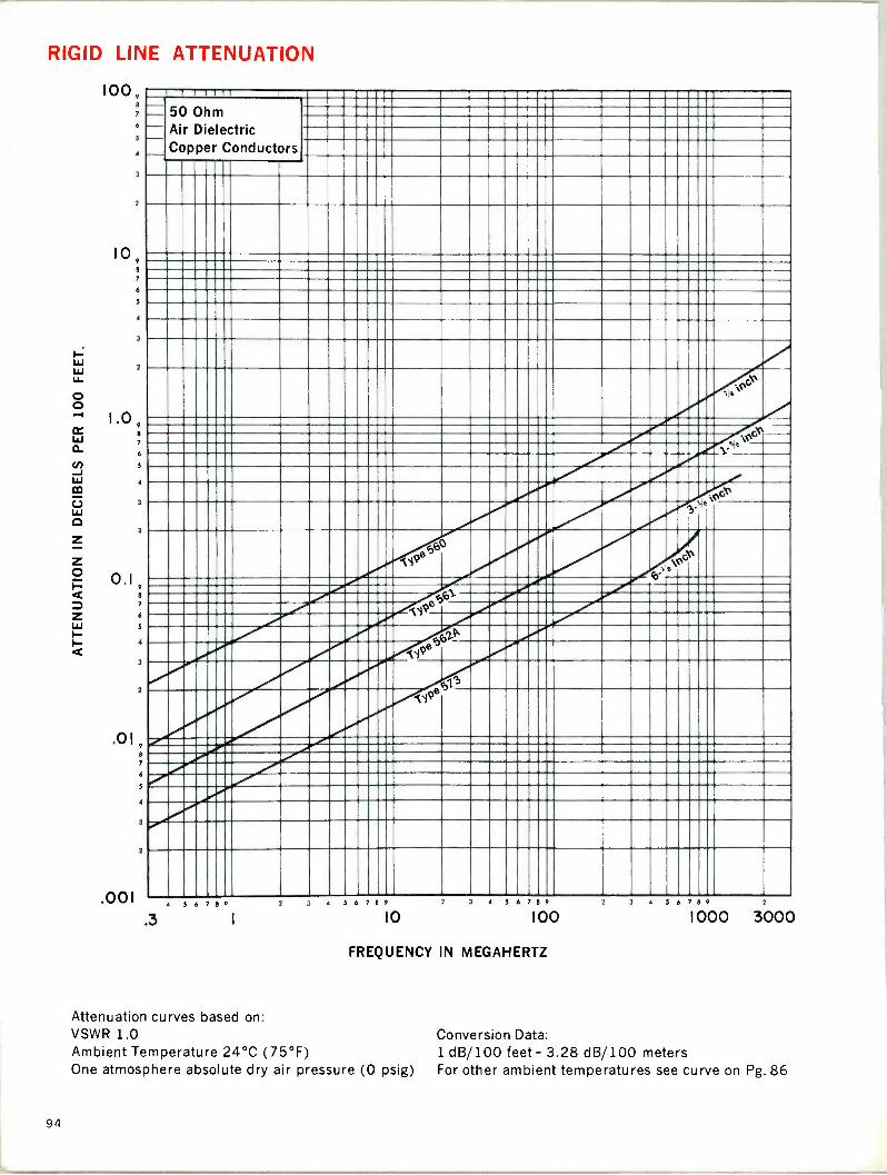
RIGID LINE ATTENUATION
100 9
8
7
6
5
2
2
109 8
7
6
5
1.09 8
7
6
5
0.1 8
7
6
5
2
.019 8
7
6
5
J
2
.001 4 5 6 7 8 9
.3
I I TT TT T 1
50 Ohm Air Dielectric Copper Conductors
C:(%
, ¡ 0O`
xoe
.r
1 5 6 8 9
10 1 3 4 6 7 8 9 2 3 4 6 7 8 9 2
I00 1000 3000
FREQUENCY IN MEGAHERTZ
Attenuation curves based on: VSWR 1.0 Ambient Temperature 24°C (75°F) One atmosphere absolute dry air pressure (0 psig)
Conversion Data: 1 dB/ 100 feet = 3.28 dB/ 100 meters For other ambient temperatures see curve on Pg. 86
94

RIGID LINE POWER RATING
10000,
6
5
4
1000, 7
6
5
100
10
LO
e
7
6
5
4
7
6
5
«BMW» 1_33 M
11 I",-1 1 =1 i111 lii'ili 1 i' I111Illli11 1i111 1111lo118 ammo I iuiiiiiiiiii__11111111 ii 11ii111
11:i..1':D:CC:1:=Cl 11:::11 n111ani -111u11 '\ 111Nll MI MIMI ; 111 ,1 ..11lI..1111..111 11111 , IIIIiiiIIIIIÌ'UIIIIIiÌU!IIIIIII_I . MILIL-m:E13131
\i11 1 . \.. B%, :1:1 ̀' .
11 IilI r'l1111111 611MB lil 1 IIII111 pess 1111i1111 11111111 Willa --- 6
VOW `!11! !
011-11I190M\ 111111 1111111 1ZI111111III 1111111 11111111
11 1
-M wow11111111 anI- --- 11 1
inz
I
50 Ohm Air Dielectric Copper Conductors
.01
.3 5 6 7 8 9
Power ratings based on: VSWR 1.0 Ambient Temperature 40°C (104°F) Conversion Data:
Inner conductor temperature 102°C (216°F) For other ambient temperatures see curve on Pg.87 One atmosphere absolute dry air pressure (0 psig) For 10 psig dry air pressure, multiplyvaluesby 1.15
1
2 3 4 5 6 7 8 9
IO
3 4 5 6 7 8 9
100 2 3 4 5 6 7 8 9
1000 3000
FREQUENCY IN MEGAHERTZ
ANDREW 95

--- .+-.._ i: ti «imi[1_MUM
MUM 11311/ ,iW \Mel r ii-7, ---
SALES AGENTS
BELGIUM E.T.I. S.A., 219, rue Royale, Brussels 3, Telephone: 13.31.38, Telex: 22555, Cable: TECHINFOR, Brussels
FINLAND Oy Aseko AB, Helsinki 10, Vuorikatu 22, Telephone: 625953, Cable: ASEKO, Helsinki
FRANCE Salies Import, 65-67 Avenue Jean Jauges, 91 Palaiseau Telephone: 920.4010, Telex: 28823, Cable: SODIVAR, Paris
GREECE Andreas E. Devletoglou, 20 Voukourestiou Street, Athens 134, Telephone: 623-426, Cable: ANDREWDEV, Athens
INDIA Motwane Private Ltd., 127 Mahatma Gandhi Rd., Bombay 1, Telephone: 252-337, Telex: 456, Cable: EASLEKTRIK, Bombay
KOREA Yong Kuk Kwon, I.P.O. Box 3364, Seoul, Korea, Telephone 23-3719, Cable: PHILBLUES, Seoul, Korea
MEXICO, CENTRAL Andrew International Corporation, 10500 W. 153rd St., Orland & SOUTH AMERICA Park, Illinois, U.S.A. 60462, Telephone: (312) 349-3300,
Telex: 25-3897, Cable: WERDNA, Chicago
PUERTO RICO Electronics of Puerto Rico, Inc., Box 6412, Loiza Station, San Juan (Santurce), Puerto Rico 00914, Telephone: 767-6380
SWEDEN Magnetic AB, Box 11060. 161 11 Bromma 11. Stockholm Telephone: 08/29.04.60, Telex: 19037, Cable: MAGNETIC, Sweden
OTHER AREAS SEE INSIDE FRONT COVER
ANDREW
ANDREW Bulletin 793
price list for catalog 26
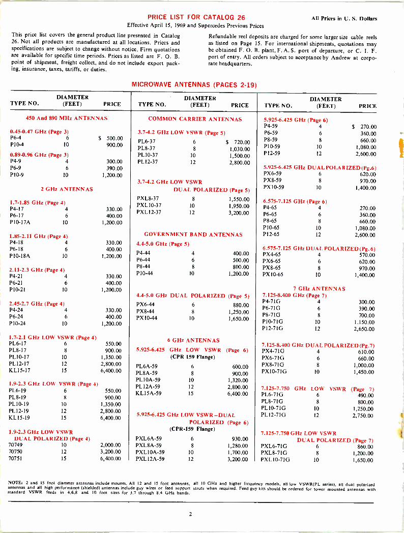
PRICE LIST FOR CATALOG 26 All Prices in U. S. Dollars Effective April 15, 1969 and Supercedes Previous Prices
This price list covers the general product line presented in Catalog 26. Not all products are manufactured at all locations. Prices and specifications are subject to change without notice. Firm quotations are available for specific time periods. Prices as listed are F. O. B. point of shipment, freight collect, and do not include export pack- ing, insurance, taxes, tariffs, or duties.
Refundable reel deposits are charged for some larger size cable reels as listed on Page 15. For international shipments, quotations may be obtained F. O. B. plant, F. A. S. port of departure, or C. I. F. port of entry. All orders subject to acceptance by Andrew at corpo- rate headquarters.
MICROWAVE ANTENNAS (PAGES 2-19)
DIAMETER TYPE NO. (FEET) PRICE
DIAMETER TYPE NO. (FEET) PRICE
DIAMETER TYPE NO. (FEET) PRICE
450 And 890 MHz ANTENNAS
0.45-0.47 GHz (Page 3)
COMMON CARRIER ANTENNAS
3.7-4.2 GHz LOW VSWR (Page 5)
5.925-6.425 GHz (Page 6) P4-59 4 $ 270.00 P6-59 6 360.00
P6-4 6 $ 500.00 P10-4 10 900.00
PL6-37 6 $ 720.00 PL8-37 8 1,030.00
P8-59 8 660.00 P10-59 10 1,080.00
0.89-0.96 GHz (Page 3) PL 10-37 10 1,500.00 P12-59 12 2,600.00 P4-9 4 300.00 PL I2-37 12 2,800.00 P6-9 6 390.00 5.925-6.425 GHz DUAL POLARIZED (Pg.6) P10-9 10 1,200.00 PX6-59 6 620.00
3.7-4.2 GHz LOW VSWR PX8-59 8 970.00 2 GHz ANTENNAS DUAL POLARIZED (Page 5)
PX 10-59 10 1,400.00
1.7-1.85 GHz (Page 4) P4-17 4 330.00 P6-17 6 400.00
PXL8-37 8 1,550.00 PXL 10-37 10 1,950.00 PXL 12-37 12 3,200.00
6.575-7.125 GHz (Page 6) P4-65 4 270.00 P6-65 6 360.00
P10 -17A 10 1,200.00 P8-65 8 660.00 P10-65 10 1,080.00
1.85-2.11 GHz (Page 4) GOVERNMENT BAND ANTENNAS P12-65 12 2,600.00 P4-18 4 330.00 4.4-5.0 GHz (Page 5) P6-18 6 400.00 P10 -18A 10 1,200.00
P4-44 4 400.00 P6-44 6 500.00
6.575-7.125 GHz DUAL POLARIZED (Pg. 6) PX4-65 4 570.00 PX6-65 6 620.00
2.11-2.3 GHz (Page 4) P4-21 4 330.00
P8-44 8 800.00 P10-44 10 1,200.00
PX8-65 8 970.00 PX 10-65 10 1,400.00
P6-21 6 400.00 P10-21 10 1,200.00 7 GHz ANTENNAS
4.4-5.0 GHz DUAL POLARIZED (Page 5) 7.125-8.400 GHz (Page 7)
2.45-2.7 GHz (Page 4) P4-24 4 330.00 P6-24 6 400.00 P10-24 10 1,200.00
PX6-44 6 880.00 PX8-44 8 1,250.00 PX 10-44 10 1,650.00
P4 -71G 4 300.00 P6 -71G 6 390.00 P8-71 G 8 700.00 P10 -71G 10 1.150.00 P12 -71G 12 2,650.00
1.7-2.1 GHz LOW VSWR (Page 4) PL6-17 6 550.00
6 GHz ANTENNAS 7.125-8.400 GHz DUAL POLARIZED (Pg.7)
PL8-17 8 900.00 5.925-6.425 GHz LOW VSWR (Page 6) PX4-71G 4 610.00 PL 10-17 10 1,350.00 (CPR 159 Flange) PX6-7IG 6 660.00 PL 12-17 12 2,800.00 PL6A-59 6 600.00 PX8-71G 8 1,000.00 KL15-17 15 6,400.00 PL8A-59 8 900.00 PX10-7IG 10 1,450.00
1.9-2.3 GHz LOW VSWR (Page 4) PL6-19 6 550.00 PL8-19 8 900.00
PL I OA -59 10 1,320.00 PL 12A-59 12 2,800.00 KL15A-59 15 6,400.00
7.125-7.750 GHz LOW VSWR (Page 7) PL6-71G 6 490.00
PL10-19 10 1,350.00 PL8-71G 8 800.00
PL12-19 12 2,800.00 PL10-71G 10 1,250.00
KL15-19 15 6,400.00 5.925-6.425 GHz LOW VSWR-DUAL PLI2-71G 12 2,750.00
POLARIZED (Page 6)
1.9-2.3 GHz LOW VSWR (CPR -159 Flange)
7.125-7.750GHz LOW VSWR DUAL POLARIZED (Page 4) PXL6A-59 6 930.00 DUAL POLARIZED (Page 7)
70749 10 2,000.00 PXL8A-59 8 1,280.00 PXL6-7IG 6 860.00 70750 12 3,200.00 PXL 10A-59 10 1,700.00 PXL8-71G 8 1,200.00 70751 15 6,400.00 PXL 12A-59 12 3,200.00 PXL10-71G 10 1,650.00
NOTE: 2 and 15 foot diameter antennas include mounts. All 12 and 15 foot antennas, all IO GHz and higher frequency models, all low VSWR(PL series), all dual polarized antennas and all high performance (shielded) antennas include guy wires or feed support struts when required. Feed guy kits should be ordered for tower mounted antennas with standard VSWR feeds in 4,6,8 and 10 foot sizes for 3.7 through 8.4 GHz bands.
2
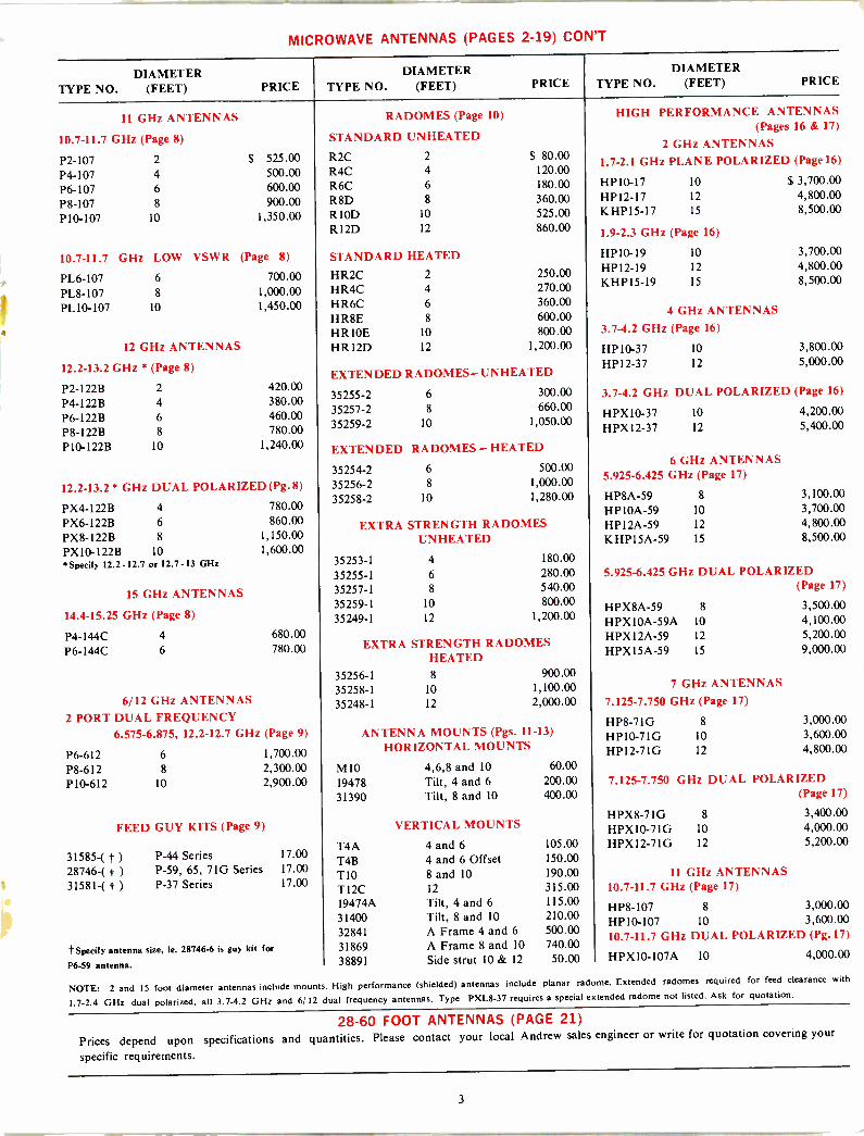
MICROWAVE ANTENNAS (PAGES 2-19) CON'T
DIAMETER TYPE NO. (FEET) PRICE
DIAMETER TYPE NO. (FEET) PRICE
DIAMETER TYPE NO. (FEET) PRICE
11 GHz ANTENNAS
10.7-11.7 GHz (Page 8)
P2-107 2
P4-107 4
P6-107 6
P8-107 8
P10-107 10
$ 525.00 500.00 600.00 900.00
1,350.00
10.7-11.7 GHz LOW VSWR (Page 8)
PL6-107 PL 8-107 PL10-107
6
8
10
12 GHz ANTENNAS
12.2-13.2 GHz * (Page 8)
P2 -122B 2
P4 -122B 4 P6 -122B 6
P8 -122B 8
P10 -122B 10
700.00 1,000.00 1,450.00
420.00 380.00 460.00 780.00
1,240.00
12.2-13.2* GHz DUAL POLARIZED (Pg.8)
PX4-122B 4
PX6-122B 6
PX8-I22B 8
PX10-122B 10 Specify 12.2-12.7 or 12.7-13 GHz
15 GHz ANTENNAS
14.4-15.25 GHz (Page 8)
P4 -144C 4
P6 -144C 6
780.00 860.00
1,150.00 1,600.00
680.00 780.00
6/12 GHz ANTENNAS 2 PORT DUAL FREQUENCY
6.575-6.875, 12.2-12.7 GHz (Page 9)
P6-612 6
P8-612 8
P10-612 10
1,700.00 2,300.00 2,900.00
FEED GUY KITS (Page 9)
31585-( t )
28746-( t )
31581-( t )
P-44 Series P-59, 65, 71G Series P-37 Series
t Specify antenna size, ie. 28746-6 is guy kit for
P6-59 antenna.
17.00 17.00 17.00
RADOMES (Page 10)
STANDARD UNHEATED
R2C 2
R4C R6C R8D R 10D RI2D
4
6
8
10
12
STANDARD HEATED
HR2C 2
HR4C HR6C H R8E HR10E HR I2D
4
6
8
10
12
$ 80.00 120.00 180.00 360.00 525.00 860.00
250.00 270.00 360.00 600.00 800.00
1,200.00
EXTENDED RADOMES-UNHEATED
35255-2 35257-2 35259-2
6
8
10
300.00 660.00
1,050.00
EXTENDED RADOMES- HEATED
35254-2 6
35256-2 8
35258-2 10
500.00 1,000.00 1,280.00
EXTRA STRENGTH RADOMES UNHEATED
35253-1 4
35255-1 6
35257-1 8
35259-1 10
35249-1 12
180.00 280.00 540.00 800.00
1,200.00
EXTRA STRENGTH RADOMES HEATED
35256-1 35258-1 35248-1
8
10
12
900.00 1,100.00 2,000.00
ANTENNA MOUNTS (Pgs. 11-13)
HORIZONTAL MOUNTS
M 10 4,6,8 and 10 60.00
19478 Tilt, 4 and 6 200.00
31390 Tilt, 8 and 10 400.00
T4A T4B TIO T12C 19474A 31400 32841 31869 38891
VERTICAL MOUNTS
4 and 6
4 and 6 Offset 8 and 10
12
Tilt, 4 and 6
Tilt, 8 and 10
A Frame 4 and 6
A Frame 8 and 10
Side strut 10 & 12
105.00 150.00 190.00 315.00 115.00 210.00 500.00 740.00 50.00
HIGH PERFORMANCE ANTENNAS (Pages 16 & 17)
2 GHz ANTENNAS
1.7-2.1 GHz PLANE POLARIZED (Page16)
HP10-17 10
HP12-17 12
KHP15-17 15
1.9-2.3 GHz (Page 16)
HP10-19 10
HP12-19 12
KHPI5-19 15
4 GHz ANTENNAS
3.7-4.2 GHz (Page 16)
HP10-37 10
HP12-37 12
$ 3,700.00 4,800.00 8,500.00
3,700.00 4,800.00 8,500.00
3,800.00 5,000.00
3.7-4.2 GHz DUAL POLARIZED (Page 16)
HPX 10-37 10 4,200.00 HPX12-37 12 5,400.00
6 GHz ANTENNAS 5.925-6.425 GHz (Page 17)
HP8A-59 8
HP I OA -59 10
HP12A-59 12
KHP15A-59 15
3,100.00 3,700.00 4,800.00 8,500.00
5.925-6.425 GHz DUAL POLARIZED (Page 17)
HPX8A-59 8 3,500.00 HPXIOA-59A 10 4,100.00 HPXI2A-59 12 5,200.00 HPXI5A-59 15 9,000.00
7 GHz ANTENNAS
7.12.5-7.750 GHz (Page 17)
HP8-71G 8
HP10-71G 10
HP12-71G 12
3,000.00 3,600.00 4,800.00
7.125-7.750 GHz DUAL POLARIZED (Page 17)
HPX8-71G 8 3,400.00 HPX10-71G 10 4,000.00 HPX12-71G 12 5,200.00
11 GHz ANTENNAS 10.7-11.7 GHz (Page 17)
HP8-107 8 3,000.00 H P10-107 10 3,600.00 10.7-11.7 GHz DUAL POLARIZED (Pg.17)
HPX10-107A 10 4,000.00
NOTE: 2 and IS foot diameter antennas include mounts. High performance (shielded) antennas include planar tadorne. Extended tadornes required for feed clearance with
1.7-2.4 GHz dual polarized, all 3.7-4.2 GHz and 6/ 12 dual frequency antennas. Type PXL8-37 requires a special extended radome not listed. Ask for quotation.
28-60 FOOT ANTENNAS (PAGE 21)
Prices depend upon specifications and quantities. Please contact your local Andrew sales engineer or write for quotation covering your
specific requirements.
3
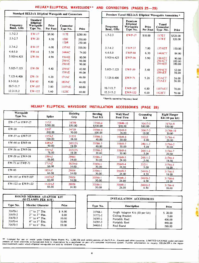
HELIAX 3- ELLIPTICAL WAVEGUIDE,<-., AND CONNECTORS (PAGES 25-29) Standard HELIAX Elliptical Waveguide and Connectors
Standard Elliptical
Frequency Waveguide Price Connector Band, GHz Type No. Per Foot Type No. Price
1.7-2.3 E\\ -17 $9.00 117E $280.00
2.5-2.7 EW-20 8.50 120E 250.00 12OR 250.00
3.7-4.2 EW-37 6.00 I37AE 100.00
4.4-5.0 EW-44 5.30 I44AC 74.00
5.925-6.425 EW-56 4.90 156AE 80.00 256AC 90.00 256AE 90.00
5.925-7.125 EW-59 4.40 159AC 42.00 159AE 46.00
7.125-8.400 E W-71 4.20 171 AC 46.00 8.5-10.0 EW-85 4.00 185AC 46.00
10.7-11.7 EW-107 3.80 1107AE 60.00 12.2-13.2 EW-122 3.60 I122C 60.00
Premium Tuned HELIAX Elliptical Waveguide Assemblies *
Premium Elliptical Tuned
Frequency Waveguide Price Connector Band, GHz Type No. Per Foot Type No. Price
1.7-2.3 EWP-17 $10.00 I17FT $320.00 117R 320.00
3.7-4.2 EWP-37 7.00 I37AET 110.00
4.4-5.0 EWP-44 6.30 I44ACT 84.00
5.925-6.425 EWP-56 5.90 156AET 90.00 256ACT 100.00 256AET 100.00
5.925-7.125 EWP-59 5.40 I59ACT 52.00 I59AET 56.00
7.125-8.400 FWP- 7 I 5.20 I7IACT 56.00 I71AET 56.00
10.7-I1.7 EWP-107 4.80 II07AET 70.00 12.2-13.2 EWP-122 4.60 II22CT 70.00
*Specify operating frequency band
HELIAX R ELLIPTICAL WAVEGUIDE INSTALLATION ACCESSORIES (PAGE 28)
Waveguide Type No. Splice
Hoisting Grip
Bending Tool Kit
Wall/ Roof Feed Thru
Grounding Kit
Rigid Hanger Kit (10 per kit)
EW-17 or EWP-17 1177 34759 33586-4 35849-10 30417-5 31766-9 $280.00 $30.00 $100.00 $48.00 $10.00 $30.00
EW-20 120Z 34759 33586-4 35849-9 30417-3 31766-10 260.00 30.00 100.00 36.00 10.00 30.00 EW-37 or EWP-37 I37AZ 31535 33586-3 35849-8 33212 31760-4
100.00 18.00 40.00 30.00 6.00 20.00 EW-44 or EWP-44 144\7 _24312\ 33586-3 35849-7 24811-2 31766-2 90.00 18.00 40.00 30.00 5.00 20.00 EW-56 or EWP-56 I56AZ 24312.\ 33586-2 35849-6 24811-2 31766-7 78.00 18.00 30.00 30.00 5.00 20.00 EW-59 or EWP-59 159AZ 29961 33586-2 35849-5 2481 I-2 31766-1
66.00 14.00 30.00 28.00 5.00 18.00 EW-71 or EWP-71 171.ÁZ 1925613 33856-1 35849-4 33211 31766-3
66.00 14.00 30.00 28.00 5.00 18.00 EW-85 185AZ 29958 33586-1 35849-3 24810-2 31766-5 66.00 14.00 30.00 28.00 4.50 18.00 EW-107 or EWP-107 1107AZ 29958 33586-1 35849-2 24810-2 31766-6 66.00 14.00 30.00 28.00 4.50 18.00 EW-122 or EWP-122 1122 \L 29958 33586-1 35849-1 24810-2 31766-8 66.00 14.00 30.00 28.00 4.50 18.00
ROUND MEMBER ADAPTOR KIT (10 CLAMPS PER KIT)
Type No. Member Diameter Price
31670-1 1" to 2" Dia. $ 8.00 31670-2 2" to 3" Dia. 8.00 31670-3 3" to 4" Dia. 10.00 31670-4 4" to 5" Dia. 10.00 31670-5 5" to 6" Dia. 10.00
INSTALLATION ACCESSORIES
Type No. Description Price
31768-1 Angle Adaptor Kit (10 per kit) $ 20.00 31771-1 Ceiling Bracket 5.00 34397-1 Portable Reel 400.00 34397-3 Portable Reel 440.00 34405-1 Reel Stand 280.00
** Licensed for use or resale under United States Patent No. 3,200,356 and certain patents of the U.S.A., Canada and other countries. LIMITED LICENSE under pertinent patents of most countries in Europe and Asia to importation by a purchaser as part of a complete microwave system. Further information on inquiry. HELIAX® is the regist- ered trademark under which elliptical waveguides are sold by Andrew Corporation.
4

RIGID RECTANGULAR WAVEGUIDE AND COMPONENTS (PAGES 30-32) Order waveguide by Andrew type number shown in red. Suffix on type number of straight sections and flex -twist sections indicates length in inches. When ordering variable lengths be sure to specify length in inches. Price charged to next whole foot.
STANDARD RECTANGULAR WAVEGUIDE WITH CPR FLANGES (PAGE 30)*
DESCRIPTION WR -229
3.30-4.90 GHz WR -187
3.95-5.85 GHz WR -159
4.9-7.05 GHz WR -137
5.8-8.2 GHz WR -112
7.05-10.0 GHz WR -90
8.20-12.40 GHz
5 ft. straight section 54055-60 55234-60 54749-60 54390-60 55172-60 54396-60 $172.00 $100.00 $ 80.00 $ 58.00 $ 58.00 $ 52.00
10 ft. straight section 54055-120 55234-120 54749-120 54390-120 55172-120 54396-120 225.00 130.00 110.00 70.00 70.00 64.00
Special lengths 54055-( ) 55234-( ) 54749-( ) 54390-( ) 55172-( ) 54396-( ) 112.00 90.00 80.00 48.00 48.00 42.00
+12.60/ft. +5.00/ft. +4.00/ft. +3.00/ft. +3.00/ft. +3.00/ft. 1 ft. flex -twist section 54059-12 55235-12 54756-12 54395-12 55233-12 54401-12
140.00 140.00 125.00 90.00 90.00 70.00 2 ft. flex -twist section 54059-24 55235-24 54756-24 54395-24 55233-24 54401-24
160.00 160.00 135.00 100.00 100.00 80.00 3 ft. flex -twist section 54059-36 55235-36 54756-36 54395-36 55233-36 54401-36
170.00 170.00 150.00 110.00 110.00 90.00 5 ft. flex -twist section - - - 54395-60 - -
- - - 130.00 - - 90° E plane bend 55229-229 55229-187 55229-159 55229-137 55229-112 55229-90
155.00 90.00 75.00 60.00 58.00 56.00 90° H plane bend 55230-229 55230-187 55230-159 55230-137 55230-112 55230-90
155.00 90.00 75.00 60.00 58.00 56.00 90° twist 55231-229 55231-187 55231-159 55231-137 55231-112 55231-90
160.00 92.00 90.00 60.00 70.00 85.00 Pressure inlet 55674-229 55674-187 55674-159 55674-137 55674-112 55674-90
50.00 50.00 40.00 40.00 40.00 40.00
Pressure window 55001-229 55001-187 55001-159 55001-137 55001-112 55001-90 20.00 20.00 20.00 20.00 20.00 20.00
Field flange 56045-229 56045-187 56045-159 56045-137 56045-112 56045-90 65.00 65.00 50.00 40.00 40.00 40.00
Hardware kit 55219-229 55219-187 55219-159 55219-137 55219-112 55219-90 6.00 5.00 5.00 5.00 5.00 5.00
STANDARD RECTANGULAR WAVEGUIDE WITH CHOKE/COVER FLANGES (PAGE 31)'`
DESCRIPTION WR -187
3.95-5.85 GHz WR -137
5.8-8.2 GHz WR -112
7.05-10.0 GHz WR -90
8.20-12.40 GHz WR -75
10.0-15.0 GHz WR -62
12.4-18.0 GHz
5 ft. straight section 52080-60 19065-60 19045-60 19051-60 51741-60 53210-60 $ 74.00 $ 48.00 $ 45.00 $ 45.00 $ 50.00 $ 45.00
10 ft. straight section 52080-120 19065-120 19045-120 19051-120 51741-120 53210-120 100.00 60.00 60.00 60.00 60.00 60.00
Special lengths 52080-( ) 19065-( ) 19045-i i 19051-( ) 51741-( ) 53210-( )
60.00 38.00 38.00 36.00 36.00 34.00 +5.00/ft. +3.00/ft. +3.00/ft. +3.00/ft. +3.00/ft. +3.00/ft.
I ft. flex -twist section 52095-12 19075-12 51727-12 51737-12 51747-12 53215-12 110.00 65.00 65.00 65.00 88.00 110.00
2 ft. flex -twist section 52095-24 19075-24 51727-24 51737-24 51747-24 53215-24 132.00 75.00 75.00 75.00 105.00 120.00
3 ft. flex -twist section 52095-36 19075-36 51727-36 51737-36 51747-36 53215-36 146.00 85.00 85.00 85.00 115.00 130.00
5 ft. flex -twist section - 19075-60 - - - - - 100.00 - - - - 90° E plane bend 55220-187 55220-137 55220-112 55220-90 55220-75 55220-62
70.00 50.00 48.00 46.00 42.00 42.00 90° H plane bend 55221-187 55221-137 55221-112 55221-90 55221-75 55221-62
70.00 50.00 48.00 46.00 42.00 42.00
90° twist 55222-187 55222-137 55222-112 55222-90 55222-90 55222-62 72.00 50.00 60.00 75.00 64.00 45.00
Pressure inlet 55675-187 55675-137 55675-112 55675-90 55675-75 55675-62 64.00 64.00 50.00 40.00 40.00 40.00
Pressure window 55000-187 55000-137 55000-112 55000-90 55000-75 55000-62 16.00 16.00 16.00 16.00 16.00 16.00
Field choke flange 53015-187 53015-137 53015-112 53015-90 53015-75 53015-62 72.00 40.00 60.00 100.00 100.00 70.00
Field cover flange 53025-187 53025-137 53025-1122 53025-90 53025-75 53025-62 64.00 30.00 40.00 100.00 100.00 65.00
Hardware kit 55224-187 55224-137 55224-112 55224-90 55224-75 55224-62 3.00 2.00 2.00 3.00 3.00 3.00
5
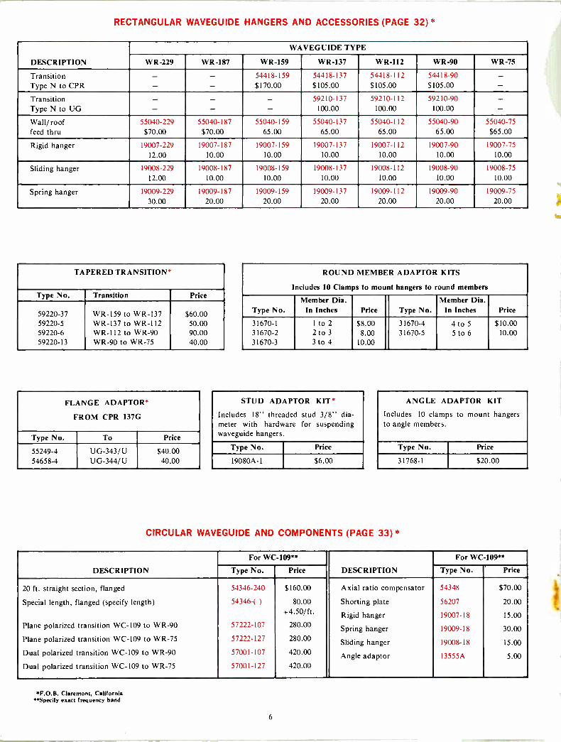
RECTANGULAR WAVEGUIDE HANGERS AND ACCESSORIES (PAGE 32)*
DESCRIPTION
WAVEGUIDE TYPE
WR -229 WR -187 WR -159 WR -137 WR -112 WR -90 WR -75
Transition - - 54418-159 54418-137 54418-112 54418-90 - Type N to CPR - - $170.00 $105.00 $105.00 $105.00 - Transition - - - 59210-137 59210-112 59210-90 - Type N to UG - - - 100.00 100.00 100.00 - Wall/roof 55040-229 55040-187 55040-159 55040-137 55040-112 55040-90 55040-75 feed thru $70.00 $70.00 65.00 65.00 65.00 65.00 $65.00
Rigid hanger 19007-229 19007-187 19007-159 19007-137 19007-112 19007-90 19007-75
12.00 10.00 10.00 10.00 10.00 10.00 10.00
Sliding hanger 19008-229 19008-187 19008-159 19008-137 19008-11_2 19008-90 19008-75
12.00 10.00 10.00 10.00 10.00 10.00 10.00
Spring hanger 19009-229 19009-187 19009-159 19009-137 19009-112 19009-90 19009-75
30.00 20.00 20.00 20.00 20.00 20.00 20.00
TAPERED TRANSITION*
Type No. Transition Price
59220-37 WR -159 to WR -l37 $60.00 59220-5 WR -137 to WR -I12 50.00 59220-6 WR -I12 to WR -90 90.00 59220-13 WR -90 to WR -75 40.00
FLANGE ADAPTOR*
FROM CPR 137G
Type No. To Price
55249-4 54658-4
UG-343/U UG-344/U
$40.00 40.00
ROUND MEMBER ADAPTOR KITS
Includes 10 Clamps to mount hangers to round members
Member Dia. Member Dia. Type No. In Inches Price Type No. In Inches Price
31670-1 Ito 2 $8.00 31670-4 4 to 5 $10.00 31670-2 2 to 3 8.00 31670-5 5 to 6 10.00 31670-3 3 to 4 10.00
STUD ADAPTOR KIT*
Includes 18" threaded stud 3/8" dia- meter with hardware for suspending waveguide hangers.
Type No. Price
19080A-1 $6.00
ANGLE ADAPTOR KIT
Includes 10 clamps to mount hangers to angle members.
Type No. Price
31768-1 $20.00
CIRCULAR WAVEGUIDE AND COMPONENTS (PAGE 33)
DESCRIPTION
For WC -109**
DESCRIPTION
For WC -109**
Type No. Price Type No. Price
20 ft. straight section, flanged 54346-240 $160.00 Axial ratio compensator 54348 $70.00
Special length, flanged (specify length) 54346-( ) 80.00 Shorting plate 56207 20.00 + 4.50/ft. Rigid hanger 19007-18 15.00
Plane polarized transition WC -109 to WR -90 57222-107 280.00 Spring hanger 19009-18 30.00 Plane polarized transition WC -109 to WR -75 57222-127 280.00 Sliding hanger 19008-18 15.00
Dual polarized transition WC -109 to WR -90 57001-107 420.00 Angle adaptor 13555A 5.00 Dual polarized transition WC -109 to WR -75 57001-127 420.00
*F.O.B. Claremont, California *Specify exact frequency band
6
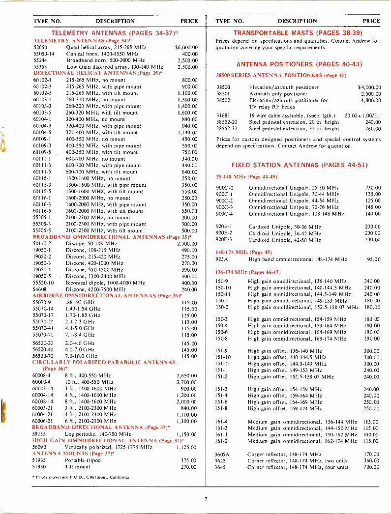
TYPE NO. DESCRIPTION PRICE TYPE NO. DESCRIPTION PRICE
TELEMETRY ANTENNAS (PAGES 34-37)* TELEMETRY ANTENNAS (Page 34)* 52650 Quad helical array, 215-265 MHz $6,000.00 55050-14 Conical horn, 1400-1550 MHz 400.00 55244 Broadband horn, 500-2000 MHz 2,500.00 55353 Low Gain disk/rod array, 130-140 MHz 2,500.00 DIRECTIONAL HELICAL ANTENNAS (Page 35)* 60102-1 215-265 MHz, no mount 800.00 60102-3 215-265 MHz, with pipe mount 900.00 60102-5 215-265 MHz, with tilt mount 1,100.00 60103-1 260-320 MHz, no mount 1,300.00 60103-3 260-320 MHz, with pipe mount 1,400.00 60103-5 260-320 MHz, with tilt mount 1,600.00 60104-1 320-400 MHz, no mount 840.00 60104-3 320-400 MHz, with pipe mount 940.00 60104-5 320-400 MHz, with tilt mount 1,140.00 60109-1 400-550 MHz, no mount 450.00 60109-3 400-550 MHz, with pipe mount 550.00 60109-5 400-550 MHz, with tilt mount 750.00 60111-1 600-700 MHz, no mount 340.00 60111-3 600-700 MHz, with pipe mount 440.00 60111-5 600-700 MHz, with tilt mount 640.00 60115-1 1300-1600 MHz, no mount 250.00 60115-3 1300-1600 MHz, with pipe mount 350.00 60115-5 1300-1600 MHz, with tilt mount 550.00 60116-1 1600-2000 MHz, no mount 250.00 60116-3 1600-2000 MHz, with pipe mount 350.00 60116-5 1600-2000 MHz, with tilt mount 550.00 55305-1 2100-2300 MHz, no mount 200.00 55305-3 2100-2300 MHz, with pipe mount 300.00 55305-5 2100-2300 MHz, with tilt mount 500.00 BROADBAND OMNIDIRECTIONAL ANTENNAS (Page 35)* 50170-2 Discage, 50-108 MHz 2,500.00 19050-1 Discone, 108-215 MHz 490.00 19050-2 Discone, 215-420 MHz 275.00 19050-3 Discone, 420-1000 MHz 270.00 19050-4 Discone, 550-1500 MHz 390.00 19050-5 Discone, 1300-2400 MHz 300.00 55520-10 Biconical dipole, 1000-4000 MHz 400.00 54608 Discone, 4200-7500 MHz 240.00 AIRBORNE OMNIDIRECTIONAL ANTENNAS (Page 36)* 55070-9 55070-14 55070-17 55070-21 55070-44 55070-71
.88-.92 GHz 1.43-1.54 GHz 1.70-1.85 GHz 2.1-2.3 GHz 4.4-5.0 GHz 7.1-8.4 GHz
56520-20 2.0-4.0 GHz 56520-40 4.0-7.0 GHz 56520-70 7.0-10.0 GHz CIRCULARLY POLARIZED PARABOLIC ANTENNAS
(Page 36)* 60008-4 8 ft., 400-550 MHz 60010-4 10 ft., 400-550 MHz 60003-14 3 ft., 1400-1600 MHz 60004-14 4 ft., 1400-1600 MHz 60008-14 8 ft., 1400-1600 MHz 60003-21 3 ft., 2100-2300 MHz 60004-21 4 ft., 2100-2300 MHz 60006-21 6 ft., 2100-2300 MHz BROADBAND DIRECTIONAL ANTENNA (Page 37)* 59135 Log periodic, 140-750 MHz 1,150.00 HIGH GAIN OMNIDIRECTIONAL ANTENNA (Page 37)* 56090 Vertically polarized, 1725-1775 MHz 1,125.00
115.00 115.00 115.00 115.00 115.00 115.00
145.00 145.00 145.00
ANTENNA MOUNTS (Page 37)* 51935 Portable tripod 51930 Tilt mount
Prices shown are F.O.B., Claremont, California
2,650.00 3,700.00
900.00 1,200.00 2,000.00
840.00 1,100.00 1,300.00
375.00 270.00
TRANSPORTABLE MASTS (PAGES 38-39) Prices depend on specifications and quantities. Contact Andrew for quotation covering your specific requirements.
ANTENNA POSITIONERS (PAGES 40-43)
38500 SERIES ANTENNA POSITIONERS (Page 41)
38500 Elevation/azimuth positioner $ 4,000.00 38501 Azimuth only positioner 2,500.00 38502 Elevation/azimuth positioner for 4,800.00
TV relay RF heads
31681 19 wire cable assembly, (spec. lgth.) 20.00+1.00/ft. 38552-20 Steel pedestal extension, 20 in. height 240.00 38552-32 Steel pedestal extension, 32 in. height 260.00
Prices for custom designed positioners and special control systems depend on specifications. Contact Andrew for quotation.
FIXED STATION ANTENNAS (PAGES 44-51)
25-148 MHz (Page 44-45)
900C-0 Omnidirectional Unipole, 25-30 MHz 230.00 900C-1 Omnidirectional Unipole, 30-44 MHz 135.00 900C-2 Omnidirectional Unipole, 44-54 MHz 125.00 900C-3 Omnidirectional Unipole, 72-76 MHz 145.00 900C-4 Omnidirectional Unipole, 108-148 MHz 140.00
920E-1 Cardioid Unipole, 30-36 MHz 230.00 920E-2 Cardioid Unipole, 36-42 MHz 230.00 920E-3 Cardioid Unipole, 42-50 MHz 230.00
148-174 MHz (Page 45) 925A High band omnidirectional 148-174 MHz 95.00
136-174 MHz (Pages 46-47)
150-9 High gain omnidirectional, 136-140 MHz 240.00 150-10 High gain omnidirectional, 140-144.5 MHz 240.00 150-11 High gain omnidirectional, 144.5-149 MHz 240.00 150-1 High gain omnidirectional, 149-153 MHz 180.00 150-2 High gain omnidirectional, 152.5-158.07 MHz 180.00
150-3 High gain omnidirectional, 154-159 MHz 180.00 150-4 High gain omnidirectional, 159-164 MHz 180.00 150-6 High gain omnidirectional, 164-169 MHz 190.00 150-8 High gain omnidirectional, 169-174 MHz 190.00
151-9 High gain offset, 136-140 MHz 300.00 151-10 High gain offset, 140-144.5 MHz 300.00 151-11 High gain offset, 144.5-149 MHz 300.00 151-1 High gain offset, 149-153 MHz 240.00 151-2 High gain offset, 152.5-158.07 MHz 240.00
151-3 High gain offset, 154-159 MHz 240.00 151-4 High gain offset, 159-164 MHz 240.00 151-6 High gain offset, 164-169 MHz 250.00 151-8 High gain offset, 169-174 MHz 250.00
161-4 Medium gain omnidirectional, 136-144 MHz 115.00 161-3 Medium gain omnidirectional, 144-150 MHz 115.00 161-1 Medium gain omnidirectional, 150-162 MHz 100.00 161-2 Medium gain omnidirectional, 162-174 MHz 115.00
3605A Corner reflector, 148-174 MHz 170.00 3625 Corner reflector, 148-174 MHz, two units 360.00 3645 Corner reflector, 148-174 MHz, four units 700.00
7

TYPE NO. DESCRIPTION PRICE TYPE NO. DESCRIPTION PRICE
FIXED STATION ANTENNAS (PAGES 44-51)
406-420 & 450-470 MHz (Pages 48-49)
460A-1 High gain omnidirectional, 450-460 MHz 460A-2 High gain omnidirectional, 460-470 MHz 465-1 High gain omnidirectional, 450-460 MHz 465-2 High gain omnidirectional, 460-470 MHz
461A-1 461A-2 466-1 466-2
High gain offset, 450-460 MHz High gain offset, 460-470 MHz High gain offset, 450-460 MHz High gain offset, 460-470 MHz
116 Yagi antenna, 450-470 MHz 117 Yagi antenna, 450-470 MHz, two units
3608D Corner reflector, 406-420 MHz 3606D Corner reflector, 450-470 MHz 3626D Corner reflector, 450-470 MHz, two units 3646D Corner reflector, 450-470 MHz, four units
ACCESSORIES (Page 50) MOUNTING CLAMPS (Set of 2)
20898 For series 920E to 3/4" -3" OD pipe 21208 For series 925A to 1" OD pipe 15681 All series to 3/4" - 3" OD pipe
14672-3 29291-3 30150
All series to 7/8" angle member All series to 1" - 3" OD pipe For series 161 to 1-3/4" OD pipe
SIDE MOUNT KITS
31553 For types 150, 151, 465, 466 31554 For types 161, 460A, 461A
JUMPER CABLES
25832 1/2" foam HELIAX cable, N plugs, 6 feet 25833 1/2" foam HELIAX cable, UHF plugs, 6 feet 25834 1/2" foam HELIAX cable, UHF -N plug, 6 ft.
16253-21 16253-23 16253-24
RG8A/U, N plugs, 4 feet RG8A/U, UHF plugs, 4 feet RG8A/U, UHF -N plug, 4 feet
$220.00 220.00 350.00 350.00
250.00 250.00 420.00 420.00
100.00 240.00
150.00 125.00 270.00 530.00
17.00 8.00
18.00
20.00 10.00 12.00
90.00 60.00
20.00 18.00 19.00
9.00 9.00 9.00
SOLID DIELECTRIC CABLES (PAGE 51) 10791-1 RG8A/U cable 0.30/ft. 10791-7 RG17/U cable 1.120/ft.
FITTINGS
10804-36 10804-34 10804-11 10804-9 10804-10 10804-31
10805-1 10805-6 10805-5 10805-4 10805-11 10805-12
12418-1 12418-3 12418-5 12418-12
N cable plug, RG8A/U N cable jack, RG8A/U N junction, RG8A/U N junction, RG8A/U N right angle connector, RG8A/U N panel receptacle, RG8A/U
UHF cable plug, RG8A/U UHF juction, RG8A/U UHF right angle connector, RG8A/U UHF tee connector, RG8A/U Adaptor, UHF jack -N plug, RG8A/U Apaptor, UHF plug -N jack, RG8A/U
LC cable plug, RG17/U LC junction RG17/U N cable plug, RG 17/ U
UHF cable plug, RG17/U
3.00 3.00 4.00 4.50 5.50 2.50
2.00 3.00 6.00 6.00 5.00 4.00
16.00 15.00 10.00 16.00
FOAM DIELECTRIC HELIAX FLEXIBLE COAXIAL CABLE' (PAGES 54-61)
See Page 15 for Shipping Reel Information
1/2" SUPERFLEXIBLE HELIAX COAXIAL CABLE (Page 54)
FSJ4-50 1/2", 50 ohm, jacketed $1.00/ft.
CONNECTORS FOR 1/2" SUPERFLEXIBLE CABLE (Page 54)
36723 N plug 25.00 36722 General Radio plug 25.00
1/4" FOAM DIELECTRIC COPPER HELIAX CABLE (Page 55) FH1-50 1/4", 50 ohm 0.34/ft. FHJ1-50 1/4", 50 ohm, jacketed 0.36/ft.
CONNECTORS FOR 1/4" FOAM CABLE (Page 55) 41U UHF jack 8.00 41P UHF plug 8.00 41N N jack 8.00 41W N plug 8.00 41 WT TNC plug 8.00 13212-2 End terminal adaptor (use with 41W) 10.00
3/8" FOAM DIELECTRIC COPPER HELIAX CABLE (Page 55) FH2-50A 3/8", 50 ohm 0.50/ft. FHJ2-50A 3/8", 50 ohm, jacketed 0.52/ft.
CONNECTORS FOR 3/8" FOAM CABLE (Page 55) 42U UHF jack 10.00 42P UHF plug 10.00 42N N jack 10.00 42W N plug 10.00 42WT TNC plug 10.00 13212-2 End terminal adaptor (use with 42W) 10.00
1/2" FOAM DIELECTRIC HELIAX CABLE (Page 56) FH4-50B 1/2", 50 ohm, copper 0.62/ft. FHJ4-50B 1/2", 50 ohm, copper, jacketed 0.66/ft. FH4-75 1/2", 75 ohm, copper 0.62/ft. FHJ4-75 1/2", 75 ohm, copper, jacketed 0.66/ft. FLJ4-50B 1/2", 50 ohm, aluminum, jacketed 0.60/ft.
CONNECTORS FOR 1/2" 50 ohm, COPPER (Page 57) 44AR 7/8" EIA flange 24.00 44AZ Splice 24.00 44AM LC plug 24.00 44AL LC jack 24.00 44AP UHF plug 6.00 44AU UHF jack 6.00 44AW N plug 7.00 44AN N jack 7.00 44AT End terminal 24.00 44AJ HN plug 24.00
CONNECTORS FOR 1/2", 75 ohm, COPPER (Page 57) 44AU-75 UHF jack 6.00 44AW-75 N plug 7.00 44AN-75 N jack 7.00
CONNECTORS FOR 1/2", 50 ohm, ALUMINUM (Page 57) 44AR-3 7/8" EIA flange 24.00 44AP-3 UHF plug 6.00 44AU-3 UHF jack 6.00 44AW-3 N plug 7.00 44AN-3 N jack 7.00
COMPONENTS FOR 1/2", 50 ohm, CABLE (Page 57) 1260A 7/8" EIA gas barrier 30.00
S These cables and connectors are proprietary products of Andrew Corporation manufactured under patents issued and pending. HELIAX® is the registered trade- mark under which coaxial cables are sold by Andrew Corporation.
8
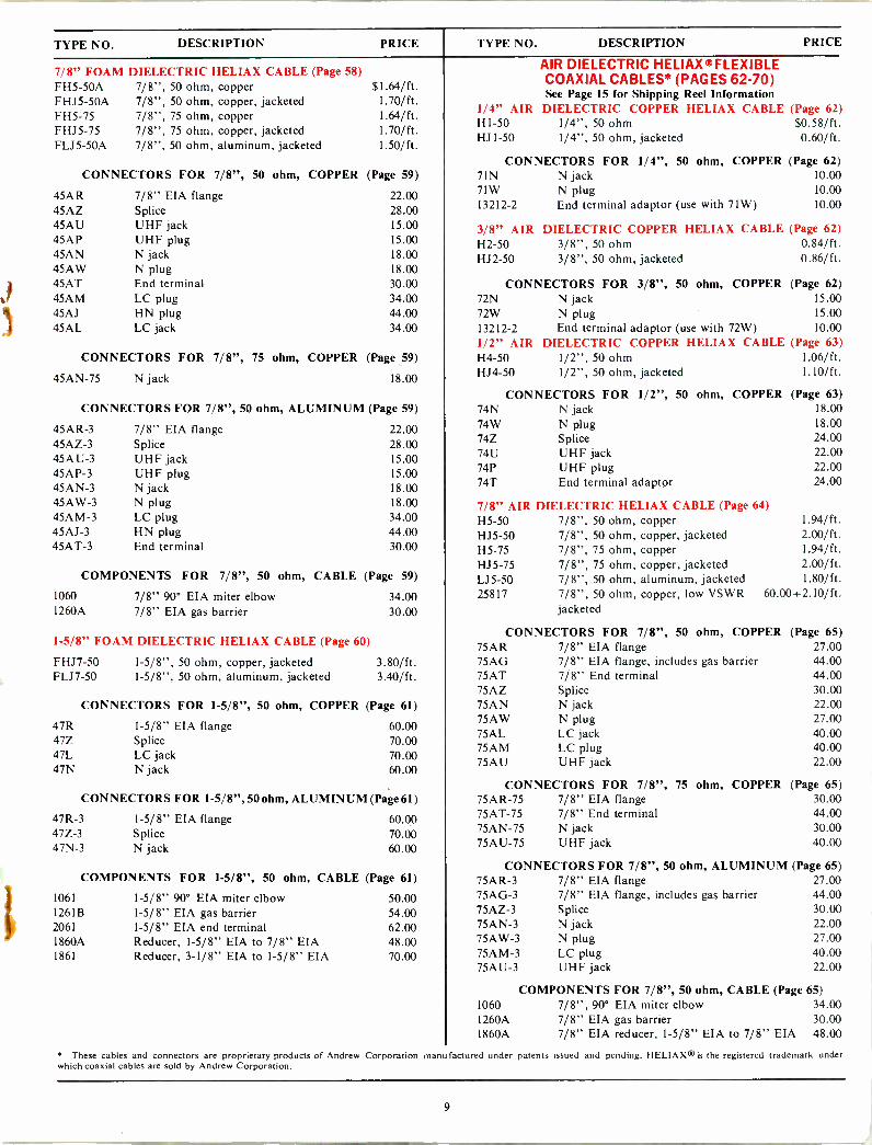
TYPE NO. DESCRIPTION PRICE TYPE NO. DESCRIPTION PRICE
7/8" FOAM DIELECTRIC HELIAX CABLE (Page 58) FH5-50A 7/8", 50 ohm, copper $1.64/ft. FHJ5-50A 7/8", 50 ohm, copper, jacketed 1.70/ft. FH5-75 7/8", 75 ohm, copper FHJ5-75 7/8", 75 ohm, copper, jacketed FLJ5-50A 7/8", 50 ohm, aluminum, jacketed
1.64/ft. 1.70/ft. 1.50/ ft.
CONNECTORS FOR 7/8", 50 ohm, COPPER (Page 59)
45AR 45AZ 45A U 45AP 45AN 45AW 45AT 45AM 45AJ 45AL
7/8" EIA flange Splice UHF jack UHF plug N jack N plug End terminal LC plug HN plug LC jack
22.00 28.00 15.00 15.00 18.00 18.00 30.00 34.00 44.00 34.00
CONNECTORS FOR 7/8", 75 ohm, COPPER (Page 59)
45AN-75 N jack 18.00
CONNECTORS FOR 7/8", 50 ohm, ALUMINUM (Page 59)
45AR-3 45AZ-3 45A U-3 45AP-3 45AN-3 45AW-3 45AM-3 45AJ-3 45AT-3
7/8" EIA flange Splice UHF jack UHF plug N jack N plug LC plug HN plug End terminal
22.00 28.00 15.00 15.00 18.00 18.00 34.00 44.00 30.00
COMPONENTS FOR 7/8", 50 ohm, CABLE (Page 59)
1060 7/8" 90° EIA miter elbow 34.00 1260A 7/8" EIA gas barrier 30.00
1-5/8" FOAM DIELECTRIC HELIAX CABLE (Page 60)
FHJ7-50 1-5/8", 50 ohm, copper, jacketed 3.80/ft. FLJ7-50 1-5/8", 50 ohm, aluminum, jacketed 3.40/ft.
47R 47Z 47L 47N
CONNECTORS FOR 1-5/8", 50 ohm, COPPER (Page 61)
1-5/8" EIA flange Splice LC jack N jack
60.00 70.00 70.00 60.00
CONNECTORS FOR 1-5/8", 50 ohm, ALUMINUM (Page 61)
47R-3 47Z-3 47N-3
1-5/8" EIA flange Splice N jack
60.00 70.00 60.00
COMPONENTS FOR 1-5/8", 50 ohm, CABLE (Page 61)
1061 1-5/8" 90° EIA miter elbow 1261B 1-5/8" EIA gas barrier 2061 1-5/8" EIA end terminal 1860A Reducer, 1-5/8" EIA to 7/8" EIA 1861 Reducer, 3-1/8" EIA to 1-5/8" EIA
50.00 54.00 62.00 48.00 70.00
AIR DIELECTRIC HELIAX ®FLEXIBLE COAXIAL CABLES* (PAGES 62-70) See Page 15 for Shipping Reel Information
1/4" AIR DIELECTRIC COPPER HELIAX CABLE (Page 62) H1-50 1/4", 50 ohm $0.58/ft. HJ1-50 1/4", 50 ohm, jacketed 0.60/ft.
CONNECTORS FOR 1/4", 50 ohm, 71N N jack 71W N plug 13212-2 End terminal adaptor (use with 71W)
COPPER (Page 62) 10.00 10.00 10.00
3/8" AIR DIELECTRIC COPPER HELIAX CABLE (Page 62) H2-50 3/8", 50 ohm 0.84/ft. HJ2-50 3/8", 50 ohm, jacketed 0.86/ft.
CONNECTORS FOR 3/8", 50 ohm, COPPER (Page 62) 72N N jack 15.00
72W N plug 15.00 13212-2 End terminal adaptor (use with 72W) 10.00 1/2" AIR DIELECTRIC COPPER HELIAX CABLE (Page 63) H4-50 1/2", 50 ohm 1.06/ft. HJ4-50 1/2", 50 ohm, jacketed 1.10/ft.
CONNECTORS FOR 1/2", 50 ohm, COPPER 74N N jack 74W N plug 74Z Splice 74U UHF jack 74P UHF plug 74T End terminal adaptor
7/8" AIR DIELECTRIC HELIAX CABLE (Page 64) H5-50 7/8", 50 ohm, copper HJ5-50 7/8", 50 ohm, copper, jacketed H5-75 7/8", 75 ohm, copper HJ5-75 7/8", 75 ohm, copper, jacketed LJ5-50 7/8", 50 ohm, aluminum, jacketed 25817
(Page 63) 18.00 18.00 24.00 22.00 22.00 24.00
1.94/ft. 2.00/ft. 1.94/ft. 2.00/ft. 1.80/ft.
7/8", 50 ohm, copper, low VSWR 60.00+2.10/ft. jacketed
CONNECTORS FOR 7/8", 50 ohm, COPPER (Page 65) 75AR 7/8" EIA flange 27.00 75AG 7/8" EIA flange, includes gas barrier 44.00 75AT 7/8" End terminal 44.00 75AZ Splice 30.00 75AN N jack 22.00 75AW N plug 27.00 75AL LC jack 40.00 75AM LC plug 40.00 75AU UHF jack 22.00
CONNECTORS FOR 7/8", 75 75AR-75 7/8" EIA flange 75AT-75 7/8" End terminal 75AN-75 N jack 75AU-75 UHF jack
ohm, COPPER (Page 65) 30.00 44.00 30.00 40.00
CONNECTORS FOR 7/8", 50 ohm, ALUMINUM (Page 65) 75AR-3 7/8" EIA flange 75AG-3 7/8" EIA flange, includes gas barrier 75AZ-3 75AN-3 75AW-3 75AM-3 75AU-3
Splice N jack N plug LC plug UHF jack
27.00 44.00 30.00 22.00 27.00 40.00 22.00
COMPONENTS FOR 7/8", 50 ohm, CABLE (Page 65) 1060 7/8", 90° EIA miter elbow 34.00 1260A 7/8" EIA gas barrier 30.00 1860A 7/8" EIA reducer, 1-5/8" EIA to 7/8" EIA 48.00
These cables and connectors are proprietary products of Andrew Corporation manu factured under patents issued and pending. HELIAX is the registered trademark under which coaxial cables are sold by Andrew Corporation.
9
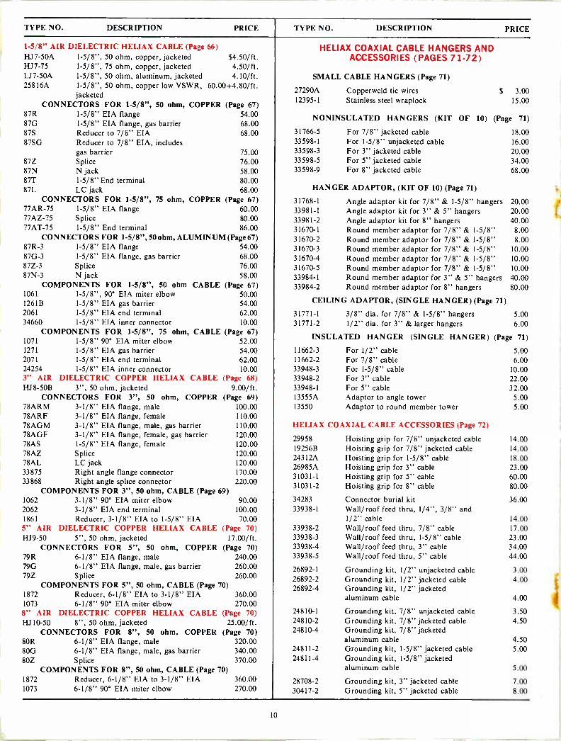
TYPE NO. DESCRIPTION PRICE TYPE NO. DESCRIPTION PRICE
1-5/8" AIR DIELECTRIC HELIAX CABLE (Page 66) HJ7-50A 1-5/8", 50 ohm, copper, jacketed $4.50/ft. HJ7-75 1-5/8", 75 ohm, copper, jacketed 4.50/ft. LJ7-50A 1-5/8", 50 ohm, aluminum, jacketed 4.10/ft. 25816A 1-5/8", 50 ohm, copper low VSWR, 60.00+4.80/ft.
jacketed CONNECTORS FOR 1-5/8", 50 ohm, COPPER (Page 67)
87R 1-5/8" EIA flange 54.00 87G 1-5/8" EIA flange, gas barrier 68.00 87S Reducer to 7/8" EIA 68.00 87SG Reducer to 7/8" EIA, includes
gas barrier 87Z Splice 87N N jack 87T 1-5/8" End terminal 87L LC jack
CONNECTORS FOR 1-5/8", 75 ohm, 77AR-75 1-5/8" EIA flange 77AZ-75 Splice 77AT-75 1-5/8" End terminal
75.00 76.00 58.00 80.00 68.00
COPPER (Page 67) 60.00 80.00 86.00
CONNECTORS FOR 1-5/8", 50 ohm, ALUMINUM (Page 67) 87R-3 1-5/8" EIA flange 54.00 87G-3 1-5/8" EIA flange, gas barrier 68.00 87Z-3 Splice 76.00 87N-3 N jack 58.00
COMPONENTS FOR 1-5/8", 50 ohm CABLE (Page 67) 1061 1-5/8", 90° EIA miter elbow 50.00 1261B 1-5/8" EIA gas barrier 54.00 2061 1-5/8" EIA end terminal 62.00 34660 1-5/8" EIA inner connector 10.00
COMPONENTS FOR 1-5/8", 75 ohm, CABLE (Page 67) 1071 1-5/8" 90° EIA miter elbow 1271 1-5/8" EIA gas barrier 2071 1-5/8" EIA end terminal 24254 1-5/8" EIA inner connector
52.00 54.00 62.00 10.00
3" AIR DIELECTRIC COPPER HELIAX CABLE (Page 68) HJ8-50B 3", 50 ohm, jacketed 9.00/ft.
CONNECTORS FOR 3", 50 ohm, COPPER (Page 69) 78ARM 3-1/8" EIA flange, male 100.00 78ARF 3-1/8" EIA flange, female 110.00 78AGM 3-1/8" EIA flange, male, gas barrier 110.00 78AGF 3-1/8" EIA flange, female, gas barrier 120.00 78AS 1-5/8" EIA flange, female 120.00 78AZ Splice 120.00 78AL LC jack 120.00 33875 Right angle flange connector 170.00 33868 Right angle splice connector 220.00
COMPONENTS FOR 3", 50 ohm, CABLE (Page 69) 1062 3-1/8" 90° EIA miter elbow 90.00 2062 3-1/8" EIA end terminal 100.00 1861 Reducer, 3-1/8" EIA to 1-5/8" EIA 70.00 5" AIR DIELECTRIC COPPER HELIAX CABLE HJ9-50 5", 50 ohm, jacketed
CONNECTORS FOR 5", 50 ohm, COPPER 79R 6-1/8" EIA flange, male 79G 6-1/8" EIA flange, male, gas barrier
(Page 70) 17.00/ft.
(Page 70) 240.00 260.00
79Z Splice 260.00 COMPONENTS FOR 5", 50 ohm, CABLE (Page 70)
1872 Reducer, 6-1/8" EIA to 3-1/8" EIA 360.00 1073 6-1/8" 90° EIA miter elbow 270.00 8" AIR DIELECTRIC COPPER HELIAX CABLE (Page 70) HJ10-50 8", 50 ohm, jacketed 25.00/ft.
CONNECTORS FOR 8", 50 ohm, COPPER (Page 70) 80R 6-1/8" EIA flange, male 320.00 80G 6-1/8" EIA flange, male, gas barrier 340.00 80Z Splice 370.00
COMPONENTS FOR 8", 50 ohm, CABLE (Page 70) 1872 Reducer, 6-1/8" EIA to 3-1/8" EIA 360.00 1073 6-1/8" 90° EIA miter elbow 270.00
HELIAX COAXIAL CABLE HANGERS AND ACCESSORIES (PAGES 71-72)
SMALL CABLE HANGERS (Page 71)
27290A Copperweld tie wires $ 3.00 12395-1 Stainless steel wraplock 15.00
NONINSULATED HANGERS (KIT OF 10) (Page 71)
31766-5 For 7/8" jacketed cable 33598-1 For 1-5/8" unjacketed cable 33598-3 For 3" jacketed cable 33598-5 For 5" jacketed cable 33598-9 For 8" jacketed cable
HANGER ADAPTOR, (KIT OF 10) (Page 71)
31768-1 33981-1 33981-2 31670-1 31670-2 31670-3 31670-4 31670-5 33984-1 33984-2
Angle adaptor kit for 7/8" & l-5/8" hangers Angle adaptor kit for 3" & 5" hangers Angle adaptor kit for 8" hangers Round Round Round Round Round Round Round
member adaptor for 7/8" & 1-5/8" member adaptor for 7/8" & 1-5/8" member adaptor for 7/8" & 1-5/8" member adaptor for 7/8" & 1-5/8" member adaptor for 7/8" & 1-5/8" member adaptor for 3" & 5" hangers member adaptor for 8" hangers
CEILING ADAPTOR, (SINGLE HANGER) (Page 71)
31771-1 3/8" dia. for 7/8" & 1-5/8" hangers 31771-2 1/2" dia. for 3" & larger hangers
18.00 16.00 20.00 34.00 68.00
20.00 20.00 40.00 8.00 8.00
10.00 10.00 10.00 40.00 80.00
5.00 6.00
INSULATED HANGER (SINGLE HANGER) (Page 71)
11662-3 For 1/2" cable 5.00 11662-2 For 7/8" cable 6.00 33948-3 For 1-5/8" cable 10.00 33948-2 For 3" cable 22.00 33948-1 For 5" cable 32.00 13555A Adaptor to angle tower 5.00 13550 Adaptor to round member tower 5.00
HELIAX COAXIAL CABLE ACCESSORIES (Page 72)
29958 Hoisting grip for 7/8" unjacketed cable 14.00 19256B Hoisting grip for 7/8" jacketed cable 14.00 243I2A Hoisting grip for 1-5/8" cable 18.00 26985A Hoisting grip for 3" cable 23.00 31031-1 Hoisting grip for 5" cable 60.00 31031-2 Hoisting grip for 8" cable 80.00
34283 Connector burial kit 36.00 33938-1 Wall/roof feed thru, 1/4", 3/8" and
1/2" cable 14.00 33938-2 Wall/roof feed thru, 7/8" cable 17.00 33938-3 Wall/roof feed thru, 1-5/8" cable 23.00 33938-4 Wall/roof feed thru, 3" cable 34.00 33938-5 Wall/roof feed thru, 5" cable 44.00
26892-1 Grounding kit, 1/2" unjacketed cable 3.00 26892-2 Grounding kit, 1/2" jacketed cable 4.00 26892-4 Grounding kit, 1/2" jacketed
aluminum cable 4.00
24810-1 Grounding kit, 7/8" unjacketed cable 3.50 24810-2 Grounding kit, 7/8" jacketed cable 4.50 24810-4 Grounding kit, 7/8" jacketed
aluminum cable 4.50 24811-2 Grounding kit, 1-5/8" jacketed cable 5.00 24811-4 Grounding kit, 1-5/8" jacketed
aluminum cable 5.00
28708-2 Grounding kit, 3" jacketed cable 7.00 30417-2 Grounding kit, 5" jacketed cable 8.00
10

RIGID COAXIAL TRANSMISSION LINES (Pages 74-77)
RIGID COPPER LINES -50 ohm (Page 74)
Length
7/8" LINE 1-5/8' LINE 3-1/8" LINE 6-1/8' LINE
Type No. Price Type No. Price Type No. Price Type No. Price
20 Ft., both ends flanged 560 $100.00 561 $120.00 5621 $210.00 573 $520.00
20 Ft., one end flanged 560-11 94.00 561-11 114.00 562A-11 200.00 573-11 500.00
20 Ft., without flanges 560-21 88.00 561-21 108.00 562A -2I 190.00 - -
Special Length*, both ends flanged 2760-1 70.00 +2.00/ft.
2761-1 70.00 +3.00/ft.
2227622.1-1 80.00 +7.00/ft.
2773-I 220.00 4-16.00/ft.
Special Length*, one end flanged - -
- -
2761-11 64.00 +3.00/ft.
276_'1-1I 70.00 +7.00/ft.
- -
- -
Special Length*, without flanges - -
- -
2761-21 58.00 +3.00/ft.
2762:1-21 60.00 +7.00/ft.
- -
- -
*Specify in inches
RIGID LINE COMPONENTS - 50 ohm (75 - 76)
7/8" LINE 1-5/8' LINE 3-1/8" LINE 6-1/8" LINE
Length Type No. Price Type No. Price Type No. Price Type No. Price
90° Miter Elbow, flanged 1060 $34.00 1061 $50.00 1062 $90.00 1073 $270.00
90° Miter Elbow, unflanged - - 1061-3 34.00 1062-3 60.00 - - 45° Miter Elbow, flanged - - - - 1162 90.00 - - Gas Barrier 12601 30.00 12610 54.00 12621 100.00 1273 340.00
Type N Adaptor (Female) 22600 30.00 22611 48.00 2262 100.00 - - Type LC Adaptor (Female) 2360,1 38.00 2361 1 52.00 - - - - Unpressurized Straight Coupling - - 48611 10.00 48621 32.00 - - Soft Solder Field Flange Kit 15601 12.00 15611 18.00 15621 36.00 15731 100.00
Fixed Flange Kit 18630 4.00 18631 10.00 15840 12.00 18111 32.00
Swivel Flange Kit 18096 9.00 18041 12.00 18200 20.00 18110 40.00
Reducer - -
- -
To 7/8" 1860A 48.00
To 1-5/8" 1861 70.00
To 3-1/8" 1872 360.00
End Terminal - - 2061 62.00 2062 100.00 2073 280.00
Flexible Section - - 20695 170.00 192090 300.00 - - Adaptor (Male to Male) - - 30452 34.00 23187 28.00 31472 124.00
Inner Connector 343891 5.00 34660 10.00 150931 22.00 18902 72.00
Inner Connector, coated - - - - 30079 30.00 30080 90.00
Adaptor Inner Connector 4850.1 12.00 4851 12.00 4852 13.00 - - Hardware Kit 11381-5 3.00 11381-2 2.50 11381-3 3.00 21206 6.00
"O" Ring Gasket for EIA flange 10683-11 0.50 10683-2 0.60 10683-3 0.50 10683-10 1.30
COAXIAL SWITCHING EQUIPMENT (PAGES 78-80)
TYPE NO. DESCRIPTION PRICE TYPE NO. DESCRIPTION PRICE
1-5/8" COAXIAL TRANSFER SWITCHES (Page 79) 3-1/8" COAXIAL TRANSFER SWITCHES (Page 79)
6730C I-5/8" switch (120V, 50/60 Hz) $ 480.00 6740A 3-1/8" switch (120V, 50/60 Hz) $1,320.00 6742A 3-1/8" switch (220/240V, 50/60 Hz) 1,440.00
6732C 1-5/8" switch (220/240V, 50/60 Hz) 540.00 33630A Control panel 120.00
41038 Adaptor kit, unflanged 50 ohm line 200.00
33630A Control Panel 120.00 41039 Adaptor kit, unflanged 51.5 ohm line 200.00
COAXIAL SWITCHING MATRICES AND PATCH PANELS (Page 80) Prices on coaxial switching matrices and patch panels quoted to
your specific requirements.
11
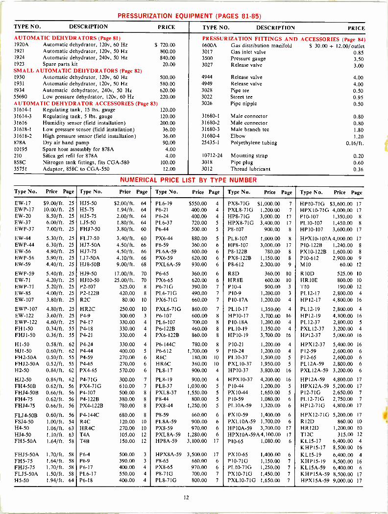
PRESSURIZATION EQUIPMENT (PAGES 81-85)
TYPE NO. DESCRIPTION PRICE TYPE NO. DESCRIPTION PRICE
AUTOMATIC DEHYDRATORS (Page 81) PRESSURIZATION FITTINGS AND ACCESSORIES (Page 84) 1920A Automatic dehydrator, 120v, 60 Hz $ 720.00 6600A Gas distribution manifold $ 30.00 + 12.00/outlet 1921 Automatic dehydrator, 120v, 50 Hz 800.00 3017 Gas inlet valve 0.85 1924 Automatic dehydrator, 240v, 50 Hz 840.00 3500 Pressure gauge 3.50 1923 Spare parts kit 20.00 3027 Release valve 3.00 SMALL AUTOMATIC DEHYDRATORS (Page 82) 1930 Automatic dehydrator, 120v, 60 Hz 500.00 4944 Release valve 4.00 1931 Automatic dehydrator, 120v, 50 Hz 580.00 4949 Release valve 4.00 1934 Automatic dehydrator, 240v, 50 Hz 620.00 3028 Pipe tee 0.50 55690 Low pressure dehydrator, 120v, 60 Hz 220.00 3022 Street tee 0.95 AUTOMATIC DEHYDRATOR ACCESSORIES (Page 83) 3026 Pipe nipple 0.50 31614-1 Regulating tank, 15 lbs. gauge 120.00 31614-3 Regulating tank, 5 lbs. gauge 120.00 31680-I Male connector 0.80 31616 Humidity sensor (field installation) 200.00 31680-2 Male connector 0.80 31618-1 Low pressure sensor (field installation) 36.00 31680-3 Male branch tee 1.80 31618-2 High pressure sensor (field installation) 36.00 31680-4 Elbow 1.20 878A Dry air hand pump 90.00 25435-1 Polyethylene tubing 0.16/ft. 10195 Spare hose assembly for 878A 4.00 210 Silica gel refil for 878A 4.00 10712-24 Mounting strap 0.20 858C Nitrogen tank fittings, fits CGA-580 100.00 3018 Pipe plug 0.60 35751 Adaptor, 858C to CGA-550 12.00 3012 Thread lubricant 0.36
NUMERICAL PRICE LIST BY TYPE NUMBER
Type No. Price Page Type No. Price Page Type No. Price Page Type No. Price Page Type No. Price Page
EW-17 $9.00/ft. 25 HJ5-50 $2.00/ft. 64 PL6-19 $550.00 4 PX8-71G $1,000.00 7 HP10-71G $3,600.00 17 EWP-17 10.00/ft. 25 H5-75 1.94/ft. 64 P6-21 400.00 4 PXL8-71G 1,200.00 7 HPX10-7IG 4,000.00 17 EW-20 8.50/ft. 25 HJ5-75 2.00/ft. 64 P6-24 400.00 4 HP8-71G 3,000.00 17 P10-107 1,350.00 8
EW-37 6.00/ft. 25 115-50 1.80/ft. 64 PL6-37 720.00 5 HPX8-71G 3,400.00 17 PL10-107 1,450.00 8
EWP-37 7.00/ft. 25 FHJ7-50 3.80/ft. 60 P6-44 500.00 5 P8-107 900.00 8 HPIO-107 3,600.00 17
EW-44 5.30/ft. 25 FLJ7-50 3.40/ft. 60 PX6-44 880.00 5 PL8-107 1,000.00 8 HPX1O-107A4,000.00 17
EWP-44 6.30/ft. 25 HJ7-50A 4.50/ft. 66 P6-59 360.00 6 HP8-107 3,000.00 17 P10 -122B 1,240.00 8
EW-56 4.90/ft. 25 HJ7-75 4.50/ft. 66 PL6A-59 600.00 6 P8 -122B 780.00 8 PX10-122B 1,600.00 8
EWP-56 5.90/ft. 25 LJ7-50A 4.10/ft. 66 PX6-59 620.00 6 PX8-122B 1,150.00 8 P10-612 2,900.00 9
EW-59 4.40/ft. 25 HJ8-50B 9.00/ft. 68 PXL6A-59 930.00 6 P8-612 2,300.00 9 MIO 60.00 12
EWP-59 5.40/ft. 25 HJ9-50 17.00/ft. 70 P6-65 360.00 6 R8D 360.00 10 RIOD 525.00 10
EW-71 4.20/ft. 25 HJ10-50 25.00/ft. 70 PX6-65 620.00 6 HR8E 600.00 10 HR10E 800.00 10
EWP-71 5.20/ft. 25 P2-107 525.00 8 P6 -71G 390.00 7 P10-4 900.00 3 T10 190.00 12
EW-85 4.00/ft. 25 P2 -122B 420.00 8 PL6-71G 490.00 7 P10-9 1,200.00 3 PL12-17 2,800.00 4
EW-107 3.80/ft. 25 R2C 80.00 10 PX6-71G 660.00 7 P10 -17A 1,200.00 4 HP12-17 4,800.00 16
EWP-107 4.80/ft. 25 HR2C 250.00 10 PXL6-71G 860.00 7 PL10-17 1,350.00 4 PL12-19 2,800.00 4
EW-122 3.60/ft. 25 P4-9 300.00 3 P6-107 600.00 8 HP10-17 3,700.00 16 HP12-19 4,800.00 16
EWP-122 4.60/ft. 25 P4-17 330.00 4 PL6-107 700.00 8 P10 -18A 1,200.00 4 PL12-37 2,800.00 5
FHI-50 0.34/ft. 55 P4-18 330.00 4 P6 -122B 460.00 8 PL10-19 1,350.00 4 PXLI2-37 3,200.00 4 FHJI-50 0.36/ft. 55 P4-21 330.00 4 PX6-122B 860.00 8 HP10-19 3,700.00 16 HP12-37 5,000.00 16
H1-50 0.58/ft. 62 P4-24 330.00 4 P6 -144C 780.00 8 P10-21 1,200.00 4 HPX12-37 5,400.00 16
HJI-50 0.60/ft. 62 P4-44 400.00 5 P6-612 1,700.00 9 P10-24 1,200.00 4 P12-59 2,600.00 6 FH2-50A 0.50/ft. 55 P4-59 270.00 6 R6C 180.00 10 PL10-37 1,500.00 5 P12-65 2,600.00 6
FHJ2-50A 0.52/ft. 55 P4-65 270.00 6 HR6C 360.00 10 PXL10-37 1,950.00 5 PL12A-59 2,800.00 6
H2-50 0.84/ft. 62 PX4-65 570.00 6 PL8-17 900.00 4 HP10-37 3,800.00 16 PXL12A-59 3,200.00 6
HJ2-50 0.86/ft. 62 P4 -71G 300.00 7 PL8-19 900.00 4 HPX10-37 4,200.00 16 HP12A-59 4,800.00 17
FH4-50B 0.62/ft. 56 PX4-71G 610.00 7 PL8-37 1,030.00 5 P10-44 1,200.00 5 HPXl2A-59 5,200.00 17
FHJ4-50B 0.66/ft. 56 P4-107 500.00 8 PXL8-37 1,550.00 5 PX10-44 1,650.00 5 P12 -71G 2,650.00 7
FH4-75 0.62/ft. 56 P4 -122B 380.00 8 P8-44 800.00 5 P10-59 1,080.00 6 PL12-71G 2,750.00 7
FHJ4-75 0.66/ft. 56 PX4-122B 780.00 8 PX8-44 1,250.00 5 PLl0A-59 1,320.00 6 HP12-71G 4,800.00 17
FLJ4-50B 0.60/ft. 56 P4 -144C 680.00 8 P8-59 660.00 6 PX10-59 1,400.00 6 HPX12-71G 5,200.00 17
FSJ4-50 1.00/ft. 54 R4C 120.00 10 PL8A-59 900.00 6 PXL10A-59 1,700.00 6 Rl2D 860.00 10
H4-50 1.06/ft. 63 HR4C 270.00 10 PX8-59 970.00 6 HP10A-59 3,700.00 17 HRI2D 1,200.00 10
HJ4-50 1.10/ft. 63 T4A 105.00 12 PXL8A-59 1,280.00 6 HPX10A-59A4,100.00 17 TI2C 315.00 12
FH5-50A 1.64/ft. 58 T4B 150.00 12 HP8A-59 3,100.00 17 P10-65 1,080.00 6 KL15-17 6,400.00 4
KHP15-17 8,500.00 16
FHJ5-50A 1.70/ft. 58 P6-4 500.00 3 HPX8A-59 3,500.00 17 PX10-65 1,400.00 6 KL15-19 6,400.00 4 FH5-75 1.64/ft. 58 P6-9 390.00 3 P8-65 660.00 6 P10 -71G 1,150.00 7 KHPI5-19 8,500.00 16
FHJ5-75 1.70/ft. 58 P6-17 400.00 4 PX8-65 970.00 6 PL 10-71G 1,250.00 7 KL15A-59 6,400.00 6 FLJ5-50A 1.50/ft. 58 PL6-17 550.00 4 P8 -71G 700.00 7 PX10-71G 1,450.00 7 KHP15A-59 8,500.00 17
H5-50 1.94/ft. 64 P6-18 400.00 4 PL8-71G 800.00 7 PXL10-71G 1,650.00 7 HPX15A-59 9,000.00 17
12
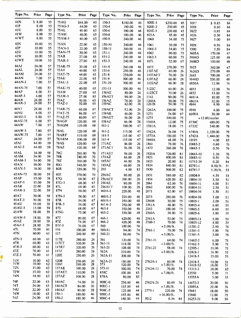
Type No. Price Page Type No. Price Page Type No. Price Page Type No. Price Page Type No. Price Page
41N $ 8.00 55 75AG $44.00 65 150-3 $180.00 46 920E-1 $230.00 45 3017 $ 0.85 84 41P 8.00 55 75AG-3 44.00 65 150-4 180.00 46 920E-2 230.00 45 3018 0.60 84 41U 8.00 55 75AL 40.00 65 150-6 190.00 46 920E-3 230.00 45 3022 0.95 84 41 W 8.00 55 75AM 40.00 65 150-8 190.00 46 925A 95.00 45 3026 0.50 84 4I WT 8.00 55 75AM-3 40.00 65 150-9 240.00 46 1060 34.00 75 3027 3.00 84
42N 10.00 55 75AN 22.00 65 150-10 240.00 46 1061 50.00 75 3028 0.50 84 42P 10.00 55 75AN-3 22.00 65 150-11 240.00 46 1061-3 34.00 75 3500 3.50 84 42U 10.00 55 75AN-75 30.00 65 151-1 240.00 46 1062 90.00 75 3605A 170.00 47 42W 10.00 55 75AR 27.00 65 151-2 240.00 46 1062-3 60.00 75 3606D 125.00 49 42WT 10.00 55 75AR-3 27.00 65 151-3 240.00 46 1071 52.00 67 3608D 150.00 49 44AJ 24.00 57 75AR-75 30.00 65 151-4 240.00 46 1073 270.00 75 3625 360.00 47 44AL 24.00 57 75AT 44.00 65 151-6 250.00 46 1107AE 60.00 26 3626D 270.00 49 44AM 24.00 57 75AT-75 44.00 65 151-8 250.00 46 1107AET 70.00 26 3645 700.00 47 44AN 7.00 57 75AU 22.00 65 151-9 300.00 46 1107AZ 66.00 28 3646D 530.00 49 44AN-3 7.00 57 75AU-3 22.00 65 151-10 300.00 46 1 122AZ 66.00 28 4850A 12.00 76
44AN-75 7.00 57 75AU-75 40.00 65 151-11 300.00 46 1122C 60.00 26 4851 12.00 76 44AP 6.00 57 75AW 27.00 65 156AE 80.00 26 1122CT 70.00 26 4852 13.00 76 44AP-3 6.00 57 75AW-3 27.00 65 156AET 90.00 26 1162 90.00 75 4861A 10.00 75 44AR 24.00 57 75AZ 30.00 65 156AZ 78.00 28 1260A 30.00 75 4862A 32.00 75 44AR-3 24.00 57 75AZ-3 30.00 65 159AC 42.00 26 1261B 54.00 75 4944 4.00 84
44AT 24.00 57 77AR-75 60.00 67 159ACT 52.00 26 1262A 100.00 75 4949 4.00 84 44AU 6.00 57 77AT-75 86.00 67 159AE 46.00 26 1271 54.00 67 6600A 30.00 84 44AU-3 6.00 57 77AZ-75 80.00 67 159AET 56.00 26 1273 340.00 75 + 12.00/outlet 44AU-75 6.00 57 78AGF 120.00 69 159AZ 66.00 28 1560A 12.00 75 6730C 480.00 78 44AW 7.00 57 78AGM 110.00 69 161-1 100.00 47 1561A 18.00 75 6732C 540.00 78
44AW-3 7.00 57 78AL 120.00 69 161-2 115.00 47 1562A 36.00 75 6740A 1,320.00 79 44AW-75 7.00 57 78ARF 110.00 69 161-3 115.00 47 1573A 100.00 75 6742A 1,440.00 79 44AZ 24.00 57 78ARM 100.00 69 161-4 115.00 47 1860A 48.00 76 10195 4.00 83 45AJ 44.00 59 78AS 120.00 69 I71AC 46.00 26 1861 70.00 76 10683-2 0.60 76 45AJ-3 44.00 59 78AZ 120.00 69 17IACT 56.00 26 1872 360.00 76 10683-3 0.50 76
45AL 34.00 59 79G 260.00 70 171AET 56.00 26 1920A 720.00 81 10683-10 1.30 76 45AM 34.00 59 79R 240.00 70 171AZ 66.00 28 1921 800.00 81 10683-11 0.50 76 45AM-3 34.00 59 79Z 260.00 70 185AC 46.00 26 1923 20.00 81 10712-24 0.20 84 45AN 18.00 59 80G 340.00 70 I85AZ 66.00 28 1924 840.00 81 10791-1 0.30/ft. 51 45AN-3 18.00 59 80R 320.00 70 210 4.00 83 1930 500.00 82 10791-7 1.20/ft. 51
45AN-75 18.00 59 80Z 370.00 70 256AC 90.00 26 1931 580.00 82 10804-9 4.50 51 45AP 15.00 59 87G 68.00 67 256ACT 100.00 26 1934 620.00 82 10804-10 5.50 51 45AP-3 15.00 59 87G-3 68.00 67 256AE 90.00 26 2061 62.00 76 10804-11 4.00 51 45AR 22.00 59 87L 68.00 67 256AET 100.00 26 2062 100.00 76 10804-31 2.50 51 45AR-3 22.00 59 87N 58.00 67 460A-1 220.00 48 2071 62.00 67 10804-34 3.50 51
45AT 30.00 59 87N-3 58.00 67 460A-2 220.00 48 2073 280.00 76 10804-36 3.00 51 45AT-3 30.00 59 87R 54.00 67 461A-1 250.00 48 2260B 30.00 75 10805-1 2.00 51 45AU 15.00 59 87R-3 54.00 67 461A-2 250.00 48 2261A 48.00 75 10805-4 6.00 51 45AU-3 15.00 59 87S 68.00 67 465-1 350.00 48 2262 100.00 75 10805-5 6.00 51 45AW 18.00 59 87SG 75.00 67 465-2 350.00 48 2360A 38.00 75 10805-6 3.00 51
45AW-3 18.00 59 87T 80.00 67 466-1 420.00 48 2361A 52.00 75 10805-11 5.00 51 45AZ 28.00 59 87Z 76.00 67 466-2 420.00 48 2760-1 70.00 74 10805-12 4.00 51 45AZ-3 28.00 59 87Z-3 76.00 67 560 100.00 74 +2.00/ft. 11381-2 2.50 76 47L 70.00 61 116 100.00 49 560-11 94.00 74 2761-1 70.00 74 11381-3 3.00 76 47N 60.00 61 117 240.00 49 560-21 88.00 74 +3.00/ft. 11381-5 3.00 76
47N-3 60.00 61 117E 280.00 26 561 120.00 74 2761-1I 64.00 74 11662-2 6.00 71 47R 60.00 61 II7ET 320.00 26 561-11 114.00 74 +3.00/ft. 11662-3 5.00 71 47R-3 60.00 61 117RT 320.00 26 561-21 108.00 74 2761-21 58.00 74 12395-1 15.00 71 47Z 70.00 61 117Z 280.00 28 562A 210.00 74 +3.00/ft. 12418-I 16.00 51 47Z-3 70.00 61 120E 250.00 26 562A-11 200.00 74 12418-3 15.00 51
7IN 10.00 62 120R 250.00 26 562A-21 190.00 75 2762A-1 80.00 74 12418-5 10.00 51 71W 10.00 62 120Z 260.00 28 573 520.00 74 +7.00/ft. 12418-12 16.00 51 72N 15.00 62 137AE 100.00 26 573 -II 500.00 74 2762A-11 70.00 74 13212-2 10.00 62 72W 15.00 62 137AET 110.00 26 858C 100.00 83 +7.00/ft. 13550 5.00 71 74N 18.00 63 I37AZ 100.00 28 878A 90.00 83 13555A 5.00 33
74P 22.00 63 144AC 74.00 26 900C-0 230.00 44 2762A-21 60.00 74 14672-3 20.00 50 74T 24.00 63 I44ACT 84.00 26 900C -I 135.00 44 +7.00/ft. 15093A 22.00 76 74U 22.00 63 144AZ 90.00 28 900C-2 125.00 44 2773-I 220.00 74 15681 18.00 50 74W 18.00 63 150-1 180.00 46 900C-3 145.00 44 +16.00/ft. 15840 12.00 75 74Z 24.00 63 150-2 180.00 46 900C-4 140.00 44 3012 0.36 84 16253-21 9.00 50
13
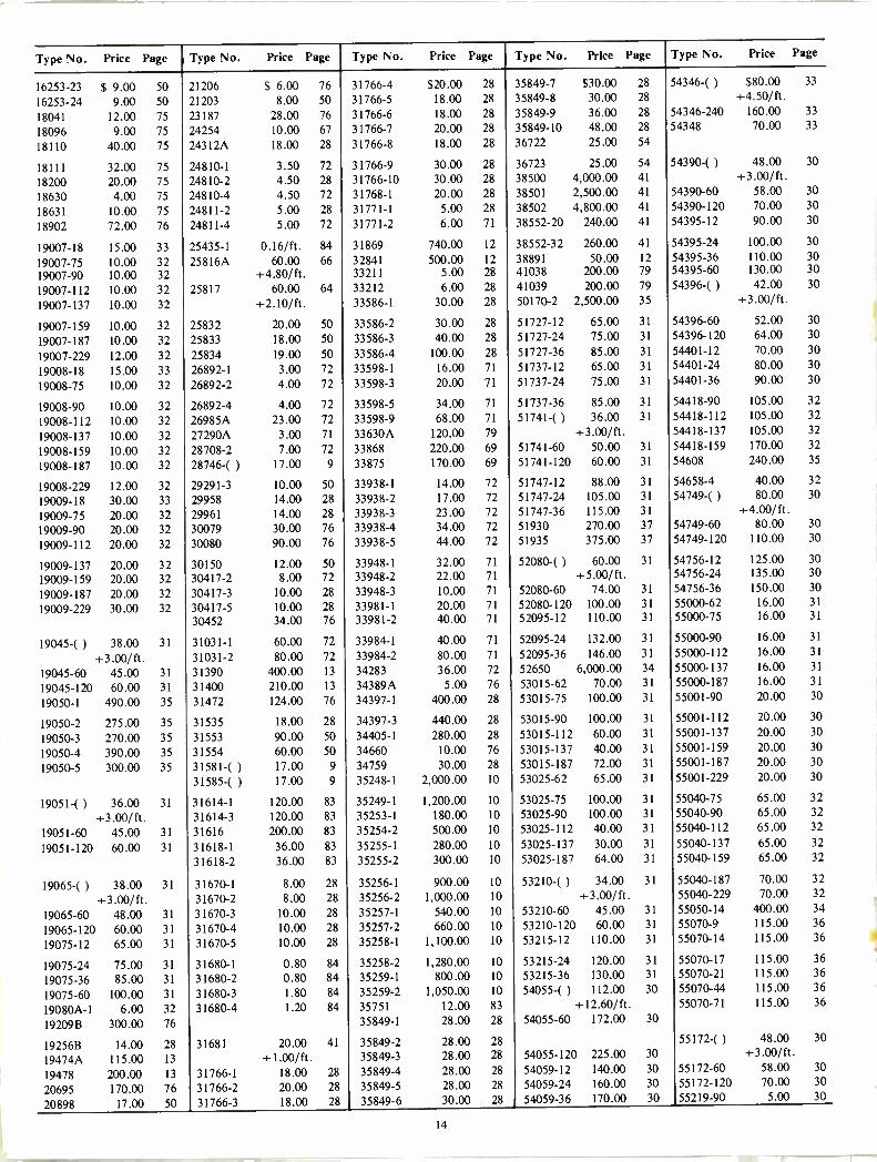
Type No. Price Page Type No. Price Page Type No. Price Page Type No. Price Page Type No. Price Page
16253-23 $ 9.00 50 21206 $ 6.00 76 31766-4 $20.00 28 35849-7 $30.00 28 54346-( ) $80.00 33
16253-24 9.00 50 21203 8.00 50 31766-5 18.00 28 35849-8 30.00 28 +4.50/ft.
18041 12.00 75 23187 28.00 76 31766-6 18.00 28 35849-9 36.00 28 54346-240 160.00 33
18096 9.00 75 24254 10.00 67 31766-7 20.00 28 35849-10 48.00 28 54348 70.00 33
18110 40.00 75 24312A 18.00 28 31766-8 18.00 28 36722 25.00 54
18111 32.00 75 24810-1 3.50 72 31766-9 30.00 28 36723 25.00 54 54390-( ) 48.00 30
18200 20.00 75 24810-2 4.50 28 31766-10 30.00 28 38500 4,000.00 41 +3.00/ft.
18630 4.00 75 24810-4 4.50 72 31768-1 20.00 28 38501 2,500.00 41 54390-60 58.00 30
18631 10.00 75 24811-2 5.00 28 31771-1 5.00 28 38502 4,800.00 41 54390-120 70.00 30
18902 72.00 76 24811-4 5.00 72 31771-2 6.00 71 38552-20 240.00 41 54395-12 90.00 30
19007-18 15.00 33 25435-1 0.16/ft. 84 31869 740.00 12 38552-32 260.00 41 54395-24 100.00 30
19007-75 10.00 32 25816A 60.00 66 32841 500.00 12 38891 50.00 12 54395-36 110.00 30
19007-90 10.00 32 + 4.80/ft. 33211 5.00 28 41038 200.00 79 54395-60 130.00 30
19007-112 10.00 32 25817 60.00 64 33212 6.00 28 41039 200.00 79 54396-( ) 42.00 30
19007-137 10.00 32 +2.10/ft. 33586-1 30.00 28 50170-2 2,500.00 35 +3.00/ft.
19007-159 10.00 32 25832 20.00 50 33586-2 30.00 28 51727-12 65.00 31 54396-60 52.00 30
19007-187 10.00 32 25833 18.00 50 33586-3 40.00 28 51727-24 75.00 31 54396-120 64.00 30
19007-229 12.00 32 25834 19.00 50 33586-4 100.00 28 51727-36 85.00 31 54401-12 70.00 30
19008-18 15.00 33 26892-1 3.00 72 33598-1 16.00 71 51737-12 65.00 31 54401-24 80.00 30
19008-75 10.00 32 26892-2 4.00 72 33598-3 20.00 71 51737-24 75.00 31 54401-36 90.00 30
19008-90 10.00 32 26892-4 4.00 72 33598-5 34.00 71 51737-36 85.00 31 54418-90 105.00 32
19008-112 10.00 32 26985A 23.00 72 33598-9 68.00 71 51741-( ) 36.00 31 54418-112 105.00 32
19008-137 10.00 32 27290A 3.00 71 33630A 120.00 79 +3.00/ft. 54418-137 105.00 32
19008-159 10.00 32 28708-2 7.00 72 33868 220.00 69 51741-60 50.00 31 54418-159 170.00 32
19008-187 10.00 32 28746-( ) 17.00 9 33875 170.00 69 51741-120 60.00 31 54608 240.00 35
19008-229 12.00 32 29291-3 10.00 50 33938-1 14.00 72 51747-12 88.00 31 54658-4 40.00 32
19009-18 30.00 33 29958 14.00 28 33938-2 17.00 72 51747-24 105.00 31 54749-( ) 80.00 30
19009-75 20.00 32 29961 14.00 28 33938-3 23.00 72 51747-36 115.00 31 +4.00/ft.
19009-90 20.00 32 30079 30.00 76 33938-4 34.00 72 51930 270.00 37 54749-60 80.00 30
19009-112 20.00 32 30080 90.00 76 33938-5 44.00 72 51935 375.00 37 54749-120 110.00 30
19009-137 20.00 32 30150 12.00 50 33948-1 32.00 71 52080-( ) 60.00 31 54756-12 125.00 30
19009-159 20.00 32 30417-2 8.00 72 33948-2 22.00 71 +5.00/ft. 54756-24 135.00 30
19009-187 20.00 32 30417-3 10.00 28 33948-3 10.00 71 52080-60 74.00 31 54756-36 150.00 30
19009-229 30.00 32 30417-5 10.00 28 33981-1 20.00 71 52080-120 100.00 31 55000-62 16.00 31
30452 34.00 76 33981-2 40.00 71 52095-12 110.00 31 55000-75 16.00 31
19045-( ) 38.00 31 31031-1 60.00 72 33984-1 40.00 71 52095-24 132.00 31 55000-90 16.00 31
+3.00/ft. 31031-2 80.00 72 33984-2 80.00 71 52095-36 146.00 31 55000-112 16.00 31
19045-60 45.00 31 31390 400.00 13 34283 36.00 72 52650 6,000.00 34 55000-137 16.00 31
19045-120 60.00 31 31400 210.00 13 34389A 5.00 76 53015-62 70.00 31 55000-187 16.00 31
19050-1 490.00 35 31472 124.00 76 34397-1 400.00 28 53015-75 100.00 31 55001-90 20.00 30
19050-2 275.00 35 31535 18.00 28 34397-3 440.00 28 53015-90 100.00 31 55001-112 20.00 30
19050-3 270.00 35 31553 90.00 50 34405-1 280.00 28 53015-112 60.00 31 55001-137 20.00 30
19050-4 390.00 35 31554 60.00 50 34660 10.00 76 53015-137 40.00 31 55001-159 20.00 30
19050-5 300.00 35 31581-( ) 17.00 9 34759 30.00 28 53015-187 72.00 31 55001-187 20.00 30
31585-( ) 17.00 9 35248-1 2,000.00 10 53025-62 65.00 31 55001-229 20.00 30
19051-() 36.00 31 31614-1 120.00 83 35249-1 1,200.00 10 53025-75 100.00 31 55040-75 65.00 32
+3.00/ft. 31614-3 120.00 83 35253-1 180.00 10 53025-90 100.00 31 55040-90 65.00 32
19051-60 45.00 31 31616 200.00 83 35254-2 500.00 10 53025-112 40.00 31 55040-112 65.00 32
19051-120 60.00 31 31618-1 36.00 83 35255-1 280.00 10 53025-137 30.00 31 55040-137 65.00 32
31618-2 36.00 83 35255-2 300.00 10 53025-187 64.00 31 55040-159 65.00 32
19065-( ) 38.00 31 31670-1 8.00 28 35256-1 900.00 10 53210-( ) 34.00 31 55040-187 70.00 32
+3.00/ft. 31670-2 8.00 28 35256-2 1,000.00 10 +3.00/ft. 55040-229 70.00 32
19065-60 48.00 31 31670-3 10.00 28 35257-1 540.00 10 53210-60 45.00 31 55050-14 400.00 34
19065-120 60.00 31 31670-4 10.00 28 35257-2 660.00 10 53210-120 60.00 31 55070-9 115.00 36
19075-12 65.00 31 31670-5 10.00 28 35258-1 1,100.00 10 53215-12 110.00 31 55070-14 115.00 36
19075-24 75.00 31 31680-1 0.80 84 35258-2 1,280.00 10 53215-24 120.00 31 55070-17 115.00 36
19075-36 85.00 31 31680-2 0.80 84 35259-1 800.00 10 53215-36 130.00 31 55070-21 115.00 36
19075-60 100.00 31 31680-3 1.80 84 35259-2 1,050.00 10 54055-( ) 112.00 30 55070-44 115.00 36
19080A-1 6.00 32 31680-4 1.20 84 35751 12.00 83 +12.60/ft. 55070-71 115.00 36
19209B 300.00 76 35849-1 28.00 28 54055-60 172.00 30
19256B 14.00 28 31681 20.00 41 35849-2 28.00 28 55172-( ) 48.00 30
19474A 115.00 13 +1.00/ft. 35849-3 28.00 28 54055-120 225.00 30 +3.00/ft.
19478 200.00 13 31766-1 18.00 28 35849-4 28.00 28 54059-12 140.00 30 55172-60 58.00 30
20695 170.00 76 31766-2 20.00 28 35849-5 28.00 28 54059-24 160.00 30 55172-120 70.00 30
20898 17.00 50 31766-3 18.00 28 35849-6 30.00 28 54059-36 170.00 30 55219-90 5.00 30
14

Type No. Price Page Type No. Price Page Type No. Price Page Type No. Price Page Type No. Price Page
55219-112 $ 5.00 30 55224-112 $ 2.00 31 55234-60 $100.00 30 56045-112 $40.00 30 60008-4 $2,650.00 36 55219-137 5.00 30 55224-137 2.00 31 55234-120 130.00 30 56045-137 40.00 30 60008-14 2,000.00 36 55219-159 5.00 30 55224-187 3.00 31 55235-12 140.00 30 56045-159 50.00 30 60010-4 3,700.00 36 55219-187 5.00 30 55229-90 56.00 30 55235-24 160.00 30 56045-187 65.00 30 60102-1 800.00 35 55219-229 6.00 30 55229-112 58.00 30 55235-36 170.00 30 56045-229 65.00 30 60102-3 900.00 35
55220-62 42.00 31 55229-137 60.00 30 55244 2,500.00 34 56090 1,125.00 37 60102-5 1,100.00 35 55220-75 42.00 31 55229-159 75.00 30 55249-4 40.00 32 56207 20.00 33 60103-1 1,300.00 35 55220-90 46.00 31 55229-187 90.00 30 55305-1 200.00 35 56520-20 145.00 36 60103-3 1,400.00 35 55220-112 48.00 31 55229-229 155.00 30 55305-3 300.00 35 56520-40 145.00 36 60103.5 1,600.00 35 55220-137 50.00 31 55230-90 56.00 30 55305-5 500.00 35 56520-70 145.00 36 60104-1 840.00 35
55220-187 70.00 31 55230-112 58.00 30 55353 2,500.00 34 57001-107 420.00 33 60104-3 940.00 35 55221-62 42.00 31 55230-137 60.00 30 55520-10 400.00 35 57001-127 420.00 33 60104-5 1,140.00 35 55221-75 42.00 31 55230-159 75.00 30 55674-90 40.00 30 57222-107 280.00 33 60109-1 450.00 35 55221-90 46.00 31 55230-187 90.00 30 55674-112 40.00 30 57222-127 280.00 33 60109-3 550.00 35 55221-112 48.00 31 55230-229 155.00 30 55674-137 40.00 30 59135 1,150.00 37 60109-5 750.00 35
55221-137 50.00 31 55231-90 85.00 30 55674-159 40.00 30 59210-90 100.00 32 60111-1 340.00 35 55221-187 70.00 31 55231-112 70.00 30 55674-187 50.00 30 59210-112 100.00 32 60111-3 440.00 35 55222-62 45.00 31 55231-137 60.00 30 55674-229 50.00 30 59210-137 100.00 32 60111-5 640.00 35 55222-75 64.00 31 55231-159 90.00 30 55675-62 40.00 31 59220-5 50.00 32 60115-I 250.00 35 55222-90 75.00 31 55231-187 92.00 30 55675-75 40.00 31 59220-6 90.00 32 60115-3 350.00 35
59220-13 40.00 32 60115-5 550.00 35 55222-112 60.00 31 55231-229 160.00 30 55675-90 40.00 31 59220-37 60.00 32 60116-1 250.00 35 55222-137 50.00 31 55233-12 90.00 30 55675-112 50.00 31 60003-14 900.00 36 60116-3 350.00 35 55222-187 72.00 31 55233-24 100.00 30 55675-137 64.00 31 60003-21 840.00 36 60116-5 550.00 35 55224-62 3.00 31 55233-36 110.00 30 55675-187 64.00 31 60004-14 1,200.00 36 70749 2,000.00 4 55224-75 3.00 31 55234-( ) 90.00 30 55690 220.00 82 60004-21 1,100.00 36 70750 3,200.00 4 55224-90 3.00 31 +5.00/ft. 56045-90 40.00 30 60006-21 1,300.00 36 70751 6,400.00 4
SHIPPING REEL INFORMATION Very short lengths of HELIAX elliptical waveguide and HELIAX coaxial cable are usually shipped in cardboard cartons or in open wooden crates as shown in Catalog 26. Most shipments of HELIAX elliptical waveguide and HELIAX coaxial cable up to 3" in size are made on non -deposit, disposable wooden reels. Cable of 3" or larger sizes and very long continuous lengths of smaller sizes are shipped on returnable reels requiring a reel deposit. Cables cut to length and terminated at the factory will be shipped with a length tolerance of plus 2%, minus 0%. Cable may be supplied with a closer mechanical length tolerance on special order for a nominal additional charge.
REEL SIZE
TYPE NO.
OUTSIDE DIAMETER WIDTH
TARE WT., LBS. DEPOSIT
4 Ft. - 48 in. 24 in. 94 N/C 6 Ft. - 72 in. 31 in. 315 N/C 6 Ft. 25190-3 74 in. 46 in. 925 $ 150.00 7 Ft. 25190-2 86 in. 52 in. 1645 250.00 7-1/2 Ft. 25190-4 93 in. 40 in. 1900 300.00 8 Ft. 25190-5 98 in. 66 in. 2100 350.00 9 Ft. 25190-6 110 in. 70 in. 2800 400.00 10-1/2 Ft. 25190-9 128 in. 80 in. 3600 600.00 12 Ft. 29076 146 in. 84 in. 4500 1,200.00 12-1/2 Ft. 38269-2 154 in. 120 in. 6500 2,000.00 14 Ft. 38269-1 172 in. 120 in. 7000 2,600.00
Notes: 1) Tare/Wt. is the empty weight of the reel plus an outside covering (agging) for shipment. For shipping weight, add weight of cable
shown in catalog. (2) Dimensions and weights are nominal, for planning purposes and are not guaranteed. (3) Reel types 29076, 38269-2 and 38269-1 are steel, all others are of wood construction. (4) Reel types 38269-2 and 38269-1 can be dis -assembled to reduce return shipping costs. (5) Reels shown are for domestic shipment only. Special reels for export shipments or other special applications are available on request.
RETURNABLE REEL POLICY Reel deposits are not included in the price of the cable but are charged seperately, charges being on a net basis (no discount allowed). Full credit will be allowed for reels returned within twelve months from date of shipment, in good condition, reasonable wear and tear accepted. Reels shall be returned at customer's expense, F.O.B. the Andrew plant, 10500 W. 153rd. Street, Orland Park, Illinois 60462. Shipping charges for return of reels should be prepaid. If reels are returned Collect, we will deduct shipping costs from reel deposit. Reels requiring repairs will be accepted at our option, and reasonable charge for repairs will be deducted from the deposit. There is no charge for lagging and therefore no credit will be allowed for return of lagging. No deposit is charged and therefore no credit will be allowed for return of Non -Returnable Reels.
15
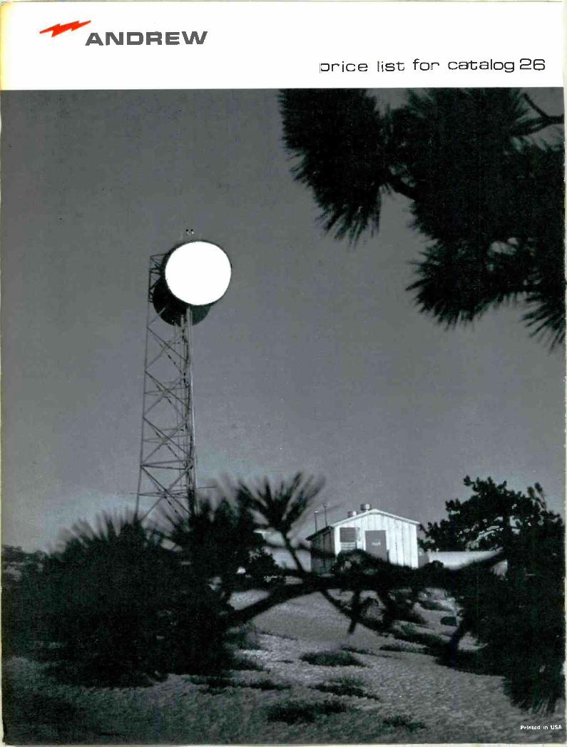
ANDREW price list for catalog 26
Printed in USA
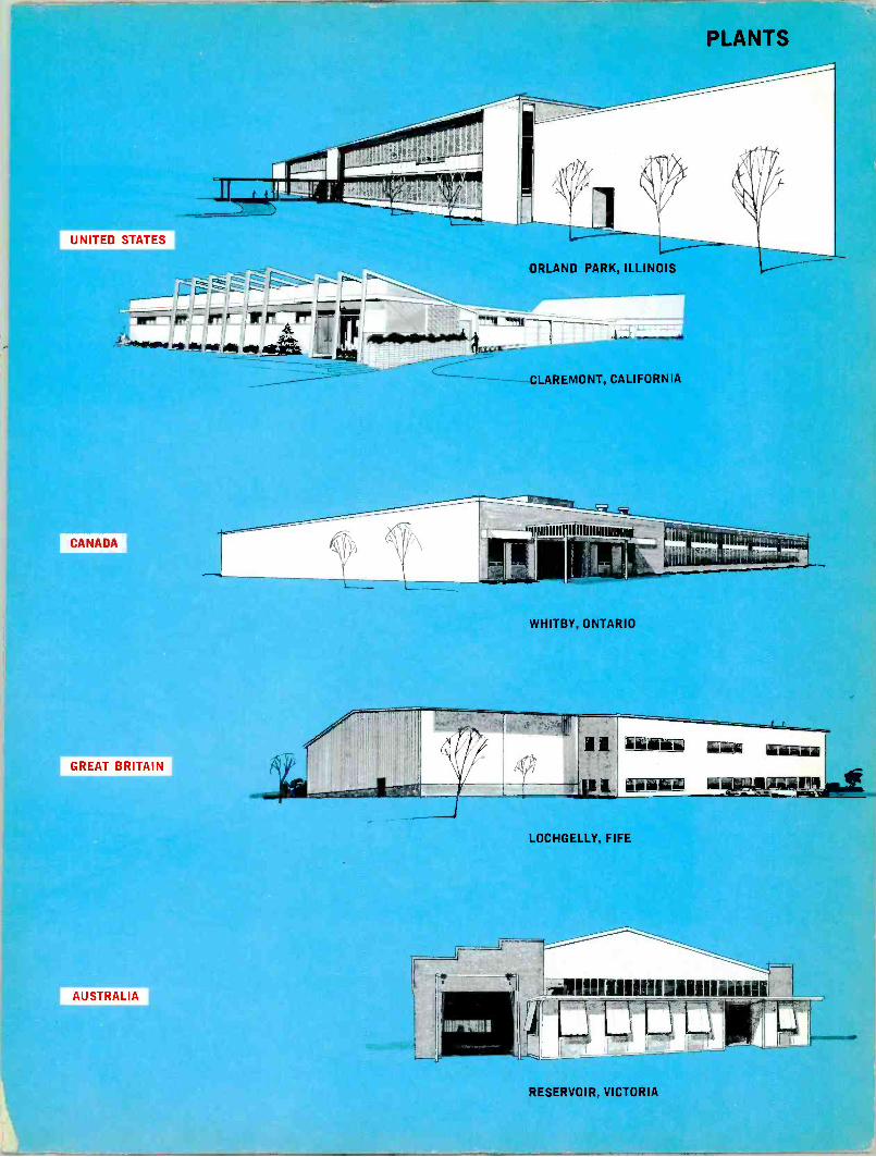
UNITED STATES
-111rr-1
4.4_4211_ 446.0.4.Nomi
CANADA
GREAT BRITAIN
AUSTRALIA
ORLAND PARK, ILLINOIS
CLAREMONT, CALIFORNIA
WHITBY, ONTARIO
IC
jut ii l&einku w Äkiiiüi
I Ii' 6--eypiitary
LOCHGELLY, FIFE
Irel01111111111111111111iifill
RESERVOIR, VICTORIA
ANDREW catalog 26 antennas/transmission lines
Printed in U.S.A.