android research and development program u) air i …
TRANSCRIPT

AD-A 127 359 AN ANDROID RESEARCH AND DEVELOPMENT PROGRAM U) AIR IENIERN ALRMR8 E 3FORCE INST OF TECH WRIGHT-PATTERSON AFB OH SCHOOL OF
UNCLASSIFIED F/G 15/5
B.I
I1.25 111 4 3 6
MICROCOPY RESOLUliON TEST CHART
NATIONAL BUREAU OF STAND4RSI%93-A

AN ANDROID RESEARCHAND
DEVELOPMENT PROGRAM
THESIS
F 'iT/GE/EE/83M-3 Roslyn J. TaylorCaptain USAF
_J
LDEPARTMENT OF THE AIR FORCE
C.2 AIR UNIVERSITY (ATC)
AIR FORCE INSTITUTE OF TECHNOLOGYELECTE n
Wright-Patterson Air Force Base, Ohio S APR28 I3U
" a3 04 28 087 E

V AFIT/GE/EE/83M-3
AN AhjROID RESEARCHAND
DEVELOPMENT PROGRAM
THESIS
AFIT/GE/EE/83M-3 Roslyn J. Taylorcaptain USAF
Approved for public release; distribution unltmited
* IDTfc_________ ELECTE 9

AFIT/GE/EE/83M-3
AN ANDROID RESEARCH AND DEVELOPMENT PROGRAM
THESIS
Presented to the Faculty of the School of Engineering
of the Air Force Institute of Technology
Air University
in Partial Fulfillment of the
Requirements for the Degree of
Master of Science
Accession ForNTIS .RA&I
DTIC TABU nnno uned 0by Justification
Roslyn J. Taylor, B.S., B.S.E.E.Distribution/Captain USAFAvailability Codes
Graduate Electrical Engineer Di dai/or--Spel
January 1983
Approved for public release; distribution unlimited DTIC+.IELECT.
APR. 2 8 1983

Preface
This thesis is dedicated to the memory of my father,
Raymond Oliver Solander (26 November 1917 to 27 October
1982).
Robotics is a rapidly growing field. Interest has grown
worldwide as well as within the Department of Defense. This
project deals with an extension of robotics: a very
sophisticated mechanism termed, herein, an android.
(2ti
_ _ _ _ _ _ _

Acknowledgements
It is impossible to acknowledge everyone's help,
individually. Although, special thanks must go to my thesis
sponsor, Dr. Ints Kaleps of the Air Force Aerospace Medical
Research Laboratory. And, I must thank Dr. Jones, who
became my thesis advisor after my original advisor was
transferred. And, last but not least, Dr. Hartrum, I thank
you for acting as my assistant thesis advisor.
My deepest, most heartfelt thanks must go to my new
husband, Richard, and my new four-year old son, Andrew, for
their unfailing support during the past fifteen months.
Without their help, sanity retention would have been
impossible. And last, but certainly not least, I must thank
my mother, Ruth Solander, for coming to my rescue during her
own period of personal tragedy. When my husband was
transferred to Korea, and my babysitter moved with only two
weeks left to finish writing this thesis, mom arrived and
took over everything except (unfortunately) writing my
thesis. She proofread, pulled carbons, burst perforated
i pages, and collated all of my rough drafts after her arrival
(not to mention such mundane things as cooking, cleaning,
nursing, babysitting, etcl) Without her help and support,
this work could not have been finished. Thank you, all of
you, again.
(ii Roslyn J. Taylor
ii6

ContentsPage
Preface...................... ..
Acknowledgements................... . i
List of Figures ..................... vi
Abstract..........................vii
I. Introduction....................1
Background.....................1Problem and;cope...................5
Definitions .. .. .. .. .. .. ..... 5objectives...... .. .. .. .. .. ...... 7
Assumptions. ................... 1Approach...................11organization....................11
II. User Requirements .................... 13
Requirements Description ........... 13Basic Maintenance Tasks Summary. ........ 20
III. Android Requirements................23
Desired Capabilities..............23Current State of the Art ............ 33
IV. Areas Requiring Further Research .......... 46
Background .. .. .. .. .. .. .. .... 46Areas Requiring Further Research ........ 50
Common Steps................50IC2 .. ................... 50Perception..................52Manipulators................52Mobility .......... 53
What Can Air Force*Agencies Do?..........54AFIT . . . . .. .. .. .. .. .. ... 54AFAMRI ............... . 56Other Air Force Agencies ............ 57
V. Mobile Platform Project ............... 59
VI. Conclusions and Recommendations . . . . . . . . 67
Discussion . . . . . . . . . . . . . . . . 67Conclusio ns ... .. .. .... . . . 0. . 68Recomdain . t.. o... . . . . . . .. 69
____ __ ____ ___ ___iv

* Contents
Page
Further Recommendations for R2P2 . . . . . 70Description of a RoboticClearing House . .. .. .. .. .. . .. 72
Bibliography ..... ...... ... .. .. .. 76
Related Sources Bibliography (Annotated). ........ 82
Appendix A: Analysis Diagrams ..... ........ 92
Appendix B: Data Definitions .. ............ 116
Appendix C: Audio Cassette RecorderPrograms .. .. .............. 120
Appendix D: List of Contacts andSuggested Contacts .. ........... 131
Appendix E: DC Gearmotor Specifications. ....... 135
Vita......... .... ... .. ... .. .. 139
(1v

List of FiguresFigure Page
1 A-0, Maintain Aircraft. .............. 15
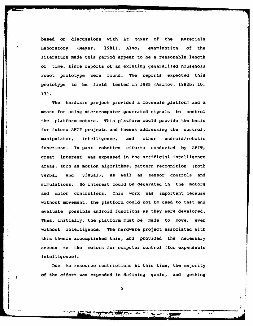
2 AO, Make Aircraft Flyable.............16
3 Motor Controller. ................. 63
4 Input Signal Controller .............. 64
5 Clearing House Relationships ............ 73
6 Information Exchange withinClearing House....................74
7 A-0, Maintain Aircraft. .............. 93
8 AO, Make Aircraft Flyable.............95
9 A2, Identify Aircraft ............... 97
10 A3, Accomplish Post-Flight Check .. ........ 98
11 A31, Direct Aircraft ................ 100
12 A32, Secure Aircraft ................ 102
13 A4, Accomplish Ground Maintenance ......... 106
14 A44, Determine Component Condition. ........ 108
15 A45, Fix Bad Component ............... 109
16 A5, Pre-Flight Check. ............ 1ll
17 A51, Accomplish Refuel/Rearm. ..... ....... 114
vi

AFIT/GE/EE/83M-3
Abstract
This report identifies areas requiring further research
to develop a detailed research and development plan for an
aircraft maintenance android. The general user requirements
are defined and the desired android capabilities are
addressed to meet the defined user requirements. The user
requirements are defined independently of aircraft type.
Structured analysis diagrams are used to describe the
functional requirements. Specific recommendations are made.
vii
-P

AN ANDROID RESEARCH AND DEVELOPMENT PROGRAM
I. Introduction
Background
Robots and androids bring varied images and definitions
to mind. Some of these images and definitions stem from
fictional literature associations, others from practical
involvement with industry. The history and definitions
presented in the background section of this introduction
provide a common basis of knowledge between the author and
the readers. The remaining sections of the introduction
provide a transition from these definitions and history into
the work accomplished by this thesis.
Joseph F. Engelberger, president and founder of
Unimation, Inc. (of Danbury, Connecticut, the first U.S.
robot manufacturer), claimed his interest in robots started
in the 1940s while an undergraduate physics-major at
Columbia University. He read the robot stories of his
fellow Columbian, Isaac Asimov (Asimov, 1982a: xiii). Many
of us can say the same thing--our interest in a particular
scientific area (robots for example) stemmed from reading
1

the fiction and speculations of others. It is easy, once
the imagination is captured, to expend energy and effort to
see if our dreams can be realized.
Asimov and robots are almos- always thought of together;
however, Isaac Asimov did not write the first robot story.
In 1942, he did invent the term 'robotics'. The robots he
envisioned were more like the 'industrial robots' of
today--manipulators "created by engineers to do specific
jobs and with safety features built in (Asimov, 1982a:
xiii)". The first story about a robot (although not called
a robot) was mentioned in legend--during the Middle Ages!
This was the Golem, brought to life by Rabbi Loew of Prague
in the Middle Ages. This robot was formed of clay (Asimov,
1982a: 57; Raphael, 1976: 253).
Karel Capek's play 'R.U.R.', introduced the term'robot' to the world in 1920. But it did notinvolve robots in the strictest sense of the word.The robots manufactured by Rossum's Universal Robots(the 'R.U.R.' of the title) were androids (Asimov,1982a: 153).
So much for the past of robots and robotics; but where
are they now?
Portia Isaacson predicts that we will soon seerobot stores in addition to our current computerstores and software stores.. .Jerome Hamlinconstructed a robot 'butler' at home. He named itComro I and persuaded Neiman-Marcus to feature therobot, priced at $15,000, in its [1981] Christmascatalog. The store sold three. Hamlin is nowworking on a robot kit that he plans to sell forunder $2000. Heath has already demonstrated aprototype robot kit that it plans to introduceeither later this year or next year for between$1500 and $3000. Several companies are alreadyselling computer controlled arms and bodies in kitform that range in price from $700 to $2500, andthere are rumors that some toy companies have
2
t. .,_._

developed prototypes of true robotic toys that willsell in the $300 to $500 price range. So far, thepersonal robotics products and projects that havebeen built are awkward and not very useful,reminiscent of the early personal computers. Butmore and more experimenters are getting involved inrobotics projects, and the likelihood is that wewill soon see the fruits of these labors translatedinto a mushrooming new market (Libes, 1982: 446,449).
With predictions of robot stores and promises of robot kits
both by individuals and companies, it appears that robots
have caught the imagination and the minds of laymen. But
currently, the people who have the largest demand for robots
are the industrialists.
Industry, however, has its own definition of a robot.
Jack Lohr, the vice-president of Robotics International,
provided an official industry definition:
A robot is a reprogrammable multifunctionalmanipulator designed to move material, parts, tools,or special devices, through variable programmedmotions for the performance of a variety of tasks(Seminar, 1982).
Industry first used industrial robots (built by Unimation,
Inc.) for die casting in the 1960s (Calahan, 1982: 130). So
far, industry is the largest robotics user, with the
automotive industry as the largest single user (Freedman,
1982). As such, research and development has been conducted
primarily to meet industry's needs. Since industry provided
the funding and impetus for the research, that is only
natural.
However, "the Pentagon is calling for a supportive role
fostering the U.S. development of robotics technology
(Military, 1982: 4)." With this increased Department of
3
I

Defense (DOD) interest in robotics, an evaluation of where,
how, and what impact robots will have on DOD is necessary.
A very brief overview of the DOD Research Program in
Robotics was published in 1980. This overview included the
future, as well as the present, impact of robots on DOD.
DOD has all of the cost/productivity/workermorale problems of industry plus a few speci3lproblems of its own. Not only must DOD manufacturesystems, it must also support and maintain thesesystems across a far-flung theater of operations infrequently hostile operating environments, using alargely unskilled labor force that has a highturnover rate. Thus, the demand for intelligent,flexible automation (robots) is obvious .... Robotswill be developed for DOD field uses to assistcombat and support forces. These field applicationswill place still greater requirements on robots tobe more flexible, intelligent and to have sensorycapabilities (Vranish, 1980: 5, 7).
In fact, with the variety of possible DOD applications,
several classes or kinds of robots to meet these needs would
probably be most advantageous. This thesis does not deal
with an overall DOD evaluation and research recommendation,
but with one particular goal of interest to the United
States Air Force (USAF).
This goal was described by Dr. Ints Kaleps, Branch Chief
of the Mathematics and Analysis Branch of the Air Force
Aerospace Medical Research Laboratory (AFAMRL), in August
1981. This goal was
a robot capable of repairing and refueling aircraftin a hostile environment without direct humanintervention or supervision (Kaleps, 1981a).
'Hostile environment' included space and hazardous
radioactive or chemical areas. In September 1981, he also
expressed a need for a systematic definition of
4
* 4-

robotic research intitiatives with applications tothe Air Force and particularly the AFAMRL missions(Kaleps, 1981b).
To meet the need for a systematic definition of robotic
research initiatives, AFAMRL sponsored and supported this
thesis.
This thesis defines a set of robotic research
initiatives which if followed, implemented, and carried
through to some natural conclusion, could result in a robot
capable of repairing and refueling aircraft in a hostile
environment without direct human intervention or
supervision. The required technology to construct such a
robot does not presently exist. Research continues on the
various components, such as artificial intelligence,
manipulators, sensors, controls, and pattern recognition.
Unfortunately, according to Feldman, little or no
communication has occured among researchers in these
separate areas (Feldman, 1980: 244).
Problem and Scope
Definitions. Not only has communication among the
different research areas been limited, but no standard set
of definitions has existed (Weinstein, 1980: 37; Seminar,
1982). So far, in this thesis, the term robot has been used
rather loosely. This term has been commonly and easily
recognized by scientists and laymen alike. However, many
definitions of 'robot' exist, all of which are dependent
upon who does the defining. Since neither scientists, nor
5
.. . . PA U __ mJ ID, -

the dictionary (representing laymen) can agree on a standard
definition of robot, the following definitions will be used
in this thesis:
1. An 'industrial robot' is a [mechanized,]reprogrammable multifunctional manipulator designedto move material, parts, tools, or specializeddevices, through variable programmed motions for theperformance of a variety of tasks (Seminar, 1982).
2. A 'robot' is a mechanism, fixed or mobile,possessing the ability to manipulate objectsexternal to itself under the constant control of ahuman being, a computer, or some other externalintelligence (Weinstein, 1980: 37).
3. An 'android' is a mobile mechanism possessingthe ability to manipulate objects external to itselfunder the constant control of its own residentintelligence, operating within guidelines initiallyestablished and occasionally updated by a humanbeing, a computer, or some other externalintelligence (Weinstein, 1980: 38).
4. 'Holistic' means of or relating to the theorythat a being [or thing] has an identity other thanand exceeding the total or sum of its parts(Grolier, 1976: 458). [This is more than just meresynergistic cooperation.] In the context of thisthesis, 'total systems concept' will be usedinterchangeably with 'holistic'.
Although both robot and android tend to suggest humanoid
shapes, notice the definitions, given above, do NOT say that
either one is or must be humanoid in appearance. These
definitions show the conceptual difference among the
different types or classes of the mechanisms defined. These
mechanisms are all frequently and casually termed 'robot'!
Since Dr. Kaleps specified a robot functioning without
direct human intervention and supervision, the definition
best fitting that description was an android. Thus the term
'android', rather than 'robot', is used in conjunction with
6
d ,, : . . .--z .. - A•, w.. .o
I II II IHI IIII IIO MIII,

Dr. Kaleps' goal. As a result, the R&D program defined by
this thesis (if carried through) should produce an android
able to repair and refuel an aircraft in a hazardous
environment.
It must be noted at this time, the term android is not an
agreed upon term in the scientific community. Of those
terms defined in this thesis, the only commonly agreed upon
term is the definition of an industrial robot. Mr. Lohr in
his discussion about the history of this definition made it
quite clear that it took considerable time and effort to get
agreement on this one definition (Seminar, 1982;
Electronics, 1982: 39). However, the sophisticated
mechanism desired by Dr. Kaleps' requirement is not an
industrial robot and should not be confused with one. Thus,
the term android is used to denote this difference. One
could say that 'robot' was the generic term while 'android'
was a specific subclass.
Objectives. Specifically, the objectives addressed by
this thesis were:
1. Determine the user requirements for aircraft
maintenance.
2. Define the research and development requirements for
a program to achieve the android described by Dr. Kaleps.
More specifically, this program is to be used by AFAMRL and
other USAF agencies to develop and realize a detailed R&D
plan. This thesis sets guidelines for the proposed research
and development.
7
DOW

3. Construct a mobile platform for future use and
development by AFIT students and faculty for testing various
concepts of the R&D program. By definition, this platform
by itself is not a robot, but is a mobile base on which the
features of a robot, and then an android, may be designed,
built, and tested. More specifically, the mobile platform
associated with this thesis's hardware project will: a) be
self-contained, that is, it will have its own 'on board'
power system; and b) the platform and motors will support
about 100 pounds. (This weight includes the platform's
structure, wheels, motors, power supply, and other
equipment.)
4. Based on 1. and 2., recommend futher AFIT efforts.
The R&D program establishes a general program
identifying functional areas requiring further research and
development. This thesis also shows where primary
governmental support is needed: the general areas of R&D in
which AFIT, AFAMRL, and other agencies could participate.
This participation could be through support of industrial
and academic research as well as conducting their own
in-house research. Further support and participation should
be through conference sponsorship and by enhancing
communication among the different robotic/android
disciplines.
Once a detailed R&D plan is established, a seven year
time frame is suggested as sufficient time for the results
of the plan to be realized. This time period was arrived at
8
... ...NO..
based on discussions with Lt Mayer of the Materials
Laboratory (Mayer, 1981). Also, examination of the
literature made this period appear to be a reasonable length
of time, since reports of an existing generalized household
robot prototype were found. The reports expected this
prototype to be field tested in 1985 (Asimov, 1982b: 10,
13).
The hardware project provided a moveable platform and a
means for using microcomputer generated signals to control
the platform motors. This platform could provide the basis
for future AFIT projects and theses addressing the control,
manipulator, intelligence, and other android/robotic
functions. In past robotics efforts conducted by AFIT,
great interest was expessed in the artificial intelligence
areas, such as motion algorithms, pattern recognition (both
verbal and visual), as well as sensor controls and
simulations. No interest could be generated in the motors
and motor controllers. This work was important because
without movement, the platform could not be used to test and
evaluate possible android functions as they were developed.
Thus, initially, the platform must be made to move, even
without intelligence. The hardware project associated with
this thesis accomplished this, and provided the necessary
access to the motors for computer control (for expandable
intelligence).
Due to resource restrictions at this time, the majority
of the effort was expended in defining goals, and getting
9

individuals interested in working on these concepts, ideas,
and proposed improvements. This included capturing the
interest of the students and faculty of AFIT, as well as the
interest of researchers in other USAF agencies. Another
great need at this time was the organization of the
materials on hand from previous AFIT efforts. This
organization was needed because much of the documentation on
previous efforts had been lost or was incomplete. Further-
more, the hardware project was made as modular as possible,
providing minimal upgrade effort as improved resources
became available.
Assumptions
This thesis was based on these assumptions:
1. Future AFIT students and faculty would continue the
research suggested by this thesis.
2. Those research areas and projects requiring more
manhours and resources than AFIT students and faculty can
provide would be supported and/or accomplished by AFAMRL,
the Air Force, and other government agencies.
3. Funds and/or manpower would be provided to
accomplish the necessary research and development.
4. Industry would continue its research in this field
and advance the state of the art in its own areas of
interest.
10

Approach
The methods which achieved these objectives were:
The R&D Program. The R&D program was developed by
reviewing the literature, and contacting other scientists
and roboticists. This contact consisted of interviews,
letters, and phone calls. The areas for future research
were established through projections based on the current
knowledge in the given area. The user requirements were
defined through interviews with USAF officers and enlisted
personnel including both maintenance and flying personnel.
These requirements were further defined by observation of a
flight-maintenance crew during typical pre- and post-flight
operations.
The Platform. The platform project was accomplished by
reviewing and evaluating previous AFIT efforts. The
platform design was based on these experiences and
incorporating newly available concepts. Some of these
designs, decisions, and concepts were implemented, tested,
evaluated, and redesigned (as necessary). The limit here
rested with resource availability. Suggestions for future
efforts to improve and expand the capabilities of this basic
platform were made.
Organization
This chapter briefly introduces the reader to robotics
and its terms through a brief history, and by defining the
main terms of interest: industrial robot, robot, and
I11

android. These definitions and history leads into a summary
of the objectives of this thesis and the assumptions
necessary to accomplish those objectives. Finally, the
approach used to accomplish the thesis objectives is briefly
described.
Chapter Two describes the user requirements in more
detail. These requirements resulted from structured
analysis diagrams and a literature review. Chapter Three
discusses the desired state of the art and the current state
of the art as related to the user requirements presented in
Chapter Two. Chapter Four presents the proposed research
and development program. Chapter Five presents the results
..f the mobile platform project. Chapter Six presents a
short discussion, and the recommendations and conclusions.
An annotated supplemental bibliography is provided in
addition to the standard reference bibliography. The
analysis diagrams, for Chapter Two, are provided in Appendix
A with the data definitions in Appendix B. The 8080-based
assembly language code generated by the mobile platform
project, described in Chapter Five, is given in Appendix C.
Appendix D is a list of contacts and suggested contacts
which, with the annotated supplemental bibliography,
provides a list of additional reference material for those
interested in the follow on work for this thesis. Appendix
E gives the specifications for the motors used in the mobile
platform project.
12
~ J~.7

II. User Requirements
Requirements Description
These user requirements were the analytical results of
direct observations, interviews, and discussions with 4950th
Test Wing Organizational Maintenance Squadron (4950th
TW/OMS) and AFIT students who were Navigators, Radar
Navigators, Pilots, Chiefs of Maintenance, Flight Engineers,
Maintenance Personnel, and so on. (The names of the
individual interviewees are given in the bibliography.) The
two planes directly observed were a T-39B, and a T-37 from
the 4950th TW. The discussions and comments covered
aircraft such as B-52s, F-4s, C-141s, KC-135s, and others.
Those comments and suggestions which do not bear directly on
this thesis topic, but are considered to have merit, for
consideration have been included in the recommendations
section. Again, the issue at hand is the definition of
android research initiatives resulting in: "an android
capable of repairing and refueling aircraft in a hostile
environment without direct human intervention or
supervision" (Kaleps, 1981).
Two primary scenarios of interest to the USAF were a
wartime environment and a peacetime environment. The major
differences between the two were the existence of hazardous
atmospheric conditions, the requirements for rapid
turn-around times for combatant aircraft, and a decision of
which risks were acceptable or not. Hazardous atmospheric
13

conditions would be primarily due to chemical/biological
warfare tactics and the use of small, tactical nuclear
weapons. For whichever aircraft were involved in warfare
(regardless of whether they were tankers, fighters, bombers,
or other aircraft), minimal ground/down time is desired.
During wartime, some risks would be acceptable which would
not be during peacetime.
The wartime situation would consist of doing whatever
had to be done to keep the planes flying. The user
requirements addressed that situation directly. Those
additional duties which could be done during peacetime will
be addressed as recommendations. Basically, the following
duties are accomplished for all aircraft either during
post-flight, pre-flight, and/or ground maintenance:
1. Physically inspect the aircraft.
2. Hook/unhook mobile power plants to the aircraft.
3. Refuel the aircraft.
4. Initiate safety procedures for the aircraft.
5. Repair the aircraft.
6. Replenish armaments onboard the aircraft.
7. Decontaminate the aircraft.
8. Follow-me/Park-on-me/Marshall guidance for the
aircraft.
9. Secure the aircraft.
All of the above are done on an as needed, per aircraft
basis.
14
... . . . . . . ., i .

TOsTaircraft MAKE a/c-status
consumables AIRCRAFT Maint-hist
M-P-resources FLYABLE maint-rep ,
0
Figure 1. A-0, Maintain aircraft
To define and describe the activities of the aircraft
maintenance people, analysis diagrams similar to SADT
diagrams were constructed. SADT stands for Structured
Analysis Design Technique (Ross, 1977: 13). The information
base for these diagrams was derived from the various
interviews of flight and maintenance personnel. Figures 1
and 2 show the overall and general concepts dealt with; the
remaining diagrams were placed in Appendix A. The data
dictionary associated with these diagrams was placed in
Appendix B (Peters, 1981: 76).
15
cix TiC, L4
I - ---------- 0 CL -L,
zz IL) 0
u1%2 na; LI m z
L"I IZZI zz oco
u vzC
Ih u cna uRTau41 1
ce. ccz U tn z uw w En w t%
16
Pam
Examining these diagrams, several common themes were
noticeable. These were identification, reports and
histories, and status. Identification included identify
aircraft, identify location, identify component and so on.
People usually accomplished these identifications visually.
The histories were written data compilations. The written
reports were required by Air Force Maintenance Regulations.
The status was an immediate data evaluation of a given
activity and frequently changing. A status could be written
or verbal.
Among the activities performed by maintenance people
were: seeing (vision), walking, climbing, carrying,
grasping, hearing, driving, pushing, pulling, inserting,
clamping, twisting, lifting, and precision inserting or
matching. The implied activities were such things as
memory, a knowledge of duties and how to accomplish them,
and a knowledge of required materials and how to get them
(be it a replacement from bench stock, armaments from
munitions, or special ordering an item from supply). These
were the duties which people did while maintaining aircraft.
Visual activities included locating and checking the
aircraft components. Aircraft components included flight
controls, hydraulics, landing gear, engines, black boxes,
and air frames. Checking component tolerances involved
reading TO specifications and comparing those values with
the current component values as indicated, visibly, by
meters and other devices. Diagnosing bad components and
17

their repair or replacement were also usually performed
visually. Checking the surroundings (for both safety and
security reasons) included looking for and remov_
unauthorized personnel, foreign objects, and any equipmenL
out of place. Directing aircraft involved visually locating
and leading the aircraft to the desired location. Locating
objects and physical locations were also normally visual
activities. Again, these were people oriented activities.
But what could an android do, and how? The duties won't
change. The same activities are required to keep an
aircraft flying whether a person or an android does the
maintaining. However, the mechanism needed to accomplish a
task may not be the same for both. For example, a person
would identify an aircraft's type by using vision (most
often); an android could use vision, an identity sljnal, 4c
a combination of both. An identity signal could be used to
identify people, places, objects, locations, or even
aircraft components. To facilitate android maintenance,
some additional modifications to the aircraft and its
components, as well as to flight line facilities will
probably need to be done.
Since the android was expected to work during hazardous
conditions, it was not expected to enter any area occupied
by people unless those people were wearing proper protective
gear. An android working in a hazardous environment must be
assumed to be contaminated. If an android entered the
aircraft, from the hazardous environment, it then could
18
' .. . .. $ ' - ... . . . .. - , *" . .. ...

contaminate the area it entered. This did not preclude
rearming since rearming could be done from the exterior or
through hatches away from the crew areas. For example,
bombs, on planes that carry them internally, are loaded
through open bomb bay doors. This eliminated the need for
this research and development program to address the
climbing function.
Since aircraft must have relatively smooth areas for
taxi-ways, take offs, and landings, the android could move
by using wheels or tank type tracks. However, a hole with a
radius approximately 1/2 the aircraft's wheel radius, and
approximately 1/4 radius deep will cause the aircraft
difficulty--if the aircraft were unable to avoid the hole.
If the android had wheels, it could experience similar
difficulties. A tracked vehicle could minimize those
difficulties, enabling the android to go places where the
aircraft would not. During war, it is not unreasonable to
expect holes in taxi-ways and aprons.
Tracks on the android would also enable the android to
cross hangar door tracks, door jams, and other similar low
(height) obstacles more easily. Bench stock is usually
located within the appropriate hangar or hangar area,
usually on ground level or else up one or two steps. A few
steps could be replaced by a ramp which could be easily
navigated by the android. Bench stock, if located upstairs,
would have to be accessed through an elevator or ramp to
facilitate movement of heavy equipment or components by
19
-?~r ~ 3
maintenance people (or an android).
The android would need a carrying capability which
includes the ability to grasp or hold items such as test
equipment, fuel hoses, and/or aircraft components.
Frequently used tools such as certain screwdrivers and
wrenches could be part of the android manipulator and
alternate with a grasping end effector. An android could
have one or more arms and end effectors. There should be no
need to duplicate human functional appearance unless
psychology demanded it. However, this thesis did not deal
with the psychological aspects.
Basic Maintenance Tasks Summary
Each analysis diagram in Appendix A is accompanied by
descriptive text. The following summarizes the commonly
required tasks for aircraft maintenance.
1. Identify aircraft mission.
2. Form aircraft-ID,
2a. from: Aircraft type identificaton, and
2b. from: Specific aircraft identification.
3. Lead and direct aircraft
4. Make pre- and post-arrival security check.
5. Perform ground safety check.
6. Decontaminate aircraft.
7. Inspect aircraft (post-flight check requirement); the
same as #19.
8. Implement aircraft component check list.
20
7 - ,

9. Follow up crew debriefing comments.
10. Physically locate next component on list.
11. Check component tolerances.
12. Replenish consumables.
13. Diagnose bad component problem.
14. Repair or replace bad component.
15. Determine rearm/refuel sequence.
16. Rearm aircraft.
17. Refuel aircraft.
18. Apply external power to aircraft.
19. Inspect aircraft (pre-flight check requirement); the
same as #7.
20. Perform air safety check.
21. Generate data:
21a. Statuses (aircraft statuses and component
conditions)
21b. Reports
21c. Histories
21d. Identifiers (aircraft ID and component ID)
21e. Diagnoses.
22. Other items used:
22a. TOs
22b. Checklists
22c. Data generated
22d. Tools and equipment as required
22e. Various "controls".
This list of tasks was derived from the lowest level of the
21

analysis diagram boxes. The android capabilities needed to
meet these tasks is discussed in Chapter Three as the
"desired state of the art".
22
= .. VIM

III. Android Requirements
Desired Capabilities
The android capabilities needed to accomplish those
tasks defined in Chapter II are discussed here. It is
important to recall that mimicking human actions is not
necessarily the best way to accomplish a task. However, if
a better methodology is not available, and the task must be
accomplished, then mimicry is an acceptable interim
solution.
It is extremely important to realize that thehuman system performs its function because ofunsurpassed hand-eye coordination. Nonetheless, thehuman system is probably a very poor model forperforming precision operations under load.... Notethat no human hand is capable of precisionmeasurement or is capable of precision machiningoperations under load. Because this is true, thehuman model for robotic manipulators is adequate forsimple repetive tasks such as: Pick-and-Place, SpotWelding, Spray Painting, Surveillance, UnloadedAssembly, etc. (Tesar, 1982: 14).
The android needs perception, mobility, manipulators,
and IC2 (intelligence, control, and communication) as
general capabilities. Perception covers the sensory
aspects. Mobility covers the android's own movements, while
the manipulators deal with the android moving objects other
than itself. For the purpose of this thesis, IC2 is defined
as the intelligence, control and communication function(s)
combined. These three are grouped together because of their
strong interweaving and interaction. IC2 includes the
23
feedback control loops required for manipulation and
perception, the communication between the android's own
systems, the communication with the world, and the
individual computer control aspects. Additionally,
communication and sensing tend to overlap when one considers
robotic sensing as being divided into two parts. These two
parts could be classed as
1) internal robotic sensing, which monitors thestate of the robot's system, and 2) external roboticsensing, which monitors the state of the robot'senvironment (Nitzan, 1980: 182).
Internal robotic sensing will be considered part of IC2,
while external sensing will be considered as the previously
mentioned perception. In order to accomplish those tasks
currently done by aircraft maintenance personnel, the
android must be able to sense both its internal state and
its environment's state. Not only must it sense these two
states, but it must be able to coordinate the two data sets
and then arrive at the proper actions. It must be
remembered that not all of the sensors need to be physically
present on the android, as long as it has some method of
receiving the necessary remote sensor data (Nitzan, 1980:
191).
IC2 also includes the hardware and software which allows
judgement, decision making, and the interfacing of the
android's systems to itself and to the world. These areas
overlap and interact with each other in providing the
desired results.
Some of the tasks developed in Chapter II require that
24

the android locate, identify, inspect, and move. These four
activities involve varying amounts of perception. Primary
candidates for these perception requirements are primitive
sight mechanisms (PSM), and primitive hearing mechanisms
(PHM). These two perceptions account for most of the
sensory information required to carry out aircraft
maintenance. If a need for 'taste' or 'smell' is required
at a later date, then these areas could be developed at that
time. They will not be considered here. Touch is discussed
in the discussion involved with manipulators and control,
where it is employed more often, rather than here.
The primitive hearing mechanisms use acoustic
transmitters and receivers. Military aircraft already
possess a transponder system which provides a radio
'identification-friend-or-foe' (1FF) signal. This is a
query system, where the identification signal is only sent
in response to a request for aircraft "verification". A
similar, acoustic version of this could be used on major
aircraft components, ground equipment, buildings, personnel
identification tags, and other obstacles.
This IFF signal would be backed up by a visible
identification code (VIC) which would employ a primitive
sight mechanism. [Since the Air Force has stock numbers for
virtually everything it uses, what to use as the
identification code, initially, is not dealt with here.]
This code is similar in concept to those codes which various
stores and the railroad use. The android either knows where
25
IN,

to look for the VIC or else a marker, such as an LED, would
denote where the VIC was. The VIC would be a permanent part
of each component and each aircraft. Each aircraft would
have VICs at various points on the aircraft to allow the
android to know where it was with respect to the aircraft
and the aircraft components. These latter VICs would
facilitate finding various components and recepticles on the
aircraft. Each aircraft would have a VIC which designates
the aircraft type and which particular aircraft it was.
Just as the VICs would be used on aircraft to back up the
IFF, they would be used on ground equipment, buildings,
personnel identification tags, and other obstacles.
Together, the PSM and PHM provide reliable identification.
Motion perception deals primarily with collision
avoidance. An android avoids collisions by gathering and
manipulating data, and then making decisions based on that
data. Acoustic sensors would warn the android of objects,
their distance, and relative motion and speed.
Additionally, primitive 1-D or 2-D vision would be coupled
with the acoustic sensors. By coupling it with the acoustic
sensors, vision need not be the sole means of
identification. The vision system would show the android
where a potential object or obstacle is, then the android
would direct its acoustic sensors toward the object to
determine whether or not it was really there, its distance,
and its relative speed. The sonar sensors, presently
available, are of two general types: 1) pin point, and 2)
26
IPO....... - " ---- A -- r,.. - - - . ,...-- , -. - -- .. . - . : . . .- " - : . . . •
broad beam. Not only would the basic sonar sensors be used,
but the IFF subsystem would be used simultaneously to
provide additional information and confirmation as well.
These data sets would become the database for decision
making. Thus no one single sense is used to identify items
or objects. If an object could be certainly identified by
just one sense, using a judgement algorithm would speed up
the identification procedure, and thus the decisions
necessary to avoid collisions, or to locate components and
other objects.
Permanently stationary objects could transmit their
location and identification either upon query or
continuously. The continuous identification versus query
initiated identification would depend upon the hazard which
the obstacle or object presented as well as the desired
level of security. A transmitted location implies either a
reference map within the android or that the android has
access to a reference map, so that the location information
is meaningful.
Inspection of an aircraft, its components, or the flight
line requires evaluation as well as perception. The android
can identify and find various components and objects through
primitive sight mechanisms and primitive hearing mechanisms,
but inspection also requires determining whether or not the
component or object of interest is acceptable or allowable.
This determination is based on test results, and their
comparison to the TO specifications. Judgement will be
27
-POW

addressed with intelligence and in the recommendations, not
here. Specially designed test equipment, developed for ar
android, will be needed as well as the modification of
existing test equipment to allow direct access to the test
equipment for the android's data gathering. Further
modifications, other than to the test equipment, may be
required to facilitate android maintenance.
One such potential modification would allow the android
direcf access to the on board aircraft computer systems.
Many aircraft components have built in computer systems and
computer diagnostics. With a lead or plug directly attached
to the android, these would be used by the android for data
gathering and testing. If these self-diagnostics were on
all major aircraft components, then the need for separate,
android specialized test equipment would be minimized.
By judiciously modifying existing aircraft components,
the android could use manipulators with primitive end
effectors. Two feasible modifications require 1) an
aircraft component modification which allows easier access
by a non-human hand, and 2) the relocation of aircraft
components (if necessary] to facilitate access by an
android. The android need not grasp a wrench or other tool
exactly in the way a person would. The android would have
several manipulators, each with a set of rotating,
interchangeable, self-locking end effectors. [Remember, the
android is not limited to two arms.] Each end effector
would be a different tool. At least two manipulators would
28
' = -III I I i , " ' . .. . II I I - II I I -, , . . - -

have several matched tools to facilitate moving or removing
larger components and items. Screwdrivers, wrenches, test
leads or plugs, and other commonly used tools would be part
of the end effector. To handle the grasping of aircraft
components or other items, a threaded receptacle in the
component with a matching threaded extrusion as an end
effector could replace the need for an end effector with the
ability to use human door handles or human component
'pullers'.
Allowing the android to have several manipulators
facilitates the use of different classes of manipulators.
These various classes of manipulators and their related end
effectors are based on the requirements which they fullfill,
such as low torque, precise force measurements, precision
matching or inserting, high torque, and amount of mass it is
able to manipulate. Those manipulators requiring precise
force measurements would have end effectors capable of such
precision. Those manipulators able to do precise matching
and insertion would have end effectors to make computer
outlet connections, test equipment lead connections, and
such. There could be combinations of these, and others to
meet the needs of aircraft maintenance by an android. This
does require a sense of touch, however. The sense of touch,
or a recognition of the amount of force applied, is really
more of a control function.
Previously, the perception aspects of mobility were
emphasized. The scenario under dJ- 'ission is a hazardous
29
- .. . . .. . :" '- . ... . .. II I I I II-I II I I• I i

environment due to warfare. One consequence of war is
damage to the ground from various weapons. In the textual
portion of Appendix A, it is noted that some holes in the
ground would not interfere with an aircraft on takeoff,
landing, or taxying. This was because either the larger
holes are avoidable or else the holes are small enough that
the aircraft wheels can safely cross them.
Because of the possible ground damage, wheels are not
necessarily the best means of movement for the android.
[Although there are tired vehicles which can navigate marshy
country, the primary candidate for mobility, as addressed
here, is the tracked vehicle.] Tank-type tracks provide a
more effective method of movement. Even in a non-war
environment, the tracks are more effective on the flight
line because of the inclement weather, crossing doorsills or
hangar door tracks, and similar obstacles. The tracks
minimize the need for circumventing holes and other
obstacles in the terrain. The tracks also provide a more
stable base from which the android may work.
The final, general android capability to be discussed
here is 1IC2'. Intelligence, communication, and control [in
conjunction with mobility] are what make the android an
android and not simply a robot. Control combines with
intelligence and enables the android to do what it 'should
do' at each level. These levels include the overall,
'gross' concept of aircraft maintenance; the level which
deals with how much torque or pressure is required to screw
30
....111

down a particular screw or where and how to insert a plug to
carry out a diagnostic procedure; and even lower to the
level which deals with each sensor or microcomputer and
their priority to interrupt during an in-progress function
or routine.
One aspect of control, without a direct linkage to
intelligence, is the feedback control loop. [It must be
noted however, that closed loop feedback is, in one sense,
limited intelligence.] In digital control, computer
hardware and software are combined, with and without
mechanistic control techniques, to provide the controlling
functions and factors. One extension of this is the use of
pattern recognition as the sensory input factor for the
feedback control loops. The more advanced the feedback
control technique is, in general, the more complex the
computer requirements. It is closed, feedback control loops
which will help give the android its sense of touch and its
ability to have precise perception. This aspect of control
uses internal communication and interfaces.
Another communication aspect might be the networking of
the various modules (with or without digital or analog
processors) connected to and located within the android. It
is also the exchange of information between the android and
another android or robot, or a person, or its required
reporting 'official' (the computerized maintenance system or
the chief of maintenance, for example), or even aircraft
components. One form or another of communication results in
31
.. ... .. . ..4-% WI . . .U IA * mn"' . . . . . .. i In " 4

all the gathered, stored, and generated data.
Most people prefer use speech, rather than having to
punch buttons, pull levers, punch and insert computer cards,
or type out instructions. Thus the android must be able to
speak to people and understand what the people are saying.
Part of speaking to people, is having the android respond in
some manner to whomever spoke to it, such as a special
blinking light or a verbal response. People who are not
used to machines, especially quasi-intelligent machines,
need to know their command was heard. Especially if there
is a time lag between hearing the command and an active
response by the android. This time lag would be the
android's "thinking" or deciding time. [Do remember that
people take thinking time, also.] This is a form of
communication. Understanding speech is a function of
pattern recognition, while speaking is a result of either
preprogrammed responses or artificial intelligence.
Several of suggested methods (primary candidates), both
directly and indirectly, require a large data storage
capability. if these methods are used, then this implies
the android might need to supply this capability. To some
extent, this is true. However, if the computerized
maintenance system (CMS) continues to be developed and
implemented, then a working 'scratch' memory area combined
with the android's direct access to the CMS would minimize
how much data must be stored at all times within the
android. For example, once the aircraft is identified, the
32
0I" "- ."-" ,"v ; ..,, . ",.- "lili. "

android communicates with the CMS, and loads the information
and directions pertinent to that particular aircraft
including the report and history formats. As work
progresses, the data is stored in these formats by the
android. Thus, when a job or report is completed, or the
memory constraints require it, the appropriate data is
off-loaded into the CMS. Easy access to the CMS aircraft
diagrams and maps provide the additional data necessary for
decision making without having to maintain a large database
on board the android at all times.
IC2 is the hardware, firmware, and software which
enables the android to make decisions, exercise judgement,
to communicate with itself and others, and to control itself
and what it does. This is what the android needs, but what
is currently available?
Current State of the Art
The functions discussed here are the same general
capabilities discussed previously, that is, IC2, mobility,
manipulators, and perception. Vision and hearing were the
two major areas of perception discussed.
Some of the available primitive sight mechanisms can be
seen daily in grocery and department stores. These readers
require a relatively precise orientation of the reading head
over, and a particular distance from, the code to be read.
Once these two conditions are met, the code is read. One
and two dimensional (1-D and 2-D) vision capabilities are
33

available as well. The National Bureau of Standards has
been working in the control area of robotics for some time.
One area of control, has been real time vision. This vision
system uses a camera, strobe type of light source, and an
8-bit microprocessor. It is limited to a distance of one
meter and has a 36 degree field of view (VanderBrug, 1979:
213-231).
Of course, the 128 points which represent thefunction do not give information about the entireobject. They only contain information about aparticular cross section of the object. However, insome robot vision applications, such as alignmentand feature inspection, this may be sufficient. Inother applications where it is not sufficient, thecontrol system can decide that additional imagesfrom other perspectives (such as closer in, higher,lower, from the other side) are required(VanderBrug, 1979: 216).
Not only should the control system decide if additional
images from the camera were needed, but also decide if
additional information from the other sensors available
would resolve the deficiency.
One possibility is the combination of the information
from both a 1-D and a 2-D vision system. The Jet Propulsion
Laboratory was working on a visual tracking system. This
system assumes the tracker has acquired the object and must
follow it around a scene. This particular paper deals with
feature extraction for visual tracking and the principles
involved with the tracking algorithm. To deduce the
internal model's errors, an inverse Jacobean matrix is used
(Saund, 1979: WP-2E).
Most vision systems are very limited in their pattern
34
- .,#,f,.,u..... . . ... . . -'

recognition abilities, because of the processing
requirements. But as previously pointed out, that would not
be a current limitation if combined with data from other
sensors, and with the current progress being made in
microprocessor capabilities. Additionally, a backup method,
similar to that used with the Air Force's Communication
Center's OCR Message reader and sender should be used until
vision or the combination of vision and other senses is
completely reliable and available. The OCR Message Reader,
when it is not sure of a character it is supposed to read
and then send, sounds an alarm. The operator then goes to
the reader, looks at the character on display, determines
the character, and then tells the reader what character it
should have recognized. Then both the operator and the
reader return to their normal functioning modes (Tour,
1982). Thus, the android would transmit its video to the
maintenance shop, and sound an alarm when it could not
decide. Then one of the on-duty maintenance persons could
look at the picture in question and tell the android what it
needs to know. However, as perception systems become more
reliable, this will occur less often. According to Joseph
Engelberger,
We all know that human vision serves itspossessors in a spectrum that ranges from thenear-blind to 20/20 vision. A combination of 20/20vision and 20/20 ability to analyze scenes is not inthe cards for robots in this century, if ever(Electronic, 1982: 55).
The overwhelming shortfalls in the area of vision are the
equipment required, the space needed to house the equipment,
35
I I I I II I T I I Ii l

and the limited portability of the equipment while in use.
The available primitive hearing mechanisms are acoustic
sensors. These sensors primarily transmit and/or receive,
such as the military aircraft transponders. To use these
transponders in the manner described previously, they need
to be miniaturized and remain functional. Acoustic sensors
exist now with pin point and broad beam capabilities. The
phased array radar technology provides pin point sensing
capabilities at long distances. But phased array radars
tend to be large, fixed units. Thus to be useful for an
android, the phased array type of radar would have to be
miniaturized and made mobile.
The mobility area has mixed requirements involving
physical implementations and control considerations. The
tracked vehicle technology ranges from moving toy tanks to
large military tanks. The track movements are primarily
mechanical. The need here is for appropriate computer
interfaces which allow computer control of the tracks. In
fact
vehicular mobility over smooth surfaces can beregarded as a solved problem. Moreover..,it isevident that conventional wheels or tracks whencoupled with appropriately designed passivesuspension systems afford effective means oftransport over moderately irregular surfaces(McGhee, 1980: 167).
According to McGhee, most of the work done for vehicles with
wheels or tracks was done for the Mars Rover project which
was not complete at the time the above paper was written.
This maintenance android is not expected to climb, but
36
.....m. . ...a. .. . .

to work from the ground (actually the flight line surface),
a ramp, or a platform when available. These are relatively
smooth surfaces due to the requirements for a surface on
which an aircraft can travel while on the ground. Ramps and
platforms could easily be constructed which the android
could travel over, as well. A ramp, or a platform was
decided as a highly probable necessity to facilitate android
maintenance from the ground. With each new aircraft type,
the relocation of its components is feasible; but the
relocation on existing aircraft is limited. Some relocation
will be required to facilitate android maintenance.
The android's manipulators are of the same class as
industrial robots. Good manipulators are available today,
and industry continues to improve them. Some manipulators
have limited feedback which allows more precise force and
movement measurements. Industrial robots are available
which accomplish pick and place, as well as the insertion of
one object into another. This is possible because the items
to be picked or inserted have a known orientation and
position, and the place or object waiting for insertion is
also well defined in space. These manipulators are
currently in use in the automobile industry, and two were
were demonstrated by Kohol Systems, Inc. after the Robotics
Seminar held in Dayton, Ohio on 17 April 1982. This ability
can be used with a known end effector for some aircraft
maintenance requirements.
Joseph Engelberger in his article on "Robotics in
37
-P OT

Practice: Future capabilities" discussed a new invention in
touch sensing:
The second most important frontier is tactilesensing and here invention has already occurred.Draper Labs, in its efforts to computer control theinteraction between parts that must be mated, cameupon a serendipitous conclusion that suchparts-mating can be eased by a completely mechanicalpassive accommodation. The device known as theRemote Center Compliance (RCC) is .... already beingused experimentally by researchers attacking theproblem of programmable assembly (Electronic, 1982:55).
The RCC was described by Whitney and Nevins as
a controlled, documented, reproducible source ofmulti-axis compliance or float which allow easyinterfacing of mechanical mating parts in spite ofintial lateral and angular misalignments. Itsgreatest potentials lie in accomplishing difficultinsertions and in providing a valuable margin oferror in constructing and maintaining many kinds ofmachines (Whitney, 1979: 143).
This device as part of a wrist would accomplish many
inserting and matching requirements for aircraft
maintenance. Using software-controllable compliances and
saturation levels for a five-degree-of-freedom wrist as a
means for active force feedback, more precise manipulator
activites could be accomplished. This 'active adaptive
compliance wrist' was described in the literature in 1979.
It was reported that work was to continue to improve the
wrist by using stochastic methods to provide certain
learning functions. The paper claimed that this active
adaptive compliance wrist will
allow the use of inaccurate general purposeindustrial robots for precision assembly tasks (VanBrussel, 1979: 176).
More recently, Shin and Malin discussed an adaptive
38
. . . . . . II l I I I I I i

feedback control algorithm for a multiple degree-of-freedom
manipulator which they claim is well suited to real-time
microprocessor application. The crux of this is the use of
a microprocessor for each degree-of-freedom within the
manipulator (Shin, 1981b: 420-427).
But very delicate, precise work, such as inspecting
surface tolerances, requires an even more sophisticated
touch sense. 'Active touch sensing' research has been
conducted at the Artificial Intelligence Laboratory at the
Massachusetts Institute of Technology and in France by
Briot. Both use a planar array or matrix sensor. Briot
described his technique in 1979, as an 'artificial skin'
sensor (Briot, 1979: 529). The MIT AI Lab's active touch
sensing method attached its array of tactile sensors to a
mechanical finger. The finger then identified "commonly
used fastening devices- nuts, bolts, flat washers, lock
washers, dowel pins, cotterpins, and set screws" by pressing
and probing the object with the finger. The finger and
sensor combination were controlled by a tactile recognition
program. The paper's description of the active versus
classical sensing approach was the "choice of top-down
versus bottom-up". The classical approach was "sense,
analyze, and abstract" while the active approach was
"hypothesize, measure, analyze, debug," and repeat until
done (Hillis, 1981: 23-24). However, the author of the
paper remarked that
one should not be too impressed by a program thatdistinguishes between six objects on the basis of
39

three parameters. If only a single bit ofinformation was derived from each parameter, itshould be enough to recognize at least eight objects(Hillis, 1981: 32).
The remarks continued with three suggested improvements
which (in Hillis' estimation) were not too far in the
future. These were texture recognition, thermal
conductivity sensing, and coordination of multiple tactile
images into a global picture (Hillis, 1981: 33).
Thus the major android manipulator needs were 1) the
ability to work from a mobile platform, 2) the interfaces
between the manipulators and sensors, 3) improved closed
loop feedback control, and 4) faster data processing to
produce the desired capabilities. It must be remembered
that most industrial robots are bolted to the floor in the
areas they work or are only mobile in a limited sense. Thus
a mobile base for a manipulator introduces additional system
control problems or, at least, the possibility of additional
problems.
In fact, these problems would be dealt with as part of
the 'manipulator strategy'. Manipulation strategy, a
subfunction of IC2, determines how a manipulator will do a
given task. In general, "manipulation strategy is in a low
state of development. This is very task dependent. Can
strategies be developed which apply to a class of tasks?"
(Whitney, 1980: 156). Again, the last area of discussion
is IC2. Part of IC2 is communication. Communication is
both internal and external.
To accomplish part of the external communication, human
40i ____

speech recognition is needed. Lt. Jerry Montgomery wrote an
algorithm which took the output of an acoustic analyzer and
determined what word was spoken. The analyzer had a set of
71 phonets, of which two were noise representations, based
on the words zero, one, two three, four, five, six, seven,
eight, nine. The recognition rate was greater than ninety
per cent, and a few additional words outside of those
original ten words were correctly identified as well. The
recognition was both speaker and acoustic analyzer
independent, and single words were recognized rather than
sentences (Montgomery, 1982). As long as human speech to
the android is limited to a few single word commands, then
Lt Montgomery's recognition algorithm should be a primary
candidate. It does need some improvements in terms of
processing time, computer size, and memory requirements to
run the algorithm. This algorithm used fuzzy set theory in
its decision making process.
Fuzzy set theory and its related disciplines, such as
possibility distributions, fuzzy logic, fuzzy programming,
and fuzzy production, are frequently used to provide robots
with the ability to make judgemental decisions. Much
development and research is needed in this area to provide
the level of judgement required in this maintenance android.
For example, the fuzzy production system described by Whalen
and Schott was a direct application to financial
investments. But the concept of a fuzzy production system
is promising because it provides a direct model ofhuman-like qualitative reasoning about variables
41

over a broad spectrum from exact concepts.. .to veryvague and diffuse concepts, all within a unifiedsystem of approximate reasoning.... fuzzy logic istolerant of situations which would be consideredparadoxical in the Aristotelian logic.. .the processof judgemental interaction with a fuzzy productionsystem is well-suited to the area of decisionsupport systems... (Whelan, 1981: 653).
These decision support systems are to be implemented on
microprocessors and microcomputers which will be on board
the android or will be accessible to the android. As such,
these decision processes will in part be programmed
algorithms. Prade and Vaina defined 'Fuzzy HOS' as the
fuzzy extension of Higher Order Software (HOS) methodology
and discussed the notion of fuzzy data types and the concept
of fuzzy reliability. These appear as one means of
specifying fuzzy systems (Prade, 1980: 850-857). If fuzzy
mathematics are to be used to give the android judgemental
capability, then fuzzy data types and fuzzy reliability are
concepts to be dealt with. Fuzzy mathematics deserve
thorough investigation),
In direct connnection with the software requirements for
decision making is a need for determining probabilities (in
the stochastic sense). However, when dealing with imprecise
variables such as those used with and introduced by fuzzy
set theory, a better descriptive term is 'possibility
distribution'. Zadeh continued his work in fuzzy sets with
a discussion of the theory of possibility distribution
defined as "the fuzzy set of all possible vaules of a
variable" (Zadeh, 1980: 242). This possibility distri-
bution may also come to be known as 'fuzzy distribution'.
42

Overall, IC2 is the major 'frontier' area. Work is
being done in control, artificial intelligence, pattern
recognition, networking, and so on. Most of the current
work uses large main frame computers or minicomputers. As
computer technology advances, so does the switch to
microcomputers. The current limitations of the
microcomputers is their capacity, and speed. But these
barriers are challenged daily. The needs here are faster
algorthms, accurate pattern recognition with less required
input data, the ability to work while moving, and so on.
Graupe and Saridis in their paper on intelligent controls,
defined intelligent contols, thusly:
Significant results have been accomplished in SpeechRecognition, Image Analysis and Perception, DataBase Analysis and Decision Making, Learning, TheoremProving and Gains, Autonomous Robots, etc. Thediscipline that couples these advanced methodologieswith the system theoretic approaches necessary forthe solution of the current technological problemsof our societies is called "Intelligent Controls".Intelligent Controls utilize the powerful high-leveldecision making of the digital computer withadvanced mathematical modeling and synthesistechniques of system theory to produce a unifiedapproach suitable for the engineering needs of thefuture (Graupe, 1980: 80-81).
Graupe and Saridis discussed a "Hierarchical Intelligent
Control approach" which consisted of three levels of
controls: 1) the organization level, 2) the coordination
level, and 3) the hardware control level. They propsed this
approach as a "unified theoretic approach of cognitive and
control systems methodologies" (Graupe, 1980: 83). The
authors later explained that this method was
successfully applied to the control of a general
43
* . .- I *

purpose manipulator with visual feedback and voiceinputs, and traffic control system for an integratedurban and highway environment (Graupe, 1980: 84).
Increased interest in the demands which robotic systems
have placed on control theory is shown by the increasing
amount of research being conducted on robotic system control
and the related papers discussing it. Bejczy, in 1980,
discussed control theory and robotics in a generalized
manner. The robotics areas discussed were robot arms, robot
hands, and robot locomotion systems, without reference to a
specific model. He summarized the control issues involved
with multi-level robot control systems into two groups: 1)
hierarchical control schemes, and 2) control logic systems.
1) In general, the possiblity of controllingmultivariable systems efficiently requires thedevelopment of hierarchical control schemes. Theinformation content associated with the differenthierarchical control levels creates several controlsystem design problems (Bejczy, 1980: 59).
2) Pattern recognition schemes, decision networksand logic calculations are entering into thefeedback paths of advanced robot control systems.This has a profound effect on the stability andother performance characteristics of robotcontrols .... The central issue is now to designcontrol logic systems that provide stable andoptimal performance in the domain of relevant events[vice the classical time domain) (Bejczy, 1980:64).
Much of what Bejczy says is directly applicable to or
extendable to the android control problem. He also
recognized the need "to study and develop theoretical frames
for the analysis and synthesis of pattern-referenced robot
control systems (Bejczy, 1980: 65).
For now, the desired control system approach is that of
44

a hierarchical control system. This is the literature's
most commonly chosen method of overall robot control. Shin
and Malin described a hierarchically distributed robot
control system which is supposed to be flexible enough to
accomodate the integration of visual and tactile sensing.
However, the paper stated these two aspects had not yet been
implemented (Shin, 1980: 814). James Albus, the National
Bureau of Standards, has co-authored several papers on
hierarchical control in robots, as well.
The next generation of robot systems will bedistinguished from present second generation systemsby the fact that the operator will communicate tothe robot the goals that are to be achieved, ratherthan defining the sequence of operations to beperformed. From a description of the desired goal,the robot will automatically formulate the requiredplan of action. In order to generate these plans,robots will have to be instilled not only with muchgreater intelligence, but also much more knowledgeabout the objects to be manipulated. Work todevelop such systems is already underway [Will,Lozano-Perez] (Shimano, 1980: 211).
In summary, primitive sight and hearing mechanisms are
currently available to give the android those perceptive
abilities. Also currently available are the remote center
compliance devices and active touch sensing devices which
are primitive touch mechanisms. Manipulators of greatly
varying sizes, shapes, and capabilities are available. The
technology for tracked vehicles is sufficient to meet the
android's mobility needs. The limited availabili+-ies lie
with the IC2 area. And that, is where the current state of
the art for androids and robots is at this time.
45
- -- IIII nun n i - - • . . .... .A

IV. Areas Requiring Further Research
Background
The approach to the recommended areas requiring further
research (frequently referred to, in this thesis, as the R&D
programn) is broken down into functional areas, just as
Chapter Three is. This is necessary since an expert in one
field would not necessarily be an expert in another field,
let alone be an expert in every field involved in android
development. However, communication and understanding must
be emphasized. When one field impinges on another, each
field must know what the other has and has not done. This
does not guarantee a successful interfacing of the
technologies, but does make success more probable. This
requires a "central" overseer who provides coordination,
impetus, encouragement, and, on occasion, a 'shove' to the
various groups and agencies for cooperation and
communication.
Several aspects of research and development are common,
regardless of the area or field of work involved. This
program is no different. The current state of the art must
be assessed. Items available off the shelf must be
evaluated. The needs required to meet the desired goals
must be defined.
Once these three aspects are assessed and compared,
voids can be clearly identified. Research initiatives are
46
...... . .. . - ... . . .

then defined to fill the voids. Those shelf items requiring
modification must be evaluated for cost effectiveness.
Shelf items not requiring modifications, and other needed
supplies or items must be procured.
As important as these aspects are, for a successful
android or robotic project, the three "C's" (3Cs) must be
adhered to, religiously! Communicate, cooperate, and
coordinate are the 3Cs referred to by this thesis. No one
area should be developed in isolation from the others. A
functional android requires parts which interact, interface,
and communicate efficiently together. Thus, an android
should be thought of as a holistic mechanism. That is, the
parts which work well separately, work even better once they
are joined together to form a whole mechanism. In fact, due
to the multiple interfacings, interactions, and extended
communications the joined parts work at a level which is
above the improvement due to just the parts cooperating.
This is why it is so important for the interaction,
interfacing, and communication not to be haphazard. Each
part grows and develops somewhat on its own. But even so,
the other android parts and the overall goals must be
considered during that growth period as well. Then as these
parts eventually become the whole android, the whole android
will be a holistic mechanism.
This subject, generically called robotics, and the
interest it generates, is growing significantly each day.
By the time this thesis is published, and the follow on work
47
- -.----- iamb.

begun, a new survey of the state of the art and of the off
the shelf items will have to be made for each area to be
investigated because of these rapid advances. Thus, each
functional area will have to have its own literature review
prior to beginning actual research in that area. In
addition to the literature review, some items may be
obtainable directly from robotic parts sources. These parts
sources are also rapidly becoming more plentiful. A few are
listed in Appendix E, 'List of Contacts and Suggested
Contacts'.
The items available in this manner will have to be
reviewed and evaluated for their applicability to the given
area of interest. Based on the information gathered by
these two surveys, the decision can then be made as to
whether or not the desired capabilities exist or if further
research is required to achieve those capabilities.
A thorough study of the various aircrafts within, and
proposed for, the Air Force inventory must be made to define
the classes or types of robots and androids required. This
study would include precisely what maintenance is done and
how it is done for each aircraft. Studies based on related
fields are needed for their descriptions as well, such as
the bioengineering functional descriptions of perception,
processes, and manipulations.
These studies are based on how people do the work. The
results of these studies are then analyzed and transformed
into what and how a mechanism efficiently and effectively
48

accomplishes them. The results, of the analyses and
transformations, determine what type, and how many androids
or robots will be built. Another outgrowth of these studies
would be the recommended aircraft component design and
placement modifications to aid android maintenance.
These studies and analyses will require personnel who
are expert electrical engineers, digital engineers,
mechanical engineers, computer engineers, computer
scientists, bioengineers, roboticists, aircraft maintenance
personnel, and so on. Not only do they need to be experts
in their own areas but they should have an interest or
capability in robotics. This is necessary to allow the 3Cs
to work.
Some duties or categories of duties are common from
aircraft to aircraft. Thus, the idea of classes or types of
maintenance robots and androids is very feasible. This idea
also has the direct side benefit of robots doing simple,
menial tasks in maintenance shops relatively soon. This
early implementation, in turn, allows the maintenace
personnel to get used to having an android or robot around,
while the designers get some early field testing and much
needed feedback from the maintenance personnel.
One expected outgrowth of these studies is an android or
robot which is independent of aircraft type. For example, a
mobile robot could fetch forgotten tools or tool boxes,
check the grounds for foreign matter and remove it, and make
routine security checks for unauthorized personnel or
49
AWOL - .. I I

objects, or even do snow removal around hangar doors. If it
never touches the aircraft, but merely gathers information
such as the aircraft type, mission, and identification in
addition to those other duties just listed, then the robot
or android is aircraft independent. It then does menial but
necessary labor, provides communication and information for
other robots, androids, and people while allowing
maintenance personnel and more sophisticated robots and
androids to do other work more effectively, efficiently, and
safely. It would also minimize the duties a more
sophisticated android or robot would have.
Areas Requiring Further Research
At this time, the program is based on the android
capabilities and the current state of the art as discussed
in Chapter Three. The steps common to all research efforts
are listed first, then each functional area is presented.
This program assumes that all of the aircraft maintenance
procedures for all of the Air Force's inventory were
studied, and that the classes of robots and androids have
been defined.
Common Steps. As each functional area is chosen by
someone for research, the following questions must be
answered.
1. Are the goals given in this thesis still valid?
a. What are the changes?
b. Are the changes significant?
50
" V_,,n

2. What is the current state of the art?
3. What is available as shelf stock?
4. Comparing 1. with 2. and 3., what are the current needs?
a. Are there still voids requiring research?
b. How much research effort will be required?
c. Is the shelf stock suitable?
d. Is modification of shelf stock cost effective?
e. Should a special manufacturing requirement be made,
instead of modifying shelf stock?
f. Is the shelf stock easily interfaced to other
components?
g. Can other components be easily designed or
redesigned to interface better with the shelf stock to be
used?
h. At this time, are further changes in the current
model cost effective, or would incorporating the innovations
in a later model be more cost effective?
i. Have you continuously applied the 3Cs?
5. What are the wartime hazards?
a. What about bullets and schrapnel, blast and thermal
radiation?
b. What about radiation effects, both direct and
indirect?
c. What about the chemicals used in both chemical
warfare and in defense (from fire extinguishers to
anti-chemical warfare chemicals)?
51
.. . ...... ....e-r- - . .. . . .. II- I II I I

IC2. IC2 requires the most work. It has the highest
priority of the functional areas. IC2 affects all of the
functional areas and is the single most critical area of
all, for the android. Control theory and practice will have
to be extended and developed. Sturdier and more mobile
hardware will have to be developed. Internal sensing and
communications will have to be improved in speed,
sturdiness, and compactness.
More specifically, smaller, faster, more durable
processors are needed. The algorithms which allow experts
to pass on their judgemental capabilities to the android, as
well as those algorithms which provide the artificial
intelligence, control and communication must be improved
and, in some cases, developed from scratch. This is the
first frontier for androids. Without resounding success
here, success in the other areas is limited. IC2 must do
all of this, and meet the common research needs stated
previously.
Perception. Perception is the second most important
functional area. The needs of IC2 overlap the perception
needs. These needs in perception are limited to the sensors
and sensory applications, rather than applied to the whole
android. [IC2 is applied to the whole android.] Again, the
processors and algorithms associated with the sensors need
to be faster, more compact, and able to meet the common
research requirements described earlier.
The pattern recognition capabilities need to be
52
ESSER.&-

improved. The sensors need to supply accurate data while
moving. Also, if remote sensors are needed, then the means
to receive data from these remote sensors in a timely manner
must also be developed. Sensors need to be miniaturized and
reliable. The data output by the sensors needs to be easily
useable by the pattern recognition algorithms. The types of
perception, in their order of priority, are speech, touch,
and vision. This is also the order based on the amount of
work needed in that area for success. [Remember, human type
vision is not considered feasible in the foreseeable
future.]
Manipulators. As listed above for IC2 and perception,
manipulators have some common needs: good algorithms, the
ability to function from a non-fixed base, fast and compact
processors, interfacing capabilities, and the ability to
meet the common research requirements described previously.
The development of interchangeable end effectors and the
resulting IC2 interfaces (could be a problem) has need of
the most effort in this area. Within the functional area of
manipulators, the interchangeable end effector and its
interfaces has top priority.
Mobility. As listed for the three previous functional
areas, mobility's greatest need is for work on the mobility
applications of IC2. This area was given the lowest
priority because the desired technology is primarily
available. The algorithms which provide the intelligence
and control functions are actually part of IC2. Ensuring
53

IC2 for mobility is accomplished and meeting the common
research requirements described previously, is all that is
left to be done in this functional area.
What Can Air Force Agencies Do?
The Air Force agencies discussed here are AFIT, and
AFAMRL with general recommendations for other Air Force
agencies. The discussions are kept at a general level, with
specific recommendations made in Chapter Six, 'Conclusions
and Recommendations'.
AFIT. AFIT is a tremendous, and frequently untapped,
source of manpower. All three schools have access to large
numbers of 'free labor'. The Engineering School and the
school of Systems and Logistics have students in residence
for relatively long periods of time. Their thesis students
have curriculums ranging from 12 to 18 months. For
robotics, the Engineering School will provide the most
resources, although the Log School does have Engineering
Management students who could easily have the background and
interest to work in some areas. Another school, commonly
forgotten, is the School of Civil Engineering. The School
of Civil Engineering's resident students are primarily short
course students. However, some of the courses require
students do special projects as a group. Thus, it is
possible that some small managerial or technical design
problems could be done by a group of Civil Engineering
students, such as a physical requirements definition.
54

Thus students could easily tackle and solve small
problems requiring one man-month to one man-year of work.
Students are well able to do literature surveys and reviews
with constructive comments and thoughts. The same is true
for checking what is available as off the shelf items.
Students are willing to do special projects as part of a
laboratory class, or as a one or two term special study, or
even as a full thesis effort. Most students want to do work
which is interesting and which challenges and stimulates
their imaginations. Probably most important, students are
willing to 'break their backs' if they truly believe the
work they are doing is useful, and not just an academic
exercise!
The 'management' of AFIT can encourage this. The
Engineering School should offer courses in robotics and its
related fields, and establish a program in this area, as
well. This should be a resident program and a continuing
education program. With a resident robotics program,
students would have a better robtics background from which
to do thesis work. The continuing education program would
allow the training and familiarization of Air Force
personnel in robotics. This is needed if the Air Force is
going to work in, or monitor contracts which make the robots
or androids, or if the Air Force is going to use the robots
or androids once they are developed. AFIT and its students
could do very valuable research and development for the Air
Force in robotics with some financial backing for research,
55
for instructors, and for classes. Once an agency decides to
be involved with robotics, it defines what it will do. It
then has to break that definition into smaller, more
workable pieces. Some of these pieces and subpieces, AFIT
could do for the agency. Thus the agency involved would
sponsor and support (with money, manpower, material, etc)
special projects and thesis efforts.
Just as AFIT has a continuing pattern recognition
research laboratory, there could be other continuing efforts
in robotic control research, artificial intelligence
research, and so on throughout the functional areas needed
for robotics. But this requires manpower and funding for
the school to do this.
AFAMRL. The Air Force Aerospace Medical Research
Laboratory and its Modeling and Analysis Branch
had a program in areas of bionics, cybernetics,artificial intelligence, pattern recognition and, tosome extent, robotics a number of years ago. Theseprograms, by specific directives, were discontinued,with total technical withdrawal occurring in themid-70s. Recent Air Force top-level guidance,however, has revived these technological areas andencouraged new program initiatives. In response tothese, our laboratory has sought to define its rolewithin these technological areas as well as tosimultaneously focus on a specific applicationsscenario. This latter being the development ofrobotic techniques for servicing aircraft inhazardous environments (Kaleps, 1982).
Assuming the Air Force supports AFAMRL's mission, it can
resume its previous efforts as applicable to the desired
goal described in Chapters Two and Three. As these efforts
are resumed, there will be areas which would fall under the
capabilities of AFIT. Since AFAMRL and AFIT are physically
56

located near each other, AFAMRL could easily support
projects done at AFIT with personal guidance, resources, and
money for those projects of interest to AFAMRL.
On the broader scene, work will have to be done at
AFAMRL to evaluate what can be done by themselves, in house,
and what would have to be contracted out. Additionally,
ATAMRL needs to maintain contact with private industry and
other Air Force agencies as to what is being done, by whom,
and where. This is done of course, by attending
conferences, reading the literature, and through personal
contacts. But, AFAMRL can also sponsor workshops, meetings,
and conferences bringing the experts from the various
disciplines together. As the different disciplines come
together frequently, then the intercommunication becomes
easier. Thus, the 3Cs could be implemented more easily, as
well.
Wright Patterson AFB has many agencies involved in
robotics and related areas such as ICAM (Integrated
Computer-Aided Manufacturing) and CAD-CAM (Computer-Aided
Design Computer-Aided Manufacturing). It is surprising just
how many different offices are involved. Some of these are
listed in Appendix D. A monthly luncheon seminar with local
speakers or discussions of non-classified material would
also help the 3Cs to grow and be implemented, at least on
the local base level.
Other Air Force Agencies. In as much as their current
or revised mission statements allow, other agencies should
57

think of what they are doing which could contribute to the
growth of robotics. Those agencies not research oriented,
should think in terms of what could be done by a robot or an
android and what would be 'nice' for a person not to have to
do. Managers should not think of robots or androids as
replacing people in the sense that people will be lost. But
they should think of robots and androids as a means of
protecting their people from harm in dangerous situations,
or of relieving them of drudgery that no one really likes or
wants to do. Those are the situations and times that robots
or androids are needed, not to replace humans at what they
enjoy doing!
Not only that, but in war, if robots can do what people
do, and do it well, then by combining people and robots or
androids would allow needed resources to be dispersed.
Dispersed resources are more costly for the enemy to
destroy. For example, assume an airfield requires 20
maintenance troops to be on hand to handle the wartime
aircraft maintenance, and assume that one android can do the
work of one person. Then, if 20 androids were available, by
putting 10 people and 10 androids together, there would be
enough maintenance 'personnel' to man two airfields. The
second set of personnel could be sent to one of Civil
Engineering's 'portable' airstrips. This provides
additional plac2s for the aircraft to be, forcing the enemy
to expend more energy and resources to destroy our
resources.
58
. ... .. . . . ... ...... *1.i4i - .III I .I it p I .". . .. I I .,

V. Mobile Platform Project
Over the past several years at AFIT, various short-term,
robotics oriented projects were tackled. The time spent on
each project varied from weeks to several months. Many
aspects and results of these efforts were sucessful. Some
were directly applicable to this mobile platform project
while others were peripheral. Inititally, the physical
results and documentation of these previous efforts were
gathered. Once gathered, it was obvious that some
organization and sorting was required to determine what was
of value to the immediate project and goal.
Some of the documentation was very useful and
informative. Unfortunately, most had little direct bearing
or else required much work to discover what was or was not
useful. As part of a previous effort the mobile platform
had been constructed. Since an economical mobile platform
could not be found in time for this project, it was decided
to continue using this platform. An MMD-l microcomputer had
been associated with this platform in a previous project,
and considering the resource constraints its use was
continued also. The MMD-l executes 8080 code. Thus, if an
upgrade to a better microcomputer chip at a later date
included this capability then all the existing computer code
would be useable with the new microcomputer. With an
appropriate compiler, code could be developed in a higher
59
' _ . _ _' '-..- --- '

order language such as FORTRAN or PASCAL.
The AFIT MMD-l/MI configuration had 2.5K of user
accessible "on board" memory. This configuration also
allowed the use of an ADM-3 CRT terminal, and cassette
recorder for nonvolatile memory. This nonvolatile memory
was necessary when working with an MMD-I, since loss of
power meant a loss of memory. The MMD-l also required hand
keying in of programs, since downloading from a higher order
machine was not avaliable. The tape recorder allowed long
programs to be stored on tape, and then reloaded into memory
from tape. Maj Borky, a past professor at AFIT, had used
the CRT terminal and cassette recorder with an MMD-l while
at AFIT. However, little documentation was available on how
he was able to get the setup working. All that was known
was that he had used the three pieces of equipment together.
Many hours were spent discovering how to get these three
major pieces of hardware communicating properly with each
other. As a result, the code given in Appendix C was
generated. These programs included a bootstrap loader
routine, a write to the cassette recorder (from the MMD-I
memory) routine, and a read from cassette recorder (to the
MMD-l memory) routine. The bootstrap loader was the minimal
code hand keyed into the MMD-I which, when executed, loaded
code from the tape into the MMD-l memory. Thus, it works
similarly to a disk bootstrap loader. Several other useful
routines were written or modified which helped to implement
the above mentioned routines. Some of these other routines
60

were a time delay routine, a display routine (which
displayed the memory contents on the MMD-l LEDs), and a
return to the CRT monitor control routine.
Additionally, extra copies of the MMD-l/MI and EID-I
operating manuals and EID-I laboratory experiments were
collected and annotated to reflect the special AFIT
configuration and the special data collected while
accomplishing this project. The manuals were not included
in this thesis since they reflect a system unique to AFIT.
However, they do exist at AFIT for future reference by those
doing follow on work at AFIT.
Once communication was established between the MMD-l and
its peripherals, work progressed on making the platform
move. The first movement goal was to find motors which
would turn the wheels while attached to the platform. The
wheels were acceptable (vice the recommended tank tracks for
the 'ultimate' android) since the platform's current and
near future movement will be restricted to building
corridors and rooms which have level, smooth floors.
The previous effort tried stepper motors, since it was
felt they would be easier to interface to a digital computer
for computer control. However, the specification sheet for
the stepper motors stated that the torque (per motor) was a
maximum of 43 oz.-in. The suggested uses for these motors
were chart drives, X-Y plotters and paper feed drives.
Needless to say, the motors could not move the mass
combination of the platform, motors, and wheels. The
61

estimated combined weight was 35 pounds.
Extensive searching (via letters and telephone calls)
discovered a small DC motor with a starting torque of 75.0
in.-lbs. and a running torque of 21.0 in.-lbs at 16.0 RPM.
No specification sheet came with the motors, this data was
provided in the catalog where the motors were found. A copy
of this catalog page was provided in Appendix F. Two motors
were purchased, one for each wheel. The motors were mounted
on the platform and attached to the wheels. Each motor was
connected directly to the DC-power source to test the
motors. One motor turned the platform in a circle using the
stationary wheel as a pivot point. Maj Ross then sat on the
platform and repeated the test. The single motor again
turned the platform in a circle, pivoting around the
stationary wheel. The current measurements were not taken
at this time, but were taken later, in July 1982 to
determine the current drawn. The power source used for
these tests was not a battery, but a constant DC power
source which used a normal 120-volt AC socket.
The estimated weight of Maj Ross, and the platform was
two hundred pounds. Since one motor could move two hundred
pounds (with the AC-powered DC power source), it was felt
that the platform should be able to carry the weight needed
with both motors running. While waiting for the 12-volt DC
(car type) battery to be found and charged, a simple motor
controller was designed (by Dr. Jones) and built. The motor
controller design was based on gross current measurements
62
. .. . .-

made in July 1982. The current was 1.2 amps (approximate)
while running and 3.5 amps (approximate) when stalled. The
actual current readings were not steady, but were always
less than the values reported above. The motor controller
diagram was presented in Figure 3.
+12V
45K
INPUT IN4001 2N3771(from signal TIP121 +controller) OUTPUT
"To Motors" -
Figure 3. Motor Controller
The normal tolerance in color coded resistor values was used
to balance the two motors' voltage output through the motor
controller. This resistor tolerance was five per cent. The
motors were not identically matched. The drift introduced
by this slight mismatching of the motors was acceptable
during these initial stages. Both motors were operated from
the same power source, with the voltage passing through a
motor controller for each motor. These motor controllers
minimized the inherent differences between the two motors.
63
-. E~b,%~;look.,

(Later, the drift was minimized even more by use of a second
input signal controller, i.e. each motor had its own input
control).
A variable speed was desired, so a simple input signal
controller was designed (by Dr. Jones) and constructed as
shown in Figure 4.
+12V 1.2K
10K ---
}0 OUTPUT
(to motor- controller)
Figure 4. Input Signa. Controller
This allowed the motor controller output to be varied
depending upon the output of the input signal controller.
This control was manual by using a variable resistor, but
this was the "hook" to allow the MMD-l to control the motor
speed. By replacing the circuit of Figure 4 with a D/A
signal converter, the MMD-l could control the motor speed.
The output voltage of this controller was 0 -> 9 volts.
Initially one input signal controller was constructed and
used to control both motors simultaneously. Once one input
signal controller worked, a second was built and installed,
so each motor was controlled independently. The dual input
64
. - -I II I iiI lm b.-

signal controllers minimized the drift due to unmatched
motors even more.
The motors worked and were controllable while receiving
power from the constant DC-power source. Next the motors
and controllers were tested with the battery as the power
source. Thus, the platform was independently powered and by
replacing Figure 4 with the appropriate D/A signal
converter, the platform could be connected to the MMD-l for
computer control. A previous effort had established the
means for operating the MMD-l from a 12-Volt battery
(Meisner, 1981). This operability was not verified as part
of this project. The next task verified whether the battery
operated platform could support the weight of an individual.
As currently configured, with the controllers shown in
Figures 3 and 4, the platform would not move.
The capability to carry an individual was not required,
however, the requirement was for the platform to move with
100 pounds of equipment and related devices attached to it.
This 100 pounds represented the additional features which
might be added and tested at a future date, such as
manipulators, visual sensors, additional communication,
control and intelligence features, and so on. Since it was
difficult and inconvenient to find and weigh objects to a
total weight of 100 pounds, a 'quick and dirty' test using
an individual was tried. The conclusion was that if the
platform could move with an individual (at least 100 pounds)
then, the platform would suffice for the future equipment
65
. --:low

testing expansion requirement.
Not only would the platform not move with the
individual on top, but when the individual got off, the
platform still would not run. When directly connected to
the battery, the motors still worked. Apparently, the
current required for such a load was too much for the input
signal controllers as designed. Since the input signal
controllers were to be replaced by D/A signal converters,
the controllers were not improved to handle the current
requirements. This will be of significance to whoever
designs the D/A signal converter, however.
The AFIT School of Engineering had a graduate student
who designed an electric vehicle power controller as his
thesis (Frazier, 1981). Captains Clark Briggs and Aaron
DeWispelare (Astro/Aeronautical Engineering Department)
brought this thesis document to my attention. At this
stage, this controller was more elaborate than necessary.
However, as the platform develops more and more in
capabilities, improved motors, or both, this controller
(with or without modifications) may prove very worthwhile.
Thus, the platform moves on its own and can have the
computer "brain" added as a later project. Other features
could be added as they are developed or become available.
The following chapter, "Recommendations and Conclusions",
provides more detail.
66

VI. Recommendations and Conclusions
Discussion
This thesis consists of two parts, a theoretical portion
which results in the recommended areas for further research
program as presented in Chapter IV, and a practical hardware
project, presented in Chapter V. The theoretical problem
studied was the development of a program from which a
detailed R&D plan could be prepared. This R&D plan, if
carried through, would result in a mechanism which would
provide aircraft maintenance in a hostile or hazardous
environment without direct human supervision.
The initial work was a literature survey to see if this
had been done previously and whether or not it had been
documented. Various people involved with the robotics field
were interviewed. The literature in the four main
functional areas: 1) mobility, 2) perception, 3)
manipulators, and 4) IC2 was surveyed. Each area, in
itself, could use an in depth literature search and study of
approximately six months. There was not sufficient time for
that, although each area was reviewed sufficiently to
recommend the most likely areas to give the desired results.
In addition to reading and interviewing, several seminars on
robotics were attended to keep abreast of current efforts
and to make additional contacts within the field.
Armed with some knowledge of what was available in the
67
!look

field, the 4950th TW/OMS was visited. The maintenance
personnel were observed and interviewed to define general
maintenance duties. The R&D program addressed these general
duties, not specifically how the duties were done. To fully
implement this program, a thorough study of all Air Force
aircraft must be done to define the how (with respect to the
android), and the previously mentioned in depth literature
search and study must be done, also. The program did not
discuss maintenance of the android, that is, whether the
android would maintain itself and/or others, or whether
human maintenance would be required.
To provide AFIT with a means of assisting in this R&D
effort, a hardware project was undertaken. This project
consisted of consolidating past AFIT efforts (both
successful and unsuccessful) at building a working mobile
platform. This was done, and is ready for follow on work as
small projects and/or thesis efforts.
Conclusions
1. When examined logically, the R&D program should
provide the desired results if appropriate funding and
manpower are provided.
2. The platform moves and is ready to have various
devices attached and interfaced to it, such as sensors,
manipulators, artificial intelligence, and IC2 in general.
3. Based on the literature, a central clearing house is
needed to help provide coordination, cooperation, and
68
I I

communication among the various disciplines involved in this
field. This would help the various disciplines to approach
robots and androids from a holistic point of view.
Recommendations
1. It is suggested that the R&D program as outlined in
Chapter IV be supported and carried through.
2. It is suggested that coordination, cooperation, and
communication among the various disciplines in the robotics
field be supported and encouraged.
3. It is suggested that a 'Central Clearing House' on
robotics be considered and established. A description is
given later.
4. It is suggested that robotic efforts in academia,
industry, and DOD be supported and encouraged through
meetings, workshops, seminars, classes, research, and
sponsorship.
5. It is suggested that Air Force personnel be trained
at various levels in this field, to meet the Air Force's
current and future needs as managers, researchers,
technicians, implementors, and maintainers.
6. It is suggested that AFIT, via the School of
Engineering and the Civilian Institution Program, establish
an accepted curiculum in robotics and its related fields.
7. It is suggested that the AFIT staff and students
conduct research in these fields with Air Force goals in
mind.
69
10Ar 1%

8. It is suggested that AFIT teach short courses and
continuing education courses to train Air Force managers and
other DOD personnel in the basic robotic disciplines to
facillitate better management of robot related requirements.
9. It is suggested that the AFIT platform (also known
as 'R2P2', Roz's Research Platform Project) continue to be
used as a mobile research test base.
10. It is suggested that the computerized maintenance
system currently being tested be further evaluated and
possibly expanded to provide a data base access for the
maintenance android.
Further Recommendations for R2P2
1. It is suggested that the input signal controller be
replaced by a microcomputer and appropriate D/A signal
converter.
2. It is suggested that reevaluation of the motors and
motor controllers if R2P2 should ever weigh more than 100
pounds with all of its equipment on board.
3. It is suggested that the sensors and related IC2 be
added to R2P2 in stages:
a. To what is now available, add a hole sensor to
prevent R2P2 from wandering into open stairwells or elevator
shafts;
b. Add, to a., side sensors and a forward sensor
to allow R2P2 to detect stationary objects and respond,
including box canyon type of situations;
70
.1 .'

C. Add, to b., sonar sensors to detect stationary
versus moving obstacles, inclines, and holes while using the
sensors in b. as a failsafe measure:
1) Minimally, using those sensors found in
self-focusing cameras;
2) Preferably, using one of the more advanced
sonic or ultrasonic sensing devices;
4. It is suggested that the previously accomplished
battery supplied voltage for the MMD-l be evaluated.
5. It is suggested that artificial intelligence work
be designed and implemented on R2P2.
6. It is suggested that speech and speech recognition
be implemented on R2P2 once Dr. Kabrisky's laboratory feels
it is ready to test mobilized speech, speech recognition,
and response.
7. It is suggested that vision and vision recognition
be implemented on R2P2 once Dr. Kabrisky's laboratory feels
it is ready to test mobilized vision, vision recognition,
and response.
8. It is suggested that AFIT evaluate and buy two
manipulators for use and testing:
a. One for bench use and testing;
b. One for R2P2 (mobile) u3e and testing.
9. It is suggested that AFIT consider, evaluate, and
buy one of the whole robot kits currently available, such as
Heath's HEROI.
10. It is suggested that the current microcomputer
71

technology be evaluated to determine if a better
microcomputer chip is available to be used in R2P2 as part
of, and to form, an overall IC2 network.
Description of a Robotic Clearing House
There should be one government backed group to serve as
a central clearing house for robotic android research and
development. This could be privately run, i.e. a foundation
supported by the government. In part, this is contrary to
the opinion expressed by DOD Deputy undersecretary, Edith
Martin.
Instead of a central administration for a roboticsprogram, Martin suggested an information exchangesystem using data base technology. A program toassess the impact and development of robots acrossthe entire spectrum of technology to take placeevery two years, is also under discussion (Military,1982: 4).
However, the final results of Martin's suggestion would
parallel those espoused here.
The new group would function as a clearing house for all
government funded research. It is needed to serve as
coordinator, communicator, and cooperator. It would also
dissemenate unclassified/classified information resulting
from the sponsored research. (Of course classified
information would only be passed on after meeting the then
current requirements for receiving classified information.)
This relationship is illustrated in Figures 5 and 6.
72

I NFORMAT ION
CLEARINGHOUSE
INDUSTRY MILITARY CIVILIAN ACADEMIAINDIVIDUALS
Figure 5. Clearing House Relationships
73

INFORMATION
URESEARCH
CLASSIFIED UCLSSIFIED
Figure 6. Information Exchange within Clearing House
Since processes, inventions, information, and such resulting
from government funded research are generally considered
'public domain', this information sharing should really pose
no problems whatsoever! Anyone using government money for
research normally agrees to this.
As a clearing house for robotics related information, it
could reduce redundancy somewhat, thus saving money and
time. In scientific efforts, some duplication of effort is
necessary to ensure that the first occurrence was not a
'fluke' of nature or wishfull thinking. This duplication of
results is usually accomplished by using a different
approach from previous efforts. As a central location for
74
* ~ i

information in this field, it could coordinate research
efforts nationwide and provide better communications among
all the researchers. With the increased communication, a
possible outgrowth is standardization of terms and
information.
The information pool would help minimize the unnecessary
duplication of efforts in areas already explored, possibly
provide points for future research and/or investigation, and
most importantly, open the way for better communication
among the various researchers working on robctics. These
different areas are so diverse and many, that for one person
to be expert or even understand them all is nearly
impossible. A group would have at least one expert in each
area, and interface people would be needed to serve as
'interpreters' among the different experts to enhance these
communications.
The group should have a central site, representatives
who are co-located with major research and development
participants (both academic and industrial), and Roving
representatives to work with and visit those places which
would not qualify for a permanent representative. The group
could conduct its own research as well (with all of those
experts in one place, working together on research seems
reasonable). The education with industry and military
research associate programs would benefit heavily from this
as well.
75

Bibliography
Asimov, Isaac. The Complete Robot. Garden City, New York:Doubleday & Company, Inc., 1982.
Asimov, Isaac. "Editorial", Asimov's Science FictionMagazine, 7 (10): 8-15 (28 September 1982b).
Barbera, A. J., J. S. Albus, and M. L. Fitzgerald."Hierarchical Control of Robots using Microcomputers",Proceedings of the 9th International Symposium onIndustrial Robots, 13-15 March 1979. Dearborn,Michigan, Society of Manufacturing Engineers: 1979. pp405-422. This work was done while at the NationalBureau of Standards.
Bejczy, Antal K. "Demands that Robotic Systems Place onControl Theory", Proceedings of the Workshop on theResearch Needed to Advance the State of Knowledge inRobotics, 15-17 April 1980. The workshop was supportedunderg NSF Grant #ENG79-21587. pp 59-66. This work wasdone under NASA Contract #NAS7-100.
Briot, M. "The Utilization of an 'Artificial Skin' Sensorfor the identification of Solid Objects", Proceedings ofthe 9th International Symposium on Industrial Robots,13-15 March 1979. Dearborn, Michigan, Society ofManufacturing Engineers: 1979. pp 529-547. This workwas done at the Laboratoire d'Automatique (France).
Callahan, J. Michael. "The State of Industrial Robotics",BYTE: the small systems journal, 7 (10): 128-142(October 1982).
E & L Instruments, Incorporated. MMD-I/MI: Mini-MicroDesigner/Memory & Interface (Audio Recorder andTeletype), Operating Manual. #801-0111, 10/76, rev A.Company address: 61 First Street, Derby, CT 06418.
Electronic Servicing and Technology, 2 (8): 38-57 (August1982). This is a series of articles on industrialrobots and robotics today.
Feldman, Jerome A. "On the Importance of Basic Research inRobotics", Proceedings of the Workshop on the ResearchNeeded to Advance the State of Knowledge in Robotics.241-244. Newport, Rhode Island: National ScienceFoundation, 15-17 April 1980. NSF Grant ENG79-21587, incooperation with the University of Rhode IslandExtension Division.
4950th TW (4950th Test Wing Organizational MaintenanceSquadron). Interview. Night shift, B-Flight, Shift
76
t--..--

supervisor: SSgt Joe Hardman. 6 October 1982,Wright-Patterson AFB, Ohio.
Frazier, John C. Electric Vehicle Power Controller. Masterof Science thesis written by Capt Frazier, USAF,December 1981. Document # AFIT/GE/AA/81D-I. DTIC # ADA111093.
Freedman, M. David. "Designing Software forMicrocomputers". Seminar sponsored by the EngineeringSociety of Detroit. Detroit, Michigan: 20-21 September1982. Included were excerpts from his (and co-author:Lansing B. Evans) forth coming book, DESIGNING SYSTEMSWITH MICROCOMPUTERS: a systematic approach.Prentice-Hall: 1983.
Graupe, D., and G. N. Saridis. "Principles of IntelligentControls for Robotics Prosthetics Orthotics",Proceedings of the Workshop on the Research Needed toAdvance the State of Knowledge in Robotics. 15-17 April1980. The workshop was supported underg NSF Grant#ENG79-21587. pp 80-96.
GROLIER WEBSTER INTERNATIONAL DICTIONARY of the EnglishLanguage, (The New). Volumes I and II. New York,Grolier, Inc: 1976.
Hillis, William D. "Active Touch Sensing". A memorandum toAdvanced Research Projects Agency on work done at theArtificial Intelligence Laboratory at the MassachusettsInstitute of Technology. A. I. Memo 629, dated April1981. DTIC #AD A099255.
Interviews. Several AFIT students were interviewed fortheir opinions and suggestions with respect to the topicof the thesis. These students were USAF officers ineither test engineering, aircraft maintenance,navigator, pilot, or radar-navigator career fields. Oneofficer had prior enlisted time as a flight engineer.The officers interviewed included: Capt Geno Cuomo,Capt Dick Maul, lLt Craig Hazelton, Capt Rick Taylor.Capt Drew Peterson of the 4950th TW was brieflyinterviewed as well. These interviews were conductedthroughout the 1982 calender year.
Kaleps, Ints. Interview. (20 August 1981),Wright-Patterson AFB, Ohio. Dr. Kaleps is the BranchChief for the Mathematics and Analysis Branch of the AirForce Aerospace Medical Research Laboratory,Wright-Patterson AFB, Ohio. The interview was todetermine whether or not Roz Taylor (thesis student)would be sponsored by Dr. Kaleps and AFAMRL. Dr. Kalepsoutlined what he was interested in sponsoring anddiscussed Capt Taylor's thesis interests.
77

Kaleps, Ints. Letter. (18 September 1981b), Wright-Patterson AFB, Ohio. Dr. Kaleps is the Branch Chief forthe Mathematics and Analysis Branch of the Air ForceAerospace Medical Research Laboratory, Wright-PattersonAFB, Ohio. Dr. Kaleps stated his interest in supportingCapt Taylor's thesis.
Kaleps, Ints. AFIT Research Assessment Comments. (December1982), Wright-Patterson AFB, Ohio. Those individualsand agencies which sponsor and/or support AFIT thesisefforts are required to evaluate the value and/orcontribution of the research accomplished by thestudent.
Libes, Sol. "Bytelines", BYTE: the small systems journal,7 (8): 446,449 (August 1982).
Mayer, Lt Gordon E. Interview. 5 November 1981,Wright-Patterson AFB, Ohio. Lt Mayer is the ProjectsManager, Materials Laboratory, Wright-Patterson AFB,Ohio. He has his M.S. in robotics from PurdueUniversity (1979). His thesis was on the KinematicDesign/Control of Manipulators. He worked most of 1979for Unimation prior to coming on active duty (AirForce).
McGhee, R. B. "Robot Locomotion with Active TerrainAccomodation", Proceedings of the Workshop on theResearch Needed to Advance the State of Knowledge inRobotics, 15-17 April 1980. The workshop was supportedunder NSF Grant #ENG79-21587. pp 167-177.
Meisner, Capt Robert, Lt Andrew Gravin, Lt Todd. The RobotUsers Manual. An unpublished laboratory report on anunsuccessful mobile platform project. School ofEngineering, Air Force Institute of Technology,Wright-Patterson AFB, Ohio, 25 March 1981.
Military Electronics/Countermeasures, "WashingtonPerspective" 8 (8): 4 (August 1982).
Montgomery, Jerry Lt. Notes from guest lectures given byLt. Montgomery to EE 8.17 class in November 1982, on hisMSEE thesis. Presented at the Air Force Institute ofTechnology, Wright-Patterson AFB, Ohio.
Nitzan, David. "Assessment of Robotic Sensors", Proceedingsof the Workshop on the Research Needed to Advance theState of Knowledge in Robotics, 15-17 April 1980. Theworkshop was supported under NSF Grant #ENG79-21587. pp182-194.
78
.... ....

Peters, Lawrence J. SOFTWARE DESIGN: Methods & Techniques.New York: Yourdon Press, 1981.
Prade, Henri, and Lucia Vaina. "What 'Fuzzy HOS' May Mean",Proceedings of the IEEE Computer Society's FourthInternational Computer Software and ApplicationsConference. Chicago, Palmer House: 1980. pp 850-857.
Raphael, Bertram. THE THINKING COMPUTER: Mind InsideMatter. San Francisco: W.H. Freeman and Company, 1976.
"Recent Selections of the Library of Computer andInformation Sciences", published approximately 14 timesper year by the book club entitled The Library ofComputer and Information Sciences, a subsidary ofMacmillan Book Clubs, Inc. They review published booksof possible interest to people in the computer andinformation sciences fields. The selections bulletinsquoted in the supplemental bibliography are to helpwould be readers evaluate whether or not a book is ofinterest. The bulletins were all printed in 1982.
Rosenfeld, Azriel. "Rapporteur for Sensing Systems",Proceedings of the Workshop on the Research Needed toAdvance the State of Knowledge in Robotics, 15-17 April1980. The workshop was supported under NSF Grant#ENG79-21587. pp 198-205.
Ross, T. Douglas. "Structured Analysis (SA): A Languagefor Communicating Ideas", IEEE Transactions on SoftwareEngineering, SE-3 (1): 15-35 (January 1977).
Saridis, George N. "Intelligent Robotic Control",Proceedings of the 1981 Joint Automatic ControlConference, 17-19 June 1981. Volume 1. AmericanAutomatic Control Council, 1981. pp TA-2E.
Saund, Eric, Donald B. Gennery, and Robert T. Cunningham."Visual Tracking in Stereo", Proceedings of the 1981Joint Automatic Control Conference, 17-19 June 1981.Volume 1. American Automatic Control Council, 1981. ppWP-2E.
Seminar. "Robotics: Productivity Tool for Today". Aone-day seminar presented by the AIIE, IEEE, and theAES-S. Held at the Dayton Marriot Hotel, Dayton, Ohio:17 April 1982. No proceedings published.
Shimano, Bruce. "Levels of Communication and ProgrammingMethods, Proceedings of the Workshop on the ResearchNeeded to Advance the State of Knowledge in Robotics,15-17 April 1980. The workshop was supported under NSFGrant #ENG79-21587. pp 206-212.
79
!

Shin, Kang G., and Stuart B. Malin. "A HierarchicallyDistributed Robot Control System", Proceedings of theIEEE Computer Society's Fourth International ComputerSoftware and Applications Conference. Chicago, PalmerHouse: 1980. pp 814-820.
Shin, Kang G., and Stuart B. Malin. "Dynamic Adaptation ofRobot Kinematic Control to its Actual Behavior",Proceedings of the International Conference onCybernetics and Society, 26-28 October 1981. Sponsoredby the IEEE Systems, Man and Cybernetics Society. NewYork, IEEE: 1981b. pp 420-427.
Tesar, Delbert. TESTIMONY on HEARING FOR ROBOTICS,Presented to The Subcommittee on Investigations andOversights of the House Committee on Science andTechnology, 2 June 1982. Professor, MechanicalEngineering, Director of the Center for IntelligentMachines and Robotics (CIMAR), University of Florida,Gainesville, Florida 32611.
Tour. EE 8.17 class visited the WPAFB Area B CommunicationsCenter run by the 2046th Communications Squadron, to seethe OCR Message reader and sender operate.Additionally, information about some of the othercommunications equipment used, was explained.
Van Brussel, H., and J. Simons. "The adaptable ComplianceConcept and its use for Automatic Assembly by ActiveForce Feedback Accommodations", Proceedings of the IEEEComputer Society's Fourth International ComputerSoftware and Applications Conference. Chicago, PalmerHouse: 1980. pp 167-181.
VanderBrug, G. J., J. S. Albus, and E. Barkmeyer. "A VisionSystem for Real Time Control of Robots", Proceedings ofthe 9th International Symposium on Industrial Robots,13-15 March 1979. Dearborn, Michigan, Society ofManufacturing Engineers: 1979. pp 213-230. This workwas done while at the National Bureau of Standards.
Vranish, John M. DOD Research Program in Robotics. NSWC TR80-325 brief overview of the DOD Research Program inRobotics. Sponsored by Naval Surface Weapons Center,Silver Spring, Maryland 20910: 10 September 1980. DTIC#AD A100744.
Weinstein, Martin Bradley. "Design your own android",Radio-Electronics, 37-40 (January 1980). NOTE: I wassupplied a copy of this article, without fullreferencing available. Searching the periodicalliterature guides did not produce a volume number orissue number.
80

Whelan, Thomas, and Brian Schott. "Fuzzy Production Systemsfor Decision Support", Proceedings of the InternationalConference on Cybernetics and Society, 26-28 October1981. Sponsored by the IEEE Systems, Man andCybernetics Society. New York, IEEE: 1981. pp649-653.
Whitney, D. E., and J. L. Nevins. "What is the RemoteCenter Compliance (RCC) and What Can It Do?",Proceedings of the 9th International Symposium onIndustrial Robots, 13-15 March 1979. Dearborn,Michigan, Society of Manufacturing Engineers: 1979. pp135-152.
Whitney, D. E. "Rapporteur for Manipulation", Proceedingsof the Workshop on the Research Needed to Advance theState of Knowledge in Robotics, 15-17 April 1980. Theworkshop was supported under NSF Grant #ENG79-21587.1980b: pp 156-161.
Zadeh, L. A. "Possibility Theory as a Basis for InformationProcessing and Knowledge Representation", Proceedings ofthe IEEE Computer Society's Fourth InternationalComputer Software and Applications Conference. Chicago,Palmer House: 1980. pp 842-849.
81
PO N.-'.-4. . J
Related Sources Bibliography (Annotated)
This bibliography contains material of possible interest tothose continuing the research and work suggested by thisthesis. This information and that contained in AppendixE were discovered while preparing this thesis. Theinformation was not directly pertinent to this thesisbut could be valuable to those whose work follows.
Several of the electronics trade type magazines (fortechnicians and repairmen) discuss parts, and componentssuitable for robotic/android usage.
Ballard, Dana H. and Christopher M. Brown. Computer Vision."Explores the technical and theoretical aspects ofcomputer-based systems of vision. From image scanningto frame theory, from programming for coordinates toproblems of image definition and recognition, coversimportant topics as optical flow, templates and imagegeometry, control stategies and control mechanisms andmore" (Recent, 1982). I had purchased this book, butbefore I reviewed it thoroughly, I loaned it to Dr.Kabrisky (this is one of his areas). Unfortunately, atthis time, he still has the book so I am unable toprovide the full bibliographic information. Thecopywrite date should be 1982 or 1981.
Barr, Avron, Paul R. Cohn, and Edward A. Feigenbaum.Handbook of Artificial Intelligence, Volumes I and II.RE: Vol I, "Outstanding collection of articles on AIresearch, produced at Stanford University. Howcomputers exhibit near-human intelligence" (Recent,1982). RE: Vol II, "This comprehensive collection ofpapers and articles inquires into areas like programminglanguages for Al research... data structures and controlstructures for the AI environment... AI research forscientific application...database storage and retrievaltechniques for the AI environment... and more" (Recent,1982).
Bejczy, A. K. Advanced Robot Control: A Tutorial Workshop.Bejczy was the organizer of this workshop at the 20thIEEE Conference on Decision and Control, held in SanDiego, CA on 16-18 December 1981. The three sessionswere 1) Robot mechanisms, sensors and control, 2) Themathematics of robot control, and 3) visual sensing forrobot conntrol. The flyer summarized the workshop asfollows:
The development of advanced robots calls for thestudy and implementation of advanced feedback controlsystems. This tutorial workshop i) will provide an
82
S a

introduction to robot control problems and to roboticsin general, and (ii) will outline the technical meaningof "advanced feedback control" within the context ofadvanced robot control. Robot modeling for control, themathematics of robot control and sensor-referenced robotcontrol systems/tehcniques will be discussed.
If this was published as other IEEE tutorials havebeen, this would probably be worthwhile to have in thelibrary and for those working in the areas discussed.
Chang, S. K. The Translation of Fuzzy Queries. This was apaper scheduled to be given at the 1980 IEEE COMPSAC,but was not included in the proceedings for the 1980COMPSAC. Only the abstract was included, and describedthe paper as dealing with the translation of fuzzy, orimprecise, queries for a relational data base system.Examples were to be presented for fuzz translation, andextension to pictorial fuzzy query translation was alsoto be discussed. Knowledge Systems Laboratory,University of Illinois at Chicago, Chicago, Illinois wasthe affiliation given for the author. This paper mightbe worthwhile to someone working with fuzzy set theoryand the android's decision making capabilities.
Electronic Products. Special Reference Issue on "Controls,Drives, and Switches". Volume 24 Number 8, 30 November1981. Some article titles include "TheEncoder/Controller Interface", "I/O Modules RefineIndustrial Control", "Source List: Motors", "Don'tConfuse Pressure Sensors and Transducers", "Source List:Pressure Transducers", and "Source List: TemperatureTransducers"
Freedman, M. David, and Lansing B. Evans. DESIGNING SYSTEMSWITH MICROCOMPUTERS: a systematic approach. This is aforthcoming book from Prentice-Hall: 1983. Excerptsfrom this book were used as course notes for a seminarsponsored by the Engineering Society ot Detroit,Detroit, Michigan, 20-21 September 1982. Dr. Freedmanhas developed an English programming design language(not just a 'pseudo-English' design language). He alsohas a translator which takes his design language (85%)to PL/M. He either has or plans to extend this to anadditional HOL such as FORTRAN or PASCAL. His designlanguage is presented in his book. This design languageis much easier for the customer to understand, andminimizes the prugrammer's natural tendancy to jump intocoding. The machine translation of the design languageto code, provides a more standard approach to codingwhich makes maintenance a little easier since the codefor most of the routines is consistent.
Geschke, Clifford Calvin. A System for Programming andControlling Sensor-Based Robot Manipulators. The thesis
83

was submitted in partial fulfillment of the requirementsfor the degree of Doctor of Philosophy in ElectricalEngineering in the Graduate College of the University ofIllinois at Urbana-Champaign, 1979. DTIC #AD a077224.The thesis advisor was Professor R. T. Chien. Theliterature reveiwed and remarked upon is pre-1978. Thisis primarily a feedback control thesis, research andbibliography. Even though it is not what I had in mindfor android implementation, it could provide goodbackground and thought stimulus for people doing futurework on feedback control for the android. If it is nottoo far into the future when the feedback control workis done, this thesis should be worth several hours ofreading and thought. When the Conference wasadvertised, the person to contact was:
Professor D. Pierre, ChairmanIEEE CSS Education CommitteeDepartment of Electrical Engineering and Computer
Science,Montana State University,Bozeman, Montana 59717
Hobby Robot Co. Robots and modules for sale. They have acatalog with complete robots and robot parts. Seeappendix E for address.
IEEE. Computer, 15 (12): December 1982. The whole issuediscusses robotic topics. "In this issue: Robotics &Automation, 1982 Annual Index"--quoted from cover ofmagazine.
"INFOWORLD: The Newsweekly for Microcomputer Users." Tollfree subscription line: 800-343-6474 (Massachusetts617-879-0700). Is available on 35mm microfilm throughUniversity Microfilm, Periodical Entry Dept, 300 NorthZeeb Road, Ann Arbor, MI 48106 (313) 761-4700.According to the 8 November 1982 issue, "in upcomingissues of InfoWorld, you will find coverage ofdevelopments in the field of industrial robotics. Wewill look at the kinds of jobs that robots are doingright now, the size and nature of the factory-roboticsmarket, the burgeoning Japanese robotics industry andthe social costs and benefits of factory automation.The steel-collar revolution in factory automation is notall there is to robotics. We will also monitor garagelaboratories where hobbyists, in a rough parallel withthe early days of the personal-computer industry, arebreaking new ground in what could be a personal roboticsindustry. We will examine their homebrew systems whilekeeping you current with the state of the art in robotvision, locomotion and manipulation. In this issue, tokick off our coverage .f robotics, we focus on theemerging hobby-robotics movement." Hobby roboticsmovement is covered on pages 25-29 of 8 November 1982
84

issue. The 29 November 1982 issue has a follow-onarticle on hobby robotics (RB5X) on page 16.
Jain, Ramesh and Susan Haynes. "Imprecision in ComputerVision", Computer, 15 (8): 39-48 (August 1982). IEEEnumber is 0018-9162/82/0800-0039$00.75. One of fourarticles on fuzzy set theory provided by Lt JerryMontgomery as part of his lecture on fuzzy set theoryand his thesis. It discusses fuzzy set theory and itsapplication to computer vision. It has 28 references,some on fuzzy set theory and others related to theapplication.
Jarvis, R. A. "A Computer Vision and Robotics Laboratory",Computer, 15 (6): 8-24 (June 1982). The author is areader in computer science at the Australian NationalUniversity, Canberra. He has a PhD in electricalengineering and his current research interests includedigital computing technology, pattern recognition,imageprocessing, computer vision, and robotics. This articlehas 34 references. The IEEE number is0018-9126/82/0600-0008$00.75.
Kent, Ernest W. The Brains of Men and Machines.BYTE/McGraw Hill, Peterborough, N. H. : 1981. This booktalks about the human brain, its organization, itsstructure and functional characteristics and how theycould be applied to the development of intelligentrobotic systems. The bibliography is by subject and hassome annotations. Good starting place for thoseinterested in android control systems, those working onthe hardware, and those working on the software.Interesting point of view, and starts with the basicprinciples and works up from there.Malvania, Nikhil. The Design of a Modular Laboratoryfor Control Robotics. Thesis for MS degree atMassachusetts Institute of Technology, September 1976.MIT/LCS/TM-74. Supported by the Advanced ResearchProjects Agency of the Department of Defense andmonitored by the Office of Naval Research under contractno. N00014-75-C-0661. DTIC # AD-A030418. Although thisis old, too, it starts out with classical, digital, andcomputer control introduction. It discusses theDaemonized approach to computer control, and controllingpower of a processor. It was not what I had hoped itwould be when I requested the copy of the document. Atthe time of the thesis' publication, the laboratory hadnot been implemented and was not expected to beimplemented.
Naedel, R. G. "Intelligent Associative Memory (lAM)Architecture". A report of work done by Intellimac,Inc. 6001 Montrose Road, Rockville, MD 20852. The workwas done under U.S. Government contract, so a copy of
85

the report should be available, somewhere. For thoseworking on associate memories, this may be helpful, LtMontgomery did not think so. But, it may have been thatit was not what he was looking for.
Nevatia, Ramakant. Machine Perception. Englewood Cliffs,New Jersey, Prentice-Hall, Inc.: 1982. "Detailedexploration of the problems encountered and thetechniques employed to develop machines that can 'see'the world around them. The book covers everything froma brief discussion of pattern classification methods tothree-dimensional scenes, from the relationship ofveiwing angle to perspective, to complex segmentedmodels" (Recent, 1982). This book has at least twopages of references for most chapters. The chaptertitles are "Introduction, Pattern ClassificationMethods; Simple Polyhedral Scenes; Complex Scenes ofPolyhedra; Shape Analysis and Recognition; Perception ofBrightness and Color; Edge and Curve Detection; RegionSegmentation and Texture Analysis; Depth MeasurementAnalysis; Knowledge Based Systems and Applications."
Proceedings of the Fifth International Symposium onIndustrial Robots. IIT Research Institute, Chicago,Illinois, Scptember 22-24, 1975. Sponsored by theSociety of Manufacturing Engineers, IIT ResearchInstitute, and the Robot Institute of America; othersinvolved were The Charles Stark Draper Laboratory, Inc.,Stanford Reserach Institute (Aritificial IntelligenceCenter), National Bureau of Standards, and the Office ofDevelopmental Automation and Control Technology.Published by the Society of Manufacturing Engineers,Dearborn, Michigan, 1975. (Received on Inter-LibraryLoan from Clemson University.) The various papers dealwith industrial robots primarily, however, theinformation on vision, manipulators, "computer-aidedrobot operation systems design", control (algorithmicand adaptive), and so on. Information which isapplicable to industrial robots may be adaptable for usewith an android.
Proceedings of the International Joint Conference on PatternRecognition. Mentioned in the 1982 Publications Catalogof the IEEE Computer Society Press, pg 24. "With thegrowing interest in robotics and manmade interaction,the discipline of pattern recognition is coming into itsown." The fifth conference was held in December 1980and has two volumes. The descriptive quote from thecatalog implies the fifth and/or future proceedings ofthis conference would bear watching for papers ofpossible interest to roboticists.
Proceedings of the Joint Automatic Control Conference(JACC), 1981. In Robotics Age, I found a reference to
86
S ". " L,,

"Control of a Robotic Exercise Machine" by Wayne Bookand David Ruise. Unforturnately, the article and/orproceedings could not be found. If the conference wereheld late in the year, publication of the proceedingsdoes take quite a while.
Proceedings of the Pattern Recognition and Image Processing."At this conference practitioners discuss approaches toflexible and intelligent human interface to pattern andpictorial data. Topics have included user-orientedgraphics, industrial applications, remote sensing andimage processing, speech understanding and soundanalysis, and data definition and conversion."Mentioned in the 1982 Publications Catalog of the IEEEComputer Society Press, pg 25. Titles read "19XXConference on Pattern Recognition and Image Processing".Apparently the conference is held every two years.
Proceedinqs of the Sixth International Joint Conference onArtifical Intelligence, Tokyo, August 20-23, 1979,Volumes I and II. (A.K.A. IJCAI-79) Has several papersdirectly written on and related to robotics. The areasinclude image anaylsis, robotics, vision, objectdetection, and problem solving.
Proceedings of the Third Symposium on Theory and Practice ofRobots and Manipulators, Udine, Italy, 1978. Gocd forseeing what is being done in robotics, internationally.Nearly six hundred pages of papers presented. Publishedin 1980 by Elsevier Scientific Publishing Company,Amsterdam - Oxford - New York; and Polish ScientificPublishers, Warszawa.
Robotics Age: The Journal of Intelligent Machines.Interesting magazine, geared primarily for the hobbist.The articles range from image processing, artificialintelligence, to how to build your own "backyard" robot.The advertisements are interesting and could provideleads to track down parts or supplies of interest aswell as books on the subject. Regular features include"New Products", "Media Sensors", "Organizations", and"Books".
Robotron 4201 Minicomputer System Summary. This is an olddocument but is a translation of work done in EastGermany. The DTIC copy I received is an "editedTranslation" with FTD-ID(RS)T-1269-77 dated 29 November1977. The DTIC #ADB 025595L. "The present systemsummary corresponds to the status as of November 1975.The right to make changes resulting from furthertechnical development is reserved. Reprinting,reproduction of these documents and excerpts therefromare unauthorized". I remember seeing several articl, son Robotron 4201 when I was doing my literature sez-h,
87
AD-A 27 359 AN ANDROID RESEARCH AND DEVELOPMENT PROGRAM(U) AIRFORCE INST OF TECH WR IGHT-PATTERSON AFB OH SCHOOL OFENGINEERING R J TAYLOR MAR 83 AFIT/GE/EE/83M-3
UNCLASSIFIED F/G 15/5 NL
*IIIIIIIIIIIIfllI

1111.0 32
b.
1 1.125 114 1 (6, III1&
MICROCOPY RESOLUTION TEST CHART
NATIONAL BUREAU OF STANDARDS- 1963- A

m2
mostly untranslated except for the abstract andreference I was reading. Although this is out of date,it would answer some questions about the work being donein East Germany, as well as raising other questions.
Safford, Edward L., Jr. The Complete Handbook of Robotics.Tab Books, Blue Ridge Summit4, PA: This isgeared more for the robot hobbyist, but helps to get themind moving and thinking, even when you disagree withwhat is said and done. It is fairly easy to read andhits most every area of interest to a roboticist orandroidist. It is worth looking at in pieces for anoverview, almost lay-type of view, of the area ofinterest, such as sensors, servomechanisms, radiocontrol, etc.
Sembi, B.S. and E. H. Mamdani. Linguistic Rule-BasedDecision Making Using Fuzzy Logic. This was to be apaper presented at the 1980 IEEE COMPSAC. All thatappeared in the proceedings was the abstract. Theabstract states that the decision making in this casewas to be applied to process control systems but using ageneral technique. For those contemplating fuzzy logicfor decision making in the android, this paper might beworth running down.
Spegel, Marjan. Programming of Mechanism Motion. TechnicalReport CRL-43, November 1975. A thesis prepared forInformation Systems Program, Office of Naval Research,Department of the Navy. Contract No. N00014-75-C-0572,NR 049-274.w DTIC # AD-A023 171. Again, this is anolder publication. It provides a motion description in1-D, uses FORTRAN as its HOL, but the motion descriptioncould be expanded by hand to any other HOL. If aspecial language were needed to be developed for theandroid's motion programming, looking at what Spegel didhere would be good to see what one approach was. Thedeveloper could use this as a basis for deciding how heor she would develop the android's motion descriptivelanguage. Some times it is easier to look at someoneelse's approach and say no, that was the wrong approachthere, I think this is a better way; than to come upwith something "out of whole cloth", as it were. One ofthe recommendations was to extend this to 3-D, so it ispossible that someone is or has done that.
Tesar, Delbert. Trip Report: Visits to Major ResearchCenters in Robotics in Europe and Russia, 8-30 June1981. Discusses some of the work being done abroad;their interests; and provides some interestingstatistics and comments. Report was dated 24 July 1981.For further information on Dr. Tesar, see bibliographyentry (Tesar).
88
-.----

Toepperwein, L. L., M. T. Blackmon, et al. ICAM RoboticsApplication Guide (RAG). Final Report, dated September1978 - March 19-0 by General Dynamics, Fort WorthDivision, P. 0. Box 748, Fort Worth, Texas for theMaterials Laboratory (AFWAL/MLTC), Air Force WrightAeronautical Laboratories, WPAFB, Ohio 45433. ProjectNumber 812-8, April 1980. AFWAL-TR-80-4042, Volume II.This document has a large current literature list,listed by topic.
Whitney, D. Applying Stochastic Control Theory to RobotSensing, Teaching and Long Term Control. This was to bea paper presented at the 1981 "Joint Automatic ControlConference, but was not included. Whitney's affiliationwas given as Charles Stark Draper Laboratory, Cambridge,MA. The control people might be interested in thiswork.
Yager, Ronald R. "Multiple objective decision-making usingfuzzy sets", Int. J. Man-Machine Studies (1977) 9,375-382. One of four articles on fuzzy set theoryprovided by Lt Jerry Montgomery as part of his lectureon fuzzy set theory and his thesis. Has a brief reviewof fuzzy sets and shows an example of using fuzzy setsto make decisions, and the importance "function" use infuzzy set theory. (The last page was missing on thecopy which I received, so unable to state the number ofreferences given.)
Yager, Ronald R. "Possibilistic Decisionmaking", IEEETransactions on Systems, Man, and Cybernetics, SMC-9(7): 388-392 (July 1979). One of four articles onfuzzy set theory provided by Lt Jerry Montgomery as partof his lecture on fuzzy set theory and his thesis.There are 22 references.
Zadeh, Lotfi A. "Outline of a New Approach to the Analysisof Complex Systems and Decision Processes", IEEETransactions on Systems, Man, and Cybernetics, January1973: 28-44. One of four articles on fuzzy set theoryprovided by Lt Jerry Montgomery as part of his lectureon fuzzy set theory and his thesis. It has 20references. This article is rated "fantastic" by Lt.Montgomery and has three references circled. The threereferences, by Zadeh, which follow this entry are thosecircled references.
Zadeh, Lotfi A. "Quantitgtive fuzzy semantics", Inform.Sci., vol. 3, Pp 159-176, 1971.
Zadeh, Lotfi A. "Fuzzy languages and their relation tohuman and machine intelligence", In Proc. Conf. Man andComputer, 1970; also Electron. Res. Lab., Univ.Ca ifornia, Berkeley, Memo. M-302, 1971.
89
______ ____- - .'- '__..,.,j ,i9<l

Zadeh, Lotfi A. "A fuzzy set theoretic interpretation ofhedges*, Electron. Res. Lab., Univ. California,Berkeley, Memo. M-335, 1972.
Zobrist, Albert I., and William B. Thompson. Building aDistance Function for Gestalt Grouping. DTIC#ADA015435. This work is related to image processingand may be of interest. However, the copy I receivedfrom DTIC was illegible. Apparently, it was printed inthe IEEE Transactions on Computers, Vol ?-4, No. 7, July1975; Anals No. 507??00?. Since it was "older" and didnot bear directly on my thesis, I did not pursue abetter copy.
* 90

APPENDICES
91
4-p P

Appendix A
Analysis Diagrams
The following ten diagrams organize the data presented
in chapter II. Each diagram is followed by descriptive
text. The Data Dictionary which describes the terms used in
the diagrams, is included in Appendix B. The ten diagrams
are numbered and titled in accordance with standard SADT
practices. I.e., the first diagram is "A-0", the next
diagram in sequence is "AO", the third diagram is labeled
"Al", and so on.
92

T4
w
AIRCRAFT ! MAKE A/C-STATUS
CONSUMABLEASv AIRCRAFT MAINT-HIST
M-P-RESOURCES. FLYABLE MAINT-REP
0
Figure 7. A-0, Maintain Aircraft
A-0, Maintain Aircraft
This is the simplest view of the aircraft maintenance
system. The activity box representing "make aircraft
flyable" is simply what aircraft maintenance does. The
inputs needed are the actual aircraft, those items which are
consumable (and always needed for every aircraft for every
mission), those spares needed to repair or replace items on
the aircraft which are within maintenance's realm of
responsibility, and those resources which are
mission-particular (i.e. mission dependent). The outputs
are the required maintenance histories, maintenance reports,
and the aircraft status. All three of these may be oral,
written, or both. As indicated by the diagram, the
technical orders (TOs) and the current status of the
aircraft control the aircraft maintenance procedure.
93

It is not unusual for flight crew members to talk to
maintenance personnel about the aircraft assigned for a
particular mission. This exchange allows maintenance to
request that the crew member(s) make specific observations
under specified conditions. This could help maintenance
pinpoint an elusive malfunction. This exchange also enables
the flight crew to be forewarned of possible equipment
failure or malfunction. For example, if for the last six
months every flight shows a particular failure occurring
during flight, the crew might reasonably expect that failureI to recur. This is especially true, if the same repair
technique is noted in the maintenance history for thatcomponent!
Alternately, if a piece of equipment (such as one of the
navigation aids) has run perfectly for six or more months,
the navigator frequently refreshes his memory on how to do
that particular navigation aid's work manually. Similarly,
other interested personnel, on a need to know basis, request
written and/or oral reports on particular aircraft. These
reports enable scheduling to schedule particular aircraft
for particular missions.
When USAF personnel describe the Air Force's mission as
'To Fly and Fight', the status of an aircraft becomes very
important and of interest to many individuals. When an
aircraft is ready to fly (according to maintenance
standards), the aircraft status reflects that, and the
aircraft is held in its appropriate area or hangar.
94
_-tow-.

U)D 0, CA
01 1 z z
I
64 ta E.93 La ca wU3'cx leI I UI. C. Lozz I
u (a U-C u 0:x 4 im c 0. 'n
E- LO96 tn m uw E4 P. W U)
41Z ix fa
z z I10, ra 0 cox 0 fi. U)
X -C 'o z w
1 tnu dc 11,17- C;
I OU 4A
bfz L) CA C0 C6 lk ., w
z I = uEn 0 t. u 0 0:U) CA 43 =) OMN 0
0 0 Cl) to)ix
dc z -C096
1.1 E, VA I
>. zw 9.0
f.z u toto 99 w
c x -C
c Ic
95
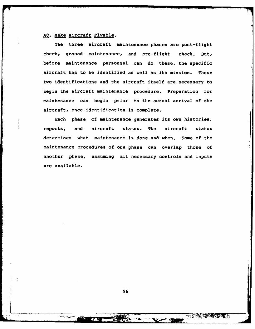
A0, Make aircraft Flyable.
The three aircraft maintenance phases are post-flight
check, ground maintenance, and pre-flight check. But,
before maintenance personnel can do these., the specific
aircraft has to be identified as well as its mission. These
two identifications and the aircraft itself are necessary to
begin the aircraft maintenance procedure. Preparation for
maintenance can begin prior to the actual arrival of the
aircraft, once identification is complete.
Each phase of maintenance generates its own histories,
reports, and aircraft status. The aircraft status
determines what maintenance is done and when. Some of the
maintenance procedures of one phase can overlap those of
another phase, assuming all necessary controls and inputs
are available.
96
to- .

'-
IDENTIFY
AIRCRAFT
1 FORM
A 2T Y P
Id
nDyA i c a t
AIRCRAFT A/C-ID
i IDENTIFY
AC SPECIFIC -AIRCRAFT
~2
Figure 9. A2, Identify Aircraft
A2, Identify Aircraft.
The aircraft identification is constructed from two
pieces of information. This information comes directly from
the aircraft itself. The first piece is the aircraft typ
such as B-52 bomber or F-4 fighter. The second piece is the
specific aircraft identity denoted by the tail number.
These two pieces of information form the specific aircraft
identification for maintenance purposes.
97
ON IM iM&L ;t

A/C-MISSION
C-CMISO
A/C SECURE MAINT-RE
C ~TX
AICAFT- J /S-STTATU,-S
13
Figure 10. A3, Accomplish Post-Flight Check
A3, Accomplish Post-Flight Check.
The post-flight check consists of directing the aircraft,
securing the aircraft, decontamination of the aircraft (if
necessary), and physically inspecting the aircraft. Part of
securing the aircraft can be accomplished prior to the
aircraft's arrival. Once the aircraft is parked, it is made
secure and safe, so that the ground maintenance personnel
can work. Then, decontamination starts and the physical
inspection continues since the inspection starts while the
98
*. ........
Ali=-

aircraft is being secured. (I.e. as the maintenance
personnel work on or around the aircraft they contninually
watch for physical damage or anything out of the ordinary.)
Once the aircraft is safe, physical inspection continues
and/or decontamination begins. Physical inspection of an
aircraft includes examining all surfaces for damage, loose
screws and bolts, checking engines and blades (internal and
external) for damage and foreign debris, checking gauges,
ensuring landing gear and flight controls are within
tolerances, and checking cables for tension and damage.
Decontamination is generally accomplished by hand, by
personnel in the appropriate protective gear. The aircraft
is literally scrubbed down with burshes, soap and water, or
whatever is required to remove the contaminants. The
general consensus is that these protective suits are
cumbersome, awkward, and dangerous in their own right.
However, they are better than nothing! Even though this is
a robot/android scenario, decontamination is necessary if
the crew is to deplane, if the contaminate would damage the
aircraft, or if people must do the repairs on the aircraft.
Once the aircraft is safe for the ground maintenance
crew to start work, and the aircraft status indicates the
need, the ground maintenance work begins.
99

A/C-STATUS A/C-MISSION
A/C LEADAIRCRAFT A/C-STATUS
A/C-ID, A TO PARKING I
APRON1 , A/C-LOCATION
A/C-ID LEADAIRCRAFT A/C-STATUS
A/C TO PARKINGAREA
2 A/C-LOCATION
AC AIRCRAFT
Figure 11. A31, Direct Aircraft
A31, Direct Aircraft. If an aircraft's crew were
unfamiliar with an airfield, the aircraft would be directed
from its landing point to the appropirate taxiway, and
parking aprons. The follow-me or park-on-me normally uses a
vehicle with lights and the appropriate label to lead the
aircraft. All aircraft are directed into their final
parking place since obstacles are usually nearby which can
damage the aircraft or be damaged by the aircraft. This is
called marshalling. Marshalling is accomplished by one or
more individuals with hand-held signal lights used to guide
100i__ _ ___ _ _ _ _ _ _ _ _

the aircraft into its final parking place. This requires
the status of the aircraft with respect to its current
location and its desired location. The final parking place
is reached by following the arm signals of one or more
ground maintenace crew members who compare the distance
between the aircraft, any nearby objects, and the aircraft's
final desired position.
Thus blocks 1 and 2 of A31 would not be required for
every aircraft. The mission of the aircraft could-have a
bearing on where an aircraft is serviced. For example, if
both a test wing and a SAC unit are co-located on the same
base, each would generally have its own maintenance
facilities.
101
h- 1

A/C-STATUS41PERFORM
A/C-ID PRE-ARRIVAL A/C-STATUSSECURITY
CHECK1
A/C-ID PERFORMAA/C POST-ARRIVAL
A/C SECURITY A/C-STATUSvCHECK
A/C-ID ACCOMPLISH A/C-STATUSGROUND MAINT-HISTSAFETY MAINT-REPCHECK
13
Figure 12. A32, Secure Aircraft
A32, Secure Aircraft. Before an aircraft is parked in
its final maintenance parking place, the parking area must
have a security check. Once the parking place meets the
security requirements, the aircraft could be parked, the
final security check is made, and the safety check is
initiated. The initial security check can begin while the
aircraft is still in the air; it must be completed before
the aircraft can be parked. The final security check can
102
JI

not be finished until the aircraft is parked.
Flight lines are always restricted areas, both for
safety and for security reasons. In wartime, security would
be even more imperative since resources would be dwindling
and must be preserved. Maintenance personnel are expected
to challenge unauthorized personnel (those without the
proper badges) when encountered on the flight line at any
time. This involves communication with people, and
manipulation of objects, or equipment. When necessary,
maintenance personnel notify the security police or area
guards of unusual circumstances or request assistance.
Once the aircraft is secure, the maintenance crew begins
the safety check. Certain safety precautions must be done
before others. Safety pins are re-installed in munitions
and external fuel tanks (which have not been dropped) as
soon as the plane lands, prior to entering the apron/parking
areas. Once parked, safety pins are re-installed in the
landing gear to prevent the gear from collapsing; and chocks
are placed around the wheels. Additional safety pins are
installed for the canopies and ejection seats (as needed).
Other safety precautions may need to be taken, depending
upon the aircraft and its condition (such as fuel leaks or
hot brakes), and whether or not the crew or munitions are
still on board. Since the physical inspection begins during
the safety check, one result is a report of discrepancies or
possible damage for further investigation. Part of the
safety check determines whether or not the aicraft requires
103

decontamination at this time. The aircraft status reflects
this requirement.
104
Am~- p--~ ----

p0
ot z
.. zIz- .
.- L) r
mz 4
: 0
00
z 0.
F4:
10

A4, Accomplish Ground Maintenance.
Ground maintenance identifies any component which needs
repair or replacement (including consumables, as required).
A component is an item or subpart of an item which
constitutes part of the aircraft, such as flight controls,
hydraulics, landing gear, engines, black boxes, or air
frames. To accomplish this, ground maintenance personnel
debrief the flight crew members for their comments on the
aircraft and its equipment. This debriefing frequently
occurs while the post-flight check is conducted. Sometimes,
if a problem is elusive, the maintenance crew requests the
flight crew make special observations during the next
flight. These observations are then given to maintenance
during the debriefing. In addition to the flight crew's
comments, the TOs define maintenance checklists for each
aircraft and its components. Once the maintenance crew
receives the above information and has the aircraft
available, each component is located and checked to see if
it meets specifications. This determines the condition of
the component. Then, as required, the components not
meeting specifications are replaced or repaired. Before
certifying the component fixed, it is rechecked to ensure it
meets specifications. If the repaired/replaced component
meets specifications, then the next component is checked and
the cycle is repeated. If the fixed component does not meet
specifications, then it is rediagnosed to determine the
problem and the requirements to fix it. This procedure
106

reprts are updated "continuously", while the written
-~ EEE~ ~ oreports and histre r copihdl triTe statusmof
the aircraft is dependent upon the status of its components.
107

TOs
A/C-STATUSCHECK MAINT-HIST
A/C-ID COMPONENT |AINT-REP
A C TOLERANCES COMP-COND
CONSUM4ABLE COMP-CONDA/C-ID REPLENSIH MAINT-HISTYA/C CONSUMABLES MAINT-REP
A/C-STATUS
Figure 14. A44, Determine Component Condition
A44, Determine Component Condition. The current
condition of the component must be compared to the TO's
specifications. If the aircraft component matches the TO
specification (within the acceptable variance), then the
component is 'good'. If the component meets the TO
specifications, but containes consumables which require
replenishing, then the consumables are replenished. If the
component does not meet the TO specifications, then it is
'bad' and must be repaired or replaced. If the mission of
the aircraft requires additional equipment or supplies from
maintenance which are not usually needed but are needed for
this particular mission, these would be supplied now. This
thesis defined These as mission particular resources.
108

C I DDI PRBE
SPARES i P AIRMAIN I
2,
SPARES REPLAC MAINT-HISA/-COMPONENT MAINT-REP
Figure 15. A45, Fix Bad Component
A45, Fix Bad Component. Fixing a bad component consists
of either replacing or repairing it. Once a component is
labeled as 'bad', the cause has to be diagnosed in order to
fix the component. Whether the component can be repaired
on-site, or must be replaced is determined. Then, once the
component is thought to be fixed, it again has to be checked
against the To specifications. A replacement could be
faulty, or the cause of the bad component might be due to
compound causes. If the fixed component meets the TO
specifications, then the next component is checked. If that
is the last component to be checked, then the reports and
109

status are updated as required.
Repairs are done as necessary. While some repairs may
be temporarily postponed, such as a small brake fluid leak
(found during a pre-flight check); others must be made
immediately, such as fuel leaks (anytime), or hot brakes
(normally occur during post-flight check). The danger of a
fuel leak should be obvious to everyone--an explosion and/or
fire. Hot brakes can be just as dangerous because of
explosion and possible fire as well.
Many repairs are modular, that is, a malfunctioning box
of equipment can be pulled out (also called 'unplugged') of
the aircraft and be replaced with one functioning properly.
This is referred to as 'black box' maintenance by the
maintenance personnel. Some are not, such as repairing a
flat tire. A flat tire must be repaired because an aircraft
cannot safely take off with a flat tire. An aircraft can be
landed safely with a flat tire, however. Maintenance
personnel know (via TOs, training, and experience) the
location of the components to be checkeO and how often to
check them for damage.
Once ground maintenance clears an aircraft as ready to
fly, the next stage before an actual flight is the
pre-flight check. This can occur right after ground
maintenance was done, or may be days later. The pre-flight
check is accomplished just prior to the aircraft's flight.
110I ________ ______________________________________

A/C-STATUS
ACCOMPLISHA/C-ID REFEJEL STATUS
REAM
A/C-ID APPLY MAINT-REPEXTERNAL
A/C-STATUSID POWEMR
12 j
MAINT-REPA/C-ID INSPECT MAINT-HISTC iAIRCRAFT A/C-STATUS
3
IF
A/C-ID ACCOMPLISH A/C-STATUSA/C AIR SAFETY MAINT-HIST
CHEEK MAINT-REP
.4
Figure 16. A5, Pre-Flight Check

A5, Accomplish Pre-Flight Check
The refuel and rearm sequence must be determined for
each aircraft, and the aircraft must be physically
inspected, external power applied to the aircraft, and the
aircraft must be made safe for flight. These are the major
duties accomplished during the pre-flight check. The
physical inspection, the external power hookup, and parts of
the pre-flight safety check can be accomplished before,
during, or after refueling or rearming and in any convenient
sequence.
Prior to take-off, a portable power plant is hooked up
to the aircraft. This supplies electric power for the
aircraft until the engines are running. An 'air pusher' may
be required to be hooked up to some fighter engines as well
as the electric power. Once the engines are started and
running under their own power, the power plant is
disconnected. At least one cable runs from the power plant
to the aircraft. The attachment point on the aircraft is
similar in appearance to a power outlet/wall socket. The
'air pusher' has a large flexible tube which attaches to the
engine, so that air can be forced into the engine.
Maintenance personnel know what the power and engine
starting requirements are for an aircraft. Then, using the
proper power plant, the power cables are plugged into the
correct recepticles, and the proper engine starter
mechanisms are attached.
The physical inspection is the same as during the
112
__________
0~!

post-flight check as discussed in A3. If damage is found or
suspected which can not be remedied immediately, the
aircraft returns to the "ground maintenance required"
status. The air safety check is just the reverse of the
ground safety check. Primarily, the landing gear pins,
engine covers, and chocks must be removed. The canopy and
ejection seat pins must be removed. The munitions pins and
fuel tank pins are removed, as well, but not until just
before the plane takes off (to prevent any accidents on the
landing apron or parking area). Thus, the maintenance
personnel ensure the aircraft is ready (and safe for flight)
by removing the ground-required safeguards. Once the
maintenance crew signals the flight crew that maintenance is
complete and the flight crew takes control, the aircraft's
mission is considered started--even before the aircraft
physically takes off. Thus, if the aircraft's mission is
aborted after the flight crew takes command, the aircraft
reverts to the post-flight check. This is true, even if the
aircraft never leaves the ground.
113
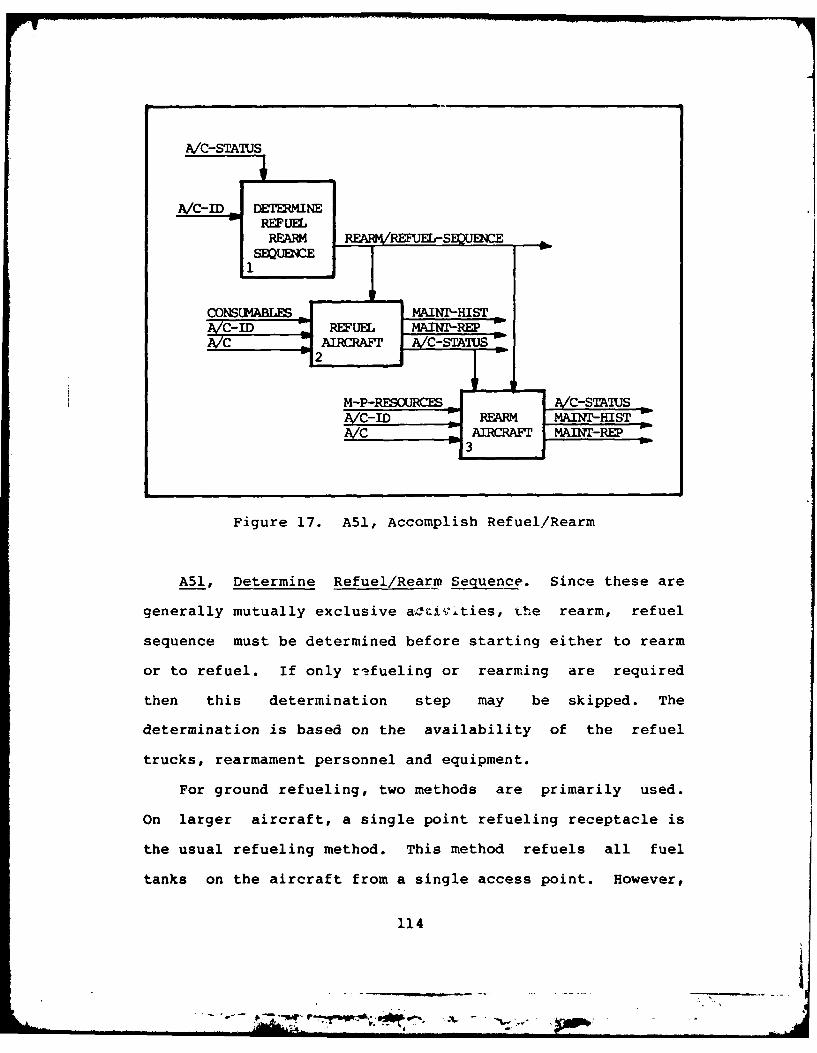
A/C-STATUS
Ac- ID DETEMINERRM Rmmm SKMENCE
lSEQU~E
C-0~ " REFUEL AN-EA/C- AIRCRAF ---TAU2iL M-REARM_ MAi-Hs T
AC AIRRAF MAIM-REP
Figure 17. A51, Accomplish Refuel/Rearm
A51, Determine Refuel/Rearm Sequence. Since these are
generally mutually exclusive aoCiv;Lties, the rearm, refuel
sequence must be determined before starting either to rearm
or to refuel. If only re fueling or rearming are required
then this determination step may be skipped. The
determination is based on the availability of the refuel
trucks, rearmament personnel and equipment.
For ground refueling, two methods are primarily used.
On larger aircraft, a single point refueling receptacle is
the usual refueling method. This method refuels all fuel
tanks on the aircraft from a single access point. However,
114
__________
- A *f'?-.~?* .. -

smaller aircraft are filled, using a fuel hose with a
nozzle, in a manner similar to that used to refuel
automobiles. Each fuel tank must be filled separately,
through separate access points. The larger aircraft are
able to use this second method when the single point
refueling method is not available. This can be accomplished
since each fuel tank on the larger aircraft has individual
access points, as well as the single access point.
Maintenance personnel know the method for refueling, and the
type of fuel for each aircraft serviced (this information is
learned from the TOs and technical training).
In wartime, as long as bombs, other munitions, and the
aircraft to carry them are available, the aircraft has to be
resupplied. Thus, based on the particular aircraft, and its
mission, the maintenance personnel know whether or not to
contact the munitions personnel for the armaments required.
115
_ ., 7 , ., 4 . . .

Appendix B
Data Dictionary
a/c = A/C = aircraft
aircraft = the physical, individual
aircraft. Alias: a/c, A/C
aircraft-identification = a/c-type + specific-a/c.
Alias: a/c-ID, A/C-ID
aircraft-location = the physical location of the
aircraft including its
location with respect to
nearby objects of interest.
Alias: a/c-location,
A/C-location, a/c-loc,
A/C-loc
aircraft-mission - what the aircraft is
scheduled to do next. Alias:
a/c-mission, A/C-mission
aircraft-status = current state (status) of the
aircraft. Possible values
(not all inclusive):
in-ground-maintenance,
in-post-flight-check,
flyable-a/c, aircraft-parked,
aircraft-location,
116
LL_

additional-ground-maintenance
required, aircraft-secure,
pre-flight-check-complete.
Alias: a/c-status,
A/C-status
aircraft-type = the type of aircraft.
Possible values (not all
inclusive): B52 bomber, F4
fighter, KC135 tanker.
Alias: a/c-type, A/C-type
component = a physical item or part on or
removable from the aircraft.
Alias: comp
component-condition = the current state of each
component after comparison to
the technical order
requirements. Alias:
comp-cond
component-identification = a unique identifier for each
component which denotes which
specific aircraft and which
particular component on that
aircraft. Alias: comp-ID
component-name = the name of the component as
it appears on checklists and
the inventory lists. Alias:
comp-name
117
.. ..... ........

consumables = those items which are needed
for each and every aircraft,
each and every mission.
diagnosis = what is thought to be wrong
with a component.
maintenance-history = the record of maintenance by
part and malfunction or
intolerance of each component
and aircraft. Alias:
maint-hist, Maint-Hist
maintenance-reports - those reports which
maintenance is both required
and requested to make orally
or written. Alias:
maint-rep, Maint-Rep
mission-particular-resources = those items which are needed
by an aircraft to accomplish
its particular mission.
Alias: M-P-Resources
refuel/rearm-sequence the sequence in which
rearmming and refueling will
be accomplished; since, one
may only be done after the
other is complete. The order
does not matter. Alias:
refuel/rearm-sequence,
refuel/rearm-seq
118
---- - - , ,- - - - n -'a~~_ - ---

spares = those items required by
maintenace to bring the
aircraft and its components
to flyable status.
specific-aircraft the unique aircraft as
identified by tail number.
Alias: spec-a/c, spec-A/C,
Spec-a/c, Spec-A/C
TO(s) = Air Force Technical Order(s)
119
I 0

Appendix C
Audio Cassette Recorder Programs
(13 July 1982: Version 2.4)
These programs were modified by Roz Taylor; based on the
original programs as provided in the MMD-1/MI Operating
Manual by E&L Instruments, Inc. The modifications were
necessary to use the MMD-l/MI as configured at AFIT.
The following routines were used with the MMD-l
configured with the Memory Interface Board. Each section of
code starts with an even "octet". When the code is
finalized, the trailing NOPs should be removed and the total
code made more compact. This would result in addresses
being changed within the code. It was deemed at this time,
unnecessary to accomplish these changes prior to finalizing
the code. The code which follows works, but may not be the
most efficient method.
RAM LOAD/DUMP PROGRAM
This is a listing of the Loader/Dump Program which when
resident, is located in the main board RAM (RAM PR"2"). The
PROM LOAD/DUMP PROGRAM exists, however it was not used
because the PROM location interfered with the special
programming installed in this particular version of the
MMD-1/MI.
120
_____

READ FROM CASSETTE ROUTINE (RCAS): This routine reads the
data from the cassette tape and stores it in sucessive
memory locations starting with 030 000. As the data is
input, it is displayed on the MMD-l LEDs (port 2). The
address is displayed on the MMD-l LEDs via ports 1 and 0.
Control is returned to the CRT monitor when transfer is
complete. START CASSETTE RECORDER BEFORE USING THIS
ROUTINE. Modification suggestion: add the ability for user
to specify number of blocks of code to be moved into memory,
as in the write to cassette routine.
MEMORY CODE LABEL MNEMONIC COMMENTSLOCATION002 000 041 RCAS: LXIH Initialize the mem-002 001 000 ory pointer: H=030002 002 030 and L=000.002 003 315 CALL002 004 170 INPUT002 005 002
002 006 Thru 002 010 000 NOP (This was wherea previous bit of code was--but eliminated,later)
002 011 333 IN Clear flags if002 012 022 necessary.002 013 315 NEXTIN: CALL Input a byte of002 014 100 CASIN data into the002 015 002 accumulator from002 016 167 the cassette tape.002 017 315 CALL002 020 220 DISPLAY002 021 002002 022 043 INXH Increment the mem-002 023 174 MOVAH ory pointer, load002 024 272 CMPD new high address002 025 302 JNZ value and check for002 026 013 NEXTIN end of loop. If not002 027 002 end, get next byte.002 030 303 JMP When done loading002 031 240 CRT return to the CRT002 032 002 monitor.
002 033 thru 002 037 000 NOP
121
* -- *i ..

********* ***************************************************
WRITE ONTO CASSETTE TAPE ROUTINE (WCAS): This routine
stores the data on cassette tape. The user selects from 1
to 8 blocks of data. Each block consists of 377 (octal)
bytes of memory, starting at 030 000. Once the routine
starts, the desired number of blocks is entered by the user
via the HEX pad on the MMD-l. Use 0 to indicate 8 blocks.
After a 22 second delay, the data is written onto the
cassette. Once the data is written to tape, control is
returned to the CRT monitor. START THE CASSETTE RECORDER
BEFORE USING THIS ROUTINE.
002 040 041 WCAS: LXIH Initialize the mem-002 041 000 ory point to H=030002 042 030 and L=000.002 043 315 CALL Wait for user to002 044 170 INPUT input number of002 045 002 bytes to be trans-002 046 315 CALL ferred. Delays002 047 140 DELAY the start of the002 050 002 data transfer.
002 051 Thru 002 053 000 NOP (Unnecessary coderemoved)
002 054 176 MORE: Get data from mem-002 055 315 CALL ory (accumulator)002 056 120 CASIN output and load to002 057 002 cassette tape.002 060 315 CALL Display each byte002 061 220 DISPLAY data and its add-002 062 032 ress on ports #2,
1, and 0002 063 043 INXH respectively.002 064 174 MOVAH Increment the high002 065 272 CMPD address byte and002 066 302 JNZ check for end of002 067 054 MORE data. If not end,002 070 002 get more data. If002 071 303 JMP end, return to CRT002 072 240 CRT monitor routine.002 073 002
002 074 Thru 002 077 000 NOP
122

CASSETTE INPUT ROUTINE (CASIN): This routine waits for data
to be received by the cassette recorder UART, and inputs the
data into the accumulator.
002 100 333 CASIN: IN Check the cassette002 101 023 UART status bits.002 102 037 RAR002 103 322 JNC Recheck the cassette002 104 100 CASIN UART status bits002 105 002 until data is avail.002 106 333 IN Input data to the002 107 022 accumulator.002 110 311 RET Go back to where002 111 000 NOP CASIN was called.
002 112 Thru 002 117 000 NOP
123

CASSETTE OUTPUT ROUTINE (CASOUT): This routine waits for
the transmitter holding register to say it is ready for the
next data byte. The routine then outputs the data to the
cassette.
002 120 365 CASOUT: PUSHPSW Save the data.002 121 333 IN Check the transmit-002 122 023 ter status bits.002 123 346 ANI002 124 004002 125 312 JZ Recheck the trans-002 126 121 CASOUT+1 mitter status bits.002 127 002 (But do NOT try to002 130 361 POPPSW "resave" the prog002 131 323 OUT status word.)002 132 022 Once the transmitter002 133 311 RET status says it is002 134 000 NOP ready, return the002 135 000 NOP data to the ouput002 136 000 NOP port to send to the002 137 000 NOP cassette recorder.
124
4

DELAY PROGRAM CONTINUATION ROUTINE (DELAY): This is a time
delay. As programmed, the delay is for about 22 seconds.
If the value ("001n) in location 002 144 is changed to
"000", then the time delay is only about 12.2 seconds (not
quite a drop by half).
002 140 365 DELAY: PUSHPSW Save the registers.002 141 305 PUSHB002 142 001 LXIB Load the following002 143 364 value into Reg. B.002 144 001 This value changes002 145 315 CALL the time duration.002 146 277 KTS KTS=THE KEX TIMEOUT002 147 000 SUBROUTINE (comes002 150 013 DCXB with the MMD-I).002 151 170 MOVAB When count is not002 152 261 ORAC zero, recall the002 153 302 JNZ KTS. (Do NOT do002 154 145 DELAY+5 all those saves/002 155 002 loads again!)002 156 301 POPB When time is up,002 157 361 POPPSW restore all saved
registers.002 160 311 RET
002 161 thru 002 167 000 NOP
125
S . ,... n

INPUT NUMBER OF DATA BLOCKS TO BE MOVED ROUTINE (INPUT):
This routine allows the user to enter a single digit number
from the HEX keyboard on the MMD-l/MI. Only the numbers
from 1 -> 8 are accepted. Use a "0" to denote the number 8.
If more than 8 blocks of data are to be loaded via this
method, the loading routine will have to be repeated for
each set of 8 or less blocks with appropriate changes in the
load routine to allow for the memory location differences.
002 170 315 INPUT: CALL002 171 315 KEX002 172 000002 173 376 CPI Check for a number002 174 010 from 0 -> 7, input002 175 322 JNC by the user.002 176 170 INPUT If not, go back and002 177 002 try again.002 200 267 ORAA Set flags.002 201 302 JNZ002 202 206 NOTO002 203 002002 204 306 ADI Add 8, if the zero002 205 010 key were input.002 206 204 NOTO: ADDH Compute stopping002 207 127 MOVDA address; save it002 210 311 RET in Reg. D. Go002 211 000 NOP back to where002 212 000 NOP called from.
002 213 Thru 002 217 000 NOP
126
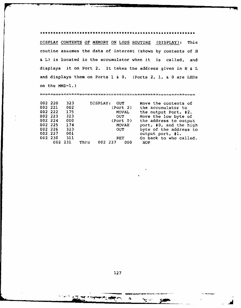
DISPLAY CONTENTS OF MEMORY ON LEDS ROUTINE (DISPLAY): This
routine assumes the data of interest (shown by contents of H
& L) is located in the accumulator when it is called, and
displays it on Port 2. It takes the address given in H & L
and displays them on Ports 1 & 0. (Ports 2, 1, & 0 are LEDs
on the MMD-I.)
002 220 323 DISPLAY: OUT Move the contents of002 221 002 (Port 2) the accumulator to002 222 175 MOVAL the output Port, #2.002 223 323 OUT Move the low byte of002 224 000 (Port 0) the address to output002 225 174 MOVAH port, #0, and the high002 226 323 OUT byte of the address to002 227 001 output port, #1.002 230 311 RET Go back to who called.
002 231 Thru 002 237 000 NOP
127
sotI

RETURN CONTROL TO THE CRT MONITOR ROUTINE (CRT): This
routine initializes the stack pointer, resets he MMD-I, and
returns control to the CRT monitor routine. If user is
concerned about resetting to the beginning of the Audio
Cassette Recorder Programs, change program contents for 002
244 and 002 245 to the starting address of "free" memory.
002 244 is the low byte and 002 245 is the high byte of the
address.
002 240 061 CRT: LXI Give the stack pointer002 241 000 SP the value 4. (i.e.002 242 004 initialize the "SP".)002 243 041 LXIH Load the starting add-002 244 000 ress of user access-002 245 002 ible memory into H&L.
This is equivalent tousing the RESET buttonon the hex pad of theMMD-l.
002 246 176 MOVAM Move the contents ofthe addressed memorylocation into theaccumulator.
002 247 315 CALL Display the contentsof memory on the MMD-I
002 250 220 DISPLAY LEDs.002 251 002002 252 303 JMP Go to the CRT monitor002 253 000 routine (found in KEX002 254 001 routines in MMD-l).
002 255 Thru 002 257 000 NOP
128

BOOTSTRAP ROUTINE (BOOT): This routine loads the previous
code (already on tape) from tape into the memory addresses
given above. This routine must be entered, by hand, each
time the MMD-l/MI unit loses power. Unfortunately, the
MMD-1 does NOT have continuous memory. NOTICE: THIS
ROUTINE IS LOADed and executed from HIGH MEMORY!!!!! Do not
tell how many bytes you want to transfer. When all MMD-1
LED lights go dark for more than 5 seconds or all are lit
for more than 5 seconds, the tape is through loading.
030 000 041 BOOT: LXIH Initialize the memory030 001 000 pointer to starting030 002 002 address of audio cas-
sette RecorderPrograms.
030 003 333 IN Clear flags, if030 004 022 necessary.030 005 333 NEXTIN: IN Input status bits.030 006 023030 007 037 RAR030 010 322 JNC Jump back if no data030 011 005 NEXTIN available, yet.030 012 030030 013 333 IN Input data.030 014 022030 015 167 MOVMA Store the data030 016 323 OUT Output the data and030 017 002 address to Port #2.030 020 175 MOVAL Move the low address030 021 323 OUT byte to accumulator030 022 000 and output to Port #0.030 023 174 MOVAH Move the high address030 024 323 OUT byte to the accumula-030 025 001 tor and display on
Port #1.030 026 043 INXH Increment the memory030 027 303 JMP pointer and then get030 030 005 NEXTIN more data.030 031 030
129
,_ .

The MMD-1/MI Operating Manual lists the code for three
routines which were part of the AFIT KEX/MONITOR adaptation.
These routines were TTYIN, TTYOUT, and RDRIN. These were at
000 164, and 000 201 respectively. Since RDRIN was for a
paper tape reader input subroutine and was omitted from this
work as unneeded. It was not included in the AFIT
modification of the KEX/MONITOR program, as well.
130
_W..
-Io' ..
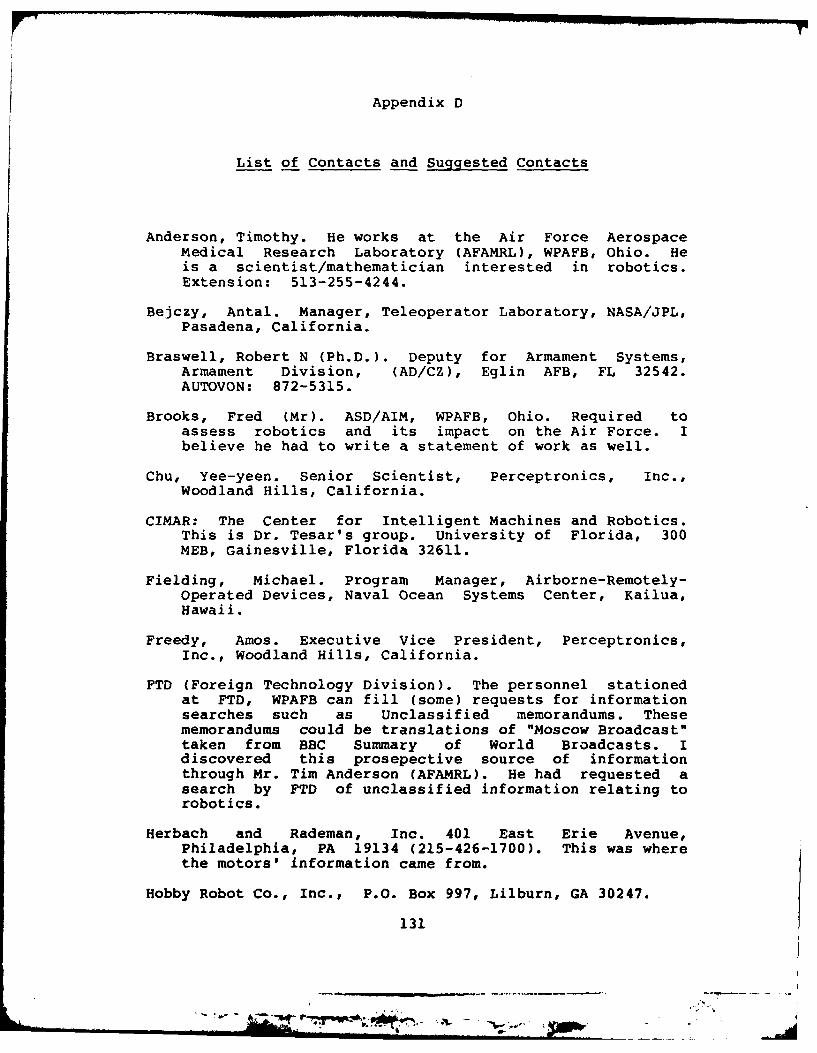
Appendix D
List of Contacts and Suggested Contacts
Anderson, Timothy. He works at the Air Force AerospaceMedical Research Laboratory (AFAMRL), WPAFB, Ohio. Heis a scientist/mathematician interested in robotics.Extension: 513-255-4244.
Bejczy, Antal. Manager, Teleoperator Laboratory, NASA/JPL,Pasadena, California.
Braswell, Robert N (Ph.D.). Deputy for Armament Systems,Armament Division, (AD/CZ), Eglin AFB, FL 32542.AUTOVON: 872-5315.
Brooks, Fred (Mr). ASD/AIM, WPAFB, Ohio. Required toassess robotics and its impact on the Air Force. Ibelieve he had to write a statement of work as well.
Chu, Yee-yeen. Senior Scientist, Perceptronics, Inc.,Woodland Hills, California.
CIMAR: The Center for Intelligent Machines and Robotics.This is Dr. Tesar's group. University of Florida, 300MEB, Gainesville, Florida 32611.
Fielding, Michael. Program Manager, Airborne-Remotely-Operated Devices, Naval Ocean Systems Center, Kailua,Hawaii.
Freedy, Amos. Executive Vice President, Perceptronics,Inc., Woodland Hills, California.
FTD (Foreign Technology Division). The personnel stationedat FTD, WPAFB can fill (some) requests for informationsearches such as Unclassified memorandums. Thesememorandums could be translations of "Moscow Broadcast"taken from BBC Summary of World Broadcasts. Idiscovered this prosepective source of informationthrough Mr. Tim Anderson (AFAMRL). He had requested asearch by FTD of unclassified information relating torobotics.
Herbach and Rademan, Inc. 401 East Erie Avenue,Philadelphia, PA 19134 (215-426-1700). This was wherethe motors' information came from.
Hobby Robot Co., Inc., P.O. Box 997, Lilburn, GA 30247.
131
Jig-

Johnson, R. T. Professor at University of Missouri-Rolla(was the Missouri School of Mines). He is involved withthe fledgling robotics program at UM-R. His phonenumber is 314-341-4614. The Department of Mechanicaland Aerospace Engineering Chairman's phone number is314-341-4662, while the general faculty phone number is314-341-4661. The address is:
Department of Mechanical and Aerospace EngineeringMechanical Engineering BuildingRolla, MO 65401
Dr. Johnson noted in a letter (to me) that if his"limited" experience would benefit me, to call.
Kessler, Bill. A Ph.D. working at WPAFB, Ohio which Dr.Tesar suggested as someone locally to talk to aboutrobotics, the U of F, and Dr. Tesar's work. I got theimpression that Dr. Tesar has had "dealings" with Dr.Kessler, previously.
Langendorf, Lt. Col. Henry. Chief, AI/Robotics Division,TRADOC, Fort Benjamin-Harison, Indiana.
Lyman, John. Professor and Chairman, Engineering SystemsDepartment, School of Engineering and Applied Science,UCLA. "Professor Lyman has participated in research,development and application of high-technology roboticsysstems, including teleoperator andd limb prosthetics,for more than 25 years. His special interest is in thehuman-equipment interface for complex, addaptivemachines."
Madni, Azad. Director, Robotics and Automation Systems,Perceptronics, Inc., Woodland Hills, California. "Dr.Madni is currently principal investigator on a NavyRobotics R&D program directed toward the design anddevelopment of an intelligent robotic platform for U.S.Marine Corps reconnaissance and surveillance needs. Healso serves as an advisor to the U.S. Army ResearchInstitute Robotics/Artificial Intelligence Program. Dr.Madni has been principal investigator over the last fouryears on several DARPA projects in man-machinerelations, user models in information prioritization andselection tasks, advanced methods for informationdisplay, and videodisc-based low-cost portable trainingsystems."
Mayer, Lt Gordon E. Lt Mayer is the Projects Manager,Materials Laboratory, Wright-Patterson AFB, Ohio. Hehas his M.S. in robotics from Purdue University (1979).His thesis was on the Kinematic Design/Control ofManipulators. He worked most of 1979 for Unimationprior to coming on active duty (Air Force).
132
* . a , ,. ,,.. i -

Montgomery, Jerry g. Lt, USAF. Currently assigned to ASDat WPAFB, Ohio. Was an M.S.E.E. student in patternrecognition under Dr. Matthew Kabrisky at AFIT. He is"local expert" on fuzzy set theory and fuzzy statistics.ASD/BILE, 513-255-4044.
Motors (6-12V-DC). These motors were found in a BrevelStock Motors catalog. These were purchased from:
Reserve Electric,(Mike Evans, Sales Engineer)2090 E. 19th Ave,Cleveland, Ohio216-771-5764
RB Robot Corporation. Produces the RB5X robot (withbatteries for $1195. "The company expects computer andelectronics engineers and hobbyists to buy the robot asa starter system for further robotics development. For$1195, the robot you get is blind, deaf and dumb. Itsonly sensory apparatuses are feely bumpers that tell itwhen it has run into an object. They provide tactileinput for the robot's learning programs .... [it] has astandard RS-232 serial interfface.... [it has] an optionpackage with sonar, pulsating light and extra memory,for $295" (Infoworld, 1982). The company is located inGolden, Colorado.
Roboticon. Name of seminar "series" on robotics. Can beofferred "in-house". For more information, contact:
Registrar, Roboticon157 East Valley Parkway, Suite 2BEscondido, CA 92025
Saveriano, Jerry W. President, Saveriano & Associates,Huntington Beach, California.
Tallen, Norman. A Ph.D. working at WPAFB, Ohio which Dr.Tesar suggested as someone locally to talk to aboutrobotics, the U of F, and Dr. Tesar's work. I got theimpression that Dr. Tesar has had "dealings" with Dr.Tallen, previously.
Tesar, Delbert. Director of CIMAR, University of Florida,300 MEB, Gainesville, Florida 32611. Dr. Tesar willusually provide copies of his material upon request.904-392-0814 (He was also quite good about returning mytelephone calls; but, I tried not to abuse that either!)
UCLA Extension. A short course program was offerred at UCLAon 11-14 January 1983, entitled "Smart Systems and HumanFactors in Battlefield Robotics". The coordinators andlecturers were John Lyman (PhD) and Azad Madni (PhD).Other lecturers were Antal Bejczy (PhD), Yee-yeen Chu(PhD), Michael Fielding (MS), Amos Freedy (PhD), Lt Col.
133
- A ~ .. ~ - - . ~ - - - -ll

Henry Langendorf, and Jerry W. Saveriano (MS). Each ofthese lecturers and their "addresses" are listedseparately. This was a four day course, EDP No. E4719V,Course No. Engineering 839.42, 2.4 CEU. Mailing listaddress is:
Mailing Lists, UCLA ExtensionsP.O. Box 24901Los Angeles, CA 90024
Perhaps lecture notes or other information would beavailable, if requested. The intent (quoted from themailing list brochure) was "for managers ofrobotics/automation programs, developers of advancedweapon systems, researchers in the field of intelligentautomation, C3 system designers and human factorsengineers." The purpose "provides new concepts,methodologies, and specific technologies which aredirectly applicable to the development and realizationof smart weapon systems for 1990-2000 time frame. Itintroduces generic approaches that should allow systemdevelopers to meaningfully apply state-of-the-arttechniques in human factors engineering and man-machineinterface design, advanced automation and expertsystems, user models and information management aids tovarious current and projected application areas inbattlefield robotics.
134
t.,
AN- W

Appendix E
DC Gearmotor Specifications
135
I~a ___________ ________ ______

BREVEL
D.C. GEARMOTORSSERIES 14R
In 14R D C Ge,rn is -d hbeI. o ocred m ai Puclj tp dl,- door . ol' In Opnentldr04speed oprtnand hrgn ltorquet Or d,,s,,4 If I, parlc.arln machines. Wmanylo other, Win" ther firn or1 .1erforrm
500 tp'lrs.r."t .eQurrrg hrgh starting 1orqu,..n.t aice ive req..,.d we ..ll desgn to "Is it* aptplst"I~n andba ""oi Cutcontrol .00,itve-bi.ty Tvpcjl aPtl,,U Iarn,lh a Quotat-On after C)c,,aeesecla~o are -,-snd
t~Ortsttl am--l~sllgm, business al.h-rn,. -IDcr
MECHANICAL CONSTRUC71ON4 ENGINEERING DATAGEAR CASE Ga., IuIIv erto i n hiy.1an trwtced, SPEED RANGE 0 5 to 400RAP M
cl 1"y"rlng it C alloy' die ceatifl TOROUE #p to 751 bt ., hie, a~~ederpond-rr utr
BEARINGS Output .- Id A,-.e belaing, 1 a ,e p.,Ild, duty CyleSotered rrme, I Arotaturo Bearingt t sotl I gnng ath ELECTRICAL SPECIFICATIONS.large 0,1 "-sco-rt Inerret gerur 1.on hardcenedarmd grund Steel pr1 hctelh.d f d.,castng SUPPLY VOLTAGE 601.o48 Volts
GERN oralrtrpno adIera oncs oeo TERMINALS 314 Male OurbConctor,
III:r~ got' tot n ur Ic,Or tlnd,,rdI Spur q..rs andp....' ate .sd in other stage, Gears and Pmnsn ae OPTIONAL FEATURES
tWal .. t. is1 .tf tto N l~ gertI TW , ' otlairg be Mountrtr Corlgoatrion Four HoOes 10-32. 114 20 Tapout pot peed o an ee gr, acoon .170 Tttro
outut w* Elictr.ica T 1orntmars 110 bh~de Mail Ourc COnnectOUTPUT SHAFT Caehree 04tle te.'~Termnal, or Leads so Suit
%" tottgrs standard *Tedhm.,"eOutput DC VlaeP~otorlt peBRUSHES Copper-rpers writh Cott Sprrng% is startdard *otuShl ontivirUpo38"0Dwhfac
Blutkt replaceable .thtrou drs1aetblrtg motor. *Outp,n ot. ernlo. Up it 3/SOD ~ttr lt.OFAN SHAFT: Rear motor eisennson oll 181111 Dia Cosrle oe.Itra rEtra hed.Ra
MOUNTING Four 0B 32 Tap t oW olesstndarri Extentrson. or Othte Features to Suit Stainless SteelMaternal and Other Corrosroer Protrictit Avaloble
oRatet to rgrrtertt Bllir NO 40 l0t Oddr.onaI
All satici,catrons tablect to change without not~ce. lausawelon the 41,00 motor.
136
- Orn A'V ~ ---- -- A_

4 THE DESIGNS SHOWN ON THIS PAGE ARE SPECIAL DESIGNS CAN BE ENIEEE
READILY AVAILABLE FROM STOCK. TO MEET YOUR SPECIFIC APPLICATION.
AU, ... .... . n .. .. .........
o .. . +° I' ...T s
I.,, a.
j ooQ- , a...
01-o 0 0O! 0 0
00
00
30 TI7II.30.0 ........... ED ~
* o -u't s -t - s o ro---i-t
,o -I X
01
0o 10 20 30 40 0 00 10 20 30 40 50TORQUE L-rIN TORQUE La-au
300 MO SPEED IN MOTO CURRENT
200
0 *" l0 5 10 15 20 as 0 10 20 30 40 50
TORQUE Li IM TORQUE LO IN
BREVEL MOTORS INC. C072
sub sld i ry o f - T E LE PH O N E 120 11 33 0220
VERNITRON CORPORATION TELEX 640
137
-$Oi

Z E,
LU~~ 000
ci .. . . . . . . .. . . . .rrz Z
C0 fi 2;-f !SZE•
E i Fee
138II , ,I
i ! !ll a . . i.l' yI-
* -© oaI
III
II.-o c aj Lr-~ - a- ll~ll~lll
- a+si' I :: ! i| i
_ .li. i I !.. - :;
1 I 4, w. I,-- -, : - .i.. . "0 -
138 '
- "--- I. .. ._ .
.. . . ' I- . . . ..
Vita
Roslyn J. Taylor was born on 8 August 1949 in San
Francisco, California. She graduated from high school in
Lebanon, Oregon in 1967 and attended Oregon State University
from which she received the degree of Bachelor of Science in
Chemistry in June 1973. In 1977, she entered Officer
Training School and received her commission in the USAF.
Upon receiving her commission, she attended the basic
Communications-Electronics Officer Course at Keesler AFB,
Mississippi. Upon graduation from technical school, she
became the Chief of Quality Assurance for the 2046
Communication and Installation Group at Wright-Patterson
AFB, Ohio, and then the Communications-Electronics Plans and
Programs Officer for the 2046th CIG. In August 1979, she
entered the newly organized Electrical Engineering
Conversion Program offerred in residence at AFIT. In June
1981, she received the degree of Bachelor of Science in
Electrical Engineering, whereupon she remained at AFIT to
continue her studies in electrical engineering.
Permanent address:
34133 Tennessee Road
Lebanon, Oregon 97355
139
Ali PIP%,_ _ i

SECURITY CLASSIFICATION OF THIS PAGE (Whee, Data Prt,led)
I READ INSTRUCTIONSREPORT DOCUMENTATION PAGE BEFORE COMPLETING FORMIREPORT NUMBER 1 jp
AFI T/GE/EE/83M-3 a515 . 3 RECIPIENT'S CATALOG NUMBER
4. TITLE (and Subtitle) 5 TYPE OF REPORT IS PERIOD COVERED
An Android Research and Development M.S. ThesisProgram6 PERFORMING ORG. REPORT NUMBER
7. AUTIHOR(s) 9. CONTRACT OR GRANT'NUMBER(s)
Roslyn J. TaylorCapt. USAF9. PERFORMING ORGANIZATION NAME AND ADDRESS 10. PROGRAM ELEMENT. PROjECT, TASK<
Air Force Institute of Technology AE OKUI UBR
Wright-Patterson Air Force Base, Ohio 454-,
It. CONT ROLLING OFFICE NAME AND ADDRESS 12 REPORT DATE
"!AR 8313. NUMBER CF PAGES
14L7I&. MONITORING AGENCY NAME & ADDRESS(if different fram Controlling Office) IS. SECURITY CLASS (.1 I!. reP-r
U n classi f ie d
15a. DECLASSIFICATION DOWNGRADINGSCHEDULE
16. DISTRIBUTION STATEMENT (of this Report)
Approved for public release; distribution unlimited.
7. DISTRIBUTION STATEMENT (of the abstract entered in Block 20. it different from Report)
IS. SUPPLEMENTARY NOTES 1I~e ~I~: AW Aft IM7A r XVEil e
AIII rRs arcli 'd Prtssoo Devoop "Ma1kFow Institule of Techoolagy (ATC)I-WRzhliatP010190 ALFS Oil 45433
19. KEY WORDS (Contfinute on revearse side If necessary and identify by block number)
Android, Robot, Research ProgramResearch, Development,Clearing House
20. AUST ACT (Continue on reverse side If necessary and identify by block number)
-This report identifies areas requiring further researchto develop a detailed research and development plan for anaircraft maintenance android. The general user requirementsare defined and the desired android capabilities are addressedto meet the defined user requirements. The user requirementsare defined independently of aircraft type. Structured analysisdiagrams are used to describe the functional requirements.Sneifit -crmg~sin re made.,
DD JA 7 1473 EDITION OF I NOV AS IS OB3SOLETE ~'Kncla SsiiedSEUIYYCL I FSCAfTIO THIS PAGE '"I'len Data. Enreed

I