angle and flat bar line - controlled automation
TRANSCRIPT

ABL-100
ANGLE AND FLATBAR LINE

501-557-5109 • www.controlledautomation.com • [email protected]
ABL-100
The ABL-100 is the most versitie, and fastest angle and flat bar punching and shearing machine on the market today. The high speed servo motor, continuous probing, continuous clamping, advanced servo and valve positioning software make it not only fast but very accurate. The ABL-100 is offered by Controlled Automation with such options as, 115 ton or 143 ton single or double punches, single or double cut shear options ranging from 215 tons up to 425 tons, dual shear machine models, a variety of length measurement options as well as part marking and stenciling unit options.
(optional dual shear model shown)
Machine with material flow from left to right, single punches and single 425 ton single cut shear shown.

501-557-5109 • www.controlledautomation.com • [email protected]
Machine Base
The punch frames and clamps are mounted onto the surface of a steel platform which is reinforced with steel braces inside. The punch frames are flame cut from solid steel plates, which are machined to suit the design of each particular machine in our own machine shop. Most machine plumbing, hydraulic, gas, and air, along with all electrical wiring is routed through the machine base to eliminate tirpping hazards and clutter on and around the machine. This machine base is engineered with the rigidity to support the shearing and punching operations, and to maintain consistant part accuracy over years of strenuous angle and flat bar production.
Machine with material flow from right to left and dual shears shown.

501-557-5109 • www.controlledautomation.com • [email protected]
Stripper
Each punch frame has our unique, automatically operated hydraulic stripper (shown left in yellow) to hold the material flat against the die while the punch is retracting. This provides cleaner holes, as well as greater tool life.
A partial retract switch is mounted to the stripper. This allows the punch to retract only enought to clear the material. This greatly improves production speeds.
Hydraulic Positioning
The punch frames are positioned hydraulically using a computer controlled hydraulic valve system. The valve system provides fast, accurate positioning of the punch frames, without the maintenance problems involved with competitors ball screw positioning systems.
Punch Frames
The ABL-100 is offered with two punching tonnages, 115 ton or 143 ton. On a single punch machine model, the customer can choose between either tonn ageoption. However the double punch machine option is only available with 143 ton punches.The punch frames are a closed “O” style frame, not an open “C” frame as with most machines. This means that the frames deflect less during punching of higher tonnage holes, which in turn provides a longer tool life. As with all Controlled Automation machinery, the majority of the parts are manufactured in house, including the electrical panels, the guide ways, and clamps.
(115 ton single punch option shown)
Dual punch shown with partial retract switch
Single punch shown without partial retract switch visible

501-557-5109 • www.controlledautomation.com • [email protected]
Punch Adapters
Our machine is unique to the industry in that the punch holders are interchangable. This allows the operator to easily change out the punch holder to use the tooling that best meets the requirements of a particular job. We have may standard styles of adapters in stock, and can custom build any style to meet your specific needs.
Punch diagrams shown in fully extended position
115 Single Punch ToolingStandard single punch tolling for the ABL-100
CP&D fig. no. C-770 Punch with CP&D fig. no. C-740 Die
Minimum Angle Length Minimum Gauge1-1/2” < 2” 11/16” + angle leg thickness> 2” < 5” 1-1/16” + angle leg thickness> 5 < 7” 1-3/16” + angle thickness> 7” 1-13/16” + angle thickness
Maximum tonnage for this stem is 115 tons
115 Dual Punch ToolingStandard single punch tolling for the ABL-100Optional double punch tooling for the ABL-100-2 using lighterpunches & dies for closer gage and cost-effective tooling
CP&D fig. no. C-770 Punch with CP&D fig. no. C-740 Die
Minimum Angle Length Minimum Gauge1-1/2” < 2” 11/16” + angle leg thickness> 2” < 8” 1-1/16” + angle leg thickness
Maximum tonnage for this stem is 115 tons
143 Single Punch ToolingOptional single punch tooling for the ABL-100Optional 143 ton punch cylinder comes with heavier tooling
CP&D fig. no. 26 punch with CP&D fig. no.C-7502 die
Minimum Angle Length Minimum Gauge1-1/2 < 7” 1-3/16” + Angle leg thickness> 7” 1-13/16” + Angle leg thickness
Maximum tonnage for this stem is 143 tons
143 Dual Punch ToolingOptional single punch tooling for the ABL-100Standard double punch tooling for the ABL-100-2
CP&D fig. no. 26 punch with CP&D fig. no.C-7502 die
Minimum Angle Length Minimum Gauge1-1/2 < 8” 1-3/16” + Angle leg thickness
Maximum tonnage for this stem is 143 tons

501-557-5109 • www.controlledautomation.com • [email protected]
Single Cut Shear Options
These units are designed to cut the material without material loss (kerf). Regardless of which model shear you choose, our shear frames are the most rigidly built in the industry. This provides for a more square cut and longer tool life. Most shear blades have multiple cutting edges which can be sharpened. By sharpening the same blade for continued use, the blade life is longer and more economical.
CAL Shear
Capacity: 215 Tons
Kerf: 0”
Maximum Angle: 6 x 6 x 1/2”
Maximum Flatbar: 1/2 x 6”
BAS Shear
Capacity: 425 Tons
Kerf: 0”
Maximum Angle: 8 x 8 x 3/4”
Maximum Flatbar: 1 x 12”

501-557-5109 • www.controlledautomation.com • [email protected]
BDS Shear
Capacity: 215 Tons
Kerf: 3/4”
Maximum Angle: 8 x 8 x 3/4”
Maximum Flatbar: 3/4 x 12”
~ ~
~~
~
~~
~
~
~~
~
~~
~~
~
~
Double Cut Shear Options
These units are designed to cut the material, while removing some material as scrap (kerf). This allows the material to be cut with less residual stress in the material. One of these shears can also be paired with a CAL single cut shear to accomodate both types of cutting, depending on material size and type of job.
DCS Shear
Capacity: 215 Tons
Kerf: 3/4”
Maximum Angle: 8 x 8 x 3/4”
Maximum Flatbar: 3/4 x 8”
HDC Shear
Capacity: 300 Tons
Kerf: 1”
Maximum Angle: 8 x 8 x 1”
Maximum Flatbar: 1 x 12”

501-557-5109 • www.controlledautomation.com • [email protected]
Operator Controls
The operator control station has manual switches that may be used by the operator to turn on the AC power, turn on the hydraulics, halt the machine, move the units, convey the material, and other machine functions. They are designed to be rugged and simple to operate.

501-557-5109 • www.controlledautomation.com • [email protected]
Pushing Measuring Probe Carriage
The pushing probe is mounted on the In-feed side of the machine and the probe pushes the material through the
machine providing length measurement data to the computer during production. This is the most accuratde type
of positioning system available by any machine manufacturer, due to the rack and pinion measurement system
used.
Single Wheel Measuring
This material length measuring option uses a single servo powered pinch wheel to pull the material through the
machine on a non-powered “V-roll” conveyor. A separate measuring wheel contacts the material and rotates as
the material is pulled through by the powered pinch wheel. The measuring wheel is located before the first punch
frame. This option is normally combined with the weld station option to eliminate material drop. The drop without
using a weld station is approximately the distance from the powered pinch wheel to the shear blade.
Dual Wheel Measuring
This material length measuring option uses two servo powered pinch wheels, one before the first punch and the
other before the shear, to pull the material through the machine on a non-powered “V-roll” conveyor. There are
two measuring wheels, one at the first pinch wheel and the other at the second pinch wheel, that measure the
material as the pinch wheels move the material through the machine. This option can eliminate material drop
by placing a cut mark on the trailing end of the material to allow the operator to manually shear the remaining
material. It may be combined with the weld station option for continuous material processing.
Length Measuring Options
There are three possible mea-suring systems that can be pur-chased for the ABL-100. Each one has a particular purpose and cost range.
Pushing measuring probe option shown
Single wheel measuring option shown
501-557-5109 • www.controlledautomation.com • [email protected]
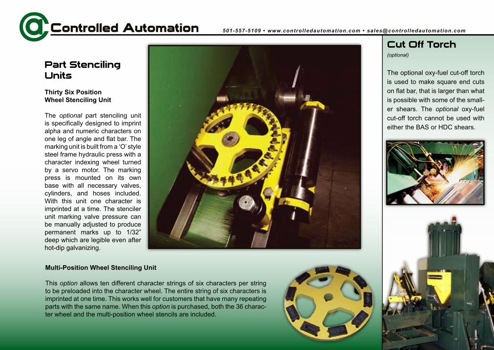
Cut Off Torch(optional)
The optional oxy-fuel cut-off torch is used to make square end cuts on flat bar, that is larger than what is possible with some of the small-er shears. The optional oxy-fuel cut-off torch cannot be used with either the BAS or HDC shears.
Multi-Position Wheel Stenciling Unit
This option allows ten different character strings of six characters per string to be preloaded into the character wheel. The entire string of six characters is imprinted at one time. This works well for customers that have many repeating parts with the same name. When this option is purchased, both the 36 charac-ter wheel and the multi-position wheel stencils are included.
Part Stenciling Units
Thirty Six Position Wheel Stenciling Unit
The optional part stenciling unit is specifically designed to imprint alpha and numeric characters on one leg of angle and flat bar. The marking unit is built from a ‘O’ style steel frame hydraulic press with a character indexing wheel turned by a servo motor. The marking press is mounted on its own base with all necessary valves, cylinders, and hoses included. With this unit one character is imprinted at a time. The stenciler unit marking valve pressure can be manually adjusted to produce permanent marks up to 1/32” deep which are legible even after hot-dip galvanizing.

501-557-5109 • www.controlledautomation.com • [email protected]
Storage And Loading Conveyor
The purpose of the Storage and Loading Conveyor is to stage angle and flat bar adjacent to the ABL-100 in-feed conveyor and to load this material onto the in-feed conveyor for processing. The loading conveyor is indexed by the operator as each piece is loaded. When the table is full the operator need only roll another piece onto the loading conveyor as a piece is processed through the machine. This system frees up the crane or lift trucks while the material is being processed. This also allows the loading conveyor to be staged with different material as the machine is running. Pneumatic let-down arms are located on the infeed conveyor, which gently lower the material into the infeed V-rolls. This reduces wear and tear on the machine. The addition of this optional feature greatly improves the production of the machine. A bundle of material can be placed on a customer supplied bundle rack (drawings supplied by Controlled Automation) and material rolled onto the loading conveyor.(Controlled Automation does not supply the bundle rack)
Hydraulic Power Unit
The hydraulic power unit is designed to supply flow only when needed. This keeps the hydraulic oil from heating, which reduces the chance of hydraulic system failure. The hydraulic power unit has all filters located for ease of maintenance. The unit is easily accessible, being on its’ own palletized base. A thermostatically controlled oil heater is provided to ensure proper function even in very cold shops.

501-557-5109 • www.controlledautomation.com • [email protected]
5’ Powered Out-Feed Conveyor and Work Surface
This is an optional 5’ long conveyor located on the out-feed side of the shear. It is powered. One side of its rolls can be lowered and used as a work surface by the operator. This conveyor, due to its close proximity to the operator, cannot be used as a dump conveyor.
5’ Non-Powered Out-Feed Conveyor and Work Surface
This optional 5’ long conveyor is the same as above, however the V-rolls are not powered. This option is only used when there are no powered conveyors used. When this option is chosen, the motor and drive chain can be added at a later time, for use with dump conveyors.
Powered Out-Feed and Dump Conveyor
This optional 15’ or 20’ conveyor is a “V-style” chain driven conveyor used to automatically or manually convey and dump the parts at drop locations. The conveyor automatically dumps parts into a drop location based on the part’s length. The computer senses the location of the part as it is moves down the conveyor by signals from photo eyes which are mounted down the length of the conveyor. When the part gets to the appropriate drop location the entire conveyor roller bed will pivot, dropping the material at the drop location. If a drop location becomes full a switch can be set so the next appropriate drop location can be used. The machine will continue to advance and punch the material as the dump conveyor is operating up to the point the advancing material interferes with the dump conveyor or the material needs to be sheared. Up to four dump conveyors can be tied together for an 80’ material discharge and dump out-feed. The dump conveyor is always used with the 5’ powered out-feed conveyor and work surface. In most circumstances the customer will build simple skid type racks to catch the material. This allows a chain to be wrapped around the material or access to the material by a fork truck.
10’ Non-Powered V-Roll Conveyors
This is an optional 10’ long conveyor is also located on the out-feed side of the shear. The V-rolls are also not powered with this option. This is another option which is only used when there are no powered conveyors used. The standard size on this out-feed option is 10’, however, custom lengths are available upon request.
(Powered dump conveyor and work surface and 15’ powered outfeed and dump conveyor shown)
(15’ powered outfeed and dump conveyor shown)
(5’ powered outfeed and work Surface shown)
(10’ non-powered outfeed conveyor)

ABL-100 Production SpecificationsMaterial positioning speed 0 TO 250 ft/minAccuracy +/- 1/32” mechanicallyPunch capacity 115 tons (143 ton optional)
Maximum hole size 1-3/8” with 115 ton tooling option 1-3/4” with 143 ton tooling option
Material SpecificationsMaximum length of material 40’ (for standard machine) 60’ optional
Minimum length of material 6’Maximum angle size 8” x 8” x 1”Maximum bar size 1” x 12”Minimum angle size 1-1/2” x 1-1/2” x 3/16”Minimum bar size 3/16” x 2-1/4”Channels (web punching only)
Maximum channel 12”Minimum channel 4”(when processing channel it cannot be cut with the shear. Channel must be pre-cut or cut by other means using the layout marks from the layout marking process.)
(All specifications are subject to change without notice)
Ten Position Wheel Stencil Character Depth Adjustable up to 1/32”Up to 6 character/positionCharacter height 3/8”
Hydraulic Power UnitElectric Motor 30 hp @ 1750 RPMLow pressure pump 20 GPM @ 2000 PSIHigh pressure pump 13 GPM @ 4500 PSIReservoir 90 gallonsThermostat/oil heater 110 volts
Stenciling Unit OptionsThirty Six Character Wheel Stencil36 CharactersCharacter height 3/8”Characters A thru Z Numbers 0 thru 9Character depth Adjustable up to 1/32”Max material thickness 1”
For more complete information on this or any of our ma-chines, contact our sales department at 501-557-5109 or
High flow HPU machine packages are available as an option.

© 2009 Controlled Automation, Inc. ABL100-09-0001
Controlled Automation specializes in the manufacture of automated structural steel drilling, punching, and shape cutting machinery. Material handling systems are also available to complement each type of machine we offer. As well as new
machinery, we are the industry leader in retrofitting control systems and remanufacturing existing structural steel fabricating machinery. All machines and controls are designed and manufactured entirely in the United States of America. All software is
developed in and supported from the United States of America.
501-557-5109 501-557-5618 Fax
US Mail PO Box 888
Bryant, AR 72089USA
Manufacturing facility 15701 West Sardis Road
Bauxite, AR 72011USA