angle measurement - beep.comsridharsdmit1.beep.com/apps/download?f=unit_3_angle_measurement.pdfangle...
TRANSCRIPT

Angle measurement 1. Introduction
2. Vernier bevel protector(universal bevel protector)
3. Optical bevel protector
4. Sine bar
Principle of sine bar
Accuracy of sine bar
Use of sine bar
Limitation of sine bar
5. Sources of errors in sine bars
6. Sine center
7. Angle gauges
8. Numerical problems on building of angles.
9. Clinometers.
Introduction:
Angle is defined as the opening between the two lines meet at a point.
If one line moved around a point in an arc, a complete circle can be formed.
The basic unit of angular measurement is the right angle, which is defined as the angle between two
lines which intersect so as to make the adjacent angle equal.
If a angle is divided into 360 parts, each part is called as degree (0)
Each degree is divided into 60 parts and each that part is called minute (‘).
Each second have 60 parts and each that part is called second (“).
An alternate method for defining the angle is based on the relationship between the radius and arc of
a circle.
The unit is called radian, and is defined as the angle subtended by an arc of a circle of length equal to
the radius as shown in figure.
When the radius OA = arc AB
The angle ϴ = 1 radian
In mathematical conversion, 2π = 360
1 radian = 360/(2π) = 57.29580
Instruments used for angular measurement. 1. Vernier bevel protector(universal bevel protector)
2. Optical bevel protector
3. Sine bar
4. Sine center
5. Clinometers

1. Vernier bevel protector (universal bevel protector): It is a simplest instrument used for measuring the angle between the two faces of a component.
As shown in figure, it consists of a base plate attached to the main body and an adjustable blade
attached, which in turn attached to a circular plate containing the Vernier scale.
The adjustable is capable of stretching freely along the groove provided on it and can be clamped at
any convenient length.
The adjustable blade along with circular plate containing the Vernier scale can rotate freely about the
center of the main scale engraved on the body of the instrument and can be locked at any desired
position with the help of clamping knob.
An acute angle attachment is given to measure the acute angle.
The base plate is made flat so that it can be laid flat upon the work and any type angle can be
measured(0 to 3600)
The main scale is graduated in degrees of arc.
The Vernier scale has 12 divisions on either side of the center zero line. They are marked o-60
minutes of arc. So that each division is 1/12 th
of 60 minutes = 5 minutes of arc.
These 12 divisions occupy 27 degrees of space on main scale. Each division Vernier is equal to
1/12 of 230 or 1 (11/12)
0
2. Optical bevel protector: A recent development of Vernier bevel protector is optical bevel protector.
In this instrument, a circular glass plate is divided at 10 minutes intervals throughout the whole 3600
are fitted inside the main body.
A small microscope is fitted through which the circular graduations can be viewed. The readings are
taken against a Vernier scale with the help of a microscope.
With the help of microscope it is possible to read about 2 minutes.

3. Sine Bar Sine bar are made from high carbon, high chromium, corrosion resistance steels which can be
hardened, ground and stabilized.
Two cylinders of equal diameter are attached at the ends as shown in figure.
The distance between the axes of the two cylinders will be 100,200, or 300 mm in metric system.
Depending on the accuracy of the center distance, sine bars are classified as A grade(accuracy upto
0.01 mm/m of length) and B grade (accuracy upto 0.02 mm/m of length).
Principles of sine bar:
The principle of operation of sine bar is relay upon the application of trigonometry.
The sine bar is basically designed for the precise setting out an angle in conjunction with the slip
gauges and surface plate.
By using above principle it is possible to set out any angle by using standards length of side AB and
marking the off the length of side BC equal to AB multiplied by the sine of the angle.
The sine bar is placed on the surface plate with the slip gauges of the required length (H) under one
roller and opposite to the angle ϴ as shown in figure,
The angle ϴ is given by,
ϴ = sin−1𝐻
𝐿
Accuracy requirements of a sine bar:
The axes over the roller must be parallel to each other and center distance is must be precisely known
The top surface of the sine bar must be flat and parallel to a plane containing the axes of rollers.
The rollers must be identical in diameter and round to within the close tolerance.
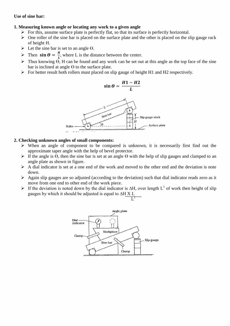
Use of sine bar:
1. Measuring known angle or locating any work to a given angle
For this, assume surface plate is perfectly flat, so that its surface is perfectly horizontal.
One roller of the sine bar is placed on the surface plate and the other is placed on the slip gauge rack
of height H.
Let the sine bar is set to an angle ϴ.
Then 𝐬𝐢𝐧𝜭 = 𝑯
𝑳, where L is the distance between the center.
Thus knowing ϴ, H can be found and any work can be set out at this angle as the top face of the sine
bar is inclined at angle ϴ to the surface plate.
For better result both rollers must placed on slip gauge of height H1 and H2 respectively.
𝐬𝐢𝐧𝜭 = 𝑯𝟏 −𝑯𝟐
𝑳
2. Checking unknown angles of small components:
When an angle of component to be compared is unknown, it is necessarily first find out the
approximate taper angle with the help of bevel protector.
If the angle is ϴ, then the sine bar is set at an angle ϴ with the help of slip gauges and clamped to an
angle plate as shown in figure.
A dial indicator is set at a one end of the work and moved to the other end and the deviation is note
down.
Again slip gauges are so adjusted (according to the deviation) such that dial indicator reads zero as it
move from one end to other end of the work piece.
If the deviation is noted down by the dial indicator is ∆H, over length L1 of work then height of slip
gauges by which it should be adjusted is equal to ∆H X L
L1

3. Checking of unknown angles of heavy component:
When components are heavy and cannot be mounted on the sine bar, the sine bar is mounted on the
component as shown in figure.
The height over the rollers can be measured by a Vernier height gauge using a dial gauge mounted
on the anvil of it.
Figure shows the use of height gauge for obtaining two readings over the two rollers of the sine bar.
The difference in the two readings of height gauge divided by the centre distance of sine bar gives
the sine angle of the component to be measured.
𝐬𝐢𝐧𝜭 = 𝑯𝟏 −𝑯𝟐
𝑳
Limitation of sine bars:
The accuracy of sine bars is limited by the measurement of center distance of two precision rollers.
Limitation in the use of sine bar as a primary standard of angle.
Measurements using sine principle are fairly reliable at angles less than 150
, but becomes
increasingly inaccurate as the angle increase.
The sine bar is inaccurate in measuring 450 because of following reasons;
The sine bar is physically clumsy to hold in position.
The body of the sine bar obstructs the gauge block stack, even if relived.
Slight errors if sine bar causes large angular errors.
Long gauges stacks are not nearly as accurate as shorter gauge blocks.
Source of errors in sine bar:
Errors in distance between the rollers
Errors in slip gauge combination used for angle setting.
Errors in parallelism between the gauging surfaces.
Errors in flatness of the upper surface of the bar.
Error in parallelism of roller axes with each other.
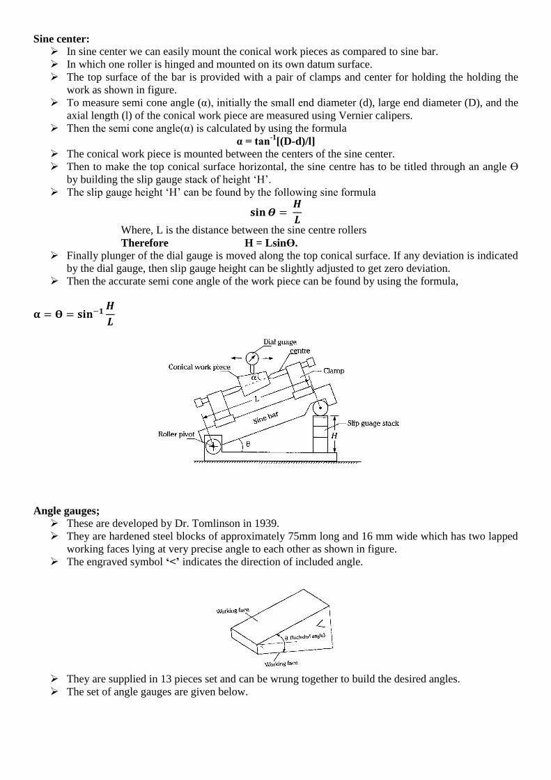
Sine center:
In sine center we can easily mount the conical work pieces as compared to sine bar.
In which one roller is hinged and mounted on its own datum surface.
The top surface of the bar is provided with a pair of clamps and center for holding the holding the
work as shown in figure.
To measure semi cone angle (α), initially the small end diameter (d), large end diameter (D), and the
axial length (l) of the conical work piece are measured using Vernier calipers.
Then the semi cone angle(α) is calculated by using the formula
α = tan-1
[(D-d)/l]
The conical work piece is mounted between the centers of the sine center.
Then to make the top conical surface horizontal, the sine centre has to be titled through an angle ϴ
by building the slip gauge stack of height ‘H’.
The slip gauge height ‘H’ can be found by the following sine formula
𝐬𝐢𝐧𝜭 = 𝑯
𝑳
Where, L is the distance between the sine centre rollers
Therefore H = Lsinϴ.
Finally plunger of the dial gauge is moved along the top conical surface. If any deviation is indicated
by the dial gauge, then slip gauge height can be slightly adjusted to get zero deviation.
Then the accurate semi cone angle of the work piece can be found by using the formula,
𝛂 = 𝚹 = 𝐬𝐢𝐧−𝟏𝑯
𝑳
Angle gauges;
These are developed by Dr. Tomlinson in 1939.
They are hardened steel blocks of approximately 75mm long and 16 mm wide which has two lapped
working faces lying at very precise angle to each other as shown in figure.
The engraved symbol ‘<’ indicates the direction of included angle.
They are supplied in 13 pieces set and can be wrung together to build the desired angles.
The set of angle gauges are given below.

These gauges together with a square block enable any angle between 0
0 and 360
0 to be constructed.
Each angle is a wedge, thus two gauges with their narrow ends together provide an angle which is
the sum of the angles of the individual gauges.
The engraved”<” in addition are all in the same direction as shown in figure.
Subtraction of angles are obtained when the narrow ends are opposed as shown in the figure, amd
engraved mark in opposite direction.
Numerical on building of gauges:

Clinometers:
Clinometer is a special case of the application of spirit level.
In which spirit level is mounted on a rotary member carried in housing.
The bottom end of the housing forms the base.
The angle of inclination of rotary members’ carries the spirit level relative to its base can be
measured by this circular scale.
The clinometer is mainly used to measure the included angle between two adjacent faces of the work
pieces.
In operation, clinometers is first placed on the face of the work piece as shown in figure.
Now rotary member is adjusted till the bubble is exactly at the center of the spirit level.
Then angle is noted down from the circular scale.
A second reading is taken in similar manner.
Now included is founded by using formula
γ =1800 – (α + β)