angra 1 npp full scope simulator development project … · angra 1 npp full scope simulator...
TRANSCRIPT

ANGRA 1 NPP FULL SCOPE SIMULATOR DEVELOPMENT
PROJECT
INTERNATIONAL ATLANTIC CONFERENCE - INAC 2015São Paulo, October 4 to 9, 2015ENINKnowledge Management and Personnel Qualification
E. Selvatici/L.C.C . Castanheira Eletrobrás Eletronuclear
J.A. Ruiz/F.J. Lopez Zazo Tecnatom

Angra 1 Nuclear Power Plant
• First Brazilian NPP, PWR 640 MWe
• NSSS supplier: Westinghouse; BOP:BechtelCorporation.
• Beginning of commercial operation: 1985
• Operator´s Simulator Training: simulators of similar Plants in the US and Spain
• Specific Angra 1 Full Scope Simulator: early objective of the Company– Steam Generator problems delayed objective;
– after SG replacement in 2009 and possibility of Plant lifeextension the simulator project was restarted andcompleted.

Why a Plant specific full scope simulator?
• Full-scope simulators are recognized worldwide as the only realistic method to provide real time and hands-on training of operators to correctly respond to, and mitigate potential accidents
• Licensing authorities requirements on simulator training
• Fidelity to the Plant Control Room can only partially be attained when training in a similar Plant simulator
• Valuable tool to support development and validation of operating procedures and verification of Plant modifications.

Scope of a simulator project development
• ANSI/ANS 3.5, Nuclear Power Plant Simulators for Use in Operator Training and Examination, is the internationally adopted standard for Nuclear Power plant simulator development
• This standard establishes – the functional requirements for full-scope nuclear
power plant control room simulators;– The criteria for the scope of simulation, performance,
and functional capabilities.
• The 2009 version of this standard at was adopted for the development of the Angra 1 simulator (most recent version at the start of the project)

Summary of ANSI/ANS most important requirements
• Physical fidelity and human factors– Scope of panel simulation
• panels, consoles, and operating stations that are simulated replicate the size, shape, color, and configuration of those of the reference unit.
– Instrumentation, controls, markings, and operator aids• instrumentation, controls, markings, and operator aids that are on panels,
consoles, and operating stations, replicate the size, shape, color, configuration, feel, and dynamic functioning of those of the reference unit.
– Control room environment• simulator control room environment replicates the reference unit control
room
• Systems to be simulated and the degree of completeness– Systems controlled or monitored from the control room
• the systems of the reference unit that are within the scope of simulation are adequate to perform the normal evolutions and the malfunctions.
– Systems controlled or monitored external to the control room• Systems operated or monitored external to the control room, and necessary to
perform the normal evolutions and the malfunctions are simulated

The Angra 1 Full Scope Simulator Project Time Schedule

Main activities of the project
• Preparatory activities– preparation of a detailed simulator specification;– establishment of the Eletronuclear´s team for project support and
follow up;– international bid for contracting of an experienced simulator
supplier. Bid won by the Spanish company TECNATOM, supplier of
simulators and operators training for NPP in Spain and abroad.
• Main development activities – agreement between Eletronuclear and the Tecnatom on a
detailed activities time schedule, means of communication, Eletronuclear´s participation in the different phases of the project;
– identification, collection and transfer to Tecnatom of the required Plant documentation;
– preparation by Tecnatom and review by ETN of the system design documentation;

Main activities of the project• Main development activities (cont.)
– Tecnatom´s provision (acquisition or manufacturing) of the simulator control room hardware;
– Tecnatom´s development of the software (plant model);– integration by Tecnatom of the hardware and software and
performance of pre-factory tests, with ETN participation;– performance of factory tests (Factory Acceptance Tests (FAT):
comprehensive tests at the supplier) by Tecnatom with ETN participation;
– acceptance by ETN after successful completion of the FAT;– packing and shipping of the simulator to the Mambucaba
Training center;– installation of the simulator in the new building erected in
parallel with the simulator development at the supplier;– performance of the SAT (Site Acceptance tests);– demonstration of availability/reliability through two month of
continued operation;– Delivery of the final simulator documentation.

Angra 1 FSS Technical Specification requirementsGeneral Requirements• The FSS has be installed in ELETROBRAS ELETRONUCLEAR Training
Center at Mambucaba, Paraty, Rio de Janeiro, Brazil.• New Training Center facility to be built for the Angra 1 FSS.• The Full Scope Simulator consists of six definable hardware
elements:– the simulated control room;– the two remote shutdown panel rooms;– the local control stations room;– the FSS instructor station;– the computer complex (including peripherals and linkages) and the
software necessary to simulate the physical reference unit processes, including control and support software, and
– the Process Information System.
• ANGRA 1 FSS simulator design is based on the Angra 1 NPP reference documents– Plant data freeze date established to be 30/09/12;– Tecnatom was responsible for the suitability and coherence of data used;– A communication mechanism to ask for further necessary information was
established.
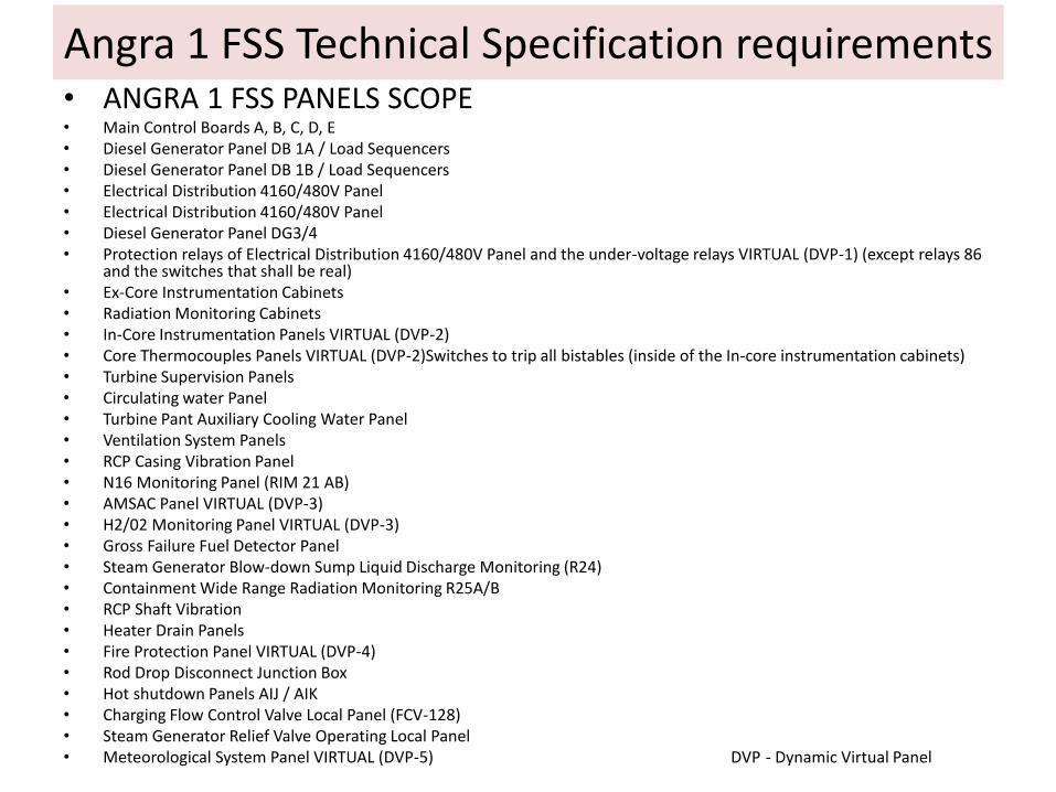
• ANGRA 1 FSS PANELS SCOPE• Main Control Boards A, B, C, D, E• Diesel Generator Panel DB 1A / Load Sequencers• Diesel Generator Panel DB 1B / Load Sequencers• Electrical Distribution 4160/480V Panel• Electrical Distribution 4160/480V Panel• Diesel Generator Panel DG3/4• Protection relays of Electrical Distribution 4160/480V Panel and the under-voltage relays VIRTUAL (DVP-1) (except relays 86
and the switches that shall be real)• Ex-Core Instrumentation Cabinets• Radiation Monitoring Cabinets• In-Core Instrumentation Panels VIRTUAL (DVP-2)• Core Thermocouples Panels VIRTUAL (DVP-2)Switches to trip all bistables (inside of the In-core instrumentation cabinets)• Turbine Supervision Panels• Circulating water Panel• Turbine Pant Auxiliary Cooling Water Panel• Ventilation System Panels• RCP Casing Vibration Panel• N16 Monitoring Panel (RIM 21 AB)• AMSAC Panel VIRTUAL (DVP-3)• H2/02 Monitoring Panel VIRTUAL (DVP-3)• Gross Failure Fuel Detector Panel• Steam Generator Blow-down Sump Liquid Discharge Monitoring (R24)• Containment Wide Range Radiation Monitoring R25A/B• RCP Shaft Vibration• Heater Drain Panels• Fire Protection Panel VIRTUAL (DVP-4)• Rod Drop Disconnect Junction Box• Hot shutdown Panels AIJ / AIK• Charging Flow Control Valve Local Panel (FCV-128)• Steam Generator Relief Valve Operating Local Panel• Meteorological System Panel VIRTUAL (DVP-5) DVP - Dynamic Virtual Panel
Angra 1 FSS Technical Specification requirements

Angra 1 FSS Technical Specification requirements• Angra 1 NPP Main Control Room Lay out (to be replicated in the FSS control Room)

Concept and Tools

OVERVIEW OF THE ANGRA 1 FULL SCOPE SIMULATOR CONCEPT
TH systems
Neutronics
Electrical systems
Logic & Control
Instructor Station Server
Interface I/O
PANELS & INSTRUMENTATION(switches, alarms, lights, controllers, horns, …)
Simulator server
Training Aids
Instructor Station
Simulation management
PANELS & INSTRUMENTATIONOperation computers (SICA, OVATION, WDPF, virtual instrumentation, …)
Electr. signals
Comm. system
Comm. system
Comm. system

CMS/TecSIM
TRAC_RT, TEAM_FLOWTEAM_LOGIC
NESTLE
TEAM_ELECTRIC
TEAM_LOGIC
Instructor Station Server
TESIS+
PANELS & INSTRUMENTATIONReplica when available, similar or simulated if not available
Simulator server
TEAM_SKETCHTEAM_DESICOMOTO
TEAM_STATION
TEAM_K
Operational windowsSICA - estimulatedOVATION-WDPF –Team_SketchVirtual instrumentation -TEAM_SKETCH photo realistic
0-10 volts
Web services
Web servicesGiga ethernet
TR/IN/RG
OVERVIEW OF THE TECNATOM TECHNOLOGICAL TOOLS APPLIED TO THE ANGRA 1 FSS

Hardware Development

FSS Control Room Data Acquisition Survey
• A complete photogrammetric reportage of the Angra 1 Control Room was used in the design process.
• Data acquisition survey carried out by Tecnatom during 2 weeks:– Specific mechanical parts
– Panels dimensions checking
– Specific instruments data
– Obsolete instruments sample
– RAL color notes for panels and faceplates

FSS Control Room Data Acquisition Survey
• Assigning labels to elements

NPP Hardware Design Documents- FSS Control Room Input Data-
FIRST VOLUMETRIC AND SHEET METAL APPROACH
Different distribution and measures that technical specification

NPP Hardware Design Documents- FSS Control Room Input Data-
• Detailed information about instruments:– Manufacturer
– Models
– Engraving texts
– Scales
– Etc.

Preliminary FSS Hardware Design Specification
• Hardware Documents describing panels:
– Number of panels: 30
– Units and modules
– Real or Virtual panel
– Nomenclature
• Instrumentation description:
– Families and units
– Manufacturers and models
– Signals number

FSS Hardware Design Documentation
– MECHANICAL DESIGN• PANELS
• PANELS BENCHES

FSS Hardware Design Documentation
– PAINTING DESIGN. RAL Code "Reichsausschuß für Lieferbedingungen und Gütesicherung“

FSS Hardware Design Documentation
– SIGNALS DISTRIBUTION. INTERFACE SYSTEM
– INSTRUMENTATION
– CLASSROOM SIMULATOR

FSS Hardware Design Documentation
• TESIS+ : Very simple system layout

FSS Construction and Temporary assembling
• CONSTRUCTION IN TWO PHASES:– MAIN CONTROL BOARD A, B, C, D, E, DIESEL 1&2 AND ELECTRICAL PANELS
– REST OF PANELS

FSS Construction and Temporary assembling
– TEMPORARY ASSEMBLING IN TECNATOM FACILITIES• TRANSPORTATION MODULES. NOT SIGNALS REMOVING.
– SIGNALS TESTS AND PHYSICAL FIDELITY TESTS

FSS Hardware Tests
– ELECTRICAL TESTS
– DATA ACQUISITION INSTALLING AND SIGNAL TESTS
– PHYSICAL FIDELITY TESTS
– PANELS AND STRUCTURE VERIFICATION
– COMMUNICATION TEST. TESIS+
– VERIFICATION OF I/O SPARES
– STANDARDS COMPLIANCE VERIFICATION
– CONTINUOUS OPERATION TEST
– TESIS+ CUSTOMIZED TESTS
– HARDWARE DOCUMENTATION VERIFICATION
– HARDWARE SWITCHING ON MANUAL

Software Development

ANGRA 1 FSS SYSTEMS TECHNICAL SPECIFICATION SOFTWARE REQUIREMENTS
LEVELS OF SIMULATION FIDELITY Full Simulation (FS) :High fidelity simulation based on first principles achieved by the application of conservation laws of mass, energy and momentum, other physical laws of mechanics, thermodynamics, recognized engineering correlations . Replication of the system topology is done with very minimum simplifications.Simplified Dynamic Replica (SM): Simplified dynamic replica is also based on first principles. The replication of the system topology is simplified. In addition, lumping of redundant equipments is made if no specific malfunctions are specified on them. Functional Replica (FN): Functional simulation is partly based on first principles and inductive modeling in which inputs-outputs behavior of the system are modeled to reproduce observed behavior. The replication of the system topology only considers the devices which are necessary to replicate the basic function of the system (interlocks to simulated system, flow/heat source to simulated system, etc).
ANGRA 1 SYSTEMS SIMULATION SCOPE• Of the 83 Angra 1 systems scope of simulation,
• a full simulation (FS) was performed for 70, • a simplified dynamic replica (SM) was used for 7 and • a functional replica (FN) for 6 systems.
• Systems simulated using SM or FN level, are systems that have little or no impact in the Plant transient behavior .

Angra 1 FSS System simulation documentation
• Modeling Techniques Handbook (MTH)
– Sets up tools and techniques to be used for developing
• Nomenclature Symbol Dictionary (NSD)
– Nomenclature to be used on development
– Organize models related to systems

Angra 1 FSS System simulation documentation
• Input for the Plant systems modelling
– Angra 1 Plant system data (system descriptions, component data sheets, E and I&C diagrams, etc);
– Development by Tecnatom of preliminary system design specifications (PSDS) for the scope of 83 Plant systems to be simulated;
• definition of the scope and level of simulation (full or partial), as well as the system´s data needed for the simulation.
– Review and release of the PSDS by ETN for Plant modelling work.

Tecnatom software used for Plant system modeling
• The set of codes used by Tecnatom for Plant system simulation consisted of:
– proven industry codes for simulation of core behavior and core and Primary system thermalhydraulics, TRAC_RT and NESTLE_RT, adapted for real time calculations;
– plus a set of computational tools developed for simulation of hydraulic, electric and control networks, TEAMFLOW, TEAMELECTRIC and TEAMLOGIC;
– plus auxiliary computational tools (TEAM_AIDES) for different purposes.

Ref.Cod.: PRe-SANGRA-01 33
TECHNOLOGICAL APROACH
MODELLING
TOOLS
BOP + AUXILIARIES
TEAM MODEL BUILDER
HYDRAULIC NETWORKS
THERMALHYDRAULIC
CONFIGURATION MANAGEMENT SYSTEM
SIMULATION ENVIROMENT
SIMULATION
TECHNOLOGY
INSTRUCTOR
STATION
INSTRUCTOR STATIONMODELLING
TOOLS
NSSS
CODESINPUT - OUTPUT
NEUTRONIC
ELECTRICAL NETWORKS
CONVENTIONAL
MODELS
LOGIC & CONTROL
CLASS ROOM
TRAINER
TEAM SKETCH
T_CCS
NESTLE

TRAC_RT : REAL TIME THERMALHYDRAULIC BEST ESTIMATE SIMULATION CODE
TRAC_RT (Transient Reactor Analysis Code - Real Time)
is an advanced version of TRAC “best-estimate” thermalhydraulic code
series for simulation of trasients in Light Water Reactors (LWR),
adapted by TECNATOM for being implemented into NPP training and
engineering simulators.

1. Improvements for computational efficiency
• Fully implicit solution of mass and energy equations
• Removal of discontinuities in equations and correlations
• Replacement of algebraic equations for properties and
constitutive correlations by table lookup
• Optimization of data structure and management
• Implementation of a selective iteration technique
• Increase of the allowed input model size (FA matrix
dimension)
• External access allowed to any simulation variable
(interactivity)
• Interactive debugger may be used with the code in real
time
TRAC_RT : Advanced version of TRAC code series adapted by TECNATOM for simulation purposes …

2. Additional or modified models to fulfill simulation
requirements
• Enlargement of the steam tables scope
• Capability to couple the FUEL ELEMENTS and 3D VESSEL components to
advanced 3-D neutronic codes
• Fuel rod failure and fission product release modelode
• Pump driving electrical motor model
• Pump cavitation model
• Modified pump friction torque treatment
• Externally controlled junction flow area (valve)
• Externally controlled mass/energy makeup to any 1-D cell
• ......
TRAC_RT : Advanced version of TRAC code series adapted by TECNATOM for simulation purposes …

TRAC_RT / NESTLE_RT coupling scheme
REACTIVITY
POWER GENERATION
RATE
Neutron poison
build-up
Xe / Sm
cross-sections
Control
rods
Doppler (fuel temp) cross-sections
Moderator density
cross-sections
Soluble poison
cross-sections
Energy deposition in fuel
Fuel temperature
Heat removal from fuel
Heat deposition in coolant
Coolant temp/density
Boron concentration
in coolant
TRAC_RTThermalhydraulic model
NESTLE_RTNeutron kinetic model
NEUTRON FLUX
Flo
w r
ate
th
rou
gh
co
re

TF main charateristics are:• Simulation model generation from graphic sheets.• Code generation associated to these sheets.• Insertion of the code into the simulation environment, including
the DB administration.• Connection with the simulation environment, variable display,
modifications, RUN/FRZ, initial conditions…
TeamFlow (TF). Belongs to TEAMSUITE environment
Tool designed to realice the hydraulic system calculations at a real timesimulation.
The hydraulic net solution consists on the calculation of the temperatureand pressure fluid and the mass flow in all the hydraulic circuit elements.
TEAM_FLOW

TEAM_ELECTRIC
TE main charateristics are:• Simulation model generation from graphic sheets.• Code generation associated to these sheets.• Insertion of the code into the simulation environment, including
the DB administration.• Connection with the simulation environment, variable
display,modifications, RUN/FRZ, initial conditions…
TeamElectric (TE): Belongs to TEAMSUITE environment.
Tool designed for electric system calculation in a real time simulation.
The electric net solution consists on the calculation of the currents andvoltages of the net and active, reactive and apparent power.

TeamLogic (TL). Tool designed to model logical and control systems
calculations at a real time simulation.
TEAM_LOGIC lets the user model any type of diagram (explicit dynamic,logic, control or cabling). The modeled diagrams are built using the iconsassociated to each reference diagram symbol, making the connectionsbetween them and introducing the specific data in the corresponding icons.
TL is valid also for every calculation where an explicit scheme for calculate the solution is valid.
TEAM_LOGIC

TEAM_EDITOR_Course
TeamEditor. Tool designed to build-up new icons and libraries creating
the new icon and its associated code.
This allows the user to incorporate any plant component
Team Editor is executed from Team Logic, selecting the “ICON” option andthen “EDITOR” from the TEAM LOGIC bar.

Auxiliary software (TEAM_AIDES)- Team_K: Responsible to control the simulator server execution SETRU / URTES ways of working.
- TESIS+: Input / Output Interface designed by Tecnatom to interconnect any simulation software and the associated instruments. TEcnatom System Interface for Simulators.
- TEAM_STATION: application designed to provide instructors with the ability to control and supervise simulation sessions. TEAM_STATION has been developed using the Microsoft Visual Studio C#, object-oriented language for the Microsoft .NET platform.
- TEAM_SKETCH is the Tecnatom solution to design and create dynamic and interactive Human Machine Interfaces in simulation applications. In Angra I FSS simulator has been used to develop:
– OVATION operational windows
– Virtual panels
– Class room simulator
– Dynamical and interactive Instructor Station PIDs
- TEAM_DESI: Tool used by developers to built, validate, adjust and develop specific tools (COMOTO) simulation models.
- COMOTO: tool designed to allow a fast and easy comparison between current simulator state and Plant core physics calculation code (ANC) reference data, in terms of neutron flux, both fast and thermal, and in terms of thermal power as well.
- CMS/TecSIM: Control and administration of all information about the configuration of the simulator, checking of data, to document, test and develop programs using the information of the CMS database, and as a common interface to data entry. Once the information is in the CMS other modules of the simulator can use it.

43
Red LAN
Microsoft SQL ServerAccess security
Multiple users
Data integrity
Microsoft Access ClientsUser friendly
Different queries and interface
Ref.Cod.: PRe-SANGRA-01
Configuration Management System

Integration Hardware Software
• The Systems models, developed using the described Tecnatom software were tested, one by one and coupled together, composing the full Plant simulation model;
• The full Plant simulation model was integrated with the FSS Control Room and Hot Shutdown panels using the Tecnatom TESIS+ Input/Output interface (work done in Spain, at the Tecnatom facilities in Madrid);
• An extensive testing phase (pre-FAT and FAT) was
performed. (FAT: Factory Acceptance Tests).

Pre-FAT and FAT• Pre-FAT phase (Pre Factory Aceptance Tests): start of the process of
elimination of discrepancies of hardware (instrumentation, buttons, actuators, etc.), and afterwards discrepancies of the combined hardware/software operation.– This phase lasted 4 month, and was performed at Tecnatom with participation
of an ETN software/hardware engineer from the Training Center.
• After conclusion of the Pre-FAT, the FAT (Factory Acceptance Tests) was started. In this phase all the Acceptance Test Procedures (ATP) were performed being 11 Hardware ATP, 7 Software ATP and 17 Operational ATP. Two senior operators from ETN took part.– These 35 Acceptance Test Procedures, had sub-tests, for example, Systems
Tests had 350.
– More than 100 plant procedures have been tested, resulting in more than 1.500 hours of Simulator tests and more than 14,000 pages of testing results.
• This Testing Phase at the Factory (Supplier) was concluded after acceptance by ETN with the demonstration of an adequate performance of the FSS with only minor discrepancies remaining.

Disassembling and Transportation
– Disassembling in transportation modules• Sea Transport. 4 x Open Top HIGH CUBE 40’ Containers & 1 x 20’ Dray Van
• Sea Packages for preserving humidity and blows.
• Packing list inventory including 115 boxes of auxiliary material and spare parts.

Simulator Building construction• In parallel to the simulator development the simulator
building at the ETN Training Center in the Mambucaba village was constructed.– with project and construction under ETN responsibility.
– concrete modular construction was used.
– construction was completed in 6 month.

Definitive assembling at Mambucaba
– Tecnatom and subsidiaries carried out the following tasks in MambucabaFacilities.
• Packing checklist and travel damages checklist
• Boxes unloading with a crane
• Boxes opening
• Panels benches placement and leveling
• Panels benches drilling and fixing
• Panels movement an placing with a forklift
• Panels mechanical assembling
• Cables trays placement
• Electrical wiring
• Signals and communication wiring
• Electrical Tests
• Signals Tests
• Video camera installing
• Sound system installing
• SITE ACCEPTANCE TESTS

Site Tests• The packages containing the simulator arrived at the ETN Training
Center in mid June 2014 and at end of August the installation in the new building was completed.
• Site Acceptance tests (SAT) phase was performed from August , to mid November, 2014. For this purpose the FAT tests were repeated. This phase is required to:– verify if disassembling, transportation and reassembling did not introduce any
malfunctioning of the simulator.
– as an opportunity to eliminate most of the remaining minor discrepancies.
• The final project activity, “Demonstration of the Availability and Reliability of the FSS” , consisting of:– the continuous operation of the simulator 18 hours/day for two month
– with a down time less than 2%
was completed successfully by end of February 2015.

CONCLUSIONS• The acquisition of a specific full scope simulator is a large project that involves
substantial financial resources and requires specialized human resources also on the Costumer side.
• The Angra 1 simulator project was a successful one, being developed on time and cost by the supplier Tecnatom, meeting all the steps of the contract time schedule.
• From the Customer side, specialists on plant equipment, plant procedures and operation and core/reload calculation details have to be available to support the simulator Supplier on Plant specific details and follow up of tests.
• Identification and gathering of the large required amount of updated Plant documentation to be provided to the Supplier is a very time consuming task and depending on the type of information may require authorization from other parties.
• It is a general opinion at ETN that the Angra 1 Full Scope Simulator supplied by Tecnatom, is a high quality training installation that will certainly take the Angra 1 operators operational and safety performance to a new level.
• Use of the Angra 1 full scope specific simulator, available on site, will allow the operators to train in a control room environment identical to that of the Plant, actuating on identical instruments and viewing data from identical instrumentation, bringing among other, more training flexibility and training time, possibility of replication of transients occurring at the Plant for assessment of Plant response, testing in advance Plant and operational procedure modifications.

View of the Control Rooms of the Angra 1 Plant and of the completed Angra 1 FSS.
CAN YOU TELL WHICH IS WHICH?