anhydrite/aerogel composites for thermal insulation - · pdf fileanhydrite/aerogel composites...
TRANSCRIPT

ORIGINAL ARTICLE
Anhydrite/aerogel composites for thermal insulation
D. Sanz-Pont . D. Sanz-Arauz .
C. Bedoya-Frutos . R. J. Flatt . S. Lopez-Andres
Received: 8 August 2015 /Accepted: 13 November 2015 / Published online: 19 November 2015
� RILEM 2015
Abstract High performance thermal insulating
composite materials can be produced with mineral
binders and hydrophobic aerogel particles through a
hydrophilization process for the latter with surfac-
tants. The present study is focused on the development
of aerogel/calcium sulfate composites by the hydro-
philization of hydrophobic silica aerogel particles
through a polymer-based surfactant. Its effects on the
microstructure and hydration degree are examined as
well as their relation to the resulting mechanical and
physical properties. Results show that composites
with an around 60 % of aerogel by volume can
achieve a thermal conductivity\30 mW/m 9 K.
Interestingly, a surfactant addition of 0.1 % by wt%
of the water in the mixtures provides better material
properties compared to a surfactant wt% addition of
5 %. However, it has been found around 40 %
entrained air, affecting the material properties by
reducing the binder and aerogel volume fractions
within the composites. Moreover, gypsum crystal-
lization starts to be inhibited at aerogel volume
fractions[35 %. Towards material optimization, a
model for the calculation of thermal conductivity of
composites and an equation for the compressive
strength are proposed.
Keywords Aerogel � Surfactant � Anhydrite �Composite � SEM � Thermal insulation
1 Introduction
The high energy consumption of old buildings is often
related to a lack of thermal insulation of the building
enclosure [60, 65]. For masonry based buildings,
energy saving targets can be met with thermal
insulating panels with a suitable hygrothermal behav-
ior [38]. However, such constructive systems require
flat surfaces, panel adjustments, gluing and so forth. In
contrast, mortars with high thermal insulating proper-
ties, besides not presenting the paneling systems
disadvantages, can fill gaps and provide a continuous
thermal insulating layer avoiding thermal bridges.
Their thermal conductivities are however not as low.
Nevertheless, enhancements of the thermal insulating
properties of mortars can be achieved by using aerogel
particles as lightweight thermal insulating aggregates,
D. Sanz-Pont (&) � D. Sanz-Arauz � C. Bedoya-FrutosDepartment of Construction and Architectural
Technology, Polytechnic University of Madrid, Madrid,
Spain
e-mail: [email protected]
D. Sanz-Pont � R. J. FlattDepartment of Civil, Environmental and Geomatic
Engineering, Institute for Building Materials, ETH
Zurich, Zurich, Switzerland
S. Lopez-Andres
Department of Crystallography and Mineralogy,
Complutense University of Madrid, Madrid, Spain
Materials and Structures (2016) 49:3647–3661
DOI 10.1617/s11527-015-0746-8

taking advantage of the very low thermal conductivity
generated by their nanoporous structure [8, 14, 35].
There has been a rising interest in aerogels for
building applications in the last years, mainly for
building insulation [4, 7, 27, 30, 37, 39, 50, 55, 66, 76].
Aerogel granules have become more popular than
monolithic aerogels due to lower production costs.
Lately, a rising use of aerogel granules has been
reported as thermal insulating aggregates in composite
materials, based on mineral binders [10, 18, 24, 25, 36,
45, 58, 64]. The resulting composites can be used in
buildings as renderings or as thermal insulating layers;
however, these composite materials typically present
low mechanical strength, especially if the target is to
achieve high insulating values, as can be observed
from [3], with a compressive strength around
0.08 MPa and a thermal conductivity of 34 mW/m
9 K. Because of this behavior, external rendering
applications of these products typically require addi-
tional mesh reinforcement and an external protective
layer. However, it would be of great interest to be able
to reduce or eliminate the need of a mesh reinforce-
ment, by reaching a compressive strength[0.40 MPa,
so it can comply with the first category (CS I) of the
European Standard 998-1, regarding thermally insu-
lating mortars for exterior applications.
Hydrophobic aerogels are mostly used in building
applications. This type of aerogels have undergone a
surface modification, which provides the hydrophobic
character [32, 41, 43, 54, 61, 63, 68, 69, 72, 74]. In
particular, their contact angle with water droplet
depends on the silylating agent (non-polar groups)
[43, 54, 61, 69]. The data regarding water absorption of
such aerogels shows that the untreated aerogels (hy-
drophilic) absorb water by 4–5 times their own weight,
while silylated aerogels (hydrophobic), absorb less than
2 % water with respect to their own weight [68].
Nevertheless, the high hydrophobicity of aerogels poses
a processing problem when mixed with water based
mineral binders. This can be overcome by hydrophiliz-
ing the aerogels with surfactants or by adding wetting
additives to form a hydrophilic coating around the
hydrophobic core of the aerogel particles [18].
Surfactants are amphiphilic compounds that com-
prise a hydrophilic head and a hydrophobic tail. They are
mostly used in the manufacture of detergents, soaps and
many other personal care products. In building applica-
tions, surfactants have been used recently to form
mineral slurries with hydrophobic aerogel particles [10,
18, 36], besides other uses, like air-entraining agent to
produce freeze–thaw resistant concrete, but also foamed
concrete [19, 46, 49, 70, 73]. However, their use in
cement-free based composites has received compara-
tively little attention. One of the objectives of this paper
is to remedy this situation because of the promising
perspectives offered by such systems as high perfor-
mance insulating renders. In particular, we examine how
the binder matrix hydration and microstructure is
affected by the presence of polymeric surfactants and
a high concentration of hydrophobic aerogel particles.
This sets the basis for a rational discussion of the
development of physical and mechanical properties in
these novel mineral based composites.
Besides a good thermal insulation, the rehabilita-
tion of old buildings based in historic masonry
requires a material compatibility between the repair
mortars and the pre-existent main facade material
[34], which is why binders compatible with historic
mortars should be preferred. From this perspective, it
is worth noting that although hemihydrate has been
broadly used for developing building composites [13,
17, 22, 26, 31, 42, 48, 67, 75], only anhydrite based
binders are considered as repair mortars for exterior
applications by RILEM TC203RH [34]. Although
allegedly not water resistant, anhydrite based mortars
have been successfully used for exterior renderings [2,
40, 52, 56, 57] and joints in exterior walls of historic
buildings [44]. They appear to present better water
resistance and mechanical properties than correspond-
ing binders prepared with hemihydrate, probably
because they can be prepared with lower water/binder
ratios, producing lower porosities and higher densities
in the hardened material. Thus, gypsum based on high
anhydrite content and low water/binder ratios can be
considered for exterior applications.
The main aim of the present paper is therefore to
study the preparation and material properties of
thermally insulating renders based on anhydrite binder
and aerogel particles. More specifically, we develop
our approach by studying the resulting density of the
binder matrix and volume content of the components
within the composites providing key information
about this type of mixtures not reported in other
studies before. For this, we first compatibilize the
hydrophobic silica aerogel particles with the selected
water-based mineral binders by a hydrophilization
process through a polyethylene-glycol – polypropy-
lene-glycol – polyethylene-glycol block copolymer
3648 Materials and Structures (2016) 49:3647–3661

(PEG-PPG-PEG) based surfactant, then, we study the
effect of the surface modification of aerogels by
measuring the water absorption capacity during the
preparation of the samples, and finally, the resulting
microstructure of the composites, the binder hydra-
tion, as well as the mechanical, thermal and physical
properties. The surfactant used is specifically non-
ionic, to avoid possible ionic interactions with the
mineral binder.
2 Experimental
2.1 Materials
The composites were produced through the mixture of
the following materials, in different ratios:
(1) Anhydrite II (artificial) from CTH Navarra, for
the main mineral binder [6], obtained by calci-
nation of natural gypsum between 300 and
700 �C (particles:[0.8 mm—2 %,[0.2 mm—
30 %).ClassifiedTypeA (according toEuropean
Standard [21]).
(2) Hydrophobic silica aerogel granules
(0.01–1.2 mm) from Cabot, as insulating aggre-
gates [12]. Thermal conductivity (k) of
0.013 W/m 9 K at 21 �C, porosity[90 %,
particle density (120–180 kg/m3), oil absorp-
tion capacity (5.4–6.5 g/aerogel g).
(3) Non-ionic liquid surfactant (PEG-PPG-PEG) from
BASF [53], for the hydrophilization of the aerogel
particles. Molar mass of 3650 g/mol, density of
1.03 g/cm3, surface tension of 35 mN/m.
(4) Distilled water at 21 �C, for the formation of the
gypsum composites slurries.
Table 1 shows the real density of the base materials
measured by helium pycnometer and the particle
density of the aerogel particles as reported earlier [47].
2.2 Mixtures
2.2.1 Surfactant treatment
In order to reduce the hydrophobic forces of the
hydrophobic aerogels, and compatibilize them with
water, two different surfactant dosages (0.1 and 5 %
weight of the solution) were tested within the
composite mixtures, measuring the water absorption
capabilities of the aerogels after the re-treatment for
each case.
2.2.2 Sample preparation
The composition of all samples is described in
Table 2. The series are divided in two families; A
and B. The main difference between both is related to
the surfactant amount. The A and Bmixtures contain a
constant addition of 0.1 and 5.0 % of surfactant
respectively in relation to water. The 5 % stands for
the concentration typically used to stabilize air
bubbles in foamed concrete [70]. The 0.1 % was the
lowest concentration we found to be able to stabilize
aerogel particles in all the aerogel concentrations, of
the A series. Also, each family is further divided into
series with different additions of aerogel particles by
wt% of the mineral binder (0, 10, 20, 30 and 100 %).
Samples were prepared following the manual
procedure described in the European Standard [21]
using a rubber spatula (5.1 9 7.9 cm, total length
24.2 cm), with minor changes. First, the addition of
the surfactant to the distilled water; second, the
addition of the anhydrite followed by a first 30 s
manual stir; and third, the addition of the aerogel
granules followed by another 30 s manual stir, both
describing 30 movements (one per second) in form of
number eight. This ‘‘gently’’ manual stirring proce-
dure prevents the aerogel particles from crushing, as
could be expected by using a more intense or
mechanical mixing process. In addition, this modified
procedure allows the anhydrite to hydrate partially
before adding the aerogel granules and was found to
lead to a better dispersion.
The final slurries are poured into standard molds
(4 9 4 9 16 cm, 3 specimens in two groups), and two
11 9 5 9 2 cm specimens for the thermal conductiv-
ity test, for each mixture series. Table 2 also shows the
water/binder ratios used in the preparation of the
specimens, all having the same flowability (160 mm)
Table 1 Real density of the base materials
Mineral
binder
Aerogel
particles
Surfactant
Real density (g cm-3) 2.732 1.845 1.03*
Particle density (g cm-3) – 0.155** –
Calculated porosity (%) – 91.6 –
* From technical datasheet, ** [45]
Materials and Structures (2016) 49:3647–3661 3649
according to the European Standard [21] (this also led
to measure the water absorption capacity of the re-
treated aerogels during sample preparation). Labora-
tory conditions: 21 �C and 50 % RH.
2.3 Sample testing methods
2.3.1 Physical and mechanical properties
Physical and mechanical tests were made by the
procedure described in the European Standard [21],
cured at 21 �C and 50 % RH for 7 days and then dried
up to constant weight at 45 �C. The apparent porosity% (water accessible porosity), was determined by the
Archimedes method, by the immersion of the samples
in water at RT for 24 h. The water absorption tests
were made by the procedure described in the European
Standard [20]. For thermal conductivity, a FP2C
Neotim (ASTM 5930-97 standard), with the ‘‘Hot
wire’’ method described in RILEM [1], with a
measurement range between 0.02 and 5 W/m�K. Inthis test, specific probe is sandwiched between two
plates of the material to be measured, so that the
thermal response is an average between the properties
of both plates. For real density of the base materials, a
Helium Pycnometer Micrometrics AccuPyc II 1340.
2.3.2 Mineralogical and microstructure
characterization
For X-Ray diffraction analysis, a Bruker D8
Advance diffractometer, working in Bragg-Bentano
geometry, provided with an X-ray source with a
high stable copper anode and an energy dispersive
detector SOL-X has been used. The experimental
conditions were: measurement range 2–508 2h with
time step-scanned of 1 s, fixed-angle divergence slit
of 0.02� 2h. The software used was EVA
DIFFRACplus. The semi quantitative analysis of
the crystalline phases was done by the Chung
method [15, 16], set by the three most intense (hkl)
crystallographic plane directions for the more rep-
resentative components.
For scanning electron microscopy, a JEOL JSM-
820 with microanalysis equipped with a secondary
electron detector has been used, with the software
Oxford ISIS-Link.
2.3.3 Adsorption behavior of surfactant
on the mineral binder
The adsorption curve was determined by the method
described by [51], mixing for 3 h at 23 �C and then
centrifuged for 10 min for the extraction of the liquid
phase of the suspension. The w/b ratio used was 2.0.
The total organic content was determined on a
SHIMADZU TOC-VCSH/CSN total organic carbon
(TOC) analyzer. The surfactant adsorbed was deter-
mined by the difference between the initial amount of
polymer and the amount present in the solutions
measured by TOC. This method is typically used for
measuring the adsorption of admixtures on cement
particles [5, 11, 51].
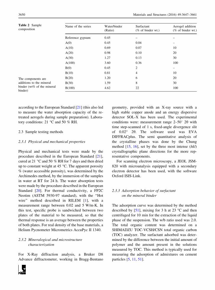
Table 2 Sample
composition
The components are
additions to the mineral
binder (wt% of the mineral
binder)
Name of the series Water/binder Surfactant Aerogel addition
(Ratio) (% of binder wt.) (% of binder wt.)
Reference gypsum 0.45 – –
A(0) 0.45 0.04 –
A(10) 0.69 0.07 10
A(20) 0.98 0.10 20
A(30) 1.27 0.13 30
A(100) 3.60 0.36 100
B(0) 0.45 2 –
B(10) 0.81 4 10
B(20) 1.20 6 20
B(30) 1.59 8 30
B(100) 4.62 22 100
3650 Materials and Structures (2016) 49:3647–3661

3 Results
3.1 Mineral binder analysis by XRD
The XRD analysis of the unhydrated mineral binder
shows a concentration of 59 % of CaSO4 (anhydrite,
the main component), a concentration of 32 % of
CaSO4�0.5 H2O (bassanite) and around 9 % of impu-
rities: 2 % of quartz (SiO2), and 7 % of phyllosilicates
(bulk represented by the KAl3Si3O10(OH)2—Mus-
covite pattern).
The main mineral binder was obtained by the
calcination of natural gypsum (with impurities) from
temperatures from 300 to 700 �C; this process can
generate a resulting product that contains bassanite,
anhydrite III (that transforms into bassanite a few
hours after cooling), and anhydrite II-s or anhydrite II-
u, as also reported by other authors [9, 28, 59, 71].
3.2 Aerogel water absorption
During samples preparation, the aerogels showed
evidence of different water absorption capacities
depending on the concentration of the surfactant in
the solution. To some extent this can be assessed by
analyzing the amount of water needed for series to
reach the fixed flowability (measured by the flow
table method). For this we consider that the water
required can be distributed into two parts: one for the
binder and one for the aerogel. Considering for the
binder a water/binder ratio of 0.40, we then calculate
the binder to aerogel ratio of the remaining portion of
the added water, which is considered to be absorbed
into the aerogel particles. To consider that this extra
amount of water is absorbed by the aerogel, is
supported by the observation that in both series the
ratio of extra water to aerogel mass is roughly
constant.
In particular, the A series showed a constant 2.9 g
of absorbed water per aerogel gram between A(10) to
A(30) series, with a 10 % increase of the water needed
for the A(100) composites. The B series showed a
constant 3.7 g of absorbed water per aerogel gram
between B(10) to B(30) series, with an 8 % increase of
the water needed for the B(100) composites. The
increase of the water by the 100 % aerogel addition is
probably because of the low volume ratios of the
mineral binder, requiring additional water to maintain
the flowability, therefore, it is not considered to be
absorbed by the aerogel particles. However, between
the different composite series, the modified aerogel
granules of the B series absorbed 27.6 % more water
than the aerogels of the A series.
3.3 Adsorption behavior of surfactant
on the mineral binder
The adsorption of the surfactant on the mineral binder
is shown in Fig. 1. The adsorption is linear and
complete up to concentrations of 10 mg of surfactant
initial/g of mineral binder. At higher dosages the
fraction of polymer adsorbing decreases slightly. The
plateau adsorption is at 18 mg of surfactant adsorbed/
g of mineral binder and in these suspensions is reached
for a dosage of about 25 mg/g.
3.4 Physical and mechanical properties
of the composites
The apparent porosities (%), water absorption, bulk
density, compressive strength and thermal conductiv-
ity of the samples are shown in Table 3. The aerogel
containing samples with more surfactant showed in
general, lower mechanical strength, higher thermal
conductivity and higher bulk density than the samples
with less surfactant.
In the samples without aerogels, adding the surfac-
tant led to an increase of 19 % of the apparent
porosity. In presence of a 10 wt% (35 % volume) of
aerogel in both A and B series, the increase was 38 %.
However, while further increase in the aerogel addi-
tion increased the apparent porosity of the B series, it
caused porosity to decrease in the A series.
The compressive strength decreases as the content
of aerogel particles increased, as expected. However,
the surfactant concentration also modified the
Fig. 1 Adsorption behavior of the surfactant in the mineral
binder suspensions
Materials and Structures (2016) 49:3647–3661 3651

properties of the composite materials. The A(0) and
B(0) series, compared to the reference gypsum,
showed 10.9 and 34.7 % lower compressive strength
respectively. The A(10) shows 36.7 % higher com-
pressive strength than the B(10), however at the
highest aerogel concentration, the compressive
strength of the A and B series are almost the same.
As shown in Table 3, the reference gypsum (with-
out surfactant) and A(0) and B(0) samples presented
roughly the same thermal conductivity, showing no
significant effect related to different surfactant quan-
tities. However, this situation changes in presence of
aerogel particles, where indeed, not only the aerogel
addition decrease the thermal conductivity, but also
the effect is different between series A and B due to the
amount of surfactant.
3.5 Microstructure study of the composites
by SEM
The SEM images show the most representative
microstructure of each sample (Figs. 2, 3). The refer-
ence gypsum presented irregular pore morphologies
(Fig. 2a). The A(0) and B(0) samples presented similar
irregular pore morphologies (Fig. 2b, c respectively) as
the reference gypsum, but also presented some addi-
tional pores with spherical morphology, not detected in
the reference sample, generated by the surfactant. The
B(0) sample presented a higher concentration of the
spherical pores compared the A(0) sample, consistent to
the increase of surfactant dosage.
Different crystal morphology, growth and
microstructure of gypsum are observed within samples
depending on their aerogel contents (Fig. 3). The
reference gypsum, the A(0) and the B(0) samples
present crystals with a tabular morphology sized from
1 9 1 9 5 to 2 9 2 9 10 lm, however, the samples
A(0) and B(0) present also some smaller crystals, with
crystal sizes up to 0.5 9 0.5 9 1 lm generated by the
surfactant dosage increase (Fig. 3a).
The SEM images show crystallization of gypsum at
the aerogel-gypsum interface in all cases. The crystal
growth behavior and morphology changed when the
aerogel particles were present, especially in the
highest aerogel addition samples (B(100), Fig. 3c),
leading to tabular, planar and needle like crystals with
sizes up to 0.5 9 0.5 9 15 lm. No visible changes
regarding the crystal morphologies were detected
between A and B series containing aerogel particles.
3.6 Anhydrite hydration by XRD
The X-Ray analysis results shows the different
mineralogical phases obtained after hydration for both
the low and high concentration of surfactant as well as
for the different aerogel contents.
Table 4 shows the evolution of the different
mineralogical phases during the hydration of the
Table 3 Physical properties of the samples at 7 days. Standard deviation presented in brakets
Name of
the series
Apparent
porosity (%)
Water absorption
(m2 min0.5)
Bulk density
(g cm-3)
Compressive
strength (MPa)
Thermal conductivity
(W/m 9 K)
Aerogel
Volume (%)
Reference
gypsum
21 (0.3) 0.5 (0.027) 1.38 (0.006) 19.3 (0.77) 0.282 ± 0.014 –
A(0) 25 (0.2) 0.9 (0.022) 1.36 (0.01) 17.2 (0.19) 0.283 ± 0.014 –
A(10) 29 (0.7) 1.8 (0.079) 0.68 (0.006) 0.82 (0.11) 0.096 ± 0.005 34.5
A(20) 28 (0.3) 2.0 (0.099) 0.47 (0.003) 0.13 (0.01) 0.059 ± 0.003 44.2
A(30) 26 (0.6) 2.1 (0.059) 0.37 (0.03) 0.06 (0.004) 0.059 ± 0.003 47.9
A(100) 19 (1.8) 1.6 (0.064) 0.20 (0.01) 0.01 (0.002) 0.028 ± 0.001 57.1
B(0) 25 (0.2) 0.7 (0.026) 1.30 (0.016) 12.6 (0.35) 0.282 ± 0.014 –
B(10) 29 (0.4) 1.5 (0.083) 0.73 (0.01) 0.60 (0.01) 0.074 ± 0.004 35.8
B(20) 34 (0.6) 2.7 (0.061) 0.48 (0.01) 0.11 (0.04) 0.072 ± 0.004 43.4
B(30) 35 (0.2) 2.9 (0.082) 0.39 (0.02) 0.05 (0.003) 0.065 ± 0.003 49.5
B(100) 36 (4.0) 2.9 (0.086) 0.22 (0.004) \0.01 (0.001) 0.034 ± 0.002 59.2
No standard deviation for thermal conductivity are given because only single measurements were performed, each however, giving
the average of two samples, as explained in the methods section
3652 Materials and Structures (2016) 49:3647–3661

calcium sulfates within the samples from XRD
analysis, without impurities. Moreover, there is a
certain heterogeneity among the samples, primarily
concerning the phyllosilicates.
After 7 days, the gypsum with a 0.45 water/binder
(w/b) ratio, presented an almost complete anhydrite/
bassanite hydration, with a remaining unhydrated
anhydrite and bassanite of 7 and 3 % respectively.
The addition of surfactant reduces by around 6 %
the hydration of the calcium sulfates compared to the
reference gypsum. In presence of aerogel granules, the
formation of gypsum is also reduced as the addition of
aerogel content is increased. However the A series
presented higher quantities of anhydrite and hemihy-
drate compared to the B series.
4 Discussion
It has been shown that it is possible to compatibilize
hydrophobic silica aerogels particles with water-based
mineral binders to form highly insulating composites
Fig. 2 SEM of the reference gypsum—a (9100), A(0)—b (9100) and B(0)—c (9100)
Fig. 3 SEM of the most representative samples: B(0)—a (92000), B(10)—b (92000) and B(100)—c (92000)
Table 4 Semiquantification (%) and analysis of the degree of hydration (DOH) of the calcium sulfates by XRD at 7 days
Phase Reference
gypsum
A(0) A(10) A(20) A(30) A(100) B(0) B(10) B(20) B(30) B(100)
Gypsum (%) 90 84 86 89 84 74 83 94 92 88 85
Bassanite (%) 3 1 1 2 3 7 1 2 3 5 8
(DOH) 0.91 0.97 0.97 0.94 0.91 0.80 0.97 0.94 0.91 0.86 0.77
Anhydrite (%) 7 15 13 9 14 19 16 4 5 7 7
(DOH) 0.89 0.77 0.80 0.86 0.78 0.71 0.75 0.94 0.92 0.89 0.89
Materials and Structures (2016) 49:3647–3661 3653

by using a surfactant to modify the aerogel’s interac-
tion with water. In view of understanding the factors
that control the performance of the resulting compos-
ites, a systematic study was performed using two
different dosages of surfactant and several different
aerogel contents.
4.1 Water accessible porosity
The surfactant modifies the aerogel surface generating
a hydrophilic coating around the hydrophobic core.
Depending on the amount of surfactant added, the
amount of water that penetrates into the aerogel
granules varies; however, there is a minimum surfac-
tant dosage needed to change the aerogel’s hydropho-
bic behavior and to allow the formation of a slurry. For
the surfactant used in this study, this amount has been
found at a 0.1 % wt. addition with respect to water. To
notice that the interaction of the aerogel particles with
water changes suddenly at the mentioned surfactant
amount, thus lowering the surfactant addition does not
provide the compatibility needed to form slurries. This
results into a fixed amount of water and a fixed amount
of surfactant related to the aerogel addition, to which
the water needed by the mineral binder to form a slurry
must be added. The relationship between the surfac-
tant and the water suggests that the surface tension of
the solution should be decreased enough to be able to
form the slurries.
An interesting result is that although more water is
needed as the aerogel content is increased, this amount
is roughly constant with respect to the mass of aerogel
particles and this regardless of the surfactant dosage.
This suggests that a constant amount of water is
absorbed in the aerogels. Further increase of the
amount of surfactant will increase the aerogel’s water
absorption (up to 3.7 grams of water per aerogel gram,
for a 5 % wt. surfactant addition in respect to water).
4.2 Engineering properties of composites
4.2.1 Mechanical behavior of composites
The final distribution by volume of the components
within the mixtures in the fresh state, set (both dry and
water saturated) is presented in Fig. 8. These values
are calculated using the skeletal density of the aerogel
particles, the particle density, the water absorbed by
the aerogel particles and the surfactant adsorbed by the
mineral binder. The gypsum formation of each
sample, in the dry state, is calculated by the DOH
measured by XRD. They provide a basis for more
detailed consideration of the water distribution in
these samples.
In particular, they highlight the fact that during
sample preparation, the aerogel particles are capable
of absorbing not only a very high amount of water, but
also of surfactant. This value is obtained by consid-
ering that in the sample preparation the surfactant
solution first reaches an equilibrium with the mineral
binder, so the surfactant concentration decreases in
relation to the data presented in Fig. 1. Using the
reduced concentration and the amount of liquid
invading the aerogel we can calculate the amount of
surfactant that can be considered to have been
absorbed into this material. This provides a lower
bound for the amount of surfactant absorbed in the
aerogel, assuming that the surfactant does not get
displaced from the mineral binder to the aerogel owing
to a higher adsorption energy on the latter.
Moreover, as observed in Fig. 4, the addition of
aerogel and surfactant together increase the air content
within the mixtures, by a constant of 0.7 m3 and
0.6 m3 of air per m3 of aerogel for the low and high
surfactant content respectively (Fig. 5).This unex-
pected behavior generates an air volume of around
40 %, which decreases the volume fraction of aerogel
and the gypsum, compromising both thermal conduc-
tivity and strength.
Also, as shown before in Fig. 2, the surfactant
causes an increase in the air content in absence of
aerogel particles, forming air bubbles. This is
explained by the fact that the surfactant molecules
tend to minimize unfavorable interactions between the
liquid phase and the surfactant lipophilic tail, aligning
to form amonolayer at the interface between the liquid
phase and the compressed air. The air bubbles are
stabilized in the slurry by the electrostatic and steric
repulsions of the surfactants; the interfacial properties
at the air bubble surfaces are determined by its
physical and chemical properties given by the nature
and concentration of the surfactants [19]. This surfac-
tant foaming ability has been well established and
studied by other authors [19, 46, 49, 70, 73]. Never-
theless, in presence of aerogel particles, no stabilized
air bubbles within the composites were detected;
although, an important amount of air entrained is
measured.
3654 Materials and Structures (2016) 49:3647–3661

The inclusion of aerogel increases the total porosity
as expected (Fig. 6). However, as observed in Fig. 4,
only part of the total porosity can be assigned to the
aerogel structure, while another important part is
located within the gypsum matrix. Interestingly, the
water accessible porosity of these composites is lower
than the volume of air entrained within the gypsum
matrix, which suggests that in the set composites,
water does not partially invade the aerogel, unlike as in
the fresh state. Nevertheless, the water accessible
porosity between the A and B series (with different
surfactant ratio) is quite different (Fig. 6). The highest
surfactant ratio leads to an increased water uptake (B
Fig. 4 Components of the composites by volume (m3) in fresh, set and water saturated state
Fig. 5 Volume of air entrained into the mixture by aerogel unit volume (m3)
R² = 0,999R² = 0,931R² = 0,992R² = 0,855
0%10%20%30%40%50%60%70%80%90%
100%
0% 10% 20% 30% 40% 50% 60%
Poro
sity
(%)
Aerogel volume (%)
A - TotalA - Water AccessibleB - TotalB - Water Accessible(A) Total(A) W.A.(B) Total(B) W.A.
Fig. 6 Total and Water accessible porosities (%) per aerogel
volume (%) of samples
Materials and Structures (2016) 49:3647–3661 3655
series), as can be expected for the modified aerogel’s
hydrophobic to hydrophilic behavior. However, the
samples with the lowest surfactant ratio (A series)
show a decreasing water accessible porosity with
increasing aerogel content. Here the primary
hydrophobic nature of the aerogels themselves and
the lower surfactant dosage can be argued to account
for this behavior.
Therefore, depending on the surfactant and aerogel
concentration, it can be achieved different water
absorption capacities within the composites.
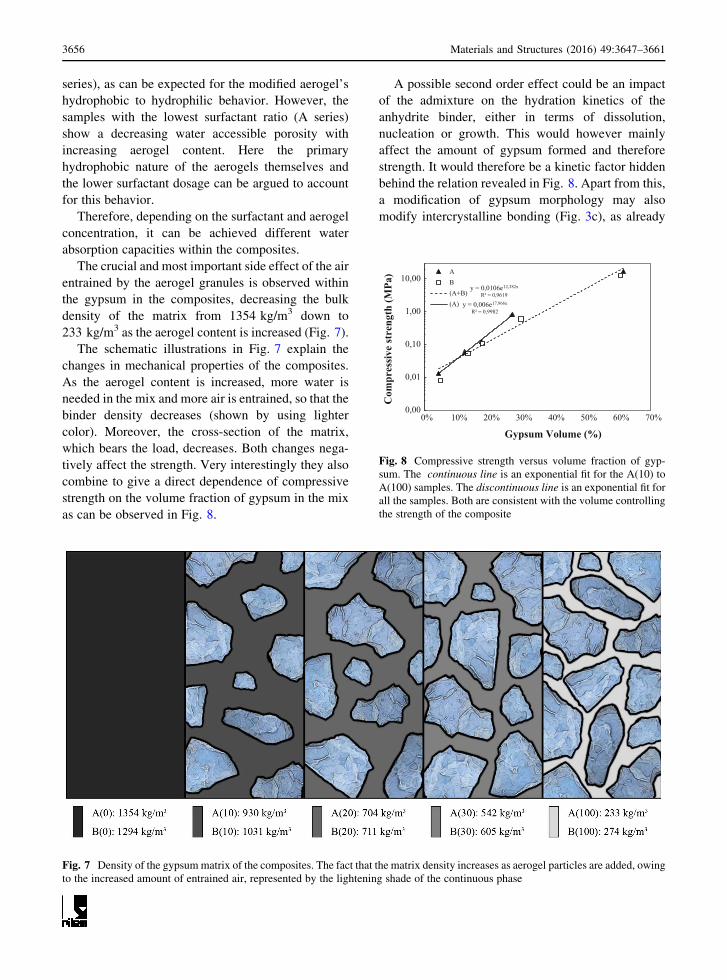
The crucial and most important side effect of the air
entrained by the aerogel granules is observed within
the gypsum in the composites, decreasing the bulk
density of the matrix from 1354 kg/m3 down to
233 kg/m3 as the aerogel content is increased (Fig. 7).
The schematic illustrations in Fig. 7 explain the
changes in mechanical properties of the composites.
As the aerogel content is increased, more water is
needed in the mix and more air is entrained, so that the
binder density decreases (shown by using lighter
color). Moreover, the cross-section of the matrix,
which bears the load, decreases. Both changes nega-
tively affect the strength. Very interestingly they also
combine to give a direct dependence of compressive
strength on the volume fraction of gypsum in the mix
as can be observed in Fig. 8.
A possible second order effect could be an impact
of the admixture on the hydration kinetics of the
anhydrite binder, either in terms of dissolution,
nucleation or growth. This would however mainly
affect the amount of gypsum formed and therefore
strength. It would therefore be a kinetic factor hidden
behind the relation revealed in Fig. 8. Apart from this,
a modification of gypsum morphology may also
modify intercrystalline bonding (Fig. 3c), as already
Fig. 7 Density of the gypsummatrix of the composites. The fact that the matrix density increases as aerogel particles are added, owing
to the increased amount of entrained air, represented by the lightening shade of the continuous phase
y = 0,0106e12,382x
R² = 0,9619
y = 0,006e17,966x
R² = 0,9982
0,00
0,01
0,10
1,00
10,00
0% 10% 20% 30% 40% 50% 60% 70%
Com
pres
sive
stre
ngth
(MPa
)
Gypsum Volume (%)
AB(A+B)(A)
Fig. 8 Compressive strength versus volume fraction of gyp-
sum. The continuous line is an exponential fit for the A(10) to
A(100) samples. The discontinuous line is an exponential fit for
all the samples. Both are consistent with the volume controlling
the strength of the composite
3656 Materials and Structures (2016) 49:3647–3661

proposed elsewhere [62]. However, the impact of
hydrate morphology on strength is beyond the scope of
this paper, and while probably of second order
important, it is nevertheless something that we hope
to investigate in the future.
4.2.2 Thermal conductivity of composites
The thermal conductivity of our composites depend on
the volume fractions and thermal conductivities of
gypsum, aerogel and air. In what follows we propose a
way to estimate this on the basis of the proportions of
these three phases. In particular, it is proposed to
handle this in a two stage process. We emphasize here
that the assumption of a fixed w/b in the matrix only
affects the composition listed for the fresh state in
Fig. 4, but not the dry state ones, which are those used
in the model.
First we calculate the thermal conductivity of the
matrix, considered as a mixture of air (phase A) and
gypsum (phase B). In a second step, calculate the
conductivity of the composite, considered as mixture
of the aerogel (phase A*) and of the matrix (Phase B*)
determined in the first step. In both steps we use the
same mixing rules to calculate the composite conduc-
tivity based on [33]. This relies on calculating upper
(kU) and lower (kL) bounds of the thermal conductivity
using the following equations:
Model AðUpper boundÞ: kU¼ kB þ ;A=
1
kA � kBþ 1� ;A
3kB
� �ð1Þ
Model BðLower boundÞ:kL¼ kA þ ð1� ;AÞ=
1
kB � kAþ ;A3kA
� �ð2Þ
;A = Phase A volume fraction, kA = Phase A k,
kB = Phase B k.
The authors of this model initially proposed to use
the arithmetic mean of the kU and kL to evaluate the
thermal conductivity of the composite material. How-
ever, we found that for our composites, the geometric
mean provides results in much better agreement with
our experimental data. Therefore in both steps we
calculate the composite thermal conductivities as:
Model C: k ¼ffiffiffiffiffiffiffiffiffiffikUkL
pð3Þ
Numerical applications were done using the following
thermal conductivity values for the phases: kAero-
gel = 0.013 W/m 9 K, kBinder = 1.25 W/m 9 K
(Gypsum solid phase) from [33] and kAir = 0.026 -
W/m 9 K, while the volume fractions of the phases
come from our measurements reported in Fig. 4.
The model predicts extremely well all our mea-
surements without the inclusion of any fitting param-
eter, as shown in Fig. 9. We can therefore conclude
that this model can reliably be used to estimate thermal
conductivities having compositions in the range of
those reported in this work. It does however have some
limitations, in particular the link between scales.
Indeed, including a phase in one or another level of the
homogenization procedure does not lead to the same
result. The definition of the phases to be included at
each stage of the homogenization is therefore crucial.
In our samples, taking air and gypsum as first level,
leads to good results. However, this should not obscure
the risk misinterpretations that may result in applying
the same model to other systems.
4.3 Towards an optimization of aerogel
composites
In practical terms, the optimization of these composites
will involve a compromise between reducing thermal
conductivity and losing strengthwhen the aerogel content
is increased. From this perspective, it is useful to plot
compressive strength versus thermal conductivity as in
0,000
0,050
0,100
0,150
0,200
0,250
0,300
0,350
0,000 0,050 0,100 0,150 0,200 0,250 0,300 0,350
The
rmal
con
duct
ivity
k(W
/m. K
) -P
redi
cted
Thermal conductivity k (W/m.K) - Measured
Fig. 9 Plot of thermal conductivity showing experimental
values versus those predicted with the model based on
Eqs. (1)–(3). The continuous line represents the data obtained
from the proposed model according to the respective volume
proportions in our study
Materials and Structures (2016) 49:3647–3661 3657

Fig. 10. This reveals a relation between both properties,
highlighting the difficulty of substantially increasing
strength at a defined thermal conductivity.
In practical terms significant strength improve-
ments, may not be easily noticeable in Fig. 10 because
of the logarithmic scale. For this reason, we included
the two discontinuous lines representing respectively
an improvement and a worsening of strength by a
factor 5. Achieving such a strength increase without
changing the thermal conductivity would already be
very interesting in practice. Such effects are within the
‘‘scatter’’ of the data reported in Fig. 10, suggesting
that second order effects can play an important effect
in this optimization process.
These changes may relate to modifications of the
microstructure. Although of second order with respect
to the main factor of gypsum content, they probably
offer useful avenues to exploit for optimization. For
example only may consider trying to eliminate the air
entrained during the preparation of thesematerials as it
does not contribute to strength and has a higher
thermal conductivity that the aerogel granules (en-
trained air is about 40 % by volume as shown in
Fig. 4). This would probably worsen the fluidity of the
paste, which would then possibly have to be adjusted
by the inclusion of chemical admixtures such as
superplasticizers [23, 29].
This optimization of component proportions would
include two main options. The first is to replace the
volume of entrained air with aerogel to reduce the
overall thermal conductivity. This would not change
the volume fraction of gypsum and should conse-
quently leave the strength unchanged in accordance
with Fig. 8. The second option consists in increasing
strength without changing the thermal conductivity.
For this, the right proportion of gypsum and aerogel
must be determined for replacing the air. Changes in
strength would be best estimated using the exponential
fit of the A(10) to A(100) samples presented as the
continuous line in Fig. 8.
The thermal conductivity can be estimated using
our model. Because of the previously mentioned issue
of homogenization, the same two step procedure
would be used. Here however, in the first step the air
volume would be replaced by a mixture of gypsum and
inclusions having the same thermal conductivity as the
aerogel. Following this procedure, we find that the
changes proposed would provide substantial improve-
ments as can be observed in Fig. 11.
Replacing the volume of entrained air by aerogel
would improve the overall thermal insulation of the
composites, as shown in Fig. 11. Fixing the volume of
gypsum, and thereby the strength would decrease the
thermal conductivity of the samples by about 20 %,
providing a very interesting ultralow thermal conduc-
tivity of 23 mW/m9 K for our A0(100) and 63 mW/m
9 K for A0(10). Moreover, modifying the volume of
gypsum and fixing the thermal conductivity value
would improve the strength significantly: 82.5 %
(0.024 MPa) and 227.4 % (2.57 MPa) respectively
for A00(100) and A00(10). Figure 11 also shows what
would happen if all the aerogel were replaced by air,
0,00
0,01
0,10
1,00
10,00
100,00
0,00 0,01 0,10 1,00
Com
pres
sive
stre
ngth
(MPa
)
Thermal conductivity k (W/m.K)
AB(A+B)(A+B) C. Strengthby a Factor +/- 5
Fig. 10 Experimental values of thermal conductivity versus
compressive strength. The continuous line corresponds to a
power law that fits all the data points presented in the graph. The
dotted lines represent an increase and decrease of the
compressive strength by a Factor of 5
0,01
0,10
1,00
0,02 0,20
Com
pres
sive
stre
ngth
(MPa
)
Thermal conductivity k (W/m.K)
Fig. 11 Predicted values of thermal conductivity versus
compressive strength. The continuous line corresponds to the
data calculated with a 40 % of air by volume (A). The dashed
line corresponds to the replacement of the mentioned air by
aerogel (A0). The dash-dotted line corresponds to a replacement
of the aerogel by air (A00)
3658 Materials and Structures (2016) 49:3647–3661

without changing the content of gypsum. The thermal
conductivity would increase by 57 % for A00(10) andby 72 % for A00(100) compared to the corresponding
samples A0(10) and A0(100) respectively. This clearlyillustrated the benefit of using aerogel to enhance the
thermal insulation capacity of these composites.
Finally, we can also mention that changes in mor-
phologies of hydrates may be beneficial, for example by
enhancing the intercrystalline bonding in the matrix and/
or the bonding between the granules and the matrix. Our
results show that such changes take place, but a detailed
discussion of how to exploit this in an optimization
procedure is beyond the scope of this article.
5 Conclusions
Ultra lightweight (around 200 kg/m3) and high ther-
mal insulating (around 30 mW/m 9 K) gypsum
composites can be achieved by the addition of a
100 % by wt. of nanoporous hydrophobic aerogel
particles through a hydrophilization process in order to
stabilize the composite slurries, as showed in the
present study. However, an around 40 % of air volume
content entrained can be found within the mixtures,
lowering the mechanical properties more than
expected. Moreover, by changing the hydrophobic
behavior of the aerogels with surfactants (at least a
0.1 % addition to the mixture’s solution) very high/
binder ratios are required, possibly affecting the
hydration of the anhydrite binder.
This type of composite can be suitable for exterior
renderings on buildings. If used as a single layer, the
optimum aerogel particles might be considered at a 10
by wt% (with a k between 74 and 96mW/m 9 K). The
composites with 100 % by wt. aerogel addition could
be used as insulating layers, once future material
optimization is done (to reach at least 0.08 MPa), but
requiring a protective exterior layer, which can be the
anhydrite-based mortar presented in this experiment.
However, the improved insulating layer should be
reinforced with a mesh, as other products in the
market. Nevertheless, the experiments and analysis
presented in this paper, set as a basis for future
material development, requiring additional experi-
ments regarding the application of these composites as
an exterior thermal insulating renderings, like weath-
ering chamber tests and large scale specimens, or
energy efficiency analysis. Moreover, additives like
superplasticizers to reduce the mixture water content
and its effect on the anhydrite will also be studied.
Acknowledgments The authors wish to show their gratitude
to the Centre for Research Assistance of Geological Techniques
Laboratory of the Complutense University of Madrid, and the
ConstructionMaterials Laboratory of the School of Architecture
of the Polytechnic University of Madrid for supporting us with
the laboratory equipment and facilities. Special thanks to Dr.
Marta Palacios from Institute for Building Materials of ETH
Zurich for her technical assistance. We want to thank CTH
Navarra (Spain) for the anhydrite supply, and BASF (Spain-
Germany) for the surfactant supply. Also, we want to show our
gratitude to Aidico Laboratories (Valencia) for the thermal
conductivity measurements.
References
1. AAC_11.3_RILEM (1992) Determination of the thermal
conductivity of oven dry AAC (dynamic method)
2. Abenza-Ruiz B (2009) Aplicacion del yeso en exteriores:
analisis de dosificaciones en laboratorio y estudio de campo
en la ciudad de Cuenca. Paper presented at the Historia de la
Construccion, Valencia
3. Achard P, Rigacci A, Echantillac T, Bellet A, Aulagnier M,
Daubresse A (2011) Insulating Silica Xerogel plaster. WO
2011083174, 14-Jul-2011
4. Akimov YK (2003) Fields of Application of Aerogels
(Review). Instrum Exp Tech 46:287–299
5. Alonso MM, Palacios M, Puertas F (2013) Compatibility
between polycarboxylate-based admixtures and blended-
cement pastes. Cement Concr Compos 35:151–162. doi:10.
1016/j.cemconcomp.2012.08.020
6. Anhydrite II. http://www.cthnavarra.com/cth/web/cth/webcth.
nsf/app/Producto/Yeso/Myrsac802. http://www.cthnavarra.com/
cth/web/cth/webcth.nsf/app/Producto/Yeso/Myrsac802
7. Baetens R, Jelle BP, Gustavsen A (2011) Aerogel insulation
for building applications: a state-of-the-art review. Energy
Build 43:761–769. doi:10.1016/j.enbuild.2010.12.012
8. Baetens R, Jelle BP, Thue JV, Tenpierik MJ, Grynning S,
Uvsløkk S, Gustavsen A (2010) Vacuum insulation panels
for building applications: a review and beyond. Energy
Build 42:147–172. doi:10.1016/j.enbuild.2009.09.005
9. Ballirano P, Melis E (2009) The thermal behaviour of
gamma-CaSO4. Phys Chem Miner 36:319–327. doi:10.
1007/s00269-008-0280-0
10. Bauer U, Doshi D (2010) Aerogel compositions and meth-
ods of making and using them. WO 2010126792 A1,
04-Nov-2010
11. Bowen P, Houst YF, Palacios M, Puertas F (2009)
Adsorption of superplasticizer admixtures on alkali-acti-
vated slag pastes. Cem Concr Res 39:670–677
12. Cabot Aerogel. http://www.cabotcorp.com/solutions/applic
ations/construction/building-insulation. http://www.cabotc
orp.com/solutions/applications/construction/building-insulation
13. Colak A (2000) Density and strength characteristics of
foamed gypsum. Cement Concr Compos 22:193–200.
doi:10.1016/S0958-9465(00)00008-1
Materials and Structures (2016) 49:3647–3661 3659

14. Chen K (2013) Truss core sandwich panels with compacted
aerogel insulation. Master Thesis, MIT
15. Chung F (1974) Quantitative interpretation of X-ray
diffraction patterns of mixtures. I. Matrix-flushing method
for quantitative multicomponent analysis. J Appl Crystal-
logr 7:519–525. doi:10.1107/S0021889874010375
16. Chung F (1974) Quantitative interpretation of X-ray
diffraction patterns of mixtures. II. Adiabatic principle of
X-ray diffraction analysis of mixtures. J Appl Crystallogr
7:526–531. doi:10.1107/S0021889874010387
17. Dalmay P, Smith A, Chotard T, Sahay-Turner P, Gloaguen
V, Krausz P (2010) Properties of cellulosic fibre reinforced
plaster: influence of hemp or flax fibres on the properties of
set gypsum. J Mater Sci 45:793–803. doi:10.1007/s10853-
009-4002-x
18. Doshi D, Miller T, Chase J, Norwood C (2011) Aerogel
composites and methods for making and using them. US
Patent 0206471, 25 Aug 2011
19. Du L, Folliard KJ (2005) Mechanisms of air entrainment in
concrete. Cem Concr Res 35:1463–1471. doi:10.1016/j.
cemconres.2004.07.026
20. EN_1015-18 (2003) European Standard EN 1015-18,
Methods of tests for mortar for masonry. Part 18: Deter-
mination of water absorption coefficient due to capillary
action of hardened mortar
21. EN_13279-2 (2004) European Standard EN 13279-2,
Gypsum binders and gypsum plasters—test methods
22. Ferrandiz-Mas V, Garcıa-Alcocel E (2013) Durability of
expanded polystyrene mortars. Constr Build Mater
46:175–182. doi:10.1016/j.conbuildmat.2013.04.029
23. Flatt RJ, Schober I (2012) Superplasticizers. In: Roussel N
(ed) Understanding the rheology of concrete. Woodhead
Publishing, Cambridge, pp 144–208
24. Frank D, Zimmermann A, Stuhler H (2000) Composite
material containing aerogel, process for manufacturing the
same and the use thereof. US 6080475, 27-Jun-2000
25. Gao T, Jelle BP, Gustavsen A, Jacobsen S (2014) Aerogel-
incorporated concrete: an experimental study. Constr Build
Mater 52:130–136. doi:10.1016/j.conbuildmat.2013.10.100
26. Garcıa-Santos A (2009) PPF-reinforced, ESP-lightened
gypsum plaster. Materiales de Construccion 59:105–124
27. Gibiat V, Lefeuvre O, Woignier T, Pelous J, Phalippou J
(1995) Acoustic properties and potential applications of
silica aerogels. Proc Fourth Int Symp AEROGELS
186:244–255. doi:10.1016/0022-3093(95)00049-6
28. Gipsdatenbuch (2006). Bundesverband der Gipsindustrie
e.V
29. Hampel C, Zimmermann J, Muller M (2013) Optimisation
of plasticizers for gypsum applications. Anglais 2:56–61
30. Hanus MJ, Harris AT (2013) Nanotechnology innovations
for the construction industry. ProgMater Sci 58:1056–1102.
doi:10.1016/j.pmatsci.2013.04.001
31. Herrero S, Mayor P, Hernandez-Olivares F (2013) Influence
of proportion and particle size gradation of rubber from end-
of-life tires on mechanical, thermal and acoustic properties
of plaster–rubber mortars. Mater Des 47:633–642. doi:10.
1016/j.matdes.2012.12.063
32. Hong SK, Yoon MY, Hwang HJ (2011) Fabrication of
spherical silica aerogel granules from water glass by
ambient pressure drying. J Am Ceram Soc 94:3198–3201.
doi:10.1111/j.1551-2916.2011.04765.x
33. K-i Horai (1971) Thermal conductivity of rock-forming
minerals. J Geophys Res 76:1278–1308. doi:10.1029/
JB076i005p01278
34. Hughes JJ (2012) RILEM TC 203-RHM: repair mortars for
historic masonry : e of mortar in masonry: An introduction
to requirements for the design of repair mortars. Mater
Struct Mater Construct 45:1287–1294. doi:10.1617/s11527-
012-9847-9
35. Kazuma K (2011) Development of Silica-based Aerogels
for Super-insulating Glazing Application. Engineering
Degree, Kyoto University
36. Kim S, Seo J, Cha J, Kim S (2013) Chemical retreating for
gel-typed aerogel and insulation performance of cement
containing aerogel special section on recycling wastes for
use as. Construct Mater 40:501–505. doi:10.1016/j.
conbuildmat.2012.11.046
37. Koebel M, Rigacci A, Achard P (2012) Aerogel-based
thermal superinsulation: an overview. J Sol–Gel Sci Tech-
nol 63:315–339
38. Kunzel HM, Karagiozis A (2010) 2—Hygrothermal beha-
viour and simulation in buildings. In: Hall MR (ed) Mate-
rials for energy efficiency and thermal comfort in buildings.
Woodhead Publishing, Cambridge, pp 54–76. doi:10.1533/
9781845699277.1.54
39. Kwon Y-G, Choi S-Y, Kang E-S, Baek S-S (2000) Ambi-
ent-dried silica aerogel doped with TiO2 powder for thermal
insulation. J Mater Sci 35:6075–6079. doi:10.1023/A:
1026775632209
40. La Spina V, Mileto C, Vegas F (2013) The historical ren-
derings of Valencia Spain: an experimental study. J Sci
Technol Safeguard Cult Herit Mediterranean Basin 14:S44–
S51. doi:10.1016/j.culher.2012.11.011
41. Lazghab M, Saleh K, Guigon P (2008) A new solventless
process to hydrophobize silica powders in fluidized beds.
AIChE J 54:897–908. doi:10.1002/aic.11436
42. Li G, Yu Y, Zhao Z, Li J, Li C (2003) Properties study of
cotton stalk fiber/gypsum composite. Cem Concr Res
33:43–46. doi:10.1016/S0008-8846(02)00915-8
43. Liu H, Sha W, Cooper AT, Fan M (2009) Preparation and
characterization of a novel silica aerogel as adsorbent for
toxic organic compounds. Interfaces Against Pollution 5th
International Conference on Interfaces Against Pollution
2008, Kyoto, Japan, 1-4 June 2008 347:38–44. doi:10.1016/
j.colsurfa.2008.11.033
44. Middendorf B (2002) Physico-mechanical and microstruc-
tural characteristics of historic and restorationmortars based
on gypsum: current knowledge and perspective. doi:10.
1144/GSL.SP.2002.205.01.13
45. MielkeM, von Dungen K (1997) Moldings containing silica
aerogel particles and their preparation. US 5656196
46. Mydin MAO, Wang YC (2012) Mechanical properties of
foamed concrete exposed to high temperatures. Constr
Build Mater 26:638–654. doi:10.1016/j.conbuildmat.2011.
06.067
47. Neugebauer A, Chen K, Tang A, Allgeier A, Glicksman LR,
Gibson LJ (2014) Thermal conductivity and characteriza-
tion of compacted, granular silica aerogel. Energy Build
79:47–57. doi:10.1016/j.enbuild.2014.04.025
48. Oliver A, Nelia F, Garcıa A (2010) Caracterizacion termica
de placas de yeso con material de cambio de fase incorpo-
rado Informes de la Construccion 62
3660 Materials and Structures (2016) 49:3647–3661

49. Ouyang X, Guo Y, Qiu X (2008) The feasibility of synthetic
surfactant as an air entraining agent for the cement matrix.
Constr Build Mater 22:1774–1779. doi:10.1016/j.conbuildmat.
2007.05.002
50. Pacheco-Torgal F (2014) Eco-efficient construction and
building materials research under the EU Framework Pro-
gramme Horizon 2020. Constr Build Mater 51:151–162.
doi:10.1016/j.conbuildmat.2013.10.058
51. Palacios M, Flatt RJ, Puertas F, Sanchez-Herencia A (2012)
Compatibility between polycarboxylate and viscosity-
modifying admixtures in cement pastes. Spec Publ. doi:10.
14359/51684218
52. Pigache MR (1986) El enlucido exterior de yeso en las
rehabilitaciones de las fachadas de Parıs
53. Pluronic. http://www.basf.com/group/corporate/en/brand/
PLURONIC
54. Rao AV, Pajonk GM, Bhagat SD, Barboux P (2004) Com-
parative studies on the surface chemical modification of
silica aerogels based on various organosilane compounds of
the type RnSiX4 – n. Aerogels 7 Proceedings of the 7th
International Symposium on Aerogels 7th International
Symposium on Aerogels 350:216–223. doi:10.1016/j.
jnoncrysol.2004.06.034
55. Riffat SB, Qiu G (2013) A review of state-of-the-art aerogel
applications in buildings. Int J Low-Carbon Technol 8:1–6.
doi:10.1093/ijlct/cts001
56. Sanz-Arauz D (2009) Analisis del yeso empleado en
revestimientos exteriores mediante tecnicas geologicas.
PhD Thesis, UPM
57. Sanz-Arauz D, Villanueva L (2004) Albarracın y el yeso
rojo
58. Serhat-Baspınar M, Kahraman E (2011) Modifications in
the properties of gypsum construction element via addition
of expanded macroporous silica granules. Constr Build
Mater 25:3327–3333. doi:10.1016/j.conbuildmat.2011.03.
022
59. Seufert S, Hesse C, Goetz-Neunhoeffer F, Neubauer J
(2009) Quantitative determination of anhydrite III from
dehydrated gypsum by XRD. Cem Concr Res 39:936–941.
doi:10.1016/j.cemconres.2009.06.018
60. Shao L (2010) 25 Materials for energy efficiency and ther-
mal comfort in new buildings. In: Hall MR (ed) Materials
for energy efficiency and thermal comfort in buildings.
Woodhead Publishing, Cambridge, pp 631–648. doi:10.
1533/9781845699277.3.631
61. Shewale PM, Rao AV, Rao AP (2008) Effect of different
trimethyl silylating agents on the hydrophobic and physical
properties of silica aerogels. Appl Surf Sci 254:6902–6907.
doi:10.1016/j.apsusc.2008.04.109
62. Singh NB, Middendorf B (2007) Calcium sulphate hemi-
hydrate hydration leading to gypsum crystallization. Prog
Cryst Growth Charact Mater 53:57–77. doi:10.1016/j.
pcrysgrow.2007.01.002
63. Soleimani Dorcheh A, Abbasi MH (2008) Silica aerogel;
synthesis, properties and characterization. J Mater Process
Technol 199:10–26. doi:10.1016/j.jmatprotec.2007.10.060
64. Stahl T, Brunner S, ZimmermannM, GhaziWakili K (2012)
Thermo-hygric properties of a newly developed aerogel
based insulation rendering for both exterior and interior
applications. Energy Build 44:114–117. doi:10.1016/j.
enbuild.2011.09.041
65. Taylor T, Counsell J, Gill S (2013) Energy efficiency is
more than skin deep: improving construction quality control
in new-build housing using thermography. Energy Build
66:222–231. doi:10.1016/j.enbuild.2013.07.051
66. Ulker Z, Sanli D, Erkey C (2014) Chapter Applications of
aerogels and their composites in energy-related technologies.
In: Anikeev V, FanM (eds) Supercritical fluid technology for
energy and environmental applications. Elsevier, Boston,
pp 157–180. doi:10.1016/B978-0-444-62696-7.00008-3
67. Vimmrova A, Keppert M, Svoboda L, Cerny R (2011)
Lightweight gypsum composites: design strategies for
multi-functionality. Cement Concr Compos 33:84–89.
doi:10.1016/j.cemconcomp.2010.09.011
68. Wagh PB, Ingale SV (2002) Comparison of some physico-
chemical properties of hydrophilic and hydrophobic silica
aerogels. Ceram Int 28:43–50. doi:10.1016/S0272-8842(01)
00056-6
69. Wang D, Silbaugh T, Pfeffer R, Lin YS (2010) Removal of
emulsified oil from water by inverse fluidization of
hydrophobic aerogels. Powder Technol 203:298–309.
doi:10.1016/j.powtec.2010.05.021
70. Wei S, Yiqiang C, Yunsheng Z, Jones MR (2013) Charac-
terization and simulation of microstructure and thermal
properties of foamed concrete. Constr Build Mater
47:1278–1291. doi:10.1016/j.conbuildmat.2013.06.027
71. Wirsching F (2000) Calcium sulfate. In: Ullmann’s ency-
clopedia of industrial chemistry. Wiley-VCH Verlag GmbH
& Co. KGaA. doi:10.1002/14356007.a04_555
72. Wong JCH, Kaymak H, Brunner S, Koebel MM (2014)
Mechanical properties of monolithic silica aerogels made
from polyethoxydisiloxanes. Microporous Mesoporous
Mater 183:23–29. doi:10.1016/j.micromeso.2013.08.029
73. Yang Q, Zhu P, Wu X, Huang S (2000) Properties of con-
crete with a new type of saponin air-entraining agent. Cem
Concr Res 30:1313–1317. doi:10.1016/S0008-8846(00)
00340-9
74. Yokogawa H, Yokoyama M (1995) Hydrophobic silica
aerogels. Proc Fourth Int SympAerogels 186:23–29. doi:10.
1016/0022-3093(95)00086-0
75. Yu QL, Brouwers HJH (2012) Development of a self-
compacting gypsum-based lightweight composite. Cement
Concr Compos 34:1033–1043. doi:10.1016/j.cemconcomp.
2012.05.004
76. Zhao S, Zhang Z, Sebe G, Wu R, Rivera Virtudazo RV,
Tingaut P, Koebel MM (2015) Multiscale assembly of
superinsulating silica aerogels within silylated nanocellu-
losic scaffolds: improved mechanical properties promoted
by nanoscale chemical compatibilization. Adv Funct Mater
25:2326–2334. doi:10.1002/adfm.201404368
Materials and Structures (2016) 49:3647–3661 3661