animal bed rat cryo user manual - university of illinois
TRANSCRIPT

Version
Innovation with Integrity
Animal Bed Rat Cryo
002
User Manual
MRI

Copyright © by Bruker Corporation
All rights reserved. No part of this publication may be reproduced, stored in a retrieval system, or transmitted, in any form, or by any means without the prior consent of the publisher. Product names used are trademarks or registered trademarks of their respective holders.
© December 12, 2014: Bruker Corporation
Fällanden, Switzerland
P/N: Z33107
DWG-Nr.: Z4D12375A 002
For further technical assistance on the Bio Animal Bed Rat Cryo, please do not hesitate to contact your nearest BRUKER representative or contact us directly at:
BRUKER CorporationIndustriestrasse 26CH-8117 FällandenSwitzerlandPhone: + 41 825 97 97FAX: + 41 825 94 04E-mail: [email protected]: www.bruker.com

Z3310
Contents
Contents
1 About ..............................................................................................................31.1 This Manual............................................................................................................. 3
1.2 Policy Statement ..................................................................................................... 3
1.3 Symbols and Conventions....................................................................................... 3
2 Introduction....................................................................................................52.1 General Purpose ..................................................................................................... 5
2.2 Disclaimer................................................................................................................ 5
2.3 Version 002 ............................................................................................................. 5
2.4 Before You Begin .................................................................................................... 5
2.5 The Bruker Service.................................................................................................. 5
3 Product Overview ..........................................................................................73.1 Bio Animal Bed Rat Cryo and Rat Position Gauge ................................................. 7
3.2 Heating Cover ......................................................................................................... 7
4 Handling .........................................................................................................94.1 Provided Tools ........................................................................................................ 9
4.2 Anesthesia and Fixation .......................................................................................... 9
4.3 Balancing Ring ...................................................................................................... 11
4.4 Lifting Mechanism ................................................................................................. 11
4.5 Rat Position Gauge ............................................................................................... 12
4.6 Handling of the Bio Animal Bed Rat Cryo on the MRI System.............................. 13
5 Material & Cleaning .....................................................................................155.1 Material.................................................................................................................. 15
5.2 Cleaning ................................................................................................................ 15
6 Scope of Supply ..........................................................................................176.1 Spare parts for Animal Bed Z140780 ..................................................................... 17
7 Contact .........................................................................................................19
17 / Rev.: 02

Contents
2 Z33107 / Rev.: 02

Z3310
1 About
1.1 This Manual
This manual is intended to be a reference guide for operators and service technicians. It provides detailed information about the user level maintenance and overall use of the Bruker device.
The figures shown in this manual are designed to be general and informative and may not represent the specific Bruker model, component or software/firmware version you are working with. Options and accessories may or may not be illustrated in each figure.
Carefully read all relevant chapters before working on the device!
1.2 Policy Statement
It is the policy of Bruker to improve products as new techniques and components become available. Bruker reserves the right to change specifications at any time.
Every effort has been made to avoid errors in text and figure presentation in this publica-tion. In order to produce useful and appropriate documentation, we welcome your com-ments on this publication. Support engineers are advised to regularly check with Bruker for updated information.
Bruker is committed to provide customers with inventive, high quality products and ser-vices that are environmentally sound.
1.3 Symbols and Conventions
Safety instructions in this manual are marked with symbols. The safety instructions are introduced using indicative words which express the extent of the hazard.
In order to avoid accidents, personal injury or damage to property, always observe safety instructions and proceed with care.
CAUTION
This combination of symbol and signal word indicates a possibly hazardous situation which could result in minor or slight injury unless avoided.
37 / Rev.: 02

About
NOTICE
This combination of color and signal word indicates a possibly hazardous situation which could result in damage to property or the environment unless avoided.
This symbol highlights useful tips and recommendations as well as information designed to ensure efficient and smooth operation.
4 Z33107 / Rev.: 02

Z3310
2 Introduction
2.1 General Purpose
The Bio Animal Bed Rat Cryo (Animal Bed) is suitable for magnetic resonance imaging (MRI) and magnetic resonance spectroscopy (MRS) examinations of rat brains using an MRI CryoProbe. It can be used within BRUKER BioSpec®, PharmaScan® and ClinScan®
systems. The Animal Bed provides a stereotactic fixation and a setup for gas anesthe-sia.
2.2 Disclaimer
The unit should only be used for its intended purpose, as described in this manual. Use of the unit for any purpose other than that for which it is intended is taken only at the users own risk and invalidates all manufacturer warranties.
Service or maintenance work on the unit must be carried out by qualified personnel. Only trained persons should operate the unit.
Read this manual before operating the unit. Pay particular attention to any safety related information.
2.3 Version 002
The manual is written for all ‘Bio Animal Bed Rat Cryo‘ for BRUKER BioSpec®, Phar-maScan® and ClinScan® systems.
2.4 Before You Begin
This user manual contains information that are necessary for a safe operation of the device. Consider all safety references!
2.5 The Bruker Service
Our customer service division is available to provide technical information. See "Con-tact" on page 19 for contact details.
When handling the animal, local regulations must be strictly adhered to.
57 / Rev.: 02

Introduction
6 Z33107 / Rev.: 02

Z3310
3 Product Overview
3.1 Bio Animal Bed Rat Cryo and Rat Position Gauge
The base of the Animal Bed system (Figure 3.1) consists of a half shell made of PEEK with a diameter of 68 millimeters.
3.2 Heating Cover
A heating cover (Figure 3.2 (1)) to stabilize the body temperature of the rat during inves-tigation is provided with the Animal Bed. The heating cover has to be connected to a conventional water heating system.
Figure 3.1: Total view of the Animal Bed and Rat Position Gauge.
[1] Animal support area of the Animal Bed where the animal is positioned
[2] Rear end to guide the Animal Bed into the magnet with lifting arm mechanism to position animal under the Coilhead
[3] Adjustable balancing ring
[4] Rat Position Gauge for testing the correct position of the animal
Figure 3.2: Animal Bed with heating cover (1).
The temperature of the water heating system has to be adjusted in order to stabilize the animals physiological body temperature.
77 / Rev.: 02

Product Overview
8 Z33107 / Rev.: 02

Z3310
4 Handling
4.1 Provided Tools
4.2 Anesthesia and Fixation
CAUTION
Risk of injury!
Therefore:
• When tightening screws within the 0.5 mT line of the magnet only use the non-magnetic screw driver provided with the Animal Bed!
Figure 4.1: Animal support area.
[1] Respiration mask
[2] Slotted headless screw
[3] Extension screw
[4] White fixation screw
[5] PEEK screws
[6] Mechanical stop
[7] White screws
[8] Ear plug holder
[9] Ear plug
Figure 4.2: Bottom view of the animal support area - gas supply.
[1] Silicon tube for narcotic gas supply
[2] Silicon tube for narcotic gas aspira-tion
97 / Rev.: 02

Handling
The animal support area consists of the following parts:
• Anesthetic gas supply:A passive gas anesthesia including supply and aspiration is provided within the res-piration mask (Figure 4.1 (1)). The respiration mask is connected to the two silicon tubes (supply: Figure 4.2 (1), aspiration: Figure 4.2 (2)).
• Respiration mask:The respiration mask can be shifted within a certain range. To reposition the respi-ration mask loosen the white fixation screw (Figure 4.1 (4)).
• Tooth bar:To adjust the position of the tooth bar apply the extension screw (Figure 4.1 (3)) and loosen the slotted headless screw (Figure 4.1 (2)). After positioning the tooth bar fix the slotted headless screw and remove the extension screw.
• Stereotactic fixation:Figure 4.1 (8) shows the stereotactic fixation device which is realized by ear plugs fitting into the ear canals. The stereotactic fixation can be placed in three different positions in reference to the respiration mask. To change the position the white screws (Figure 4.1 (7)) have to be removed. The position of the ear plug within the ear canal can be adjusted by moving the complete ear plug holder (Figure 4.1 (8)) and the ear plugs (Figure 4.1 (9)) independently. To move the complete ear plug holder loosen the white screw (Figure 4.1 (7)). The ear plugs do have a thread and can be moved by using the provided non-magnetic screw driver.
• Mechanical stop:To adjust the position of the object to be imaged in relation to the centre of the Coil-head the mechanical stop (Figure 4.1 (6)) can be moved. To do so, the PEEK screws (Figure 4.1 (5)) has to be loosen. The correct position can be checked by using the Rat Position Gauge ("Rat Position Gauge" on page 12).
Connect the tube of the narcotic gas aspiration to the specific exhaust system within the lab. The specific exhaust system has to be adjusted with the appropriate flow in order to ensure a stable anesthesia of the animal.
NOTICE
Hazardous situation of damaging the Coilhead due to punctiform pressure! Rat can freeze in.
Therefore:
• Remove the extension screw (Figure 4.1 (3)) whenever the bed is used in the Rat Position Gauge or the MRI system.
• It is not allowed to position the respiration mask beyond the end of the Animal Bed otherwise its functionality cannot be guaranteed.
• Place the Animal Bed in the Rat Position Gauge to check for any possible collision with the Coilhead ("Rat Position Gauge" on page 12).
10 Z33107 / Rev.: 02

Z3310
Handling
4.3 Balancing Ring
4.4 Lifting Mechanism
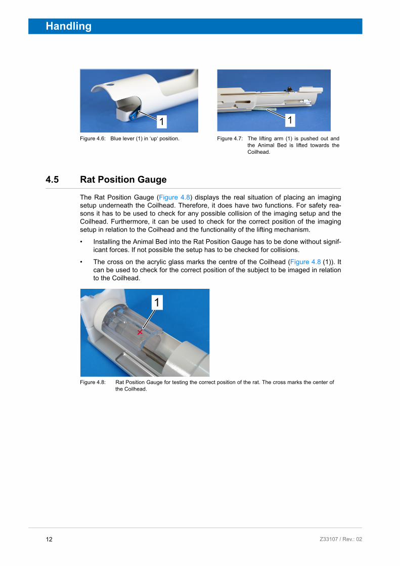
The lifting mechanism is controlled by the blue lever (Figure 4.4 (1)) at the end of the Animal Bed. When the blue lever is positioned in the ‘down‘ position the lifting arm (Fig-ure 4.5 ((1)) is counter-sunk within the Animal Bed (Figure 4.5). Moving the blue lever into the ‘up‘ position (Figure 4.6) lifts the front end of the Animal Bed by pushing out the lifting arm (Figure 4.7 (1)). The lifting mechanism is force limited.
The functionality of the lifting mechanism is only guaranteed if the Animal Bed is bal-anced. Therefore, the balancing has to be checked and probably adjusted for each measurement.
Figure 4.3: Balancing ring.
1. Position the fully equipped Animal Bed on a flat table and check for the balancing.
2. Loosen the screw (2) and move the ring (1) so that the Animal Bed is balanced.
3. Tight the screw again.
NOTICE
The blue lever has to be in the ‘down‘ position when installing and removing the Ani-mal Bed in/from the Rat Position Gauge and the MRI system!
Figure 4.4: Blue lever (1) fixed in ‘down‘ position. Figure 4.5: The lifting arm (1) counter-suck in the Animal Bed.
11 7 / Rev.: 02
Handling
4.5 Rat Position Gauge
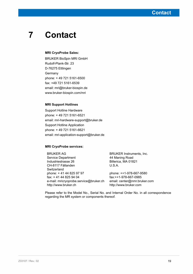
The Rat Position Gauge (Figure 4.8) displays the real situation of placing an imaging setup underneath the Coilhead. Therefore, it does have two functions. For safety rea-sons it has to be used to check for any possible collision of the imaging setup and the Coilhead. Furthermore, it can be used to check for the correct position of the imaging setup in relation to the Coilhead and the functionality of the lifting mechanism.
• Installing the Animal Bed into the Rat Position Gauge has to be done without signif-icant forces. If not possible the setup has to be checked for collisions.
• The cross on the acrylic glass marks the centre of the Coilhead (Figure 4.8 (1)). It can be used to check for the correct position of the subject to be imaged in relation to the Coilhead.
.
Figure 4.6: Blue lever (1) in ‘up‘ position. Figure 4.7: The lifting arm (1) is pushed out and the Animal Bed is lifted towards the Coilhead.
Figure 4.8: Rat Position Gauge for testing the correct position of the rat. The cross marks the center of the Coilhead.
12 Z33107 / Rev.: 02

Z3310
Handling
4.6 Handling of the Bio Animal Bed Rat Cryo on the MRI System
Installation
1. Check for the correct installation of the CryoProbe in the MRI system before install-ing the Animal Bed.
2. To install the Animal Bed into the MRI system, move the blue lever into the ‘down‘ position.
3. The Animal Bed has to be moved into the MRI system from the patient end.
4. Constantly check for the correct rotation of the Animal Bed while moving it into the MRI system until the mechanical stop is reached.
5. Put the blue lever into the ‘up‘ position.
Removal
1. Put the blue lever into the ‘down‘ position.
2. Carefully remove the Animal Bed from the MRI system. Again check for the correct rotation of the Animal Bed.
NOTICE
Before installing a new imaging setup into the MRI system, any possible collision of the setup with the Coilhead has to be checked by using the Rat Position Gauge!
The CryoProbe has to be installed in the MRI system before the Animal Bed can be installed!
Installation and removal of the Animal Bed is only possible when the blue lever is in the ‘down‘ position!
13 7 / Rev.: 02

Handling
14 Z33107 / Rev.: 02

Z3310
5 Material & Cleaning
5.1 Material
The half shell of the Animal Bed system is made of PEEK. PEEK is normal fire-proof according to the guidelines of DIN 4102 B2. The maximum operating temperature should not exceed 75°C air temperature, also without mechanical load.
The Animal Bed is a highly complex and delicate accessory. It should be handled with great care. Do not drop or bend the Animal Bed and avoid impact with hard objects which may scratch or damage it.
5.2 Cleaning
For cleaning, neutral antistatic plastic cleaners or desinfection cleaners are recom-mended. Commercial household cleaners without polishing agents can be used.
Never use cleaners that contain organic solvents such as benzene, acetone or chlor-inated hydrocarbons. Also, alcohol cleaners in high concentration must not be used, otherwise the Animal bed system can be severely damaged.
NOTICE
Cleaner containing organic solvents or alcohol can damage the Animal bed.
Therefore:
• Use only neutral antistatic plastic cleaners or disinfection cleaners. Commercial household cleaners without polishing agents can also be used.
157 / Rev.:02

Material & Cleaning
16 Z33107 / Rev.:02

Z3310
Scope of Supply
6 Scope of Supply
6.1 Spare parts for Animal Bed Z140780
Figure 6.1: Explosion view of the Animal Bed showing the spare parts which can be separately ordered as listed in Table 6.1 on page 17.
Scope of sup-ply in Fig. 6.1
Part number Description Material
1 Z151109 Ear plug holder Type 1 low POM black
Z151110 Ear plug holder Type 2 POM white
2 28477 Screw M3 x 4 PA (polyamids)
3 Z113768 Ear plug POM white
4 Z113764 Guide rail left 180° flex long PEEK
5 Z151112 Toothbar PET-C
6 Z151108 Respiration mask rat PEEK
7 Z113763 Headless screw M3 PEEK
8 Z151111 Extension toothbar red PA
9 23025 O-rings 15 x 1 PMMA
10 Z113765 Guide rail right 180° flex long PEEK
11 T10690 Heating cover
Z113800 Screw driver
Z33107 Animal Bed Rat Cryo Manual
Table 6.1: Parts for Animal Bed are shown in Figure 6.1. Please check with Figure 6.1 and the table what has to be replaced or is missing.
17 7 / Rev.: 02

Scope of Supply
18 Z33107 / Rev.: 02
Z3310
Contact
7 Contact
MRI CryoProbe Sales:
BRUKER BioSpin MRI GmbH
Rudolf-Plank-Str. 23
D-76275 Ettlingen
Germany
phone: + 49 721 5161-6500
fax: +49 721 5161-6539
email: [email protected]
www.bruker-biospin.com/mri
MRI Support Hotlines
Support Hotline Hardware
phone: + 49 721 5161-6521
email: [email protected]
Support Hotline Application
phone: + 49 721 5161-6621
email: [email protected]
MRI CryoProbe services:
Please refer to the Model No., Serial No. and Internal Order No. in all correspondence regarding the MR system or components thereof.
BRUKER AGService DepartmentIndustriestrasse 26CH-8117 FällandenSwitzerlandphone: + 41 44 825 97 97fax: + 41 44 825 94 04e-mail: [email protected]://www.bruker.ch
BRUKER Instruments, Inc.44 Maning RoadBillerica, MA 01821U.S.A.
phone: ++1-978-667-9580fax:++1-978-667-0985email: [email protected]://www.bruker.com
19 7 / Rev.: 02

Contact
20 Z33107 / Rev.: 02

