ankit final report
TRANSCRIPT
Variable Axis Hybrid Layered
Manufacturing
Thesis
Submitted in partial fulfillment of the requirements for the degree of
Master of Technology
by
Ankit Desai (133100069)
under the supervision of
Prof. K. P. Karunakaran
Department of Mechanical Engineering Indian Institute Of Technology, Bombay
June 2015

Declaration
I declare that this thesis represents my own ideas in my own words and where
other’s ideas or words have been included, I have adequately cited and references
the original sources. I also declare that I have adhered to all principles of academic
honesty and integrity and have not misrepresented or fabricated or falsified any
idea/data/fact/source in my submission. I understand than any violation of the
above will be cause for disciplinary action by the institute and can also evoke penal
action from the source which has thus not been properly cited or from whom proper
permission has not been taken when needed.
Ankit Desai
M.Tech Student
Roll No. 133100069
Approval Sheet
This Thesis entitled ‘Variable Axis Hybrid Layered Manufacturing’ by Ankit
Desai (Roll No. 133100069) is approved for the final submission of M.Tech Project
at the Department of Mechanical Engineering, IIT Bombay.
Examiners
________________________
________________________
Supervisor
________________________
Chairman
________________________
Date:____________
Place:____________
i
Abstract
Hybrid Layered Manufacturing (HLM) is an Additive Manufacturing (AM) process of metals
which combines the benefits of both additive and subtractive manufacturing techniques. The
integration is in such a manner that the weld-deposition can act as an additional feature to
an existing CNC machine without disturbing its other capabilities . The deposition of metal
according to the generated toolpath is done using a Gas Metal Arc Welding (GMAW) gun.
After the deposition of near net shape, the machining process is used for achieving the
dimensional accuracy.
The main goal of the present work is to solve the current issues in HLM and increase the
capabilities. Like any other AM processes, HLM proceeds in a layer by layer manner. CAD
model of the desired component is sliced into thin layers and toolpath is generated for each
layer. In HLM process, no support material is used for deposition of undercuts/overhang
features. The need for support mechanism is eliminated using 5-Axis deposition. The featured
based deposition AM can fabricate the complex geometries by 5-Axis HLM process. Also the
implementation of this method can save material and time during deposition. The capability
of this novel method is proved by an example of complex IC-7 housing component.
Instead of starting the deposition from base metal plate and remove it by machining after
deposition, if we use the plate as integral substrate then it increases the strength of the
component. Also the efficiency of the AM process increases if we get the best engagement
of the substrate with the component by reducing the wastage material. New deposition
method with integral substrate has been introduced and discussed in detail with the example
of turbine blade.
In CNC machine the available workspace for deposition is reduced because of offset in
mounting the gun. For tool steel and exotic materials (Ni and Tin alloys), preheating, stress
relieving and inspection after every deposition are required. Conceptual and final design for
the integrated multi-station HLM has been suggested which can be resolve the existing
issues.
The residual stresses are one of the main issue in HLM process which can be overcome
by mechanical pining process. A pneumatic hammer has been used for this purpose which is
modified as per the requirement and retrofitted on the same CNC machine. A model has been
developed to predict the hammer frequency and compared with the measured frequency by
experiments. The main purpose of calculating the frequency is to find out the optimal feed
rate of hammer.

ii
GTAW process can give a better quality of bead as compare to GMAW process. Hence
this process has been explored in this work and experiment are performed for different
process parameters. The experiments are divided into three major parts: Single bead
experiments, Multi bead experiments and Multi layer experiments.
Keywords: Rapid Manufacturing, Rapid Prototyping, Hybrid Layered Manufacturing,
Feature Based Slicing, Integral Substrate, Multi-Station HLM, 5-axis, Cold working,
GMAW, GTAW
ii
Contents
Abstract i
Contents ii
List of Figures iv
List of Tables vii
1. Introduction
1.1 Rapid Manufacturing 1-1
1.1.1 Laser-based AM processes 1-4
1.1.2 Electron beam-based AM processes 1-6
1.1.3 Arc-based AM processes 1-7
1.2 Hybrid Layered Manufacturing 1-10
1.2.1 Modes of HLM 1-11
1.2.2 Capabilities of HLM 1-14
1.2.3 Software feature required 1-16
1.2.4 Need for DelCAM 1-17
1.2.5 Existing issues with HLM 1-18
1.3 Problem Definition 1-19
1.4 Organization of the Report 1-19
2. Variable Axis Deposition
2.1 Introduction 2-1
2.2 Planar Deposition 2-1
2.2.1 3-axis deposition 2-1
2.2.2 5-axis deposition 2-3
2.3 Featured Based Deposition 2-9
2.3.1 Implementation procedure for a complex part 2-10
iii
2.4 Summary 2-19
3. Integral Substrate Method
3.1 Introduction 3-1
3.2 Methodology 3-1
3.2.1 Maximum consumable volume of substrate 3-1
3.2.2 Slicing and near net CAD model 3-4
3.2.3 Toolpath generation 3-5
3.3 Implementation Details in a CAM Package 3-6
3.4 Result Analysis 3-8
3.5 Summary 3-11
4. An Integrated Multi-Station HLM
4.1 Introduction 4-1
4.2 Need for Integrated Multi-Station HLM 4-1
4.3 Facilities in Integrated Multi-Station HLM 4-2
4.3.1 Preheating / TIG deposition 4-2
4.3.2 MIG deposition 4-3
4.3.3 Face milling 4-4
4.3.4 Inspection 4-4
4.3.5 Cold working 4-5
4.4 Proposed Conceptual Design of Integrated Multi-Station HLM 4-6
4.5 Final Design of Integrated Multi-Station HLM 4-8
4.5.1 Advantages of lead screw mechanism over scissor lift 4-11
4.6 Summary 4-11
5. In-situ CNC Integrated Pneumatic Hammer
5.1 Introduction 5-1
5.2 Need of Pneumatic Hammer in HLM 5-1
5.3 Principle of Operation of a Pneumatic Hammer 5-2
5.3.1 Air pass operations in pneumatic hammer 5-3
iv
5.4 Experimental Setup on CNC Machine 5-5
5.4.1 Process parameters for pneumatic hammer peening 5-6
5.5 Frequency Measurement of Pneumatic Hammer 5-7
5.6 Advantage and Limitation of the Pneumatic Hammer Peening 5-11
5.7 Summary 5-12
6. GTAW for Hybrid Layered Manufacturing
6.1 Introduction 6-1
6.2 Single Bead Experiments 6-2
6.3 Multi Bead Experiments 6-5
6.4 Multi Layer Experiments 6-5
6.4.1 Hardness test 6-6
6.4.2 Microstructure analysis 6-6
6.4.3 X-ray results 6-9
6.5 Directional Problem in GTAW Deposition 6-10
6.6 Summary 6-11
7. Conclusion and Future Scope
7.1 Conclusion 7-1
7.2 Future Scope 7-2
References R-1
iv
List of Figures
1.1 Rapid Prototyping Process Flow 1-2
1.2 Classification of Rapid Manufacturing Technologies 1-3
1.3 Laser Engineered Net Shaping (LENS) 1-5
1.4 Boeing components made using LAM 1-6
1.5 Gas Metal Arc Welding process 1-8
1.6 Schematic of CMT equipment 1-10
1.7 3-Axis HLM - CNC Machine and the welding gun retrofitment 1-12
1.8 5-Axis HLM - CNC Machine and the welding gun retrofitment 1-13
1.9 Capabilities of HLM 1-14
1.10 CAD model of the Impeller 1-15
1.11 Impeller: (a) Near net shape (b) after finish-machining 1-16
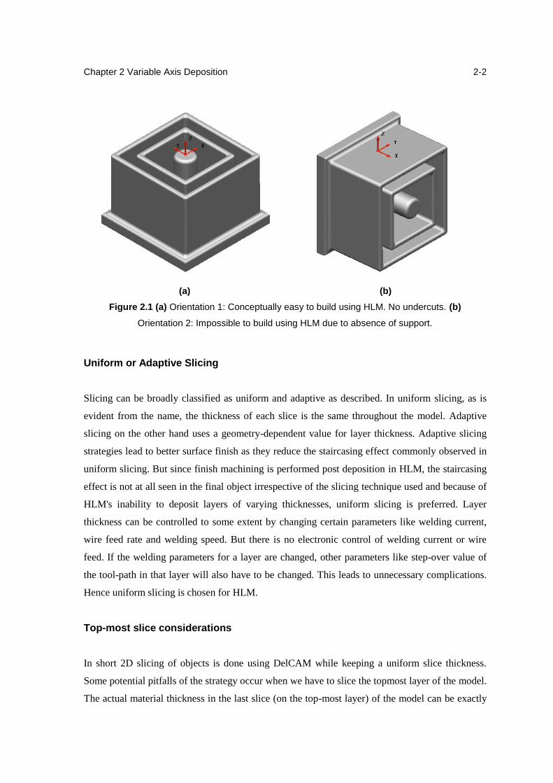
2.1 (a) Orientation 1: Conceptually easy to build using HLM. (b) Orientation
2: Impossible to build using HLM due to absence of support.
2-2
2.2 Slicing - layer thickness adjustment for locally topmost slices: (a)
original solid model, (b) sliced model with constant layer thickness, and
(c) sliced model with adjusted layer thickness
2-3
2.3 (a) Normal position - Greater overhang. Droplet falls off. (b) Tilted
position - Overhang in line with the torch. The table is tilted to capture
the falling droplet
2-4
2.4 Torch vector computed as a cross product of the normal and direction
vectors
2-5
2.5 (a) Object to be sliced. Total Z-height = 60mm (b) After slicing is
complete. The loops in all slice layers combined
2-7
2.6 (a) The 21 slice planes. (b) An intermediate slice 2-7
2.7 (a) The loops in two close slices (b) Re-pointed loops 2-8
2.8 The ruled surfaces between the two slices. The short yellow lines depict
the torch vector
2-8
v
2.9 (a) An example for sharp overhang in part (b) Planar slicing of the part 2-9
2.10 (a) Sub-volume 1 that can be built in +Z direction (b) Sub-volume 2 that
can be built in radial direction
2-10
2.11 Different view of a complex IC-7 housing part 2-11
2.12 Sharp overhang in the part while deposition is taking place in +z
direction
2-11
2.13 Deposited few planar layers and supporting cap for the overhang portion 2-12
2.14 Identification of the base cylinder 2-12
2.15 Decomposed complex part into four sub-volumes 2-13
2-16 (a) 3-Axis Slicing of the base cylinder for deposition (b) An intermediate
slice with toolpath (contour parallel strategy)
2-14
2.17 (a) Selection of the base surface (b) Adding the selected layer into
another level
2-15
2.18 (a) Scaling the base surface (b) Copy of offset surfaces 2-15
2.19 (a) Complete slicing of the part (b) Selected slice to intersect with the
part (c) An intermediate slice with the intersection
2-16
2.20 (a) Strategy selection (b) Generate of tool path in a conformal slice 2-17
2.21 (a) Upper cylinder on top of radial part (b) 3-Axis planar slice of the
upper cylinder
2-18
3.1 (a) CAD model of the turbine blade, (b) The integral substrate at centre
of component
3-2
3.2 Best position finding 3-3
3.3 (a) Best position of the substrate with work piece at z=-1 (b) Volume of
component covered by substrate
3-3
3.4 (a) Sliced component by Gati-Nirman (b) Sliced component with
substrate (substrate slices are removed)
3-4
3.5 (a) Contours on each Slice of the component from both face of the
substrate (b) Extruded volume of the contours on each slice (near net
CAD model)
3-5
3.6 Toolpath generation for entire component by Gati-Nirman 3-5
vi
3.7 Contour parallel toolpath (a) 1st layer with 1 contour (b) 8th layer with 4
contour (c) 1st extruded volume (d) 8th extruded volume
3-6
3.8 Flow chart for generalized CAM package implementation 3-7
3.9 Bounding box calculation for subtractive process 3-8
3.10 Central consumable substrate 3-9
3.11 Deposited layers of turbine blade by integral substrate method 3-11
4.1 Maximum temperatures (K) during the deposition of the first track for the
preheated and non-preheated substrates
4-3
4.2 Defected parts (a) Porosity defect, (b) Unfilled area 4-4
4.3 Current setup for shot peening hammer 4-6
4.4 Conceptual Design of Multi-Station HLM 4-6
4.5 Table with 4-axis motion 4-7
4.6 A scissor lift to achieve the Z motion 4-8
4.7 (a) and (b) Final Design of Multi-Station HLM 4-9
4.8 Deposition station with hydraulic arrangement 4-9
4.9 (a) Base with slots for lead screw and guide rods (b) Ground with slotting
for installing
4-10
5.1 (a) Different components of in-situ pneumatic hammer (b) CAD model of
pneumatic hammer (c) In-situ CNC integrated pneumatic hammer
5-2
5.2 Different air pass operations 5-5
5.3 (a) and (b) Design option of housing and clamping for hammer on CNC
machine, (c) Drilled holes to attach with machine, (d) Circular track to
provide circular motion
5-6
5.4 (a) Aluminum long plate for marking the indent (b) Indentation marks on
plate at different pressure
5-7
5.5 (a) Cross section view of the air cylinder of the pneumatic hammer (b)
Free body diagram of piston
5-8
5.6 (a) Graph of displacement vs time for 1 bar air pressure (b) Zoom portion
of the same graph
5-9
5.7 (a) Graph of displacement vs time for 3.5 bar air pressure (b) Zoom
portion of the same graph
5-10
vii
5.8 Graph for comparison of the experimental and predicted frequency 5-10
5.9 Graph for diameter of indentation at different pressure 5-11
6.1 Optimal Nozzle and wire position for 1.2 mm diameter 6-2
6.2 Image obtained from the stereo microscope of the single bead cut section 6-3
6.3 Results of penetration, width and height for single weld bead for different
wire feeds
6-4
6.4 Layer thickness with stepover increment 6-5
6.5 (a) Microstructure of top layer (grain size 4.39 µm) (b) Microstructure of
bottom layer (grain size 8.9 µm) (c) Microstructure of middle layers (grain
size 5.33 µm and 6.75 µm)
6-8
6.6 X-ray results of the multi layer block (a) from top surface (b) from side 6-9
6.7 (a) Standoff distace 5 mm which is optimal (b) standoff distance 7mm 6-10
6.8 Height and width of circular weld bead at different points 6-10
vii
List of Tables
1.2 Various deposition-based RM processes according the energy source used 1-4
1.3 Specifications of the weld-deposition unit 1-10
3.1 Volume of the component covered by the substrate at different level 3-2
3.2 Extruded volume of each layer 3-9
5.1 Comparison of the experimental and predictable frequency for different
pressure values
5-10
6.1 Parameters influencing the experiments 6-1
6.2 Results of hardness test on the sample 6-6
6.3 Grain size of different layers 6-9
Chapter 1
Introduction
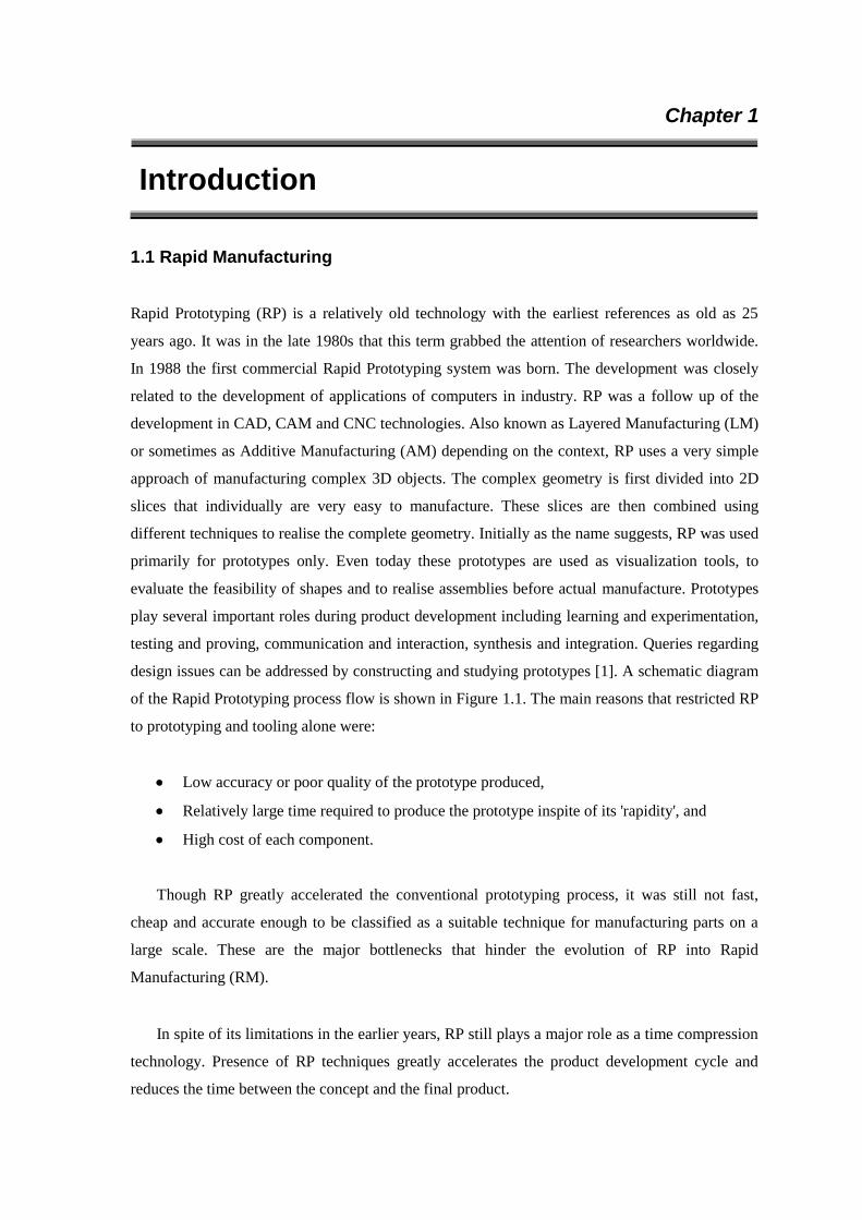
1.1 Rapid Manufacturing
Rapid Prototyping (RP) is a relatively old technology with the earliest references as old as 25
years ago. It was in the late 1980s that this term grabbed the attention of researchers worldwide.
In 1988 the first commercial Rapid Prototyping system was born. The development was closely
related to the development of applications of computers in industry. RP was a follow up of the
development in CAD, CAM and CNC technologies. Also known as Layered Manufacturing (LM)
or sometimes as Additive Manufacturing (AM) depending on the context, RP uses a very simple
approach of manufacturing complex 3D objects. The complex geometry is first divided into 2D
slices that individually are very easy to manufacture. These slices are then combined using
different techniques to realise the complete geometry. Initially as the name suggests, RP was used
primarily for prototypes only. Even today these prototypes are used as visualization tools, to
evaluate the feasibility of shapes and to realise assemblies before actual manufacture. Prototypes
play several important roles during product development including learning and experimentation,
testing and proving, communication and interaction, synthesis and integration. Queries regarding
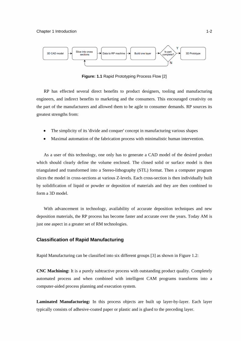
design issues can be addressed by constructing and studying prototypes [1]. A schematic diagram
of the Rapid Prototyping process flow is shown in Figure 1.1. The main reasons that restricted RP
to prototyping and tooling alone were:
Low accuracy or poor quality of the prototype produced,
Relatively large time required to produce the prototype inspite of its 'rapidity', and
High cost of each component.
Though RP greatly accelerated the conventional prototyping process, it was still not fast,
cheap and accurate enough to be classified as a suitable technique for manufacturing parts on a
large scale. These are the major bottlenecks that hinder the evolution of RP into Rapid
Manufacturing (RM).
In spite of its limitations in the earlier years, RP still plays a major role as a time compression
technology. Presence of RP techniques greatly accelerates the product development cycle and
reduces the time between the concept and the final product.
Chapter 1 Introduction
1-2
Figure: 1.1 Rapid Prototyping Process Flow [2]
RP has effected several direct benefits to product designers, tooling and manufacturing
engineers, and indirect benefits to marketing and the consumers. This encouraged creativity on
the part of the manufacturers and allowed them to be agile to consumer demands. RP sources its
greatest strengths from:
The simplicity of its 'divide and conquer' concept in manufacturing various shapes
Maximal automation of the fabrication process with minimalistic human intervention.
As a user of this technology, one only has to generate a CAD model of the desired product
which should clearly define the volume enclosed. The closed solid or surface model is then
triangulated and transformed into a Stereo-lithography (STL) format. Then a computer program
slices the model in cross-sections at various Z-levels. Each cross-section is then individually built
by solidification of liquid or powder or deposition of materials and they are then combined to
form a 3D model.
With advancement in technology, availability of accurate deposition techniques and new
deposition materials, the RP process has become faster and accurate over the years. Today AM is
just one aspect in a greater set of RM technologies.
Classification of Rapid Manufacturing
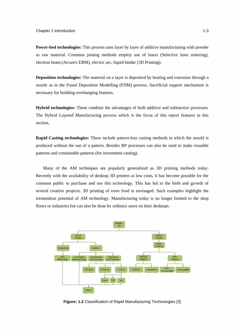
Rapid Manufacturing can be classified into six different groups [3] as shown in Figure 1.2:
CNC Machining: It is a purely subtractive process with outstanding product quality. Completely
automated process and when combined with intelligent CAM programs transforms into a
computer-aided process planning and execution system.
Laminated Manufacturing: In this process objects are built up layer-by-layer. Each layer
typically consists of adhesive-coated paper or plastic and is glued to the preceding layer.
Chapter 1 Introduction
1-3
Power-bed technologies: This process uses layer by layer of additive manufacturing with powder
as raw material. Common joining methods employ use of lasers (Selective laser sintering),
electron beam (Arcam's EBM), electric arc, liquid binder (3D Printing).
Deposition technologies: The material on a layer is deposited by heating and extrusion through a
nozzle as in the Fused Deposition Modelling (FDM) process. Sacrificial support mechanism is
necessary for building overhanging features.
Hybrid technologies: These combine the advantages of both additive and subtractive processes.
The Hybrid Layered Manufacturing process which is the focus of this report features in this
section.
Rapid Casting technologies: These include pattern-less casting methods in which the mould is
produced without the use of a pattern. Besides RP processes can also be used to make reusable
patterns and consumable patterns (for investment casting).
Many of the AM techniques are popularly generalized as 3D printing methods today.
Recently with the availability of desktop 3D printers at low costs, it has become possible for the
common public to purchase and use this technology. This has led to the birth and growth of
several creative projects. 3D printing of even food is envisaged. Such examples highlight the
tremendous potential of AM technology. Manufacturing today is no longer limited to the shop
floors or industries but can also be done by ordinary users on their desktops.
Figure: 1.2 Classification of Rapid Manufacturing Technologies [3]
Chapter 1 Introduction
1-4
In additive manufacturing using deposition, the metal is deposited only in the required regions
in a layer-by-layer manner. The material can be fed either in the form of wire or powder. The
deposition technologies employ laser, electron beam or electric arc as the sources of thermal
energy for melting the metal, in the order of their present popularity. Table 1.2 lists various
existing technologies in each category. These three groups of deposition processes are discussed
further in the following sub-sections.
Table 1.1 Various deposition-based RM processes according the energy source used [4]
Energy Source Name
Laser
Direct Metal Deposition (DMD)
Directed Light Fabrication (DLF)
Laser Additive Manufacturing (LAM)
Laser Aided Manufacturing Process (LAMP)
Laser Based Additive Manufacturing (LBAM)
Laser Based Direct Metal Deposition (LBDMD)
Laser Engineered Net Shaping (LENS)
Rapid Direct Metal Deposition
Electron Beam Electron Beam Freeforming
Arc
3D Micro Welding (3DMW)
3D Welding
3D Welding and Milling
Hybrid Layered Manufacturing (HLM)
Hybrid Plasma Deposition and Milling (HPDM)
Micro-Plasma Arc Welding (MPAW)
Shape Deposition Manufacturing (SDM)
1.1.1 Laser-based RM processes
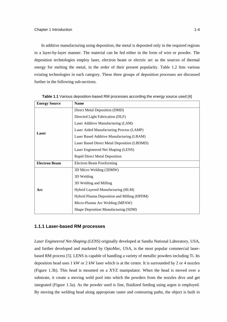
Laser Engineered Net-Shaping (LENS) originally developed at Sandia National Laboratory, USA,
and further developed and marketed by OptoMec, USA, is the most popular commercial laser-
based RM process [5]. LENS is capable of handling a variety of metallic powders including Ti. Its
deposition head uses 1 kW or 2 kW laser which is at the centre. It is surrounded by 2 or 4 nozzles
(Figure 1.3b). This head is mounted on a XYZ manipulator. When the head is moved over a
substrate, it create a moving weld pool into which the powders from the nozzles dive and get
integrated (Figure 1.3a). As the powder used is fine, fluidized feeding using argon is employed.
By moving the welding head along appropriate raster and contouring paths, the object is built in
Chapter 1 Introduction
1-5
layers. It permits usage of different powders through different nozzles with the ability to control
their flow rate independently. Thus, LENS is capable of building gradient objects.
(a) (b)
Figure 1.3 Laser Engineered Net Shaping (LENS) (a) Schematic of the LENS process (b) Wall-
shaped build in progress using the LENS process [6]
Directed Light Fabrication (DLF) developed at Los Alamos National Laboratory is also very
similar to LENS. Interestingly, it is designed as a retrofitment to an existing CNC machine,
similar to HLM process.
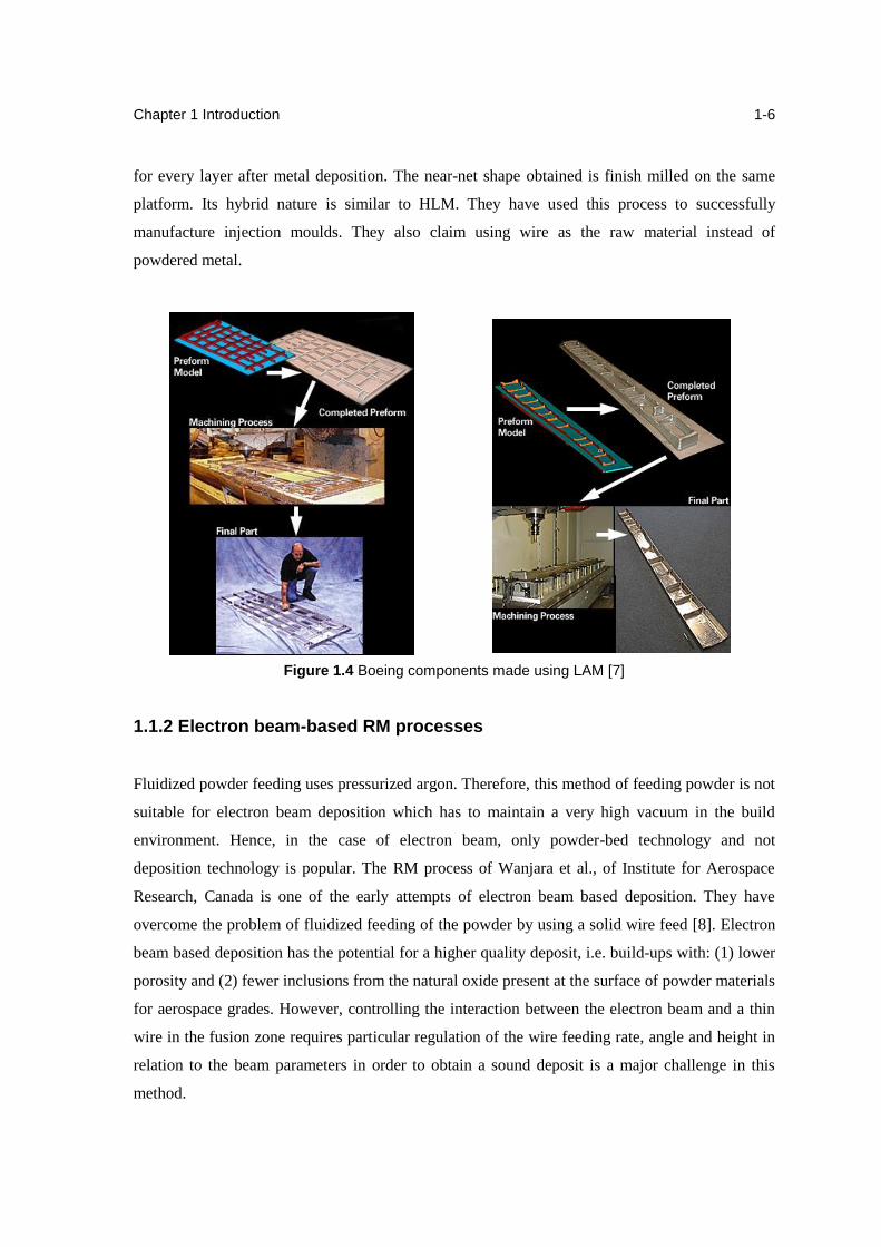
Laser Additive manufacturing (LAM), developed by AeroMet corp, USA is a similar RM
method aimed at producing large parts from reactive materials such as titanium for aerospace
applications. Preliminary work done by AeroMet indicates that the process is capable of
producing sound Ti-6Al-4V material with acceptable mechanical properties for a multitude of
aerospace applications [7]. They have also supplied non-critical Titanium components for Boeing
with significant success (Figure 1.4). The undercuts of the CAD model were suppressed and
suitable machining allowance was added. This near-net shape was built using an 18 kW laser on a
2.5 axis machine.
To overcome the height control problem and ensure accuracy without any need of feed-back
control, Choi et al., of Korea Institute of Science and Technology (KIST) introduced face milling
Chapter 1 Introduction
1-6
for every layer after metal deposition. The near-net shape obtained is finish milled on the same
platform. Its hybrid nature is similar to HLM. They have used this process to successfully
manufacture injection moulds. They also claim using wire as the raw material instead of
powdered metal.
Figure 1.4 Boeing components made using LAM [7]
1.1.2 Electron beam-based RM processes
Fluidized powder feeding uses pressurized argon. Therefore, this method of feeding powder is not
suitable for electron beam deposition which has to maintain a very high vacuum in the build
environment. Hence, in the case of electron beam, only powder-bed technology and not
deposition technology is popular. The RM process of Wanjara et al., of Institute for Aerospace
Research, Canada is one of the early attempts of electron beam based deposition. They have
overcome the problem of fluidized feeding of the powder by using a solid wire feed [8]. Electron
beam based deposition has the potential for a higher quality deposit, i.e. build-ups with: (1) lower
porosity and (2) fewer inclusions from the natural oxide present at the surface of powder materials
for aerospace grades. However, controlling the interaction between the electron beam and a thin
wire in the fusion zone requires particular regulation of the wire feeding rate, angle and height in
relation to the beam parameters in order to obtain a sound deposit is a major challenge in this
method.
Chapter 1 Introduction
1-7
1.1.3 Arc-based RM processes
Arc-based RM processes contains GTAW, GMAW and PAW. Some of the researcher combines
the GTAM and PAW. The GMAW is mainly use in RM lab which has been described in detail. A
novel freeform fabrication method named 3D Micro Welding (3DMW) has been developed using
an idea to combine freeform fabrication method with GTAW by researchers of Osaka University,
Japan [9-10]. When pulsed micro-arcs are emitted, the tip of a thin metal wire with a diameter of
0.1–0.3mm is fused and a micro metal bead is formed instantaneously. A fused bead is welded to
a metal substrate or previously formed beads. By continuing this process and building up hot
beads layer by layer under the control of CAD/CAM system, 3D metal objects can be produced. It
can be applied not only to titanium, but to other refractory metals such as tantalum, tungsten due
to the high dense energy beam of the micro arc. When two different thin metal wires such as Ti
and Ni, Ni and Al are fed alternately from the opposed spools, it is possible to build 3D complex
structures and components composed of their alloys or inter-metallic compounds [10].
KIST also has worked in GMAW based hybrid RM process. In fact, they had mounted on the
spindle head of the same CNC machine a laser torch and two GMAW torches [11]. Thus, this
platform could be used for both laser and arc deposition studies. The substrate plate is fixed on
top of a preheating fixture mounted on the machine table. Two different welding wire
sizes/materials are used in these torches. Use of different diameter wires permits the interior of the
layer to be filled fast by the thick wire and the periphery by the thin wire accurately. Face milling
is performed after depositing each layer. Although the layers may be deposited in uniform
thicknesses, face milling is used to obtain adaptive layers; however, this is at the expense of
material wastage. In milling operation, the top as well as the sides of the slice is machined to a
specified height and width before depositing new layer upon the previous one. This procedure is
repeated until the entire part is complete.
Direct Metal Deposition (DMD) developed at Southern Methodist University, USA is another
3D Welding process which uses Gas Tungsten Arc Welding (GTAW) instead of GMAW [12].
Although they used GMAW in the beginning, they subsequently shifted to GTAW as they found
it much more controllable process for deposition with fewer problems of sputtering, intensive
heating, smoke etc. They have also used variable polarity GTAW for rapid prototyping of
aluminium alloy.
Chapter 1 Introduction
1-8
Gas Metal Arc Welding
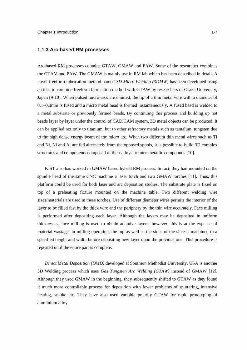
In Gas Metal Arc Welding (GMAW) a continuous and consumable wire electrode and a shielding
gas are fed through a welding torch. An electric arc established between the work piece and the
consumable wire electrode continuously melts the wire as it is fed into the weld puddle. The
molten pool is masked by the shielding gas.
Figure 1.5 Gas Metal Arc Welding process [13]
The arc, known as plasma, is a column of electrically and thermally excited gas atoms
and ionized metal vapours from the electrode material (Figure 1.5). This plasma is as hot
as 6,000°C. This intense heat causes the gas atoms in the arc to break into positive ions
and electrons. Electrons move from cathode to anode and the positive ions move from
anode to cathode. Although both AC and DC power can be used for arc welding, the most
preferred in GMAW is DC – either in continuous or pulse form.
Welding gas is used for shielding or masking the weld pool from atmospheric contamination
as well as to provide lower Ionization Potential (IP). Depending on the welding gas used, GMAW
may be known as Metal Inert Gas (MIG) or Metal Activated Gas (MAG) welding. In MIG
welding, the shielding gas is an inert gas like He or Ar or their mixture. MAG welding uses active
gases such as CO2, H2 and O2 and their mixture. When 100% CO2 is used, the MIG welding is
also known as CO2 welding.
Chapter 1 Introduction
1-9
CMT Pulsed DC with appropriate ramps is preferable to continuous DC as it gives stable arc
even at a lower mean current, thus reducing the heat input. However, in pulsed GMAW, the
operator is required to set the background current, peak current and their durations apart from the
parameters required to be controlled for successful operation in normal GMAW. As the
relationships among these parameters are too complex, setting their optimal values manually is
too difficult. This led to the development of synergic GMAW.
In synergic control, when an optimal combination of pulse parameters is set once for a given
wire feed rate and wire diameter, the system maintains the optimality for any change in the wire
feed rate. This implies that the burn off rate matches exactly the wire feed rate as dictated by the
initially set parameters. Thus it becomes a single knob control. The optimum applications
parameters are usually tuned into the welding machine by means of a microprocessor and a
software program. It is possible to achieve high torch speeds while keeping the spatter low
through synergic control. Accordingly, Fronius TPS-4000, a pulsed synergic GMAW was chosen.
This equipment, bought in 2001, was adequate for building monolithic objects. Building
composite objects requires two or more weld-deposition units. Therefore, Fronius TPS 2700
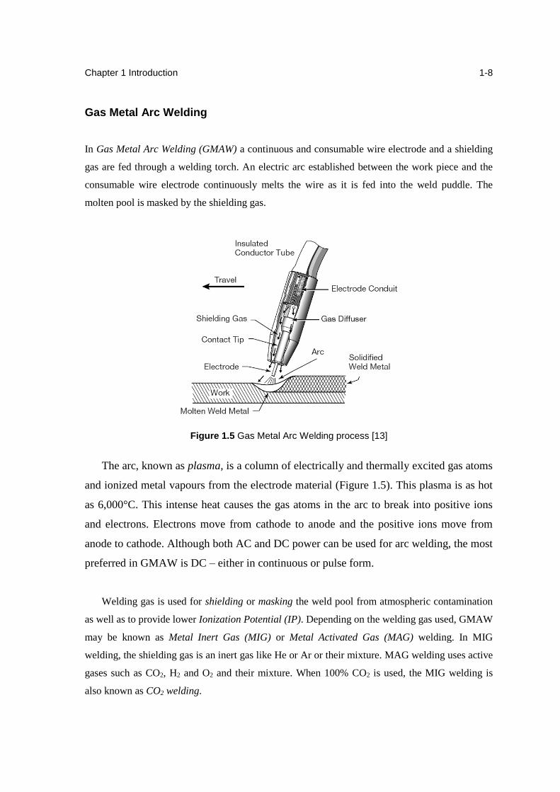
CMT, a next generation TPS GMAW machine was procured. Table 2.3 lists the specifications of
these two weld-deposition units.
Table 1.3 Specifications of the weld-deposition unit [4]
Feature CMT 2700
Make Fronius
Model TransPuls Synergic 2700 CMT
Torch Push-pull CMT type
Modes of operation Pulsed, synergic, CMT
Input power 3∅ 400V 50/60Hz 6.6 kVA
Welding current range 3-270 A
Open circuit voltage 50 V
Working voltage 14.2 – 27.5 V
Efficiency 87%
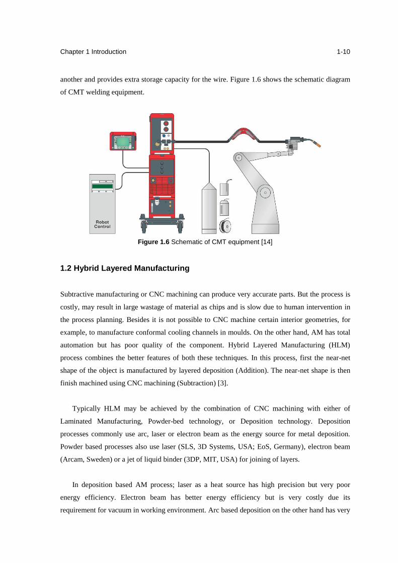
In CMT the wire feeder is located near the welding torch thus eliminating the error due to
slacking of the wire. This also gives greater control over the movement of the wire. A wire buffer
located between the wire feeder and the welding tip “decouples” the two wire-drives from one
Chapter 1 Introduction
1-10
another and provides extra storage capacity for the wire. Figure 1.6 shows the schematic diagram
of CMT welding equipment.
Figure 1.6 Schematic of CMT equipment [14]
1.2 Hybrid Layered Manufacturing
Subtractive manufacturing or CNC machining can produce very accurate parts. But the process is
costly, may result in large wastage of material as chips and is slow due to human intervention in
the process planning. Besides it is not possible to CNC machine certain interior geometries, for
example, to manufacture conformal cooling channels in moulds. On the other hand, AM has total
automation but has poor quality of the component. Hybrid Layered Manufacturing (HLM)
process combines the better features of both these techniques. In this process, first the near-net
shape of the object is manufactured by layered deposition (Addition). The near-net shape is then
finish machined using CNC machining (Subtraction) [3].
Typically HLM may be achieved by the combination of CNC machining with either of
Laminated Manufacturing, Powder-bed technology, or Deposition technology. Deposition
processes commonly use arc, laser or electron beam as the energy source for metal deposition.
Powder based processes also use laser (SLS, 3D Systems, USA; EoS, Germany), electron beam
(Arcam, Sweden) or a jet of liquid binder (3DP, MIT, USA) for joining of layers.
In deposition based AM process; laser as a heat source has high precision but very poor
energy efficiency. Electron beam has better energy efficiency but is very costly due its
requirement for vacuum in working environment. Arc based deposition on the other hand has very
Chapter 1 Introduction
1-11
high energy density, excellent efficiency and is the cheapest of all the three. Deposition method is
very suitable for gradient objects and the component produced is fully dense as melting is
involved [4]. Powder-based techniques on the other hand may require post-process densification
through hot isostatic pressing (HIP). However unlike power-based, deposition method also
requires an explicit sacrificial support mechanism.
IIT Bombay's HLM is a RM technology that uses pulsed synergic Gas Metal Arc Weld
(GMAW) deposition of metal layers. Use of arc welding for RM of metallic objects was first seen
in 3D welding developed at the University of Nottingham (UK) and in Shape Deposition
Manufacturing (SDM) developed at CMU (USA) (Spencer et al. 1998; Merz et al. 1994). CMU's
SDM also uses deposition and milling. Two materials are used for deposition - one for the actual
model and the other as a support material. Typically, steel models employ the use of copper as
support. In sections of the model where the normal are oriented downwards, the deposition of
support material is required. SDM requires path planning and 5-Axis kinematics [15].
In IITB, GMAW deposition based facility for HLM exists. Composite injection molds with
conformal cooling channels have been manufactured using this process. Presently procurement of
GTAW equipment is in progress and the facility should be in effect soon.
1.2.1 Modes of HLM
One can classify the HLM process into two major modes: 3-Axis HLM and continuous 5-Axis
HLM. A third mode may be classified as indexed 5-Axis.
3-Axis HLM
The main steps involved in 3-Axis HLM are:
1. The CAD model is sliced into layers depending on the layer thickness value. The
intersection contours are generated in each layer.
2. For each layer, first the outer contours are deposited by a 2.5D planar toolpath.
Chapter 1 Introduction
1-12
3. Then the interior area of each layer is filled again by a 2.5D area-filling toolpath. The
toolpath may be either direction-parallel or contour-parallel.
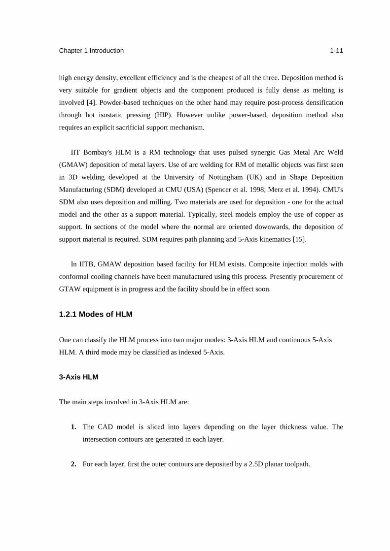
4. Finally the top face of the area is face-milled using a large diameter end-mill cutter to
maintain the Z-accuracy of the build. Then the next layer is created, and this process
continues until the top most layer is reached.
Figure: 1.7 3-Axis HLM - CNC Machine and the welding gun retrofitment [4]
Experimental Setup: The 3-Axis HLM system comprises of a 3-Axis CNC machining centre
Argo 1050P and a Fronius TPS 4000 welding equipment. The Fronius welding gun is fitted on the
tool post without interfering with any other functionality of the machine (Figure 1.7). To enable
switchover from machining mode to ArcHLM mode and vice-versa a DPDT switch is introduced
in the controller circuitry. The switch routes the output of the coolant control relay to the welding
input. When in the ArcHLM mode the coolant on/off machine codes (M08, M09) caused the
welding to switch on and off respectively. Thus the coolant is disabled when using HLM on the 3-
Axis CNC machine. Only a single material can be deposited thus there is no provision for a
support mechanism.
5-Axis HLM
5-Axis kinematics is used to alleviate the need for a support mechanism. The main steps involved
in 5-Axis HLM are:
Chapter 1 Introduction
1-13
1. The CAD model is sliced into layers depending on the layer thickness value. The
intersection contours are generated in each layer. The surface normal data at each point on
the contour is also stored along with the contours. Storage of normal distinguishes this
slicing strategy that is termed as 5-Axis slicing.
2. For each layer, first the outer contours are deposited by a 5-Axis deposition toolpath.
During this deposition the welding-gun is aligned along the torch vector at that point on
the contour.
3. The interior area of each layer is filled by deposition by a simple 2.5D area-filling
toolpath as in the case of 3-Axis deposition.
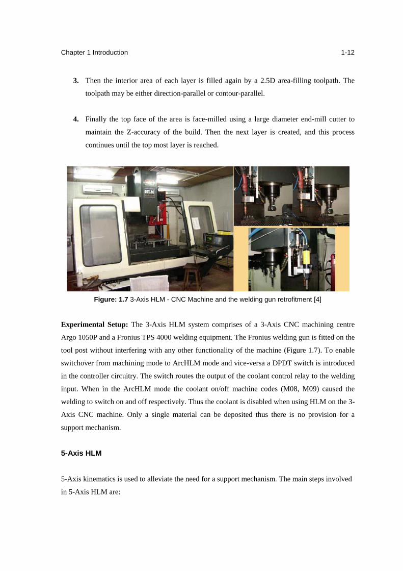
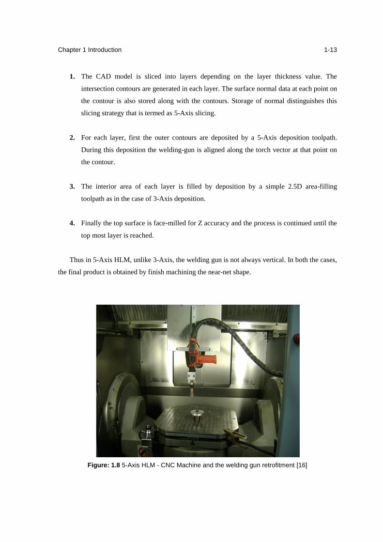
4. Finally the top surface is face-milled for Z accuracy and the process is continued until the
top most layer is reached.
Thus in 5-Axis HLM, unlike 3-Axis, the welding gun is not always vertical. In both the cases,
the final product is obtained by finish machining the near-net shape.
Figure: 1.8 5-Axis HLM - CNC Machine and the welding gun retrofitment [16]
Chapter 1 Introduction
1-14
Experimental Setup: Any existing CNC machine can be modified with suitable retrofitment to
transform it into a HLM system without altering its original capabilities. The new 5-Axis HLM
system uses a 5-Axis Hermle C30U CNC machine along with the Fronius welding equipment
allowing both deposition and finish machining to be performed using all five axes. (Figure: 1.8).
Since the 5-Axis CNC has additional machine-code controlled relays the need for a mode-
changing switch was eliminated. Thus the machine is capable of both simultaneous subtractive
and additive manufacturing without any hardware reconfiguration and switching. This opens up
avenues to manufacture extremely complex components also. In fact the presence of additional
relays allows the possibility of controlled multiple material deposition. Thus we can have an
independent support mechanism and also manufacture objects with functional gradient of
material.
1.2.2 Capabilities of HLM
This hybrid route saves both time and cost by eliminating the need for roughing operation of a
purely subtractive process thus conserving material. The material is deposited only as per
requirement with only a slight allowance for finishing. The NC programming effort is also
reduced as the tool-paths to be generated for the deposition are planar and often simpler
depending on the strategy employed. As the object made is dense, it can be used functionally
rather than just as a prototype.
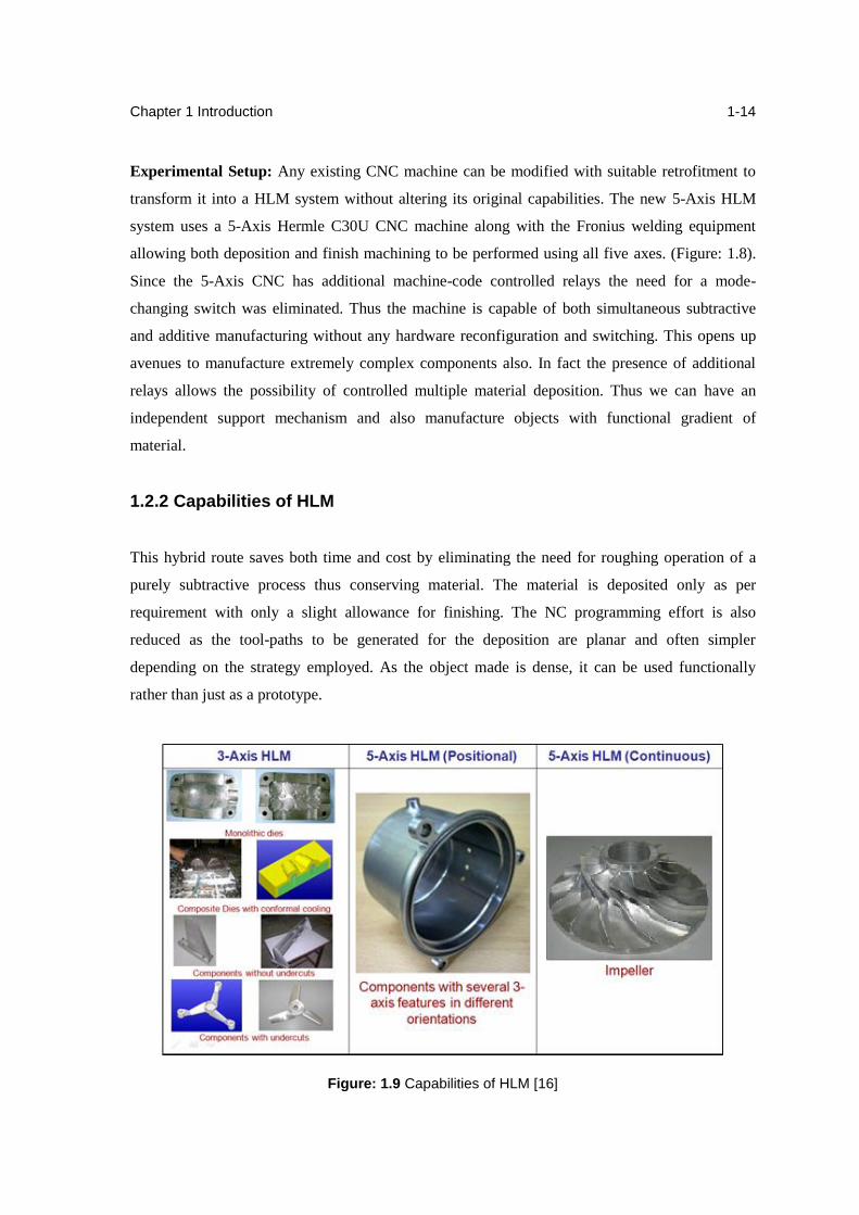
Figure: 1.9 Capabilities of HLM [16]
Chapter 1 Introduction
1-15
There are several prototyping, tooling and end-product manufacturing applications of GMAW
HLM that have already been realised. A summary of the capabilities of HLM is depicted in the
case studies shown in Figure 1.9. Using 3-Axis HLM alone the following have already been
manufactured:
Monolithic dies: Egg template of a Refrigerator
Dies with conformal cooling channels: Triangular cooling ducts in objects
Composite objects: Composite mould for rear light holder of a Bajaj Bike
Components without undercuts: Tall Al part for the Segmented Object Manufacturing
Machine
Components with undercuts: Monolithic Al-Si5 propeller
Using positional 5-Axis HLM components have been manufactured with several 3-Axis
features in different orientations. Example of a product of positional 5-Axis HLM is the
Aluminium casing for a pressure cooker.
Using continuous 5-Axis HLM complicated components such as impellers, blisks can also be
manufactured. This is especially useful for components with high overhang which cannot be
manufactured on 3-Axis machines. One of the greatest drawbacks of the HLM process is the
absence of support material. But it has been overcome to a large extent by the 5-Axis method.
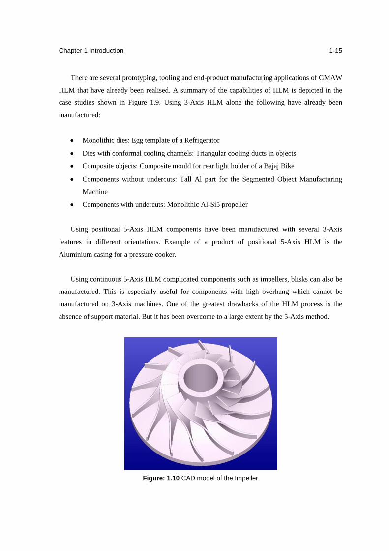
Figure: 1.10 CAD model of the Impeller
Chapter 1 Introduction
1-16
As an exercise to demonstrate the 5-Axis HLM process to manufacture a complex geometric
component an impeller was manufactured. Manufacture is possible by CNC machining it out of a
cylindrical block. But as stated earlier it is a time consuming process and results in wastage of a
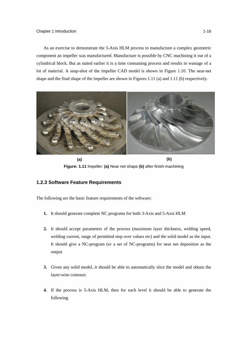
lot of material. A snap-shot of the impeller CAD model is shown in Figure 1.10. The near-net
shape and the final shape of the impeller are shown in Figures 1.11 (a) and 1.11 (b) respectively.
(a)
(b)
Figure: 1.11 Impeller: (a) Near net shape (b) after finish-machining
1.2.3 Software Feature Requirements
The following are the basic feature requirements of the software:
1. It should generate complete NC programs for both 3-Axis and 5-Axis HLM
2. It should accept parameters of the process (maximum layer thickness, welding speed,
welding current, range of permitted step over values etc) and the solid model as the input.
It should give a NC-program (or a set of NC-programs) for near net deposition as the
output
3. Given any solid model, it should be able to automatically slice the model and obtain the
layer-wise contours
4. If the process is 5-Axis HLM, then for each level it should be able to generate the
following
Chapter 1 Introduction
1-17
5-Axis toolpath of the outer contour with the welding gun aligned along the torch
vector
2.5-Axis area-filling toolpath that will fill the entire area inside the outer contour. The
area filling toolpath may be of any type - direction parallel (raster), contour parallel or
fractal based
5. If the process is 3-Axis HLM, then for each level it should be able to generate the
following
2.5-Axis toolpath of the outer contour with the welding gun aligned along the vertical
2.5-Axis area-filling toolpath that will fill the entire area inside the outer contour. The
area filling toolpath may be of any type - direction parallel (raster), contour parallel or
fractal based
1.2.4 Need for DelCAM
With a view to completely automate the near-net shape generation process, it is of paramount
importance that the deposition path of each layer is flawless. Hence the possibility of using a
professional CAM package for generating HLM toolpaths was explored. All conventional CAM
packages generate toolpaths for CNC machining. Professional CAM software for deposition are
rare. The challenge is in making the machining tool-paths double up as tool-paths for AM.
DelCAM's PowerMILL (CAM) and PowerSHAPE (CAD) are used for HLM. Use of PowerMILL
provides specific advantages over the existing HLM software system Gati. They are:
1. Proven functions: PowerMILL is a widely used software with proven toolpath generation
capabilities. It has several machining strategies including 2D strategies for slice area
clearance, which with certain changes can be used for the deposition toolpath.
2. In-built post processing: This reduces the hassles in generating the final NC program for
deposition and is irrespective of the CNC machine or controller used. Using DelCAM the
HLM software does not remain machine specific.
Chapter 1 Introduction
1-18
3. Integrated package for Addition and Subtraction: PowerMILL generates 5-Axis toolpaths.
Hence 5-Axis HLM and finish machining are also possible with this software. This is a
welcome change in terms of convenience as compared to the earlier situation when two
different softwares were used for deposition and finishing.
4. Smooth geometries: PowerMILL and PowerSHAPE work with smooth geometries.
Consequently the accuracy of the deposition toolpath along the contours is better.
1.2.5 Existing Issues with HLM
1. Gati-Nirman is an existing software developed in-house specifically for the HLM process
for slicing and then toolpath is generated in PowerMILL. The toolpath for planar slicing
can be generated and component can be produced by 3-axis and 5-axis. But there is no
such method for produce toolpath for continues 5-axis conformal slicing.
2. The base metal plate has been used for deposition which was removed by end milling
after near net shape part is formed. Due to this, difficulties have been occurred in re-
clamping and also base material is wasted which reduced efficiency of the HLM process.
3. Present HLM has only one station where deposition using GMAW and face milling is
done. Since the spindle axis and torch axis are apart by about 250 mm, this much traverse
is lost.
4. Currently there is no inspection system by which we can check the component defects
after each layer. Due to this, many times we come to know about defects after completing
whole part.
5. Due to thermal cycles (heat and phase change), warping takes place and cracking occurs
due to high stresses during deposition.
6. In MIG based deposition process spatter is a major issue with the component quality.
Also the wire feed is synergic with current so there is no independent control on the wire
feed rate.
Chapter 1 Introduction
1-19
1.3 Problem Definition
Based on the current capabilities and issues with HLM the aim of the project is to increase the
capability of current HLM facilities. This involves:
Exploration of building different geometric features including undercuts and to develop a
new Feature Based Conformal Additive Manufacturing method which can be produce
complex geometry parts.
Developing a new method with integral substrate, which can eliminate the requirement of
base metal and save deposited material as well as time by best fit of the substrate with the
component.
To design a new integrated multi-station HLM which contains preheating, stress relieving
and inspection by which we can reduce the current issues and produce defect less final
parts.
Pneumatic hammering is found to be the suitable solution for stress relieving of the
component. To find the optimal feed rate, a prediction model has to be developed for
calculation of the frequency of the hammer.
The new GTAW setup has to be installed and explored to make it suitable for HLM
process. Its parameters which influence the weld bead geometry and quality has to be
identified and optimized.
1.4 Organization of the Report
In this chapter, RM, its classification and the place of HLM in RM was briefly discussed. Some
other research groups using metal deposition for RM were identified. The 3-Axis and 5-Axis
HLM facility at IIT Bombay was described and its capabilities were summarised.
Chapter 2 is dedicated for conformal/non-planar slicing of the complex geometries. The major
part of this chapter describe the non-planar slicing procedure for complex IC-7 housing
component.

Chapter 1 Introduction
1-20
Chapter 3 describes new integral substrate method to reduce the wastage material in base
metal with the example of turbine blade.
Chapter 4 deals with new design for a new integrated multi-station HLM which can reduces
the defects with the help of preheating, stress relieving and inspection facilities in a same setup.
Chapter 5 describe an in-situ CNC integrated pneumatic hammer operation and its
requirements. Also a prediction model for frequency measurement of hammer is discussed.
Chapter 6 gives the process parameter optimization for new GTAW for HLM and various
experimental results for input and output parameters.
Chapter 7 provides a conclusion to this report and discusses the future scope.
Chapter 2
Variable Axis Deposition
2.1 Introduction
In HLM, the CAD model of the component has been sliced and tool path has been generated for
each slice before starting the deposition. The required layer for each slice of the component has
been built by moving the welding torch along the toolpath. The area-filling may follow any
suitable pattern. The deposition is mainly depend on the slicing orientation. This chapter describes
the slicing methods for various planar and non-planar deposition process
2.2 Planar Deposition
Planar deposition is adequate for simple applications such as dies and moulds and requires only
2.5-axis kinematics. In planar deposition, the deposition takes place in a single plane for all slices.
The planar slicing for 3-axis and 5-axis deposition process has been discussed below.
2.2.1 3-axis deposition
'Slicing for 3-Axis deposition' or sometimes called as '2D Slicing' is the simplest slicing approach
used to generate slice data for 3-Axis HLM. The model is scaled as per the required build
dimensions and accuracy and is oriented with respect to the build area. Typical parameters to be
considered when deciding the scaling and the orientation are the feasibility, ease of deposition,
build time, surface quality and distortion [17]. Since HLM does not use any support material, the
orientation assumes great importance as the build feasibility varies drastically from one
orientation to another. A sample object to be built using HLM is shown in Figure 2.1 (a). If
oriented in the way it is shown in the same figure, the object can be very easily built from bottom
to top. On the contrary, the same object kept in the orientation shown in Figure 2.1 (b) is
impossible to build using HLM due to the absence of support.
The build direction to be used while processing the CAD either must be set to the default Z
direction (as is the case in Gati-Nirman) or must be specified explicitly in the software. The Z-
direction mentioned here corresponds to the active workplane coordinate system of the CAD. In
machine coordinate terms the build direction is always along the positive Z axis.
Chapter 2 Variable Axis Deposition
2-2
(a) (b)
Figure 2.1 (a) Orientation 1: Conceptually easy to build using HLM. No undercuts. (b)
Orientation 2: Impossible to build using HLM due to absence of support.
Uniform or Adaptive Slicing
Slicing can be broadly classified as uniform and adaptive as described. In uniform slicing, as is
evident from the name, the thickness of each slice is the same throughout the model. Adaptive
slicing on the other hand uses a geometry-dependent value for layer thickness. Adaptive slicing
strategies lead to better surface finish as they reduce the staircasing effect commonly observed in
uniform slicing. But since finish machining is performed post deposition in HLM, the staircasing
effect is not at all seen in the final object irrespective of the slicing technique used and because of
HLM's inability to deposit layers of varying thicknesses, uniform slicing is preferred. Layer
thickness can be controlled to some extent by changing certain parameters like welding current,
wire feed rate and welding speed. But there is no electronic control of welding current or wire
feed. If the welding parameters for a layer are changed, other parameters like step-over value of
the tool-path in that layer will also have to be changed. This leads to unnecessary complications.
Hence uniform slicing is chosen for HLM.
Top-most slice considerations
In short 2D slicing of objects is done using DelCAM while keeping a uniform slice thickness.
Some potential pitfalls of the strategy occur when we have to slice the topmost layer of the model.
The actual material thickness in the last slice (on the top-most layer) of the model can be exactly
Chapter 2 Variable Axis Deposition
2-3
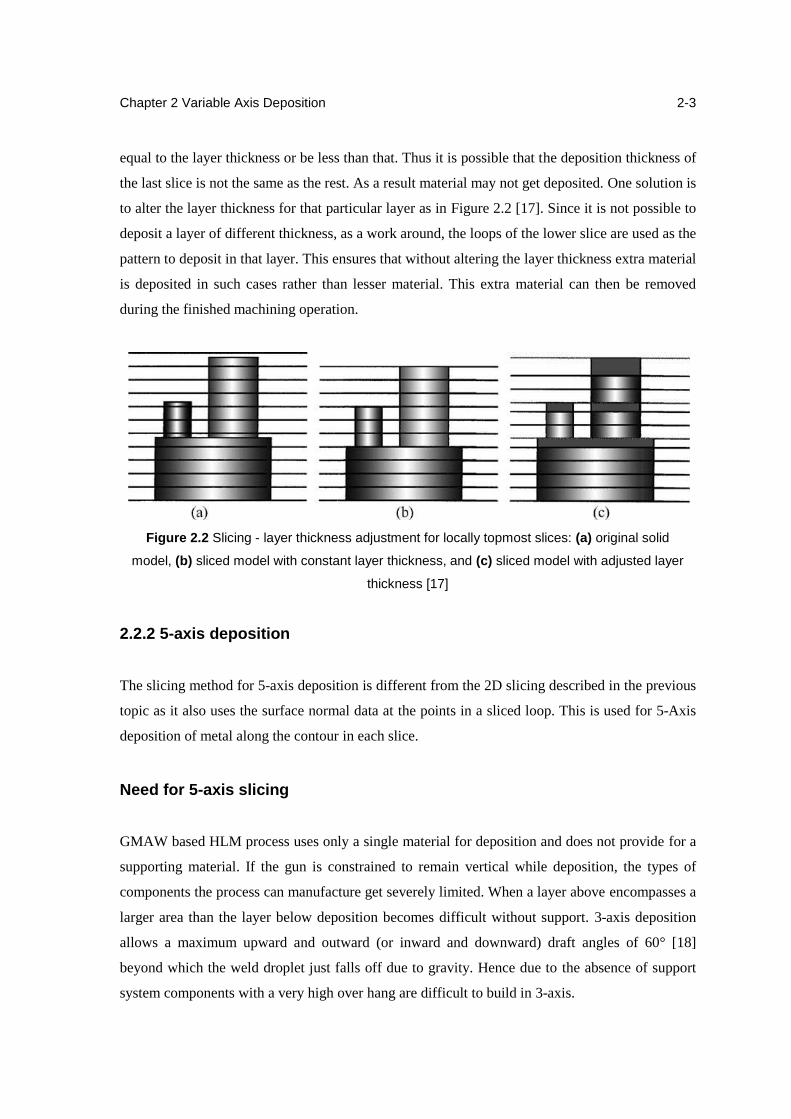
equal to the layer thickness or be less than that. Thus it is possible that the deposition thickness of
the last slice is not the same as the rest. As a result material may not get deposited. One solution is
to alter the layer thickness for that particular layer as in Figure 2.2 [17]. Since it is not possible to
deposit a layer of different thickness, as a work around, the loops of the lower slice are used as the
pattern to deposit in that layer. This ensures that without altering the layer thickness extra material
is deposited in such cases rather than lesser material. This extra material can then be removed
during the finished machining operation.
Figure 2.2 Slicing - layer thickness adjustment for locally topmost slices: (a) original solid
model, (b) sliced model with constant layer thickness, and (c) sliced model with adjusted layer
thickness [17]
2.2.2 5-axis deposition
The slicing method for 5-axis deposition is different from the 2D slicing described in the previous
topic as it also uses the surface normal data at the points in a sliced loop. This is used for 5-Axis
deposition of metal along the contour in each slice.
Need for 5-axis slicing
GMAW based HLM process uses only a single material for deposition and does not provide for a
supporting material. If the gun is constrained to remain vertical while deposition, the types of
components the process can manufacture get severely limited. When a layer above encompasses a
larger area than the layer below deposition becomes difficult without support. 3-axis deposition
allows a maximum upward and outward (or inward and downward) draft angles of 60° [18]
beyond which the weld droplet just falls off due to gravity. Hence due to the absence of support
system components with a very high over hang are difficult to build in 3-axis.
Chapter 2 Variable Axis Deposition
2-4
The solution to this problem is 5-axis deposition of the boundary contours. In 5-axis HLM at
IIT Bombay, the welding gun relative to the work plane has continuously variable five degrees of
freedom along the X, Y, Z, A and C axes. When depositing along the contours in a slice, the
welding nozzle aligns itself such that it points along the torch vector. The deposition becomes
undercut-free. This ensures that when a droplet of metal from the nozzle falls under gravity it is
incident at the right spot on the component being built. In short the table is titled to capture the
falling droplet. This not only increases the manufacturing capability of HLM to a variety of
objects but also produces a more accurate near-net shape as compared to the 3-axis deposition.
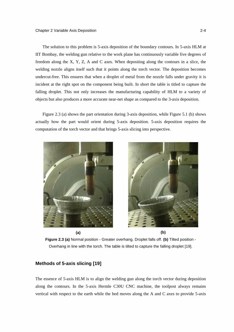
Figure 2.3 (a) shows the part orientation during 3-axis deposition, while Figure 5.1 (b) shows
actually how the part would orient during 5-axis deposition. 5-axis deposition requires the
computation of the torch vector and that brings 5-axis slicing into perspective.
(a)
(b)
Figure 2.3 (a) Normal position - Greater overhang. Droplet falls off. (b) Tilted position -
Overhang in line with the torch. The table is tilted to capture the falling droplet [19].
Methods of 5-axis slicing [19]
The essence of 5-axis HLM is to align the welding gun along the torch vector during deposition
along the contours. In the 5-axis Hermle C30U CNC machine, the toolpost always remains
vertical with respect to the earth while the bed moves along the A and C axes to provide 5-axis
Chapter 2 Variable Axis Deposition
2-5
control. During depositing the weld droplet falls vertically downwards due to gravity. The build
object is tilted such that the normal to the model surface becomes horizontal and thus orthogonal
to the welding gun. Here two methods for 5-axis slices are discussed as below.
(a) Cross product method
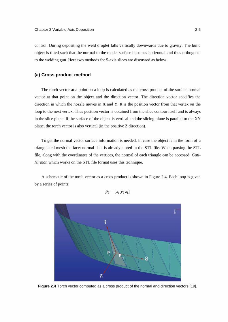
The torch vector at a point on a loop is calculated as the cross product of the surface normal
vector at that point on the object and the direction vector. The direction vector specifies the
direction in which the nozzle moves in X and Y. It is the position vector from that vertex on the
loop to the next vertex. Thus position vector is obtained from the slice contour itself and is always
in the slice plane. If the surface of the object is vertical and the slicing plane is parallel to the XY
plane, the torch vector is also vertical (in the positive Z direction).
To get the normal vector surface information is needed. In case the object is in the form of a
triangulated mesh the facet normal data is already stored in the STL file. When parsing the STL
file, along with the coordinates of the vertices, the normal of each triangle can be accessed. Gati-
Nirman which works on the STL file format uses this technique.
A schematic of the torch vector as a cross product is shown in Figure 2.4. Each loop is given
by a series of points:
�̅�𝑖 = [𝑥𝑖 𝑦𝑖 𝑧𝑖]
Figure 2.4 Torch vector computed as a cross product of the normal and direction vectors [19].
Chapter 2 Variable Axis Deposition
2-6
where z remains constant for a slice. Each of these points is additionally associated with a
torch vector:
�̂�𝑖 = [𝑖𝑖 𝑗𝑖 𝑘𝑖]
It is calculated as follows:
�̂�𝑖 = �̂�𝑖 × p̅i+1 − p̅𝑖
‖p̅i+1 − p̅𝑖‖
(b) Double Slice Method
In some cases, the normal data to a point may not be easily accessible. For example, in
DelCAM, when slicing an object consisting of free-form surfaces, the normal at the slice points
can be found from the surface on which the point lies. This surface has to be identified first. If the
object contains a large number of such surfaces (a common occurrence in complex geometries)
then the task becomes tedious. Instead of calculating the torch vector via the cross product route,
one looks for other options to estimate the same. Intuitively the torch vector shows the direction
and the degree to which the model surface is inclined to the X-Y plane.
In the double slice method another slice is created at a small offset (example 0.1 mm) above
the slicing plane. For every ith contour on the lower slice say 𝐶𝑖0 there should exist a
corresponding contour on the slice above 𝐶𝑖1. If this condition is not satisfied, then a reduced or a
negative offset value is chosen. The two curves 𝐶𝑖0 and 𝐶𝑖
1 are then repointed together so that they
are discretized into equal number of segments. They define a ruled surface between them. The
longitudes of the ruled surface give the direction of the torch vector. Another analogy that can be
drawn is that of a wireframe swarf. The tool axis or the gun is constrained to lie along the
longitudes.
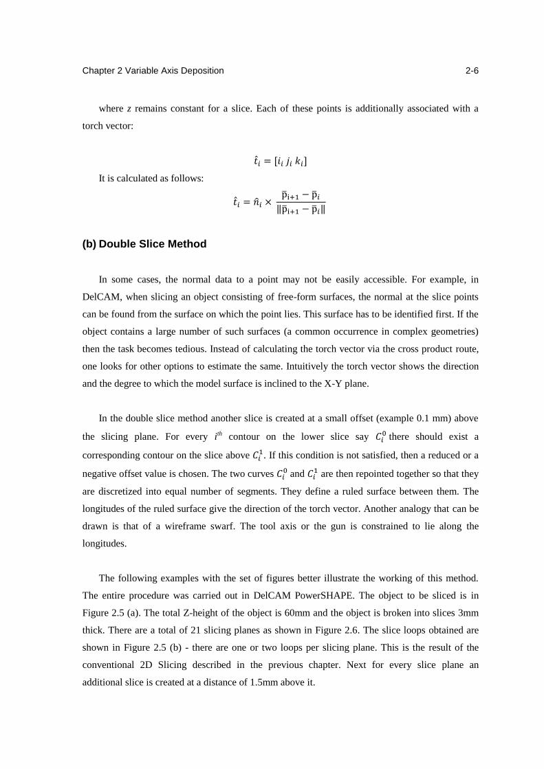
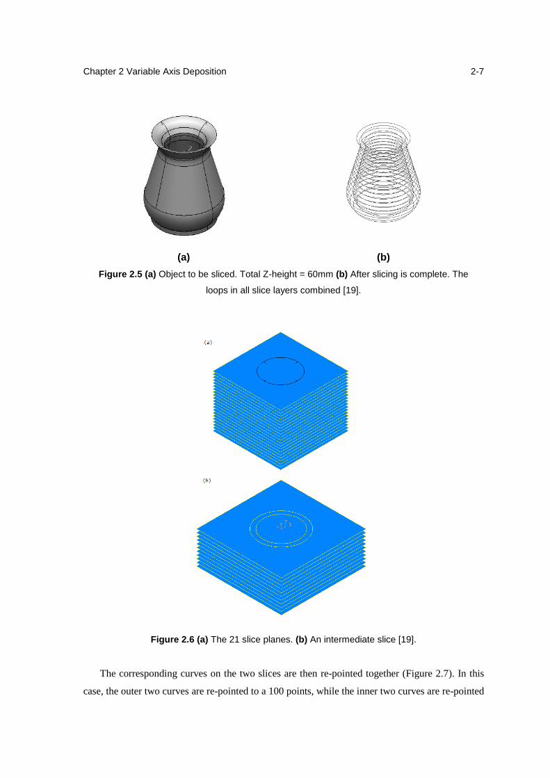
The following examples with the set of figures better illustrate the working of this method.
The entire procedure was carried out in DelCAM PowerSHAPE. The object to be sliced is in
Figure 2.5 (a). The total Z-height of the object is 60mm and the object is broken into slices 3mm
thick. There are a total of 21 slicing planes as shown in Figure 2.6. The slice loops obtained are
shown in Figure 2.5 (b) - there are one or two loops per slicing plane. This is the result of the
conventional 2D Slicing described in the previous chapter. Next for every slice plane an
additional slice is created at a distance of 1.5mm above it.
Chapter 2 Variable Axis Deposition
2-7
(a) (b)
Figure 2.5 (a) Object to be sliced. Total Z-height = 60mm (b) After slicing is complete. The
loops in all slice layers combined [19].
Figure 2.6 (a) The 21 slice planes. (b) An intermediate slice [19].
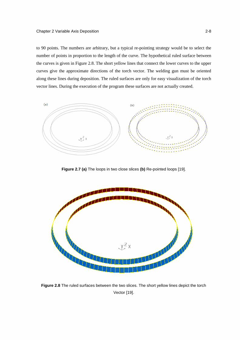
The corresponding curves on the two slices are then re-pointed together (Figure 2.7). In this
case, the outer two curves are re-pointed to a 100 points, while the inner two curves are re-pointed
Chapter 2 Variable Axis Deposition
2-8
to 90 points. The numbers are arbitrary, but a typical re-pointing strategy would be to select the
number of points in proportion to the length of the curve. The hypothetical ruled surface between
the curves is given in Figure 2.8. The short yellow lines that connect the lower curves to the upper
curves give the approximate directions of the torch vector. The welding gun must be oriented
along these lines during deposition. The ruled surfaces are only for easy visualization of the torch
vector lines. During the execution of the program these surfaces are not actually created.
Figure 2.7 (a) The loops in two close slices (b) Re-pointed loops [19].
Figure 2.8 The ruled surfaces between the two slices. The short yellow lines depict the torch
Vector [19].
Chapter 2 Variable Axis Deposition
2-9
2.3 Feature Based Deposition
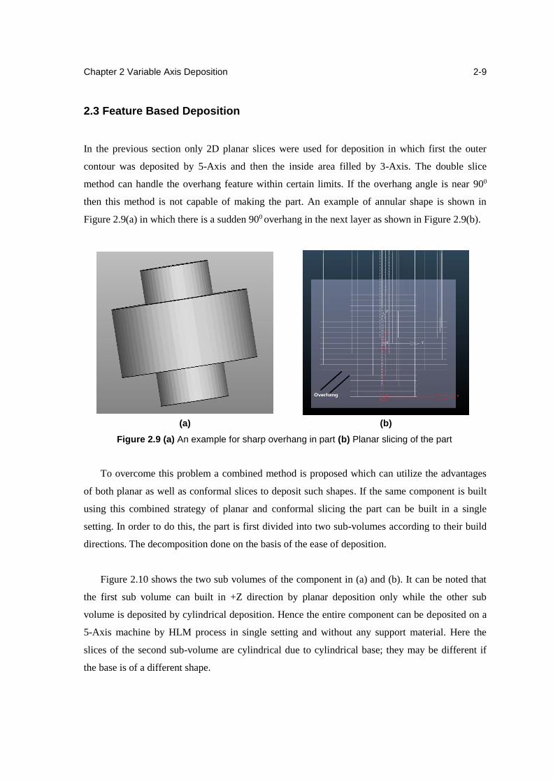
In the previous section only 2D planar slices were used for deposition in which first the outer
contour was deposited by 5-Axis and then the inside area filled by 3-Axis. The double slice
method can handle the overhang feature within certain limits. If the overhang angle is near 900
then this method is not capable of making the part. An example of annular shape is shown in
Figure 2.9(a) in which there is a sudden 900 overhang in the next layer as shown in Figure 2.9(b).
(a) (b)
Figure 2.9 (a) An example for sharp overhang in part (b) Planar slicing of the part
To overcome this problem a combined method is proposed which can utilize the advantages
of both planar as well as conformal slices to deposit such shapes. If the same component is built
using this combined strategy of planar and conformal slicing the part can be built in a single
setting. In order to do this, the part is first divided into two sub-volumes according to their build
directions. The decomposition done on the basis of the ease of deposition.
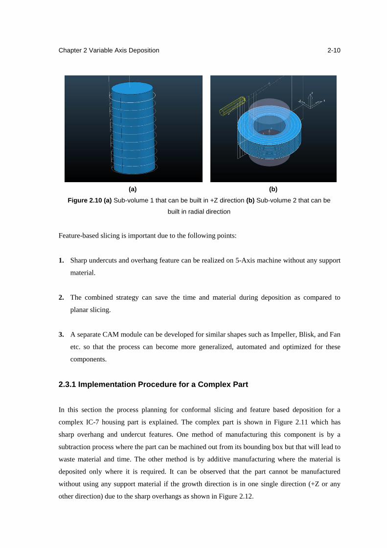
Figure 2.10 shows the two sub volumes of the component in (a) and (b). It can be noted that
the first sub volume can built in +Z direction by planar deposition only while the other sub
volume is deposited by cylindrical deposition. Hence the entire component can be deposited on a
5-Axis machine by HLM process in single setting and without any support material. Here the
slices of the second sub-volume are cylindrical due to cylindrical base; they may be different if
the base is of a different shape.
Chapter 2 Variable Axis Deposition
2-10
(a) (b)
Figure 2.10 (a) Sub-volume 1 that can be built in +Z direction (b) Sub-volume 2 that can be
built in radial direction
Feature-based slicing is important due to the following points:
1. Sharp undercuts and overhang feature can be realized on 5-Axis machine without any support
material.
2. The combined strategy can save the time and material during deposition as compared to
planar slicing.
3. A separate CAM module can be developed for similar shapes such as Impeller, Blisk, and Fan
etc. so that the process can become more generalized, automated and optimized for these
components.
2.3.1 Implementation Procedure for a Complex Part
In this section the process planning for conformal slicing and feature based deposition for a
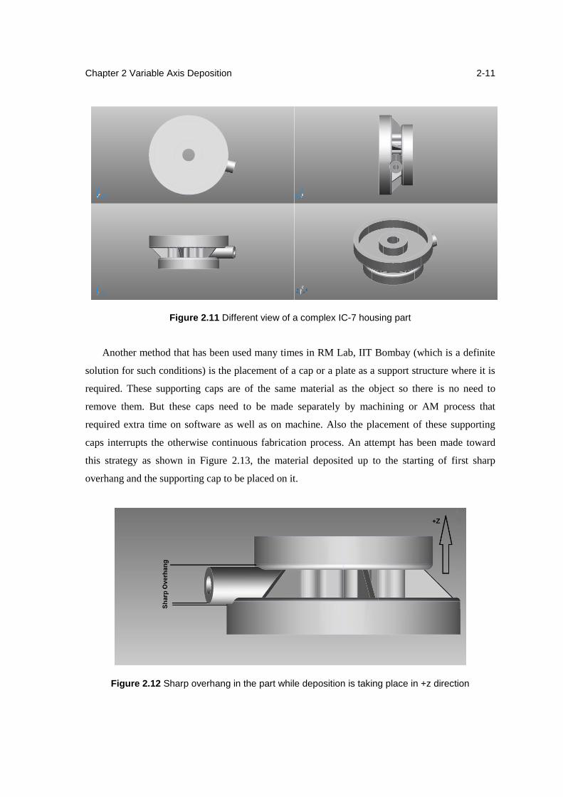
complex IC-7 housing part is explained. The complex part is shown in Figure 2.11 which has
sharp overhang and undercut features. One method of manufacturing this component is by a
subtraction process where the part can be machined out from its bounding box but that will lead to
waste material and time. The other method is by additive manufacturing where the material is
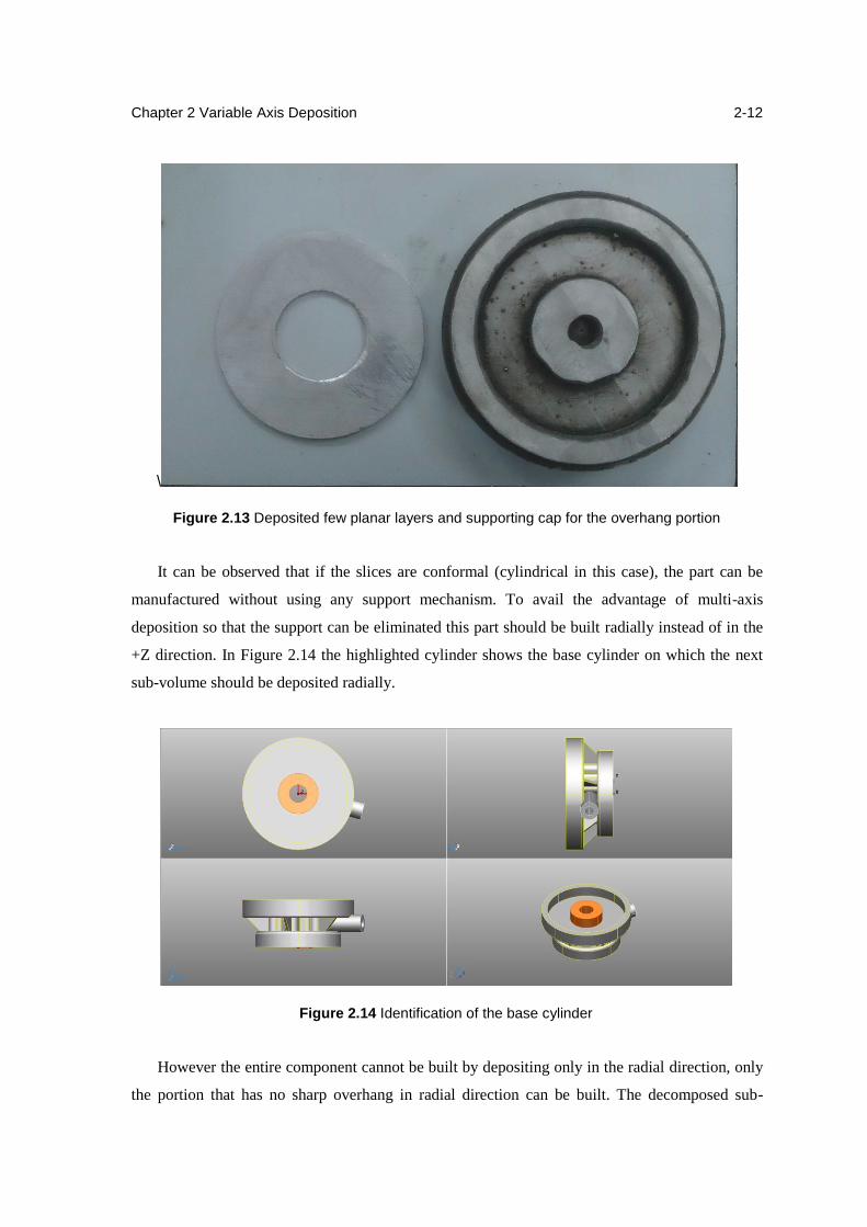
deposited only where it is required. It can be observed that the part cannot be manufactured
without using any support material if the growth direction is in one single direction (+Z or any
other direction) due to the sharp overhangs as shown in Figure 2.12.
Chapter 2 Variable Axis Deposition
2-11
Figure 2.11 Different view of a complex IC-7 housing part
Another method that has been used many times in RM Lab, IIT Bombay (which is a definite
solution for such conditions) is the placement of a cap or a plate as a support structure where it is
required. These supporting caps are of the same material as the object so there is no need to
remove them. But these caps need to be made separately by machining or AM process that
required extra time on software as well as on machine. Also the placement of these supporting
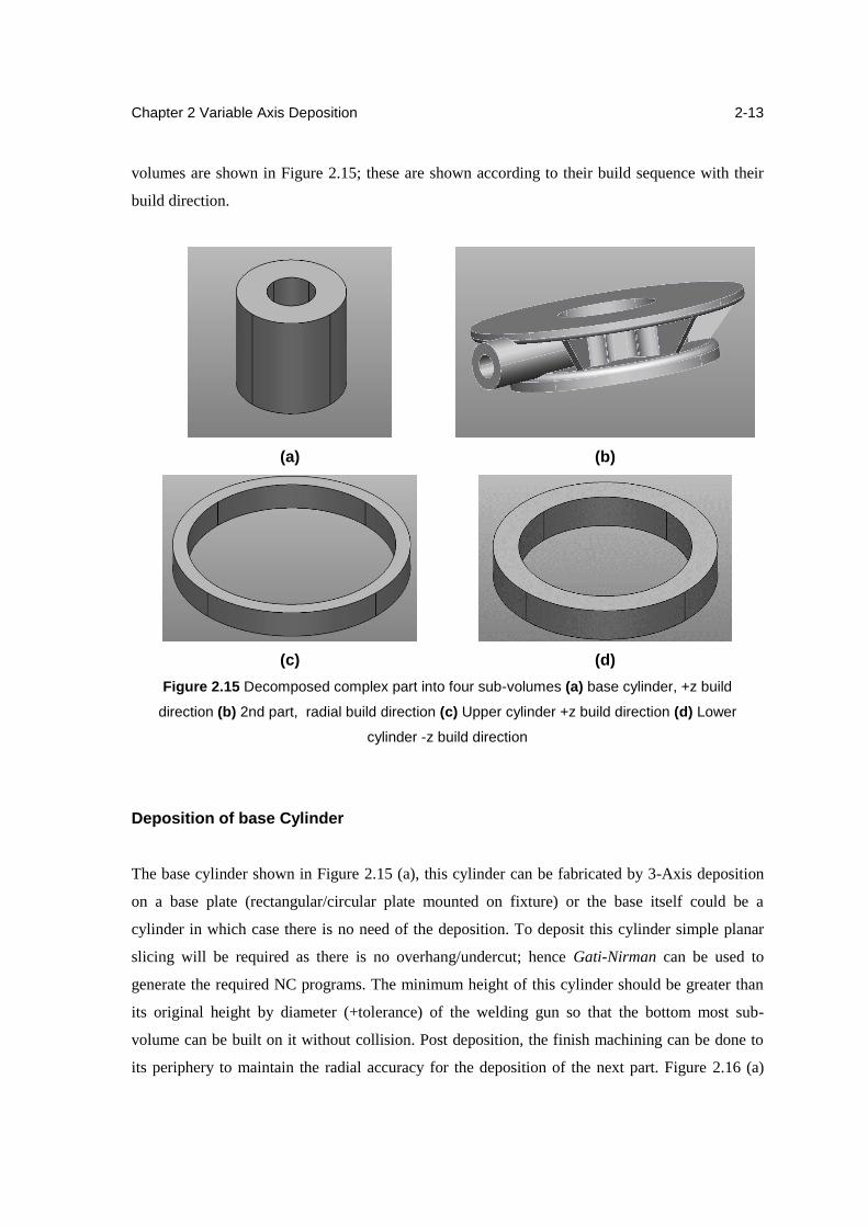
caps interrupts the otherwise continuous fabrication process. An attempt has been made toward
this strategy as shown in Figure 2.13, the material deposited up to the starting of first sharp
overhang and the supporting cap to be placed on it.
Figure 2.12 Sharp overhang in the part while deposition is taking place in +z direction
Chapter 2 Variable Axis Deposition
2-12
\
Figure 2.13 Deposited few planar layers and supporting cap for the overhang portion
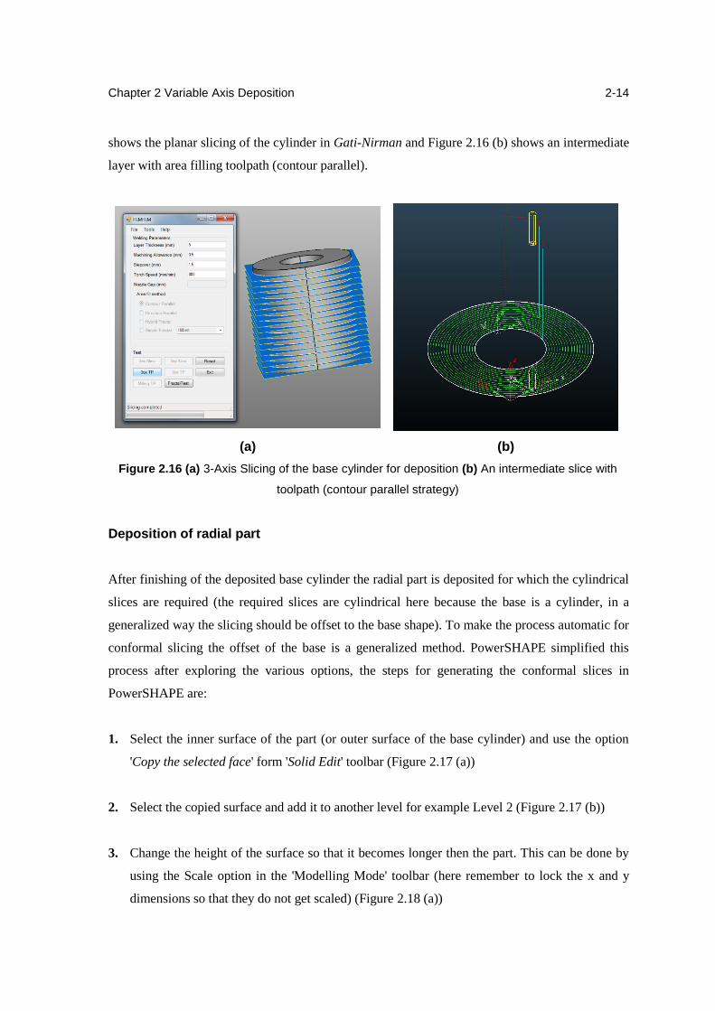
It can be observed that if the slices are conformal (cylindrical in this case), the part can be
manufactured without using any support mechanism. To avail the advantage of multi-axis
deposition so that the support can be eliminated this part should be built radially instead of in the
+Z direction. In Figure 2.14 the highlighted cylinder shows the base cylinder on which the next
sub-volume should be deposited radially.
Figure 2.14 Identification of the base cylinder
However the entire component cannot be built by depositing only in the radial direction, only
the portion that has no sharp overhang in radial direction can be built. The decomposed sub-
Chapter 2 Variable Axis Deposition
2-13
volumes are shown in Figure 2.15; these are shown according to their build sequence with their
build direction.
(a) (b)
(c) (d)
Figure 2.15 Decomposed complex part into four sub-volumes (a) base cylinder, +z build
direction (b) 2nd part, radial build direction (c) Upper cylinder +z build direction (d) Lower
cylinder -z build direction
Deposition of base Cylinder
The base cylinder shown in Figure 2.15 (a), this cylinder can be fabricated by 3-Axis deposition
on a base plate (rectangular/circular plate mounted on fixture) or the base itself could be a
cylinder in which case there is no need of the deposition. To deposit this cylinder simple planar
slicing will be required as there is no overhang/undercut; hence Gati-Nirman can be used to
generate the required NC programs. The minimum height of this cylinder should be greater than
its original height by diameter (+tolerance) of the welding gun so that the bottom most sub-
volume can be built on it without collision. Post deposition, the finish machining can be done to
its periphery to maintain the radial accuracy for the deposition of the next part. Figure 2.16 (a)
Chapter 2 Variable Axis Deposition
2-14
shows the planar slicing of the cylinder in Gati-Nirman and Figure 2.16 (b) shows an intermediate
layer with area filling toolpath (contour parallel).
(a) (b)
Figure 2.16 (a) 3-Axis Slicing of the base cylinder for deposition (b) An intermediate slice with
toolpath (contour parallel strategy)
Deposition of radial part
After finishing of the deposited base cylinder the radial part is deposited for which the cylindrical
slices are required (the required slices are cylindrical here because the base is a cylinder, in a
generalized way the slicing should be offset to the base shape). To make the process automatic for
conformal slicing the offset of the base is a generalized method. PowerSHAPE simplified this
process after exploring the various options, the steps for generating the conformal slices in
PowerSHAPE are:
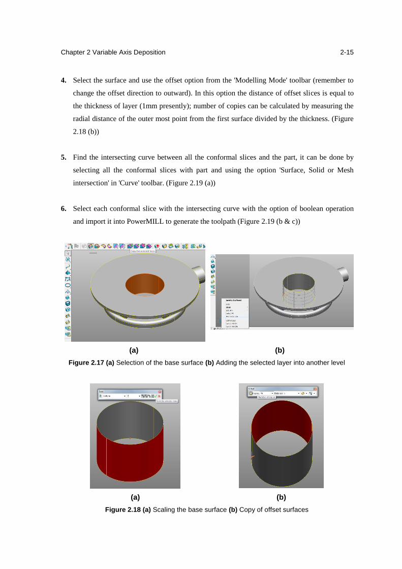
1. Select the inner surface of the part (or outer surface of the base cylinder) and use the option
'Copy the selected face' form 'Solid Edit' toolbar (Figure 2.17 (a))
2. Select the copied surface and add it to another level for example Level 2 (Figure 2.17 (b))
3. Change the height of the surface so that it becomes longer then the part. This can be done by
using the Scale option in the 'Modelling Mode' toolbar (here remember to lock the x and y
dimensions so that they do not get scaled) (Figure 2.18 (a))
Chapter 2 Variable Axis Deposition
2-15
4. Select the surface and use the offset option from the 'Modelling Mode' toolbar (remember to
change the offset direction to outward). In this option the distance of offset slices is equal to
the thickness of layer (1mm presently); number of copies can be calculated by measuring the
radial distance of the outer most point from the first surface divided by the thickness. (Figure
2.18 (b))
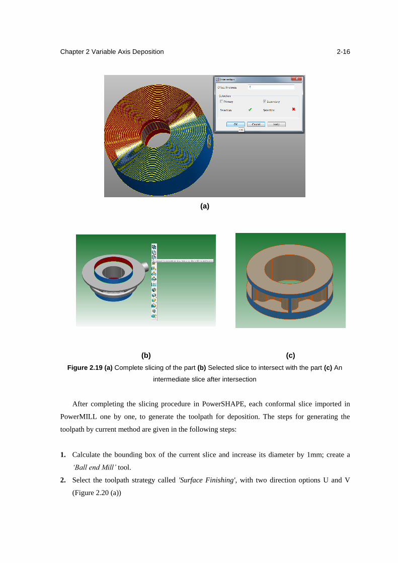
5. Find the intersecting curve between all the conformal slices and the part, it can be done by
selecting all the conformal slices with part and using the option 'Surface, Solid or Mesh
intersection' in 'Curve' toolbar. (Figure 2.19 (a))
6. Select each conformal slice with the intersecting curve with the option of boolean operation
and import it into PowerMILL to generate the toolpath (Figure 2.19 (b & c))
(a) (b)
Figure 2.17 (a) Selection of the base surface (b) Adding the selected layer into another level
(a) (b)
Figure 2.18 (a) Scaling the base surface (b) Copy of offset surfaces
Chapter 2 Variable Axis Deposition
2-16
(a)
(b) (c)
Figure 2.19 (a) Complete slicing of the part (b) Selected slice to intersect with the part (c) An
intermediate slice after intersection
After completing the slicing procedure in PowerSHAPE, each conformal slice imported in
PowerMILL one by one, to generate the toolpath for deposition. The steps for generating the
toolpath by current method are given in the following steps:
1. Calculate the bounding box of the current slice and increase its diameter by 1mm; create a
‘Ball end Mill’ tool.
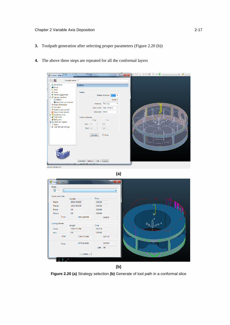
2. Select the toolpath strategy called 'Surface Finishing', with two direction options U and V
(Figure 2.20 (a))
Chapter 2 Variable Axis Deposition
2-17
3. Toolpath generation after selecting proper parameters (Figure 2.20 (b))
4. The above three steps are repeated for all the conformal layers
(a)
(b)
Figure 2.20 (a) Strategy selection (b) Generate of tool path in a conformal slice
Chapter 2 Variable Axis Deposition
2-18
Many toolpath strategies have been explored in PowerMILL after option of pattern but still no
satisfactory method has yet been found. There are two option for toolpath generation, one in U
direction (horizontal direction Figure 2.20 (b)) and another in V direction vertical but there is no
combined strategy is there. In the selected strategy 94 lifts have been took place which is not
acceptable. If we find the combination of two strategy in U and V direction, then optimal toolpath
with less number of lifts can be generate.
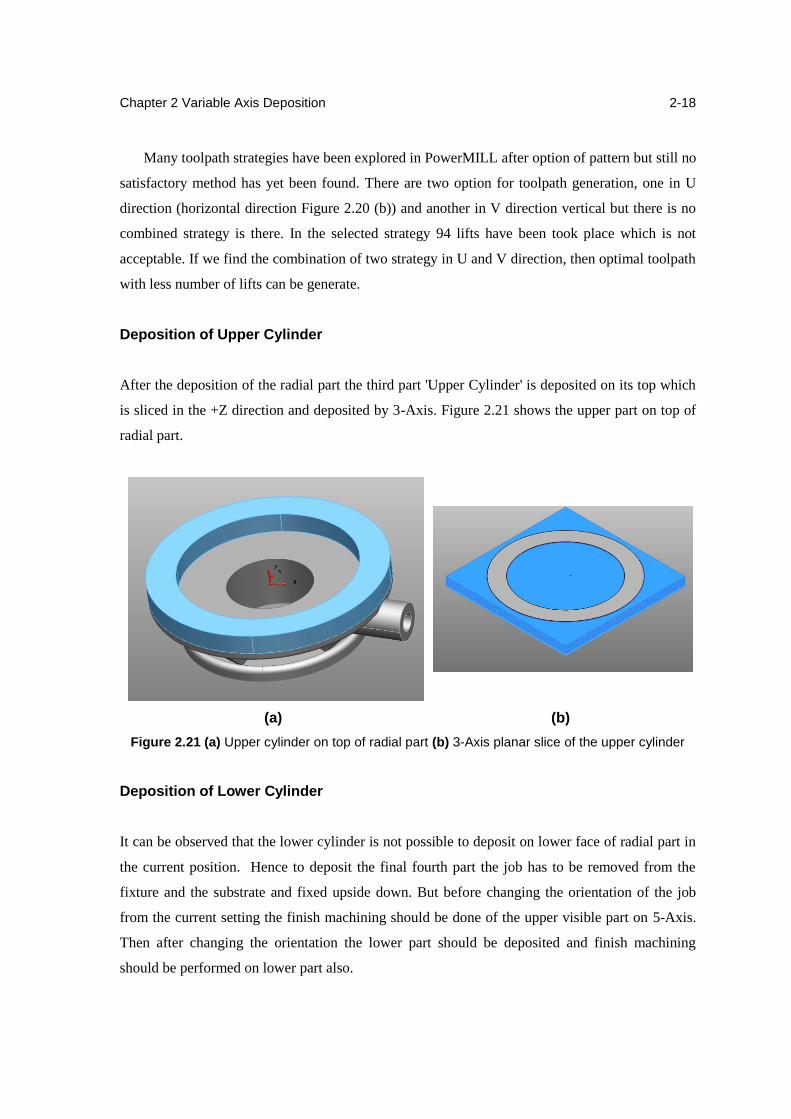
Deposition of Upper Cylinder
After the deposition of the radial part the third part 'Upper Cylinder' is deposited on its top which
is sliced in the +Z direction and deposited by 3-Axis. Figure 2.21 shows the upper part on top of
radial part.
(a) (b)
Figure 2.21 (a) Upper cylinder on top of radial part (b) 3-Axis planar slice of the upper cylinder
Deposition of Lower Cylinder
It can be observed that the lower cylinder is not possible to deposit on lower face of radial part in
the current position. Hence to deposit the final fourth part the job has to be removed from the
fixture and the substrate and fixed upside down. But before changing the orientation of the job
from the current setting the finish machining should be done of the upper visible part on 5-Axis.
Then after changing the orientation the lower part should be deposited and finish machining
should be performed on lower part also.

Chapter 2 Variable Axis Deposition
2-19
2.4 Summary
In this Chapter various planar and non-planar slicing methods were explored, the conformal
slicing or feature based slicing was introduced. The feature based conformal AM can fabricate the
complex geometries without using any support mechanism, the capability was proved by taking
an example of complex IC-7 housing part.
Chapter 3
Integral Substrate Method
3.1 Introduction
Several deposition methods have been studied in the previous chapter. In all of them the deposition
has been started from some base metal plate which has been removed by face milling after
deposition. It has been seen that if we use integral substrate which become part of the deposited
component then it increases strength of the part as the forged/rolled substrate is reinforced and it
can be worked as skeleton for the component. The same clamping setup can be used for machining
as well as deposition so, the final component can be produce without changing the clamping
arrangement. Also the substrate can be use with best engagement in the component, so the
efficiency can be increase by using less material. In this chapter a new integral substrate method
has been explain by an example of turbine blade.
3.2 Methodology
In HLM process the basic steps are as import the CAD model in CAM package, slicing of the CAD
model in Gati-Nirman, generate tool path for each layer and deposit each layer. Here in integral
substrate method few steps have been changed which discussed in detail as below.
3.2.1 Maximum consumable volume of substrate
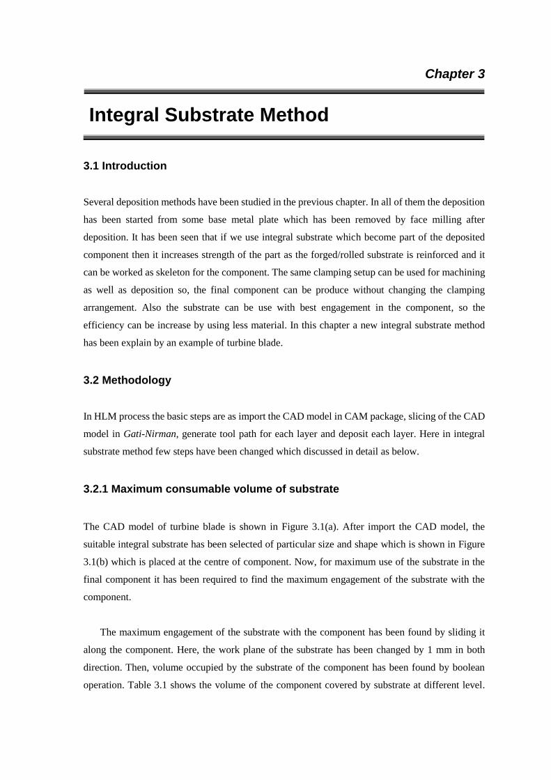
The CAD model of turbine blade is shown in Figure 3.1(a). After import the CAD model, the
suitable integral substrate has been selected of particular size and shape which is shown in Figure
3.1(b) which is placed at the centre of component. Now, for maximum use of the substrate in the
final component it has been required to find the maximum engagement of the substrate with the
component.
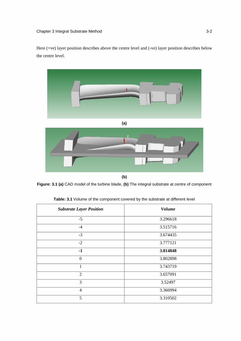
The maximum engagement of the substrate with the component has been found by sliding it
along the component. Here, the work plane of the substrate has been changed by 1 mm in both
direction. Then, volume occupied by the substrate of the component has been found by boolean
operation. Table 3.1 shows the volume of the component covered by substrate at different level.
Chapter 3 Integral Substrate Method
3-2
Here (+ve) layer position describes above the centre level and (-ve) layer position describes below
the centre level.
(a)
(b)
Figure: 3.1 (a) CAD model of the turbine blade, (b) The integral substrate at centre of component
Table: 3.1 Volume of the component covered by the substrate at different level
Substrate Layer Position Volume
-5 3.296618
-4 3.515716
-3 3.674435
-2 3.777121
-1 3.814848
0 3.802898
1 3.743719
2 3.657091
3 3.52497
4 3.366994
5 3.310502
Chapter 3 Integral Substrate Method
3-3
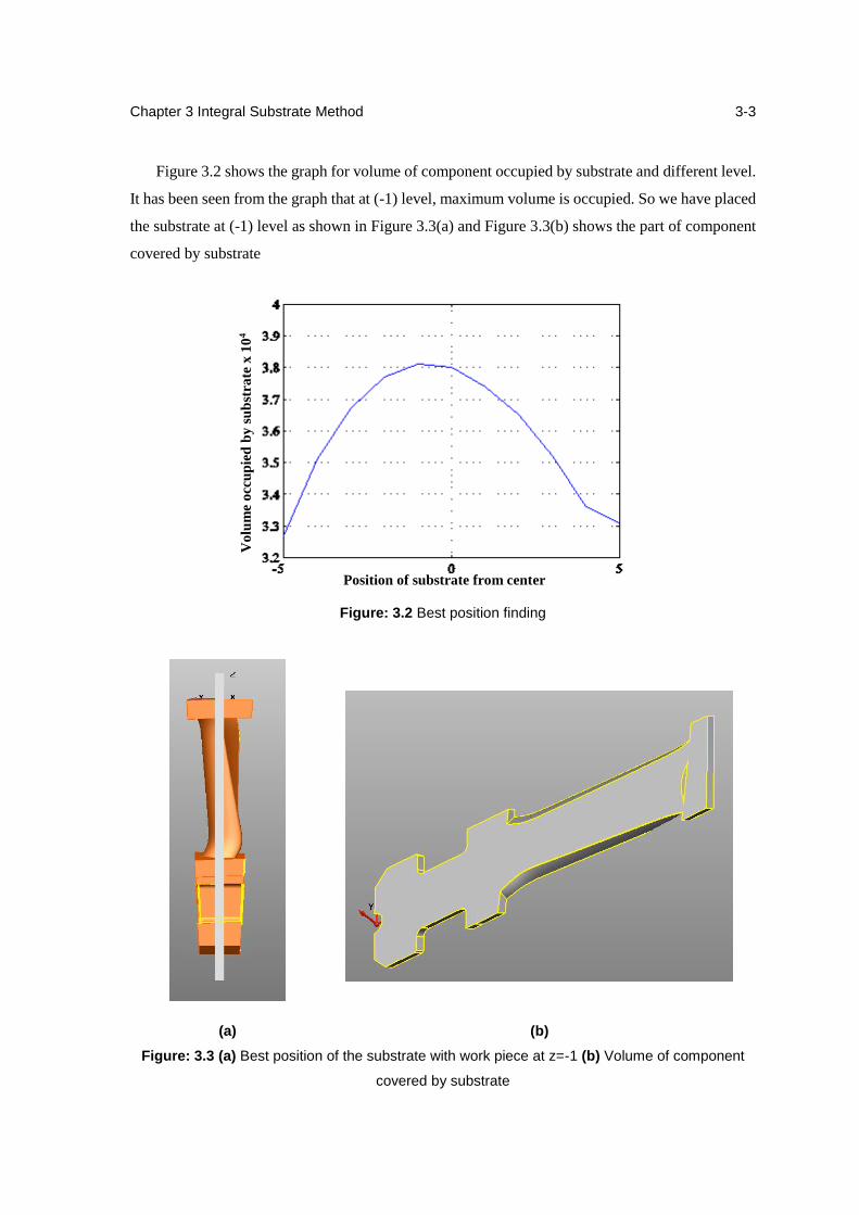
Figure 3.2 shows the graph for volume of component occupied by substrate and different level.
It has been seen from the graph that at (-1) level, maximum volume is occupied. So we have placed
the substrate at (-1) level as shown in Figure 3.3(a) and Figure 3.3(b) shows the part of component
covered by substrate
Figure: 3.2 Best position finding
(a) (b)
Figure: 3.3 (a) Best position of the substrate with work piece at z=-1 (b) Volume of component
covered by substrate
Position of substrate from center
Vo
lum
e o
ccu
pie
d b
y s
ub
stra
te x
10
4
Chapter 3 Integral Substrate Method
3-4
3.2.2 Slicing and near net CAD model
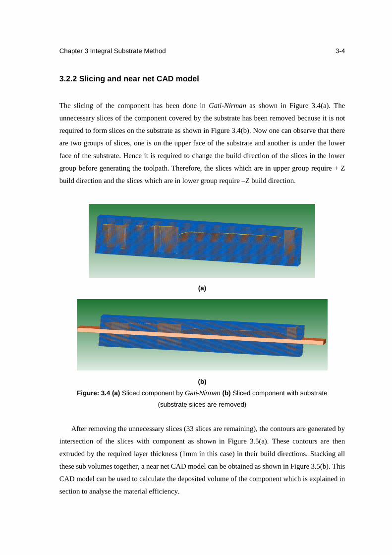
The slicing of the component has been done in Gati-Nirman as shown in Figure 3.4(a). The
unnecessary slices of the component covered by the substrate has been removed because it is not
required to form slices on the substrate as shown in Figure 3.4(b). Now one can observe that there
are two groups of slices, one is on the upper face of the substrate and another is under the lower
face of the substrate. Hence it is required to change the build direction of the slices in the lower
group before generating the toolpath. Therefore, the slices which are in upper group require + Z
build direction and the slices which are in lower group require –Z build direction.
(a)
(b)
Figure: 3.4 (a) Sliced component by Gati-Nirman (b) Sliced component with substrate
(substrate slices are removed)
After removing the unnecessary slices (33 slices are remaining), the contours are generated by
intersection of the slices with component as shown in Figure 3.5(a). These contours are then
extruded by the required layer thickness (1mm in this case) in their build directions. Stacking all
these sub volumes together, a near net CAD model can be obtained as shown in Figure 3.5(b). This
CAD model can be used to calculate the deposited volume of the component which is explained in
section to analyse the material efficiency.
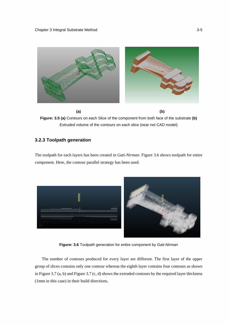
Chapter 3 Integral Substrate Method
3-5
(a) (b)
Figure: 3.5 (a) Contours on each Slice of the component from both face of the substrate (b)
Extruded volume of the contours on each slice (near net CAD model)
3.2.3 Toolpath generation
The toolpath for each layers has been created in Gati-Nirman. Figure 3.6 shows toolpath for entire
component. Here, the contour parallel strategy has been used.
Figure: 3.6 Toolpath generation for entire component by Gati-Nirman
The number of contours produced for every layer are different. The first layer of the upper
group of slices contains only one contour whereas the eighth layer contains four contours as shown
in Figure 3.7 (a, b) and Figure 3.7 (c, d) shows the extruded contours by the required layer thickness
(1mm in this case) in their build directions.
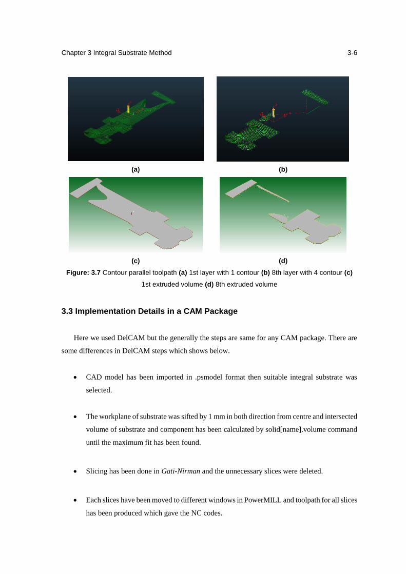
Chapter 3 Integral Substrate Method
3-6
(a) (b)
(c) (d)
Figure: 3.7 Contour parallel toolpath (a) 1st layer with 1 contour (b) 8th layer with 4 contour (c)
1st extruded volume (d) 8th extruded volume
3.3 Implementation Details in a CAM Package
Here we used DelCAM but the generally the steps are same for any CAM package. There are
some differences in DelCAM steps which shows below.
CAD model has been imported in .psmodel format then suitable integral substrate was
selected.
The workplane of substrate was sifted by 1 mm in both direction from centre and intersected
volume of substrate and component has been calculated by solid[name].volume command
until the maximum fit has been found.
Slicing has been done in Gati-Nirman and the unnecessary slices were deleted.
Each slices have been moved to different windows in PowerMILL and toolpath for all slices
has been produced which gave the NC codes.
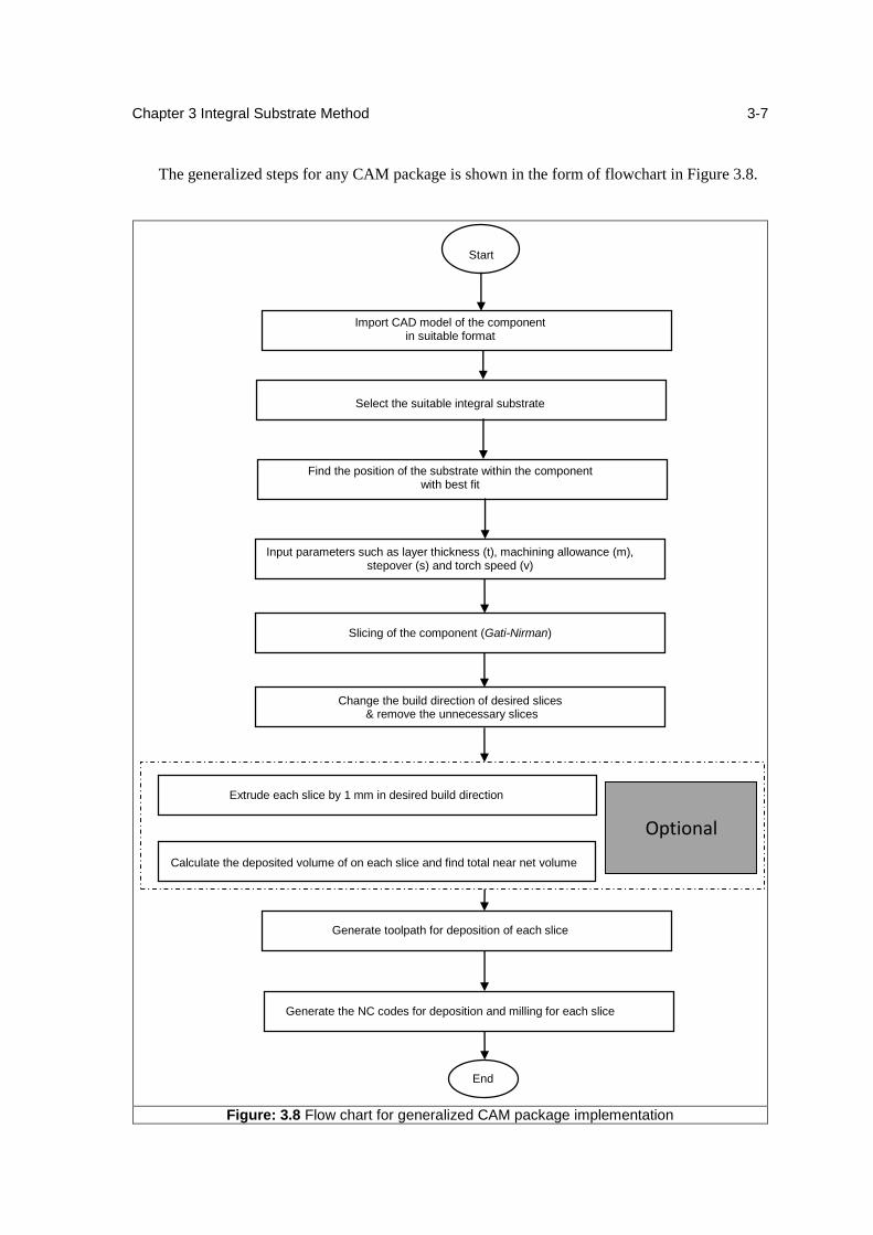
Chapter 3 Integral Substrate Method
3-7
The generalized steps for any CAM package is shown in the form of flowchart in Figure 3.8.
Start
Import CAD model of the component in suitable format
Select the suitable integral substrate
Find the position of the substrate within the component with best fit
Input parameters such as layer thickness (t), machining allowance (m), stepover (s) and torch speed (v)
Slicing of the component (Gati-Nirman)
Change the build direction of desired slices & remove the unnecessary slices
Extrude each slice by 1 mm in desired build direction
Calculate the deposited volume of on each slice and find total near net volume
Generate toolpath for deposition of each slice
Generate the NC codes for deposition and milling for each slice
End
Figure: 3.8 Flow chart for generalized CAM package implementation
Optional
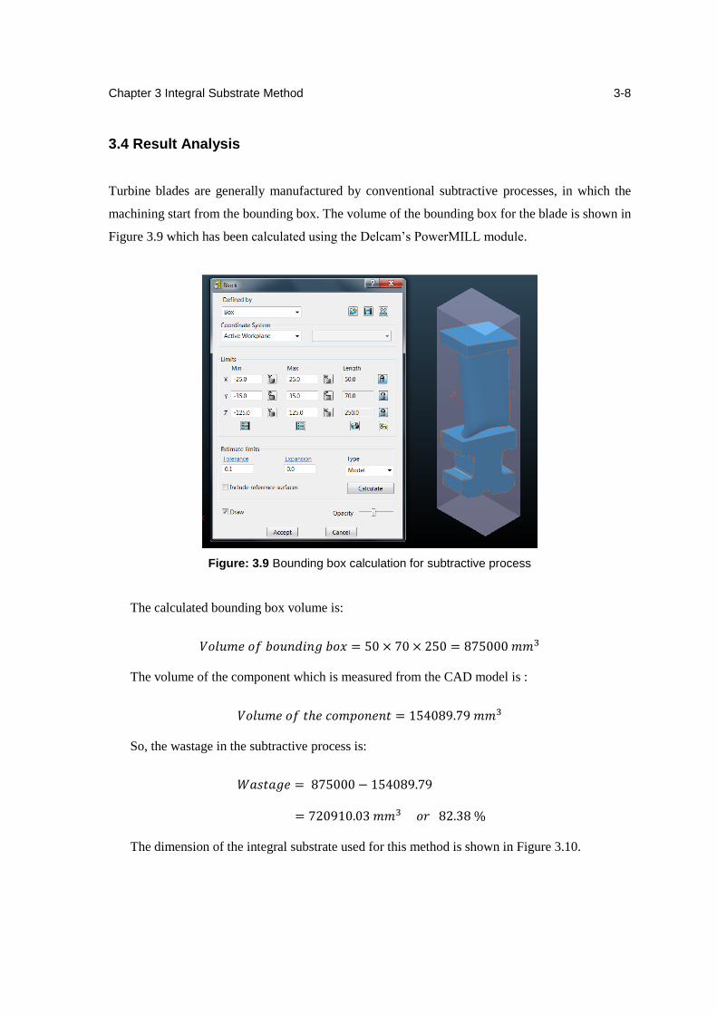
Chapter 3 Integral Substrate Method
3-8
3.4 Result Analysis
Turbine blades are generally manufactured by conventional subtractive processes, in which the
machining start from the bounding box. The volume of the bounding box for the blade is shown in
Figure 3.9 which has been calculated using the Delcam’s PowerMILL module.
Figure: 3.9 Bounding box calculation for subtractive process
The calculated bounding box volume is:
𝑉𝑜𝑙𝑢𝑚𝑒 𝑜𝑓 𝑏𝑜𝑢𝑛𝑑𝑖𝑛𝑔 𝑏𝑜𝑥 = 50 × 70 × 250 = 875000 𝑚𝑚3
The volume of the component which is measured from the CAD model is :
𝑉𝑜𝑙𝑢𝑚𝑒 𝑜𝑓 𝑡ℎ𝑒 𝑐𝑜𝑚𝑝𝑜𝑛𝑒𝑛𝑡 = 154089.79 𝑚𝑚3
So, the wastage in the subtractive process is:
𝑊𝑎𝑠𝑡𝑎𝑔𝑒 = 875000 − 154089.79
= 720910.03 𝑚𝑚3 𝑜𝑟 82.38 %
The dimension of the integral substrate used for this method is shown in Figure 3.10.
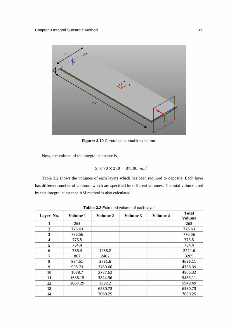
Chapter 3 Integral Substrate Method
3-9
Figure: 3.10 Central consumable substrate
Now, the volume of the integral substrate is,
= 5 × 70 × 250 = 87500 𝑚𝑚3
Table 3.2 shows the volumes of each layers which has been required to deposite. Each layer
has different number of contours which are specified by different volumes. The total volume used
by this integral substance AM method is also calculated.
Table: 3.2 Extruded volume of each layer
Layer No. Volume 1 Volume 2 Volume 3 Volume 4 Total
Volume
1 263 263
2 776.63 776.63
3 776.56 776.56
4 776.5 776.5
5 764.4 764.4
6 786.4 1438.2 2224.6
7 807 2462 3269
8 864.51 3761.6 4626.11
9 998.73 3769.66 4768.39
10 1078.7 3787.62 4866.32
11 1638.15 3824.96 5463.11
12 2067.29 3882.2 5949.49
13 6580.73 6580.73
14 7060.25 7060.25
70
250
5
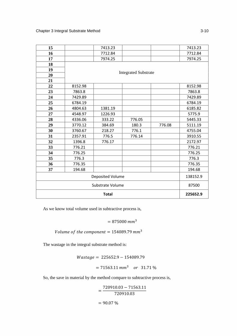
Chapter 3 Integral Substrate Method
3-10
15 7413.23 7413.23
16 7712.84 7712.84
17 7974.25 7974.25
18
Integrated Substrate 19
20
21
22 8152.98 8152.98
23 7863.8 7863.8
24 7429.89 7429.89
25 6784.19 6784.19
26 4804.63 1381.19 6185.82
27 4548.97 1226.93 5775.9
28 4336.06 333.22 776.05 5445.33
29 3770.12 384.69 180.3 776.08 5111.19
30 3760.67 218.27 776.1 4755.04
31 2357.91 776.5 776.14 3910.55
32 1396.8 776.17 2172.97
33 776.21 776.21
34 776.25 776.25
35 776.3 776.3
36 776.35 776.35
37 194.68 194.68
Deposited Volume 138152.9
Substrate Volume 87500
Total 225652.9
As we know total volume used in subtractive process is,
= 875000 𝑚𝑚3
𝑉𝑜𝑙𝑢𝑚𝑒 𝑜𝑓 𝑡ℎ𝑒 𝑐𝑜𝑚𝑝𝑜𝑛𝑒𝑛𝑡 = 154089.79 𝑚𝑚3
The wastage in the integral substrate method is:
𝑊𝑎𝑠𝑡𝑎𝑔𝑒 = 225652.9 − 154089.79
= 71563.11 𝑚𝑚3 𝑜𝑟 31.71 %
So, the save in material by the method compare to subtractive process is,
=720910.03 − 71563.11
720910.03
= 90.07 %
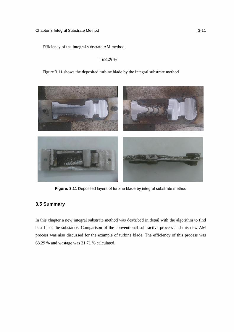
Chapter 3 Integral Substrate Method
3-11
Efficiency of the integral substrate AM method,
= 68.29 %
Figure 3.11 shows the deposited turbine blade by the integral substrate method.
Figure: 3.11 Deposited layers of turbine blade by integral substrate method
3.5 Summary
In this chapter a new integral substrate method was described in detail with the algorithm to find
best fit of the substance. Comparison of the conventional subtractive process and this new AM
process was also discussed for the example of turbine blade. The efficiency of this process was
68.29 % and wastage was 31.71 % calculated.
Chapter 4
An Integrated Multi-Station HLM
4.1 Introduction
This chapter describes the requirement to develop an integrated multi-station multi-axis Hybrid
Layered Manufacturing facility for producing exotic metallic components through an optimal
combination of MIG and TIG (PAW) deposition. Which can be help to build simple monolithic
objects out of Fe, Al, Ni and Ti alloys, characterize them and fine-tune the process from the
results and to validate the process for complex monolithic aero-engine components out of Fe, Al,
Ni and Ti alloys. In the end of the chapter one conceptual design is also suggested.
4.2 Need for Integrated Multi-Station HLM
Hybrid Layered Manufacturing (HLM) is a direct Additive Manufacturing (AM) process
developed in IIT Bombay about a decade ago. The commercial viability of HLM has been
established for tooling applications including composite tools (MS core and P20/H13 tool steel
case) with Conformal Cooling Channels (CCC). HLM was extended 2 years ago with 5-axis
deposition to realize more complex parts such as an Al impeller. 5-axis kinematics is used for
eliminating the need for support structures. While currently HLM uses MIG weld deposition, it is
being extended for using TIG (PAW), each of the two finding their specific applications differing
in speed, precision and cost. The ultimate aim of HLM is to produce aerospace components that
are typical of complex geometries and exotic materials. While 5-axis kinematics enables HLM
realize complex geometries, tool steels and exotic materials require preheating of the substrate
and stress relieving through cold working. So, HLM can no longer be a simple retrofitment of a 5-
axis CNC machine and the deposition head. Instead, an integrated multi-station multi-axis HLM
facility will be required to produce complex metallic aero-engine components with the required
interior and surface quality economically and quickly. While the primary goal of this phase will
be on monolithic components, preliminary work will be done for gradient objects.
Until we were dealing with soft and simple materials like MS and Al, there was no need for
preheating or stress relieving. Therefore, only weld deposition and face milling were required
which could be done on the same CNC machine. However, tool steels and exotic materials require
preheating and/or stress relieving. It is also felt important to inspect each layer automatically
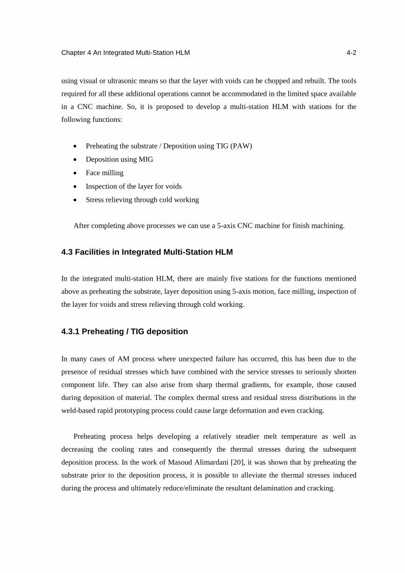
Chapter 4 An Integrated Multi-Station HLM
4-2
using visual or ultrasonic means so that the layer with voids can be chopped and rebuilt. The tools
required for all these additional operations cannot be accommodated in the limited space available
in a CNC machine. So, it is proposed to develop a multi-station HLM with stations for the
following functions:
Preheating the substrate / Deposition using TIG (PAW)
Deposition using MIG
Face milling
Inspection of the layer for voids
Stress relieving through cold working
After completing above processes we can use a 5-axis CNC machine for finish machining.
4.3 Facilities in Integrated Multi-Station HLM
In the integrated multi-station HLM, there are mainly five stations for the functions mentioned
above as preheating the substrate, layer deposition using 5-axis motion, face milling, inspection of
the layer for voids and stress relieving through cold working.
4.3.1 Preheating / TIG deposition
In many cases of AM process where unexpected failure has occurred, this has been due to the
presence of residual stresses which have combined with the service stresses to seriously shorten
component life. They can also arise from sharp thermal gradients, for example, those caused
during deposition of material. The complex thermal stress and residual stress distributions in the
weld-based rapid prototyping process could cause large deformation and even cracking.
Preheating process helps developing a relatively steadier melt temperature as well as
decreasing the cooling rates and consequently the thermal stresses during the subsequent
deposition process. In the work of Masoud Alimardani [20], it was shown that by preheating the
substrate prior to the deposition process, it is possible to alleviate the thermal stresses induced
during the process and ultimately reduce/eliminate the resultant delamination and cracking.
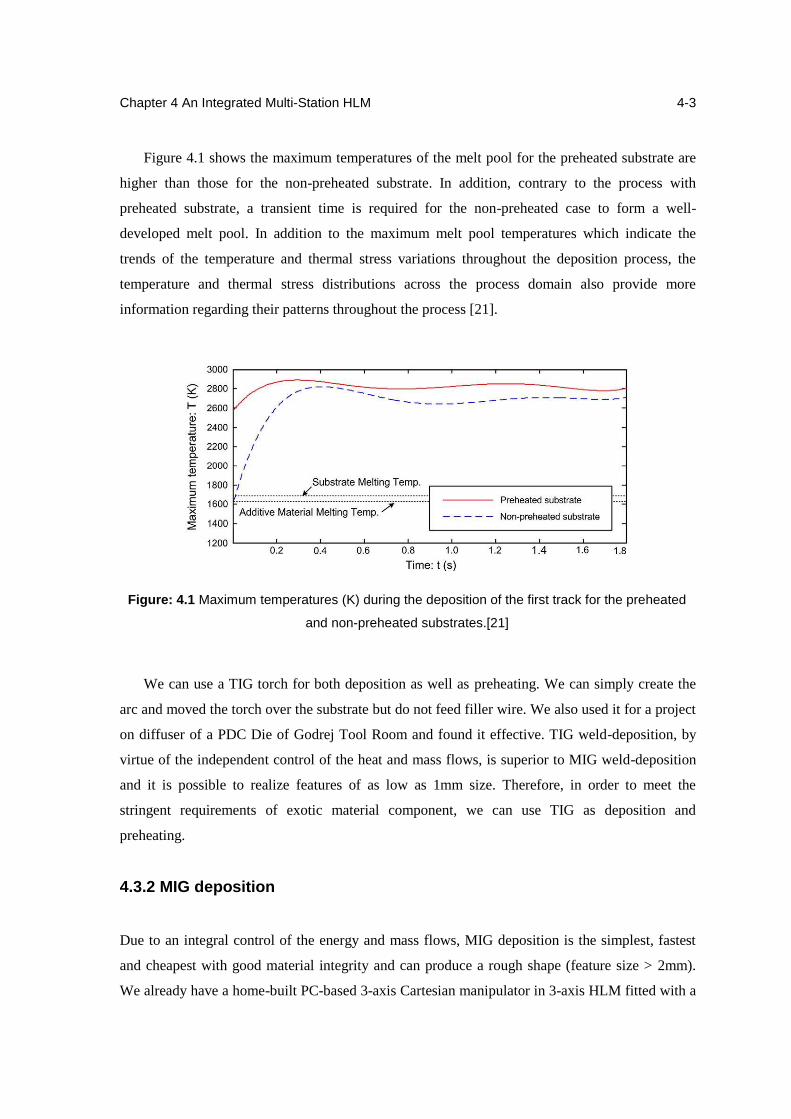
Chapter 4 An Integrated Multi-Station HLM
4-3
Figure 4.1 shows the maximum temperatures of the melt pool for the preheated substrate are
higher than those for the non-preheated substrate. In addition, contrary to the process with
preheated substrate, a transient time is required for the non-preheated case to form a well-
developed melt pool. In addition to the maximum melt pool temperatures which indicate the
trends of the temperature and thermal stress variations throughout the deposition process, the
temperature and thermal stress distributions across the process domain also provide more
information regarding their patterns throughout the process [21].
Figure: 4.1 Maximum temperatures (K) during the deposition of the first track for the preheated
and non-preheated substrates.[21]
We can use a TIG torch for both deposition as well as preheating. We can simply create the
arc and moved the torch over the substrate but do not feed filler wire. We also used it for a project
on diffuser of a PDC Die of Godrej Tool Room and found it effective. TIG weld-deposition, by
virtue of the independent control of the heat and mass flows, is superior to MIG weld-deposition
and it is possible to realize features of as low as 1mm size. Therefore, in order to meet the
stringent requirements of exotic material component, we can use TIG as deposition and
preheating.
4.3.2 MIG deposition
Due to an integral control of the energy and mass flows, MIG deposition is the simplest, fastest
and cheapest with good material integrity and can produce a rough shape (feature size > 2mm).
We already have a home-built PC-based 3-axis Cartesian manipulator in 3-axis HLM fitted with a
Chapter 4 An Integrated Multi-Station HLM
4-4
Fronius MIG weld-deposition system which has been extended 2 years ago with 5-axis deposition
to realize more complex parts such as an Al impeller. We have achieved 130 g/min in MIG-
deposition and it can reach as much as 1,000 g/min with proper heat management. So we can
directly use it for the multi-station HLM.
4.3.3 Face milling
As we know HLM is a combination of additive and subtractive manufacturing. In HLM after
deposition of every single layer, face milling has been done to remove the scallops and scale and
to ensure the desired layer thickness. In planar deposition, simple face milling is adequate to
achieve this. In non-planar deposition, conformal milling using a ball end mill will be required.
This station will mainly contain a tool head which can use for face milling after deposition with a
CNC controller.
4.3.4 Inspection
After deposition and face milling, it has been observed that defects as porosity, unfilled area took
place which has been reduced the capabilies of the parts. Figure 4.2 shows some defected parts
which did not inspect during deposition.
(a)
(b)
Figure: 4.2 Defected parts (a) Porosity defect, (b) Unfilled area
This station will contain an inspection using optical systems and image processing or
ultrasonic or inductive sensors by which we can check the surface after each layer. If the layer is
found to have any voids or any other defects, it can be removed and re-deposited.
Chapter 4 An Integrated Multi-Station HLM
4-5
4.3.5 Cold working
Due to the enormous heat generated during the welding process, the workpiece develops high
amount of residual thermal stresses. Residual stresses often have a negative effect on the
mechanical properties of a workpiece leading to service failure. Thus, they can adversely affect
the life of the component manufactured by Hybrid Layered Manufacturing (HLM) process. Also
they are frequently the cause for the occurrence of undesirable dimensional changes in the
workpiece upon machining. Therefore HLM is modified to minimize residual stresses by
permitting them to be relieved or distributed on a wide area. This modification was done by
integrating a pneumatic hammer to 3-axis CNC machine
Residual stresses caused during welding are a major source of crack propagation. Contraction
of metal along the length of the weld is partially prevented by the large adjacent body of cold
metal. Hence, residual tensile stresses are set up along the weld [22].
Shot peening is a cold working process in which the surface of a part is bombarded with small
spherical shots. Each piece of shot striking the material acts as a tiny peening hammer, imparting
to the surface a small indentation or dimple. It is well known that cracks will not initiate or
propagate in a compressively stressed zone. The maximum compressive residual stress produced
at or under the surface of a part helps in increasing resistance to fatigue failures, corrosion fatigue,
stress by corrosion cracking, hydrogen assisted cracking, fretting, galling and erosion caused by
cavitation [23].
The peening of layers by the CNC integrated pneumatic hammer is a hot working process. It
is used to produce a compressive residual stress layer and to modify mechanical properties of
HLM components. Plastic deformation induces a residual compressive stress in a hammered
surface, along with tensile stress in the interior. Surface compressive stresses confer resistance to
metal fatigue and to some forms of stress corrosion. The tensile stresses deep in the part are not as
problematic as tensile stresses on the surface because cracks are less likely to initiate in the
interior.
Figure 4.3 shows the hammer setup which currently used in 3-axis CNC. We can use this type
of setup for the integrated multi-station HLM as well.
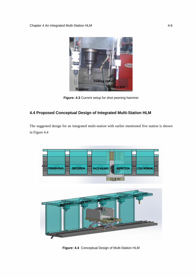
Chapter 4 An Integrated Multi-Station HLM
4-6
Figure: 4.3 Current setup for shot peening hammer
4.4 Proposed Conceptual Design of Integrated Multi-Station HLM
The suggested design for an integrated multi-station with earlier mentioned five station is shown
in Figure 4.4
Figure: 4.4 Conceptual Design of Multi-Station HLM
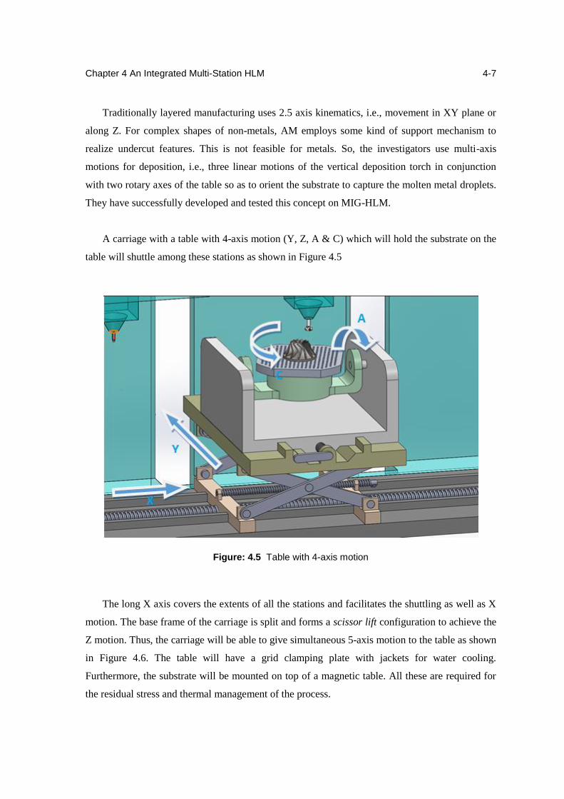
Chapter 4 An Integrated Multi-Station HLM
4-7
Traditionally layered manufacturing uses 2.5 axis kinematics, i.e., movement in XY plane or
along Z. For complex shapes of non-metals, AM employs some kind of support mechanism to
realize undercut features. This is not feasible for metals. So, the investigators use multi-axis
motions for deposition, i.e., three linear motions of the vertical deposition torch in conjunction
with two rotary axes of the table so as to orient the substrate to capture the molten metal droplets.
They have successfully developed and tested this concept on MIG-HLM.
A carriage with a table with 4-axis motion (Y, Z, A & C) which will hold the substrate on the
table will shuttle among these stations as shown in Figure 4.5
Figure: 4.5 Table with 4-axis motion
The long X axis covers the extents of all the stations and facilitates the shuttling as well as X
motion. The base frame of the carriage is split and forms a scissor lift configuration to achieve the
Z motion. Thus, the carriage will be able to give simultaneous 5-axis motion to the table as shown
in Figure 4.6. The table will have a grid clamping plate with jackets for water cooling.
Furthermore, the substrate will be mounted on top of a magnetic table. All these are required for
the residual stress and thermal management of the process.
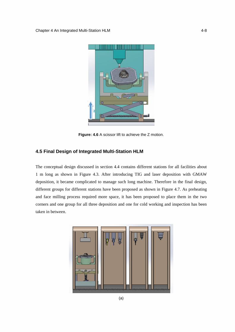
Chapter 4 An Integrated Multi-Station HLM
4-8
Figure: 4.6 A scissor lift to achieve the Z motion.
4.5 Final Design of Integrated Multi-Station HLM
The conceptual design discussed in section 4.4 contains different stations for all facilities about
1 m long as shown in Figure 4.3. After introducing TIG and laser deposition with GMAW
deposition, it became complicated to manage such long machine. Therefore in the final design,
different groups for different stations have been proposed as shown in Figure 4.7. As preheating
and face milling process required more space, it has been proposed to place them in the two
corners and one group for all three deposition and one for cold working and inspection has been
taken in between.
(a)
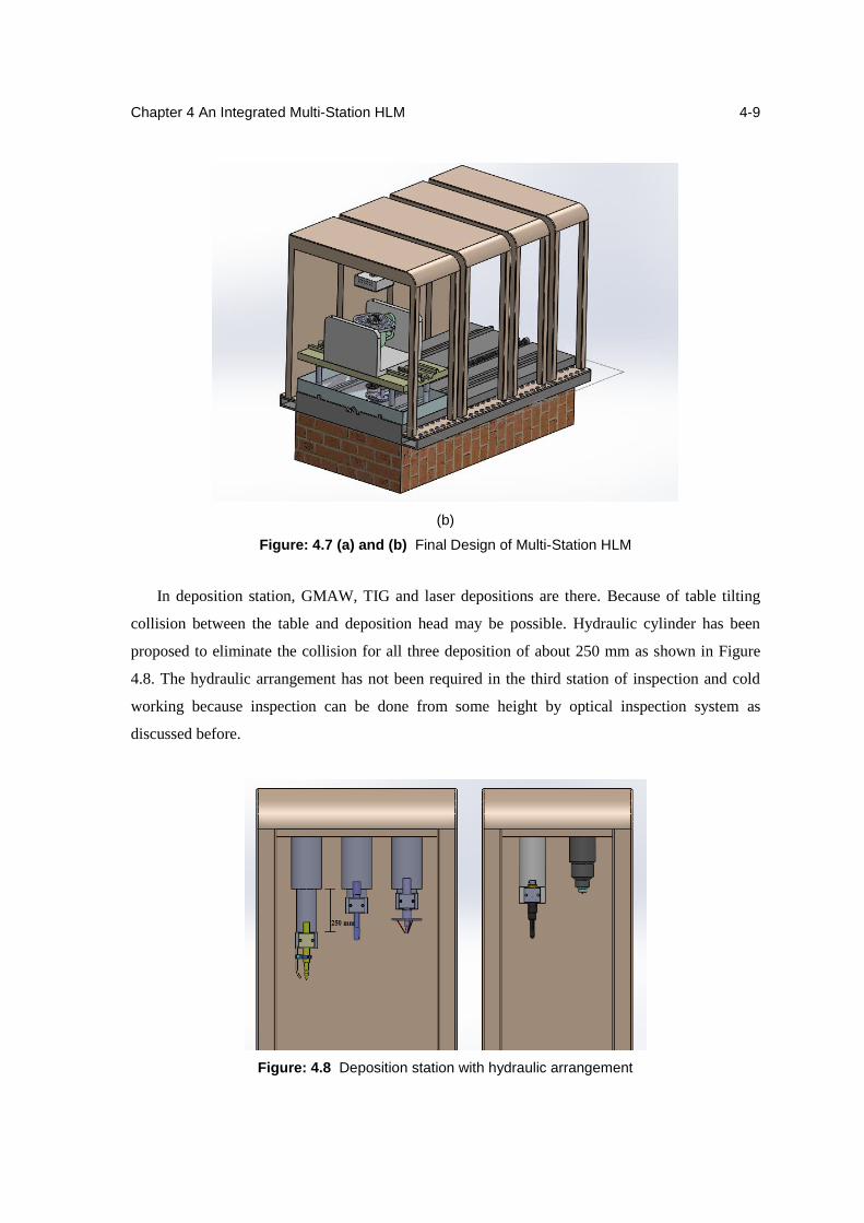
Chapter 4 An Integrated Multi-Station HLM
4-9
(b)
Figure: 4.7 (a) and (b) Final Design of Multi-Station HLM
In deposition station, GMAW, TIG and laser depositions are there. Because of table tilting
collision between the table and deposition head may be possible. Hydraulic cylinder has been
proposed to eliminate the collision for all three deposition of about 250 mm as shown in Figure
4.8. The hydraulic arrangement has not been required in the third station of inspection and cold
working because inspection can be done from some height by optical inspection system as
discussed before.
Figure: 4.8 Deposition station with hydraulic arrangement
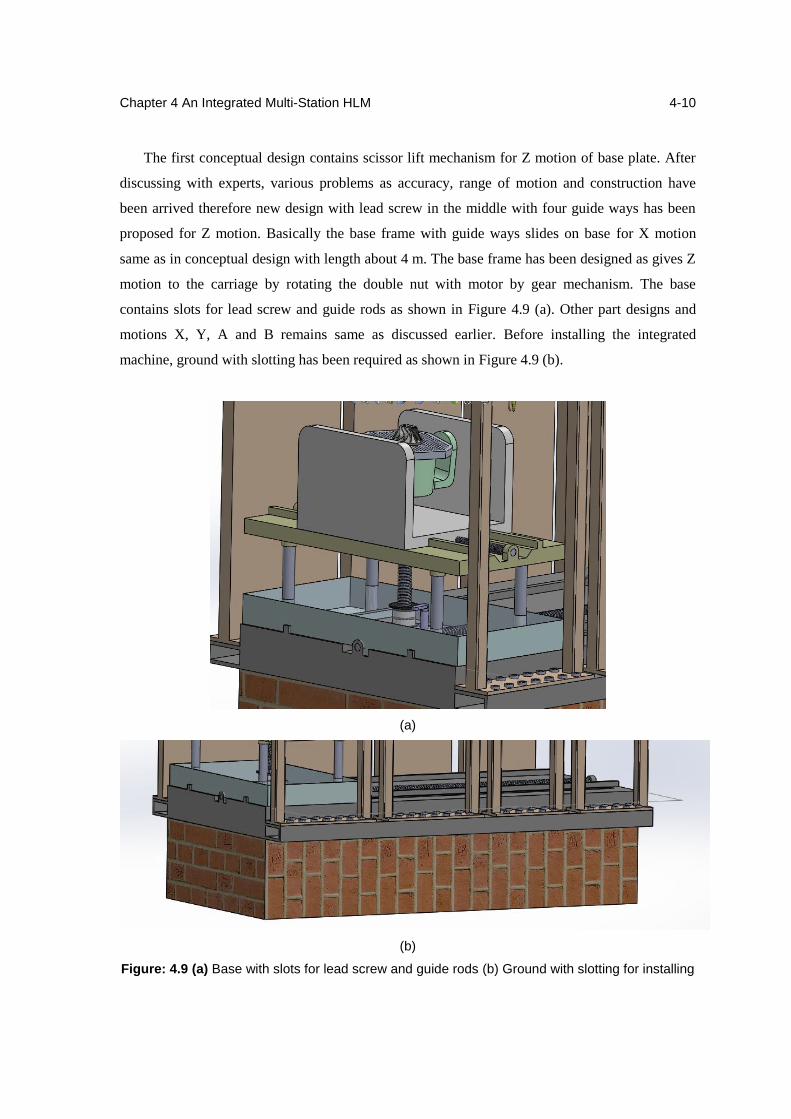
Chapter 4 An Integrated Multi-Station HLM
4-10
The first conceptual design contains scissor lift mechanism for Z motion of base plate. After
discussing with experts, various problems as accuracy, range of motion and construction have
been arrived therefore new design with lead screw in the middle with four guide ways has been
proposed for Z motion. Basically the base frame with guide ways slides on base for X motion
same as in conceptual design with length about 4 m. The base frame has been designed as gives Z
motion to the carriage by rotating the double nut with motor by gear mechanism. The base
contains slots for lead screw and guide rods as shown in Figure 4.9 (a). Other part designs and
motions X, Y, A and B remains same as discussed earlier. Before installing the integrated
machine, ground with slotting has been required as shown in Figure 4.9 (b).
(a)
(b)
Figure: 4.9 (a) Base with slots for lead screw and guide rods (b) Ground with slotting for installing
Chapter 4 An Integrated Multi-Station HLM
4-11
4.5.1 Advantages of lead screw mechanism over scissor lift
More Accurate
Long predictable life
Compact design
Easy construction
Stability
More working range
4.6 Summary
In this chapter the requirement of an integrated multi-station HLM was discussed. We can
produce complex parts from exotic materials or any materials as tool steel which are difficult
without preheating and stress relieving without changing the setup again and again. One
conceptual design and final detailed design for the same has been suggested with multi-axis
configuration.
Chapter 5
In-situ CNC Integrated Pneumatic Hammer
5.1 Introduction
Detrimental residual stresses commonly result from different heating and cooling during HLM
process. Due to contraction of metal along the length of the deposition is partially prevented by the
large adjacent body of cold metal. Hence residual tensile stresses are set up along the deposition.
The residual stresses that arrive during deposition can reach the yield strength of part. Therefore,
some mechanical treatments are required to reduce the residual stresses. This chapter describes the
effect of in-situ CNC integrated pneumatic hammer in HLM process and its working.
5.2 Need of Pneumatic Hammer in HLM
Fatigue is basically a surface related phenomenon as the fatigue cracks initiate at the surface and
grow from there into the material. Surface hardening is therefore often used to improve fatigue
properties and an important example of this is hammering. The in-situ pressing of layers work
hardens the surface layer and induces compressive residual stresses. The residual stress acts as an
applied mean stress and a compressive residual stress will therefore retard fatigue crack initiation
and growth [24]. The work hardening results in an increased dislocation density which hinders
dislocation movements due to the fatigue load and suppresses localized plastic deformation which
is a starting feature for crack initiation. Residual stress in components deposited by HLM is
produced by localized metal tensions occurring immediately after deposition, which are:
a. Contraction stress – This is the main source of residual stress. It takes place during
cooling of the deposited areas, which have undergone non uniform heating.
b. Stress due to higher surface cooling – When the deposited component layer cools
down the surface cools faster than the inside, even if the cooling occurs in still air. The
greater the thickness, the more stress is generated.
c. Stress due to phase transformation – It occurs due to transformation of austenite to
ferrite that causes an increase in volume to which the base metal is opposed [25].
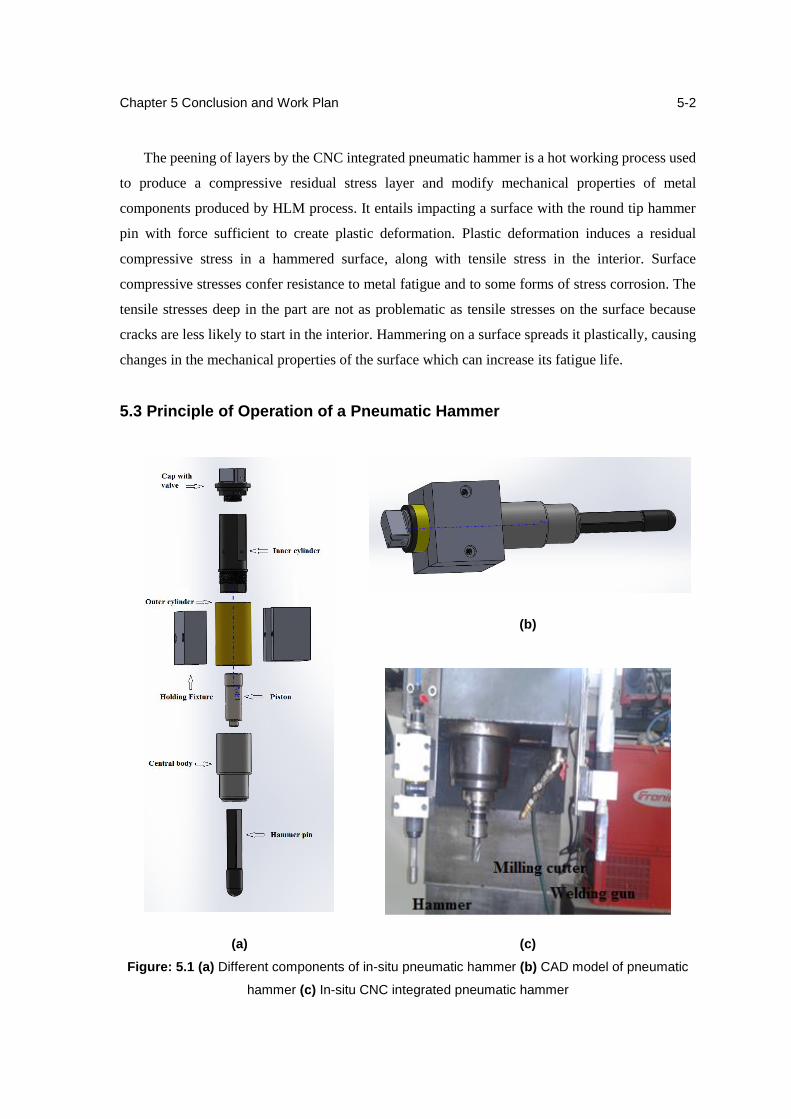
Chapter 5 Conclusion and Work Plan
5-2
The peening of layers by the CNC integrated pneumatic hammer is a hot working process used
to produce a compressive residual stress layer and modify mechanical properties of metal
components produced by HLM process. It entails impacting a surface with the round tip hammer
pin with force sufficient to create plastic deformation. Plastic deformation induces a residual
compressive stress in a hammered surface, along with tensile stress in the interior. Surface
compressive stresses confer resistance to metal fatigue and to some forms of stress corrosion. The
tensile stresses deep in the part are not as problematic as tensile stresses on the surface because
cracks are less likely to start in the interior. Hammering on a surface spreads it plastically, causing
changes in the mechanical properties of the surface which can increase its fatigue life.
5.3 Principle of Operation of a Pneumatic Hammer
(b)
(a) (c)
Figure: 5.1 (a) Different components of in-situ pneumatic hammer (b) CAD model of pneumatic
hammer (c) In-situ CNC integrated pneumatic hammer
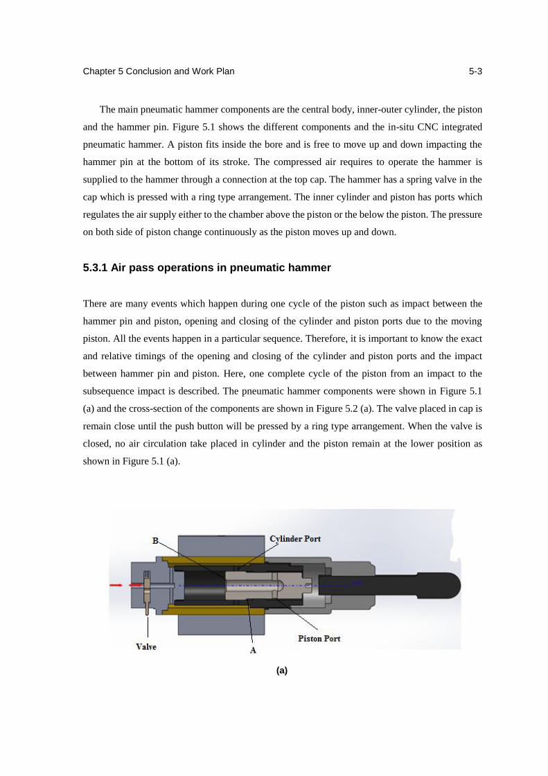
Chapter 5 Conclusion and Work Plan
5-3
The main pneumatic hammer components are the central body, inner-outer cylinder, the piston
and the hammer pin. Figure 5.1 shows the different components and the in-situ CNC integrated
pneumatic hammer. A piston fits inside the bore and is free to move up and down impacting the
hammer pin at the bottom of its stroke. The compressed air requires to operate the hammer is
supplied to the hammer through a connection at the top cap. The hammer has a spring valve in the
cap which is pressed with a ring type arrangement. The inner cylinder and piston has ports which
regulates the air supply either to the chamber above the piston or the below the piston. The pressure
on both side of piston change continuously as the piston moves up and down.
5.3.1 Air pass operations in pneumatic hammer
There are many events which happen during one cycle of the piston such as impact between the
hammer pin and piston, opening and closing of the cylinder and piston ports due to the moving
piston. All the events happen in a particular sequence. Therefore, it is important to know the exact
and relative timings of the opening and closing of the cylinder and piston ports and the impact
between hammer pin and piston. Here, one complete cycle of the piston from an impact to the
subsequence impact is described. The pneumatic hammer components were shown in Figure 5.1
(a) and the cross-section of the components are shown in Figure 5.2 (a). The valve placed in cap is
remain close until the push button will be pressed by a ring type arrangement. When the valve is
closed, no air circulation take placed in cylinder and the piston remain at the lower position as
shown in Figure 5.1 (a).
(a)
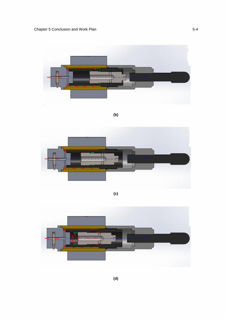
Chapter 5 Conclusion and Work Plan
5-4
(b)
(c)
(d)
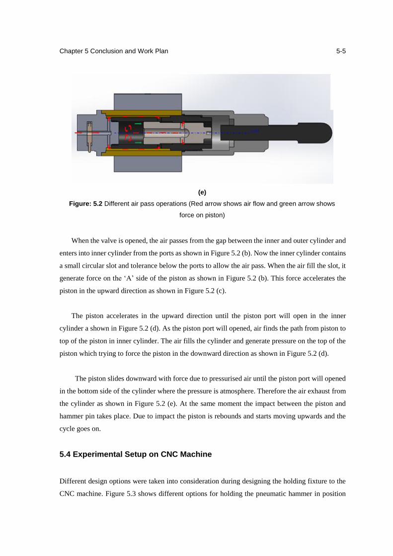
Chapter 5 Conclusion and Work Plan
5-5
(e)
Figure: 5.2 Different air pass operations (Red arrow shows air flow and green arrow shows
force on piston)
When the valve is opened, the air passes from the gap between the inner and outer cylinder and
enters into inner cylinder from the ports as shown in Figure 5.2 (b). Now the inner cylinder contains
a small circular slot and tolerance below the ports to allow the air pass. When the air fill the slot, it
generate force on the ‘A’ side of the piston as shown in Figure 5.2 (b). This force accelerates the
piston in the upward direction as shown in Figure 5.2 (c).
The piston accelerates in the upward direction until the piston port will open in the inner
cylinder a shown in Figure 5.2 (d). As the piston port will opened, air finds the path from piston to
top of the piston in inner cylinder. The air fills the cylinder and generate pressure on the top of the
piston which trying to force the piston in the downward direction as shown in Figure 5.2 (d).
The piston slides downward with force due to pressurised air until the piston port will opened
in the bottom side of the cylinder where the pressure is atmosphere. Therefore the air exhaust from
the cylinder as shown in Figure 5.2 (e). At the same moment the impact between the piston and
hammer pin takes place. Due to impact the piston is rebounds and starts moving upwards and the
cycle goes on.
5.4 Experimental Setup on CNC Machine
Different design options were taken into consideration during designing the holding fixture to the
CNC machine. Figure 5.3 shows different options for holding the pneumatic hammer in position
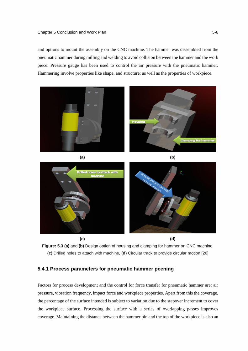
Chapter 5 Conclusion and Work Plan
5-6
and options to mount the assembly on the CNC machine. The hammer was dissembled from the
pneumatic hammer during milling and welding to avoid collision between the hammer and the work
piece. Pressure gauge has been used to control the air pressure with the pneumatic hammer.
Hammering involve properties like shape, and structure; as well as the properties of workpiece.
(a) (b)
(c) (d)
Figure: 5.3 (a) and (b) Design option of housing and clamping for hammer on CNC machine,
(c) Drilled holes to attach with machine, (d) Circular track to provide circular motion [26]
5.4.1 Process parameters for pneumatic hammer peening
Factors for process development and the control for force transfer for pneumatic hammer are: air
pressure, vibration frequency, impact force and workpiece properties. Apart from this the coverage,
the percentage of the surface intended is subject to variation due to the stepover increment to cover
the workpiece surface. Processing the surface with a series of overlapping passes improves
coverage. Maintaining the distance between the hammer pin and the top of the workpiece is also an
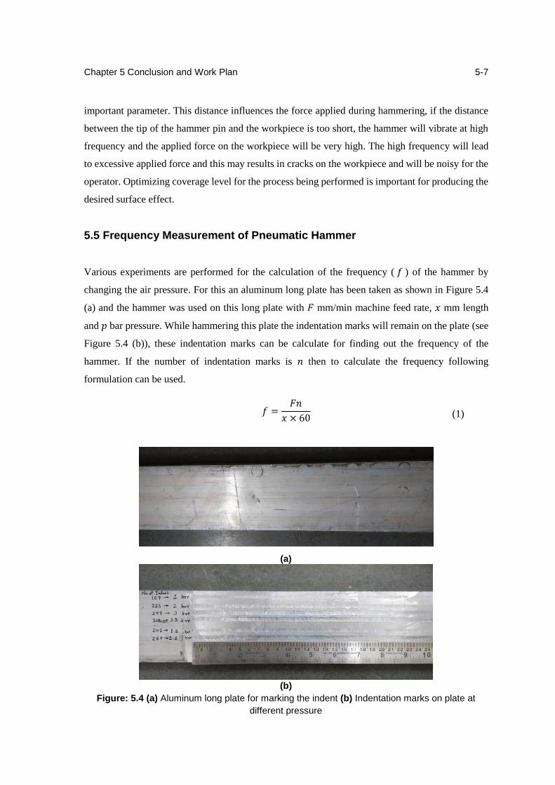
Chapter 5 Conclusion and Work Plan
5-7
important parameter. This distance influences the force applied during hammering, if the distance
between the tip of the hammer pin and the workpiece is too short, the hammer will vibrate at high
frequency and the applied force on the workpiece will be very high. The high frequency will lead
to excessive applied force and this may results in cracks on the workpiece and will be noisy for the
operator. Optimizing coverage level for the process being performed is important for producing the
desired surface effect.
5.5 Frequency Measurement of Pneumatic Hammer
Various experiments are performed for the calculation of the frequency ( 𝑓 ) of the hammer by
changing the air pressure. For this an aluminum long plate has been taken as shown in Figure 5.4
(a) and the hammer was used on this long plate with 𝐹 mm/min machine feed rate, 𝑥 mm length
and 𝑝 bar pressure. While hammering this plate the indentation marks will remain on the plate (see
Figure 5.4 (b)), these indentation marks can be calculate for finding out the frequency of the
hammer. If the number of indentation marks is 𝑛 then to calculate the frequency following
formulation can be used.
(a)
(b)
Figure: 5.4 (a) Aluminum long plate for marking the indent (b) Indentation marks on plate at
different pressure
𝑓 =𝐹𝑛
𝑥 × 60 (1)
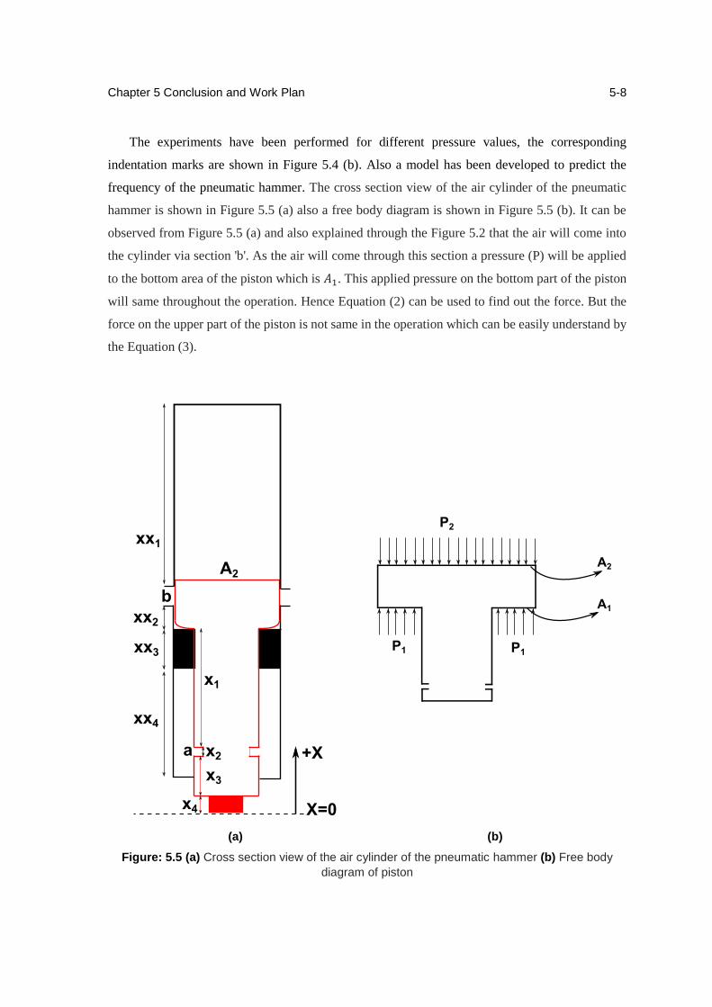
Chapter 5 Conclusion and Work Plan
5-8
The experiments have been performed for different pressure values, the corresponding
indentation marks are shown in Figure 5.4 (b). Also a model has been developed to predict the
frequency of the pneumatic hammer. The cross section view of the air cylinder of the pneumatic
hammer is shown in Figure 5.5 (a) also a free body diagram is shown in Figure 5.5 (b). It can be
observed from Figure 5.5 (a) and also explained through the Figure 5.2 that the air will come into
the cylinder via section 'b'. As the air will come through this section a pressure (P) will be applied
to the bottom area of the piston which is 𝐴1. This applied pressure on the bottom part of the piston
will same throughout the operation. Hence Equation (2) can be used to find out the force. But the
force on the upper part of the piston is not same in the operation which can be easily understand by
the Equation (3).
(a) (b)
Figure: 5.5 (a) Cross section view of the air cylinder of the pneumatic hammer (b) Free body
diagram of piston
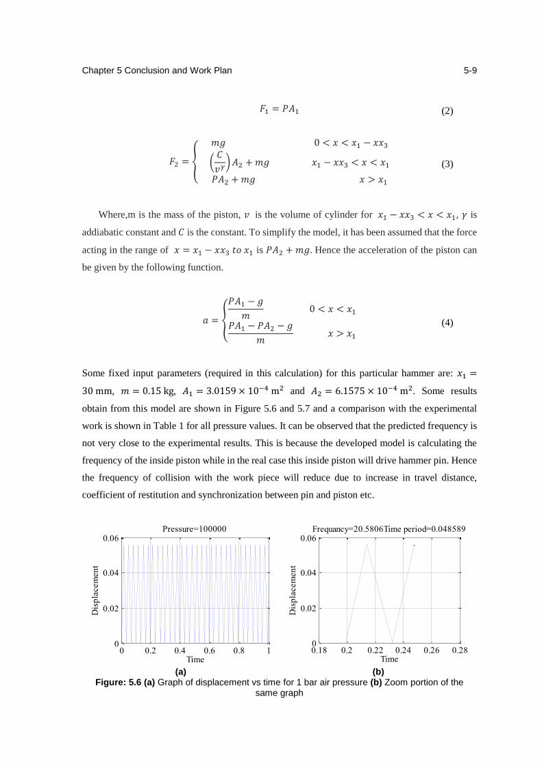
Chapter 5 Conclusion and Work Plan
5-9
Where,m is the mass of the piston, 𝑣 is the volume of cylinder for 𝑥1 − 𝑥𝑥3 < 𝑥 < 𝑥1, 𝛾 is
addiabatic constant and 𝐶 is the constant. To simplify the model, it has been assumed that the force
acting in the range of 𝑥 = 𝑥1 − 𝑥𝑥3 𝑡𝑜 𝑥1 is 𝑃𝐴2 + 𝑚𝑔. Hence the acceleration of the piston can
be given by the following function.
Some fixed input parameters (required in this calculation) for this particular hammer are: 𝑥1 =
30 mm, 𝑚 = 0.15 kg, 𝐴1 = 3.0159 × 10⁻⁴ m2 and 𝐴2 = 6.1575 × 10⁻⁴ m2. Some results
obtain from this model are shown in Figure 5.6 and 5.7 and a comparison with the experimental
work is shown in Table 1 for all pressure values. It can be observed that the predicted frequency is
not very close to the experimental results. This is because the developed model is calculating the
frequency of the inside piston while in the real case this inside piston will drive hammer pin. Hence
the frequency of collision with the work piece will reduce due to increase in travel distance,
coefficient of restitution and synchronization between pin and piston etc.
(a) (b)
Figure: 5.6 (a) Graph of displacement vs time for 1 bar air pressure (b) Zoom portion of the same graph
0 0.2 0.4 0.6 0.8 10
0.02
0.04
0.06
Time
Dis
pla
cem
en
t
Pressure=100000
0.18 0.2 0.22 0.24 0.26 0.280
0.02
0.04
0.06
Time
Dis
pla
cem
en
t
Frequancy=20.5806Time period=0.048589
𝐹1 = 𝑃𝐴1 (2)
𝐹2 = {
𝑚𝑔 0 < 𝑥 < 𝑥1 − 𝑥𝑥3
(𝐶
𝑣𝛾) 𝐴2 + 𝑚𝑔 𝑥1 − 𝑥𝑥3 < 𝑥 < 𝑥1
𝑃𝐴2 + 𝑚𝑔 𝑥 > 𝑥1
(3)
𝑎 = {
𝑃𝐴1 − 𝑔
𝑚 0 < 𝑥 < 𝑥1
𝑃𝐴1 − 𝑃𝐴2 − 𝑔
𝑚 𝑥 > 𝑥1
(4)
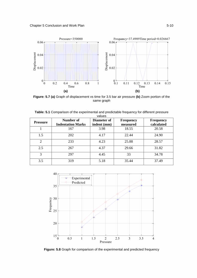
Chapter 5 Conclusion and Work Plan
5-10
(a) (b)
Figure: 5.7 (a) Graph of displacement vs time for 3.5 bar air pressure (b) Zoom portion of the same graph
Figure: 5.8 Graph for comparison of the experimental and predicted frequency
0 0.2 0.4 0.6 0.8 10
0.02
0.04
0.06
Time
Dis
pla
cem
en
t
Pressure=350000
0.1 0.11 0.12 0.13 0.14 0.150
0.02
0.04
0.06
Time
Dis
pla
cem
en
t
Frequancy=37.4989Time period=0.026667
0 0.5 1 1.5 2 2.5 3 3.5 415
20
25
30
35
40
Pressure
Fre
qu
en
cy
Experimental
Predicted
Table: 5.1 Comparison of the experimental and predictable frequency for different pressure values
Pressure Number of
Indentation Marks
Diameter of
indent (mm)
Frequency
measured
Frequency
calculated
1 167 3.98 18.55 20.58
1.5 202 4.17 22.44 24.90
2 233 4.23 25.88 28.57
2.5 267 4.37 29.66 31.82
3 297 4.45 33 34.78
3.5 319 5.18 35.44 37.49
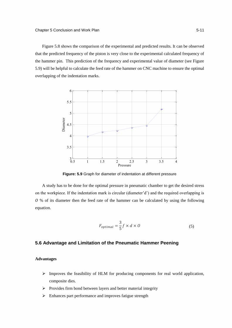
Chapter 5 Conclusion and Work Plan
5-11
Figure 5.8 shows the comparison of the experimental and predicted results. It can be observed
that the predicted frequency of the piston is very close to the experimental calculated frequency of
the hammer pin. This prediction of the frequency and experimental value of diameter (see Figure
5.9) will be helpful to calculate the feed rate of the hammer on CNC machine to ensure the optimal
overlapping of the indentation marks.
Figure: 5.9 Graph for diameter of indentation at different pressure
A study has to be done for the optimal pressure in pneumatic chamber to get the desired stress
on the workpiece. If the indentation mark is circular (diameter’d’) and the required overlapping is
𝑂 % of its diameter then the feed rate of the hammer can be calculated by using the following
equation.
5.6 Advantage and Limitation of the Pneumatic Hammer Peening
Advantages
Improves the feasibility of HLM for producing components for real world application,
composite dies.
Provides firm bond between layers and better material integrity
Enhances part performance and improves fatigue strength
0.5 1 1.5 2 2.5 3 3.5 43
3.5
4
4.5
5
5.5
6
Pressure
Dia
mete
r
𝐹𝑜𝑝𝑡𝑖𝑚𝑎𝑙 =3
5𝑓 × 𝑑 × 𝑂 (5)

Chapter 5 Conclusion and Work Plan
5-12
Limitations
The peening load may transfer to the machine bearings and may cause some problem
May not be applied to complex shapes with internal cavities
Might be a challenge to integrate with 5-axis CNC machine, a complex and rigid support
mechanism may be required
Results not easily predictable because one operator may peen longer than another
5.7 Summary
Residual stresses can damaged the component deposited by HLM process, so some type of
mechanical arrangement has been required to reduce it. So, in-situ CNC integrated pneumatic
hammer which used in RM Lab has been described in this chapter with basic principle, working
operations and its process parameters. Also one model for frequency prediction has been discussed
and compared with experimental frequency in the end of the chapter.
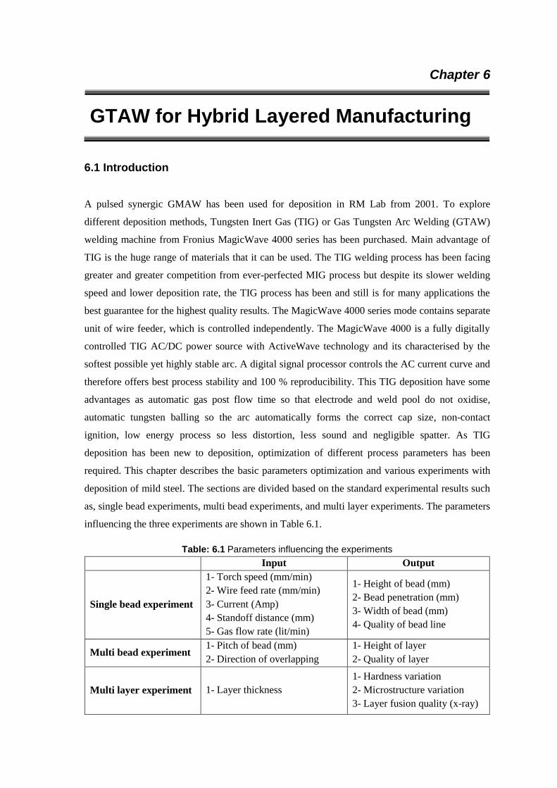
Chapter 6
GTAW for Hybrid Layered Manufacturing
6.1 Introduction
A pulsed synergic GMAW has been used for deposition in RM Lab from 2001. To explore
different deposition methods, Tungsten Inert Gas (TIG) or Gas Tungsten Arc Welding (GTAW)
welding machine from Fronius MagicWave 4000 series has been purchased. Main advantage of
TIG is the huge range of materials that it can be used. The TIG welding process has been facing
greater and greater competition from ever-perfected MIG process but despite its slower welding
speed and lower deposition rate, the TIG process has been and still is for many applications the
best guarantee for the highest quality results. The MagicWave 4000 series mode contains separate
unit of wire feeder, which is controlled independently. The MagicWave 4000 is a fully digitally
controlled TIG AC/DC power source with ActiveWave technology and its characterised by the
softest possible yet highly stable arc. A digital signal processor controls the AC current curve and
therefore offers best process stability and 100 % reproducibility. This TIG deposition have some
advantages as automatic gas post flow time so that electrode and weld pool do not oxidise,
automatic tungsten balling so the arc automatically forms the correct cap size, non-contact
ignition, low energy process so less distortion, less sound and negligible spatter. As TIG
deposition has been new to deposition, optimization of different process parameters has been
required. This chapter describes the basic parameters optimization and various experiments with
deposition of mild steel. The sections are divided based on the standard experimental results such
as, single bead experiments, multi bead experiments, and multi layer experiments. The parameters
influencing the three experiments are shown in Table 6.1.
Table: 6.1 Parameters influencing the experiments
Input Output
Single bead experiment
1- Torch speed (mm/min)
2- Wire feed rate (mm/min)
3- Current (Amp)
4- Standoff distance (mm)
5- Gas flow rate (lit/min)
1- Height of bead (mm)
2- Bead penetration (mm)
3- Width of bead (mm)
4- Quality of bead line
Multi bead experiment 1- Pitch of bead (mm)
2- Direction of overlapping
1- Height of layer
2- Quality of layer
Multi layer experiment 1- Layer thickness
1- Hardness variation
2- Microstructure variation
3- Layer fusion quality (x-ray)
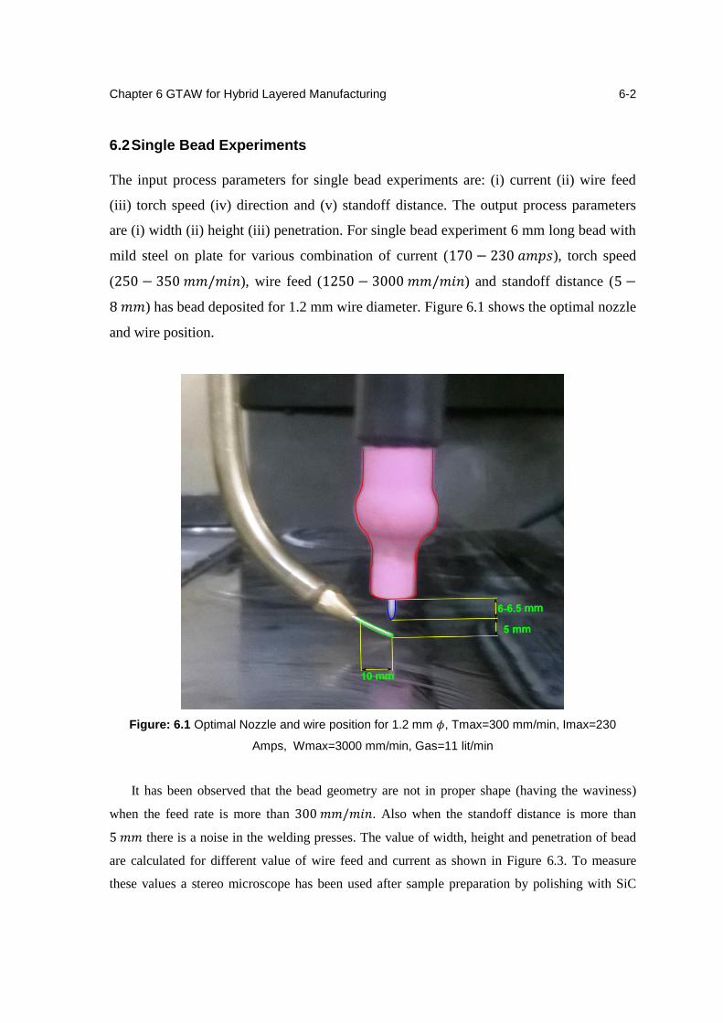
Chapter 6 GTAW for Hybrid Layered Manufacturing
6-2
6.2 Single Bead Experiments
The input process parameters for single bead experiments are: (i) current (ii) wire feed
(iii) torch speed (iv) direction and (v) standoff distance. The output process parameters
are (i) width (ii) height (iii) penetration. For single bead experiment 6 mm long bead with
mild steel on plate for various combination of current (170 − 230 𝑎𝑚𝑝𝑠), torch speed
(250 − 350 𝑚𝑚/𝑚𝑖𝑛), wire feed (1250 − 3000 𝑚𝑚/𝑚𝑖𝑛) and standoff distance (5 −
8 𝑚𝑚) has bead deposited for 1.2 mm wire diameter. Figure 6.1 shows the optimal nozzle
and wire position.
Figure: 6.1 Optimal Nozzle and wire position for 1.2 mm 𝜙, Tmax=300 mm/min, Imax=230
Amps, Wmax=3000 mm/min, Gas=11 lit/min
It has been observed that the bead geometry are not in proper shape (having the waviness)
when the feed rate is more than 300 𝑚𝑚/𝑚𝑖𝑛. Also when the standoff distance is more than
5 𝑚𝑚 there is a noise in the welding presses. The value of width, height and penetration of bead
are calculated for different value of wire feed and current as shown in Figure 6.3. To measure
these values a stereo microscope has been used after sample preparation by polishing with SiC
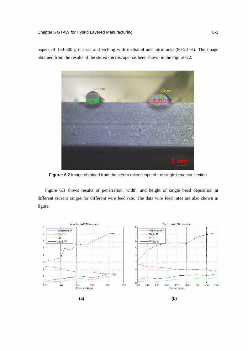
Chapter 6 GTAW for Hybrid Layered Manufacturing
6-3
papers of 150-500 grit sizes and etching with methanol and nitric acid (80-20 %). The image
obtained from the results of the stereo microscope has been shown in the Figure 6.2.
Figure 6.3 shows results of penetration, width, and height of single bead deposition at
different current ranges for different wire feed rate. The data wire feed rates are also shown in
figure.
Figure: 6.2 Image obtained from the stereo microscope of the single bead cut section
(a) (b)
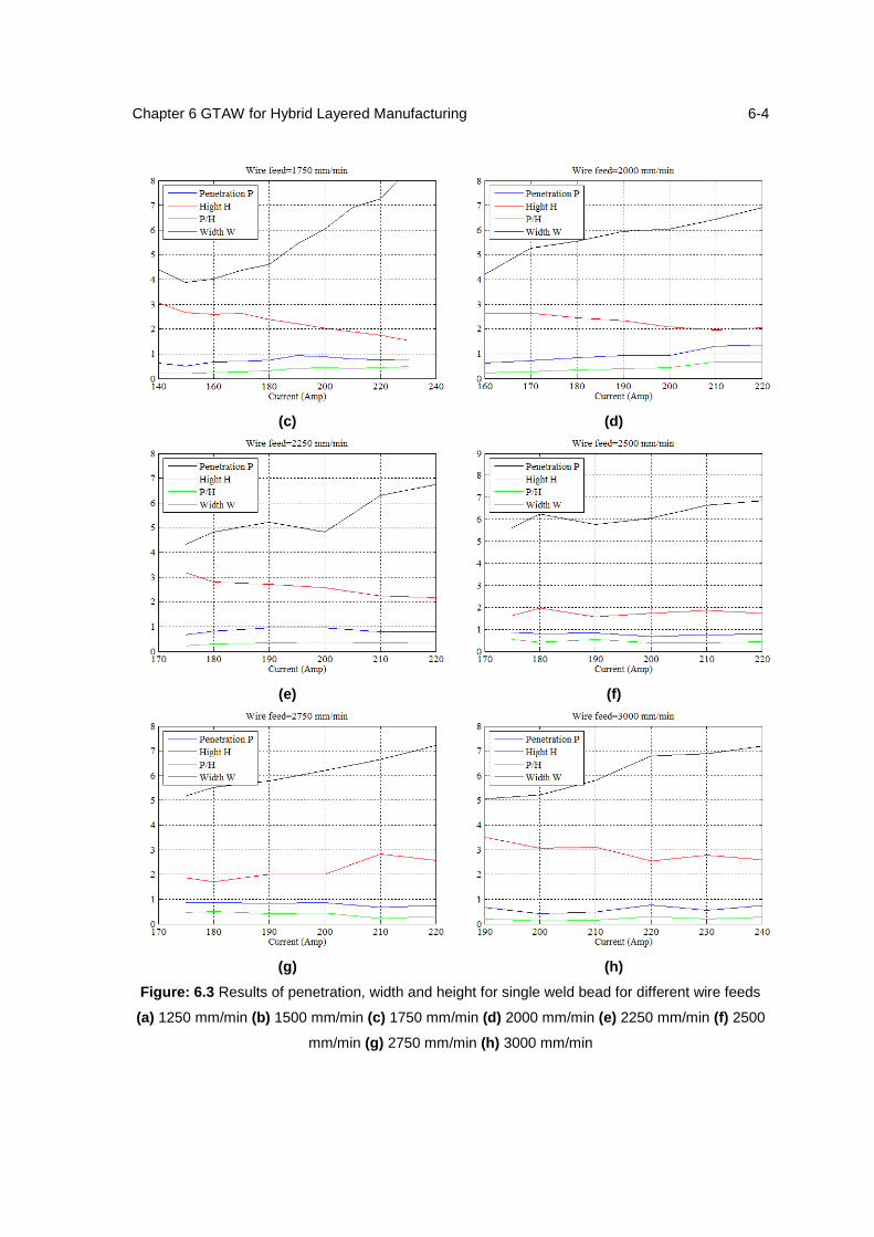
Chapter 6 GTAW for Hybrid Layered Manufacturing
6-4
(c) (d)
(e) (f)
(g) (h)
Figure: 6.3 Results of penetration, width and height for single weld bead for different wire feeds
(a) 1250 mm/min (b) 1500 mm/min (c) 1750 mm/min (d) 2000 mm/min (e) 2250 mm/min (f) 2500
mm/min (g) 2750 mm/min (h) 3000 mm/min
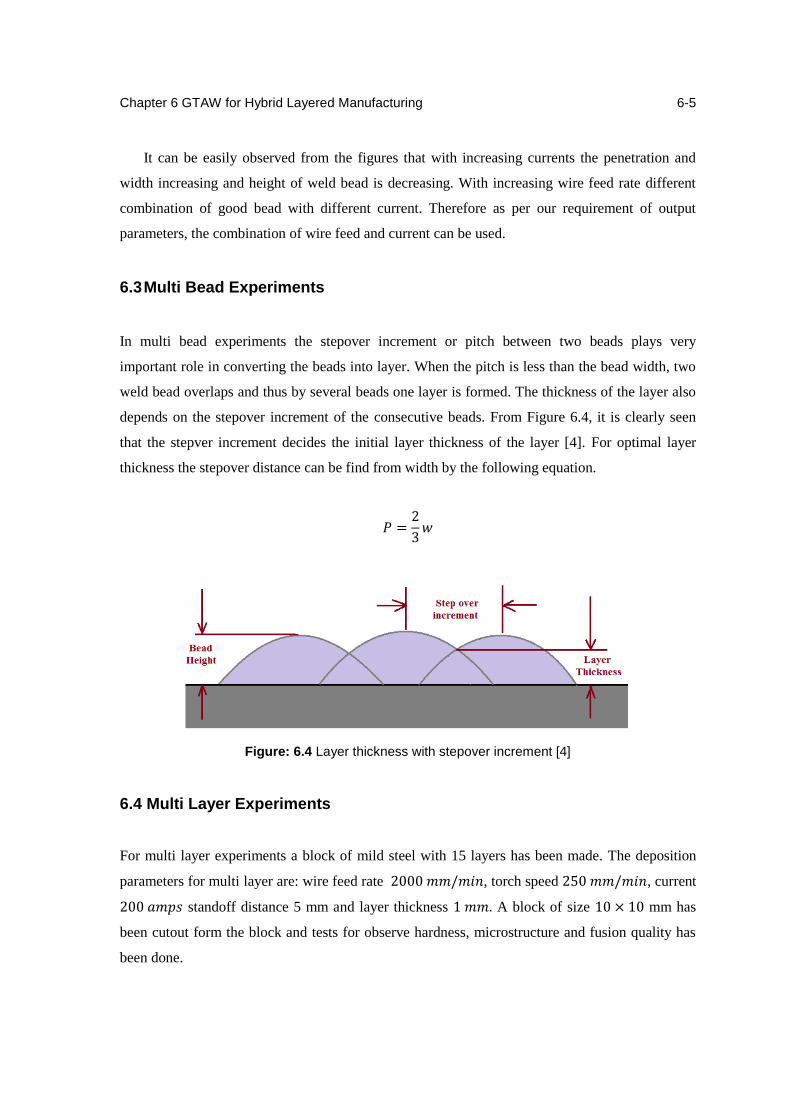
Chapter 6 GTAW for Hybrid Layered Manufacturing
6-5
It can be easily observed from the figures that with increasing currents the penetration and
width increasing and height of weld bead is decreasing. With increasing wire feed rate different
combination of good bead with different current. Therefore as per our requirement of output
parameters, the combination of wire feed and current can be used.
6.3 Multi Bead Experiments
In multi bead experiments the stepover increment or pitch between two beads plays very
important role in converting the beads into layer. When the pitch is less than the bead width, two
weld bead overlaps and thus by several beads one layer is formed. The thickness of the layer also
depends on the stepover increment of the consecutive beads. From Figure 6.4, it is clearly seen
that the stepver increment decides the initial layer thickness of the layer [4]. For optimal layer
thickness the stepover distance can be find from width by the following equation.
𝑃 =2
3𝑤
Figure: 6.4 Layer thickness with stepover increment [4]
6.4 Multi Layer Experiments
For multi layer experiments a block of mild steel with 15 layers has been made. The deposition
parameters for multi layer are: wire feed rate 2000 𝑚𝑚/𝑚𝑖𝑛, torch speed 250 𝑚𝑚/𝑚𝑖𝑛, current
200 𝑎𝑚𝑝𝑠 standoff distance 5 mm and layer thickness 1 𝑚𝑚. A block of size 10 × 10 mm has
been cutout form the block and tests for observe hardness, microstructure and fusion quality has
been done.
Chapter 6 GTAW for Hybrid Layered Manufacturing
6-6
6.4.1 Hardness test
The hardness test has been done on the specimen and the results are shown in Table 6.2. One can
conclude form it that the hardness of topmost layer is more than the bottom most layer.
This is because of the change in the microstructure of the layers hence on account of the
hardness is varying from bottom to top layer.
Table: 6.2 Results of hardness test on the sample
Top Layer
1 85.96
89.91 HRB 2 90.16
3 93.6
Bottom Layer
1 82.31
83.87 HRB 2 85.21
3 84.11
Side Wall (from bottom)
1 82.13
83.29 HRB 2 83.25
3 84.5
6.4.2 Microstructure analysis
The deposited metal by HLM is influenced significantly by the additional thermal cycles induced
by the deposition of subsequent passes. Only the final pass deposited is un-tempered (i.e. has a
primary microstructure). As the microstructure of the build-up comprise of various zones, the
overall properties of the weld metal are expected to be determined by the combination of the
properties of all the different zones. Electron Backscattered Diffraction (EBSD) has been
performed to understand the effect of thermal cycles on microstructure of different layers.
Sample preparation for EBSD
The objective of preparing sample was to obtain high quality electro backscattered diffraction
(EBSD) pattern. The backscattered electrons from the surfaces being characterized form the
EBSD patterns. A high tilt angle of the specimen forms a diffraction region within the top 10-50
nanometers of the specimen. The crystal lattice in this region needs to be strain-free and clean
from contamination or oxide layers for the diffraction to occur. Otherwise, the resulting EBSD
patterns will be of poor quality or will not be visible. Proper specimen preparation addresses these
Chapter 6 GTAW for Hybrid Layered Manufacturing
6-7
issues and helps obtain reliable orientation image microscopy (OIM) data. Both mechanical
polishing and electron polishing were performed to obtain good quality EBSD pattern. The
following steps were followed to prepare a sample for EBSD.
It involve coarse grinding, fine grinding and polishing. Sectioning is a removal of a
representing area from the parent specimen. Grinding removes deformation layer introduced
during sectioning and produces a flat surface for examination. Water was used as a lubricant to
flush away removed material and keep fresh abrasive exposed. During grinding of sample, SiC
papers of grit sizes 240, 400, 1000, 1500 and 2000 was used for about 15 minutes each. Polishing
was used to remove deformation induced earlier during grinding. A general-purpose cloth with
alpha and gamma alumina abrasive, along with diamond solutions were used for polishing.
Diamond polishing using 3 micron diamond solution was performed for 10 minutes.
While mechanical polishing can produce good EBSD patterns, electro polishing was used to
further improve the pattern quality. Electro polishing removes surface material by electrolytic
action. This method removes any remain deformation layers and surface irregularities. To electro
polish, the specimen was made an anode in an electrolytic cell. The anodic film controls the
removal rate during electro polishing. During polishing, the anodic film thickness remains
constant and a planar surface exists between the film and the electrolyte. Voltage and current were
adjusted to maintain the anodic film. Electro polishing of mild steel was performed by keeping
voltage 15 V for 20 s. Solution used for electro polishing was methanol and perchoric acid in
proportion of 80:20. The electro polishing sample was mounted on EBSD machine at an angle of
70° for scanning.
Results
The grain size measurement was carried out on different layers in order to gain a better
understanding of the effect of process parameters on microstructure gradient. The course and fine
regions of the optical microscopy image of the microstructure were captured and average gain
sizes were considered for top, bottom and in between layers. One block of 10 layers was
deposition by TIG deposition HLM with optimum process parameters. Figure 6.5 shows
microstructure for different layers and Table 6.3 shows the average grain sizes.
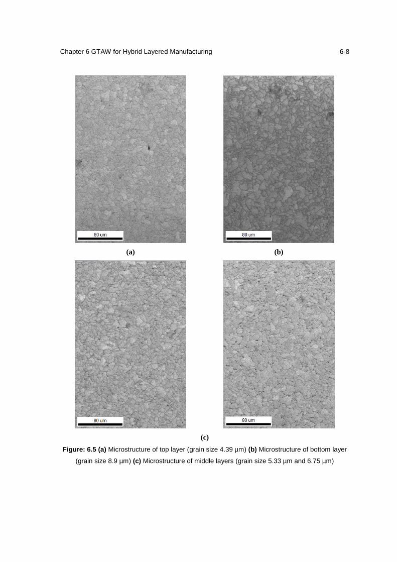
Chapter 6 GTAW for Hybrid Layered Manufacturing
6-8
(a) (b)
(c)
Figure: 6.5 (a) Microstructure of top layer (grain size 4.39 µm) (b) Microstructure of bottom layer
(grain size 8.9 µm) (c) Microstructure of middle layers (grain size 5.33 µm and 6.75 µm)
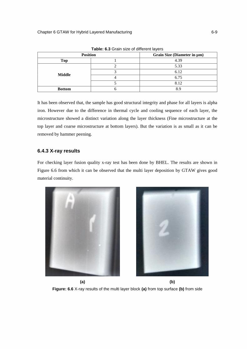
Chapter 6 GTAW for Hybrid Layered Manufacturing
6-9
Table: 6.3 Grain size of different layers
Position Grain Size (Diameter in µm)
Top 1 4.39
Middle
2 5.33
3 6.12
4 6.75
5 8.12
Bottom 6 8.9
It has been observed that, the sample has good structural integrity and phase for all layers is alpha
iron. However due to the difference in thermal cycle and cooling sequence of each layer, the
microstructure showed a distinct variation along the layer thickness (Fine microstructure at the
top layer and coarse microstructure at bottom layers). But the variation is as small as it can be
removed by hammer peening.
6.4.3 X-ray results
For checking layer fusion quality x-ray test has been done by BHEL. The results are shown in
Figure 6.6 from which it can be observed that the multi layer deposition by GTAW gives good
material continuity.
(a) (b)
Figure: 6.6 X-ray results of the multi layer block (a) from top surface (b) from side

Chapter 6 GTAW for Hybrid Layered Manufacturing
6-10
6.5 Directional Problem in GTAW Deposition
GTAW deposition gives some problematic results when the wire follows torch with tungsten
electrode. When a circle has been deposited the thickness of the circle should be uniform but the
thickness of the circle was not uniform which shown the Figure 6.7. The deposition gives
offset bead when the wire follow torch in the circle. Two circular patterns has been
deposition with standoff distance 5 mm and 7 mm. Even there was noise while depositing
with standoff distance 7 mm but the circle was at least completed without any groove cut
into it which was observed with standoff distance 5 mm. The width and height of the
circular bead has been shown in Figure 6.8 by dividing the circle in equidistance parts.
(a) (b)
Figure: 6.7 (a) Standoff distace 5 mm which is optimal (b) standoff distance 7mm
Figure: 6.8 Height and width of circular weld bead at different points

Chapter 6 GTAW for Hybrid Layered Manufacturing
6-11
6.6 Summary
It this chapter new GTAW deposition for HLM has been discussed. The effect of input and out
process parameters on basic single bead, multi bead and multi layer experiments have been
discussed. The results of hardness test, microstructure analysis and fusion quality are shown. The
direction problem in GTAW deposition is also discussed in the end of the chapter.
Chapter 7
Conclusion and Future Scope
5.1 Conclusion
In an undercut/overhang free geometry, 2.5 axis kinematics is enough for deposition as
the current layer always lies within the extents of the previous one. While building a
geometry with undercuts, if the current layer overhangs the previous one beyond a limit,
the material flows down before it solidifies. To avoid this problem, one can suitably tilt
the substrate using a 5-Axis kinematics.
During 5-Axis deposition, the torch vector at a point on a loop can be calculated as the
cross product of the surface normal vector at that point on the object and the direction
vector. This method can be used when the surface normal data is easily available. When
the surface normal data cannot be simply accessed, one can still approximate the torch
vector using the Double Slice method.
The feature based conformal AM can fabricate the complex geometries without using any
support mechanism, the capability was proved by taking an example of complex IC-7
housing part. If we can find combination of U and V direction toolpath then the lifts will
be reduce.
Instead of base metal plate, if we use integral substrate then the strength of the component
can be increase and material used can be reduced. In the example of turbine blade the
efficiency of this process was 68.29 % calculated.
Preheating, stress relieving and inspection are required for tool steel and exotic
materials (Ni and Tin alloys) components. Due to unavailability of workspace and
various defects problem, the integrated multi-station HLM is require.
The given frequency prediction model for pneumatic model is found to be in good
agreement with the experimental results. The prediction of frequency can be used to find
out the optimal feed ate of hammer.
Chapter 5 Conclusion and Work Plan
5-2
The bead quality obtained in GTAW is found better as compare to GMAW. The process
is spatter less and noise less. Hardness test, microstructure analysis and x-ray test are
giving satisfactory and predicted results. On the other hand it is also observed that the
deposition rate in GTAW is lesser as compared to the GMAW. Also there is a directional
issue with this process as the wire is not feeding from the central position.
5.2 Future Scope
The toolpath strategy for filling the cylindrical part in featured based method has to be
improve by reducing lifts. The complex IC-7 housing part has to be deposited by this
method to prove the capability of the method.
Currently, the integral substrate method has been tried directly to build turbine blade.
Hence it is required to explore a good literature review related to this method.
The process can be explored for deposition of exotic materials such as Inconel and Ti-
alloy.
Stress prediction model can be developed for pneumatic hammering and experiments can
be performed.
The direction issue can be overcome by installing a rotating wire feeder.
References
1. C. K. Chua, K. F. Leong, and C. S. Lim., "Rapid Prototyping - Principles and Applications (2nd
Edition)", World Scientific Publishing Co. Pte. Ltd., 2003.
2. Trevor Boehm, Maria-Isabel Carnasciali, M. Elizabeth Douglas, Marco Gero Fernandez, and
Christopher Williams,"Rapid prototyping industry analysis. Technical report", Georgia
Institute of Technology, 2004.
3. K. P. Karunakaran, S. Suryakumar, Vishal Pushpa, and Sreenathbabu Akula, "Low cost
integration of additive and subtractive processes for hybrid layered manufacturing", Robotics
and Computer-Integrated Manufacturing, Vol. 26 (5), 490 - 499, 2010.
4. Suryakumar S., "Investigations into Hybrid Layered Manufacturing of Metallic Objects", PhD
dissertation, Indian Institute of Technology, Bombay, 2009.
5. Blackwell P. and Wisbey A., "Laser-aided manufacturing technologies; their application to the
near-net shape forming of a high-strength titanium alloy”, Journal of Materials Processing
Technology, Vol. 170 (1-2), 268-276, 2005.
6. Domack M. and Baughman J., "Development of nickel-titanium graded composition
components", Rapid Prototyping Journal, Vol. 11 (1), 41-51, 2005.
7. Kobryn P. et al., "Rapid Fabrication of Replacement Components via Laser Additive
Manufacturing of Titanium", in 6th Joint FAA, NASA Aging Aircraft Conference, 2002.
8. B. Yashwanth Kumar, "5-axis hybrid manufacturing for metallic objects", Master's thesis,
Department of Mechanical Engineering, Indian Institute of Technology, Bombay, 2012.
9. Horii T., Kirihara S., and Miyamoto Y., "Freeform fabrication of Ti-Al alloys by 3D micro-
welding", Intermetallics, Vol. 16 (11-12), 1245-1249, 2008.
10. Horii T., Kirihara S., and Miyamoto Y., "Freeform fabrication of superalloy objects by 3D
micro welding", Materials & Design, Vol. 30 (4), 1093- 1097, 2009.
11. Song Y. and Park S., "Experimental investigations into rapid prototyping of composites by
novel hybrid deposition process", Journal of Materials Processing Technology, Vol. 171 (1),
35-40, 2006.
12. Kovacevic R. and Beardsley H., "Process Control of 3D Welding as a Droplet-Based Rapid
Prototyping Technique", In Proceedings of Solid Freeform Symposium. 55-64, 1998.
13. Lincoln Electric, "GMAW Welding Guide", available at:
www.content.lincolnelectric.com/pdfs/products/literature/c4200.pdf., 2009.
References
R-2
14. Fronius, "CMT: The new revolution in digital GMA welding", available at: www.fronius.com,
2009.
15. L. E. Weiss, R. Merz, F. B. Prinz, G. Neplotnik, P. Padmanabhan, L. Schultz, and K.
Ramaswami,"Shape deposition manufacturing of heterogeneous structures", Journal of
Manufacturing Systems, Vol. 16 (4), 239 - 248, 1997.
16. K. P. Karunakaran and Alain Bernard, "Variable axis additive manufacturing of metallic
objects", In European Forum on Additive Manufacturing, 18th Edition, 2013.
17. Y. M. Zhang, Y. Chen, P. Li, and A. T. Male, "Weld deposition-based rapid prototyping: a
preliminary study", Journal of Materials Processing Technology, Vol. 135 (2-3), 347-357,
2003.
18. Anjan Murmu, "5-axis additive manufacturing of complex metallic objects", Master's thesis,
Department of Mechanical Engineering, Indian Institute of Technology, Bombay, 2013.
19. Prathamesh Joshi, "Algorithms for 5-axis Hybrid Manufacturing", Master's thesis, Department
of Mechanical Engineering, Indian Institute of Technology, Bombay, 2014.
20. Vahid Fallah, Masoud Alimardani, Stephen F. Corbin, Amir Khajepour, “Impact of localized
surface preheating on the microstructure and crackformation in laser direct deposition of Stellite
1 on AISI 4340 steel”, Journal of Applied Surface Science 257,1716–1723,2010.
21. Masoud Alimardani, Vahid Fallah, Amir Khajepour, Ehsan Toyserkani, “The effect of
localized dynamic surface preheating in laser cladding of Stellite 1”, Journal of Surface &
Coatings Technology 204, 3911–3919, 2010.
22. Y.C. Lin, S.C. Chen, “Effect of residual stress on thermal fatigue in a type 420 martensitic
stainless steel weldment”, Journal of Materials Processing Technology 138, 22–27, 2003.
23. Xiaohua Cheng, John W. Fisher, “Residual stress modification by post-weld treatment and its
beneficial effect on fatigue strength of welded structures”, International Journal of Fatigue 25,
1259–1269, 2003
24. Shigeru Aoki, Tadashi Nishimura, Tetsumaro Hiroi, Seiji Hirai, “Reduction method for residual
stress of welded joint using harmonic vibrational load”, Journal of Nuclear Engineering and
Design, 2006.
25. Jijin Xu, Ligongc Chen, Chunzhen Ni, “A study on the mechanical stress relieving and safety
assessment without post-weld hat treatment”, Journal of Material Science and Engineering,
2006.
26. Tadesse Billo, “Characterization and improvement of additive manufacturing”, Master's thesis,
Department of Mechanical Engineering, Indian Institute of Technology, Bombay, 2012.

Acknowledgement
I take this opportunity to express my deep sense of indebtedness to my guide Prof. K. P.
Karunakaran for allowing me to work, under their supervision and for their valuable guidance
and encouragement throughout the course of my project work.
I am also grateful to all faculty members at IIT Bombay for their encouragement and support.
Special thanks to Prof. Indradev S. Samajdar and technical staff in OIM lab, SAIF and Machine
tool lab of IIT Bombay for their continuous and kind assistance.
I greatly appreciate the support of Mr. Rony for helping me in the mechanical operation of CNC
machine and Mr. Sajan Kapil for giving me his important time throughout my project work. I
would also like to thank my all lab mates and interns who have always extended their support to
me.
Finally, I would like to acknowledged my family members, the love and support of my Mother
not just during my M.Tech, but throughout my life and my Father for his enthusiasm in seeing
me get a masters; it will not be wrong if I say he is more happy than me about completion of my
masters. I would like to extend special thanks to my Sister for her constant support and
encouragement during my work
Ankit Desai
(Roll No. 133100069)