annual preventive maintenance instructions - medivators · 2016-07-25 · 1 annual preventive...
TRANSCRIPT

1
Annual Preventive Maintenance Instructions
These instructions should followed to perform preventive maintenance on the ADVANTAGE PLUS and ADVANTAGE PLUS 2.0 (serial number 65018001 and higher) reprocessors.
Before commencing work on the reprocessor, ensure that you have the appropriate parts, tools and PPE.
Parts Required
78400-346 ADVANTAGE PLUS Annual PM Kit
78400-776 ADVANTAGE PLUS Annual PM Kit for reprocessors without the MEDIVATORS Compressor
PM Kit Parts Content
PART DESCRIPTION PART NUMBER QTY
ADVANTAGE PLUS PM Instructions 50097-003 1
Air Filter MF01-0028 4
Alcohol/Detergent Pump Head 3-5-151 4
Alcohol/Detergent Pump Head Wire Tie CT05-0000 10
Alcohol/Detergent Uptake Check Valve MV01-0040 2
Basin Connector O-ring 3-8-110 16
Basin Drain Filter 3-9-420 2
Channel Pump 78399-987 2
Compressor Service Kit (only 78400-346) 3-9-452 1
Dosing Assembly Ball 47049-658 4
Dosing Assembly Ball Spring 47049-415 4
Dosing Assembly O-ring 43100-302 28
Dosing Supply Braided Tubing 47509-439 2 feet (61 cm)
Dosing Supply Check Valve 3-4-133 4
Dosing Supply Check Valve Clamp 37590-204 8
Elevator Pump Diaphragm 43100-343 2
Sample Port O-ring 43100-152 2
Sample Port Poppet Spring 41008-011 2
Sample Port Poppet Valve 41600-217 2
Sample Port Valve 41600-391 2
Silicone Oil 17599-496 1
Spray Arm Gasket 43100-111 2
Spray Arm Lid Gasket 43100-214 2
Spray Arm Nut O-ring 43100-113 2
Spray Arm O-ring 43100-253 2
Spray Arm Pump 78399-988 2
Spray Head Bearing 3-7-130 22
Spray Head Gasket 43100-322 2
Spray Head Gasket 43100-324 2

2
Annual Preventive Maintenance Instructions
Tools Required
Philips screwdriver
Straight blade screwdriver
2.5mm Allen wrench
3/8” Allen wrench
Needle nose pliers
Tubing cutter
Pliers
7mm nut driver
Wire cutters
Adjustable wrench
Silicone oil (included)
Manometer
Bucket, 1-2 gallons
Procedure
Purging the ADVANTAGE PLUS Reprocessor of Fluids 1. Ensure both lids are closed with a machine disinfection block in each basin.
2. Place Part A and B uptake tubes together into a 1 to 2 gallon bucket filled with warm water.
3. In Expert mode activate P0E and P0H on the left and right basin, let the pumps run until fluid stops coming out of the three stream spout. Be sure to keep the lids closed, chemistry is beings dispensed.
4. Press Release All.
5. In Expert mode activate P0F and P0G for the left basin, let the pumps run until fluid starts entering the bucket through the overflow lines in the uptake tubes.
6. In Expert mode activate P0E and P0H for the left basin, keeping P0F and P0G running.
7. Allow the pumps to run until the bucket is empty and fluid stops entering the basin.
8. Press Release All.
9. Repeat steps 5 through 8 for the right basin.
10. Remove the Alcohol and Detergent containers.
11. In Expert mode activate Y11, Y10, P0Z and P0C for the left and right basin.
12. Once the lines are purged press Release All.
13. In Expert mode activate Y90 and Y02 for both the left and right basin; once water enters the basin activate P0J to rinse the basins.

3
Annual Preventive Maintenance Instructions
14. After 1 minute press Release All.
15. In Expert mode activate P0J, P0A Channels (2) and Y01 for both the left and right basin to purge the spray arm and channel pumps of fluid.
16. After 1 minute press Release All.
17. Shutdown the computer using the Shutdown option in the Start menu.
18. Power down the ADVANTAGE PLUS reprocessor and turn off the air and water.
19. Remove the blue plastic access panels on the left and right sides.
Note: While performing the PM check for internal and external fluid leaks.
Channel Pump 1. Performed on both sides.
2. Remove the two white John Guest elbow fittings from the pump assembly by pressing in on the gray collar.
3. Make note of the tubing locations.
4. Disconnect the electrical connection.
5. Remove the four Philips head screws that attach the pump to the mounting bracket.
6. Remove the old pump and discard.
7. Place the new pump (78399-987) on the mounting bracket and reattach with the four screws.
8. Reconnect the electrical connection.
9. Reconnect the fittings making sure they are connected to the original locations.
Figure 1: Channel Pump

4
Annual Preventive Maintenance Instructions
Figure 2: Channel Pump (ADVANTAGE PLUS 2.0 System)
Spray Arm Pump 1. Performed on both sides.
2. Remove the two fittings from the top of the spray arm pump assembly by pulling down on the two tabs located just below the elbow fittings. Note the fitting locations.
3. Disconnect the electrical connection.
4. Remove the four nuts/screws and washer that attach the base of the assembly to the unit, save for reassembly.
5. Remove the old pump and discard.
6. Place the new pump (78399-988) onto the mounting bracket and reattach with the nuts and washers.
7. Reconnect the fittings again noting the original locations. Lock in place by pressing up on the tabs.
8. Reconnect the electrical connection.

5
Annual Preventive Maintenance Instructions
Figure 3: Spray Arm Pump

6
Annual Preventive Maintenance Instructions
Figure 4: Spray Arm Pump (ADVANTAGE PLUS 2.0 System)
Elevator Pump Diaphragm 1. Performed on both sides.
2. The elevator pump is located on the back side of the channel manifold.
3. Remove the 4 Allen screws with a 2.5mm Allen wrench.
4. Remove the circular assembly from the manifold.
5. Remove and discard the old diaphragm.
6. Place the new diaphragm (43100-343) in the channel manifold. When properly placed a small hole should be visible in the center of the diaphragm.
7. Place the circular assembly back in its original position and reattach with the four Allen screws.

7
Annual Preventive Maintenance Instructions
Figure 5 and 6: Elevator Pump Diaphragm

8
Annual Preventive Maintenance Instructions
Figure 7: Elevator Pump Diaphragm (ADVANTAGE PLUS 2.0 System)
Sample Port Valve 1. Performed on both sides.
2. The sample port valve is accessed from the back of the unit and will be in one of two possible locations. For units with serial numbers 65902224 and lower the sample port valve will be mounted to the frame towards the top of the unit (unless converted). For units with serial numbers 65902225 and higher the sample port valve will be physically attached to the blue coiled valves labeled Y14 or Y16.
3. To gain access to the sample port valve attached to valve Y14 or Y16 remove the two Phillips screws that are either to the left or the right of the spray arm pump mounting plate. Once the screws are removed the mounting plate containing Y14 /Y16 can be lifted to gain access to the sample port valve.
4. To remove the sample port valve, first remove the electrical connector from the valve coil using a flat blade screwdriver. Next remove the large nut holding the coil to the valve body. Once the coil has been removed the four Allen screws holding the valve to the gray manifold can be removed using a 2.5mm Allen wrench, save the screws.
5. Discard the old valve.
6. Inspect the gray manifold ensuring there are not any o-rings left in the manifold and the surface is clean.
7. Install the new sample port valve (41600-391) ensuring the o-rings are in the proper locations. Lightly lubricate the o-rings. Reattach the electrical connection.
8. If applicable reattach the mounting plate taking care not to pinch the wires coming from the air purge valve (Y0H) mounted on the same plate. Secure with the two screws.

9
Annual Preventive Maintenance Instructions
Figure 8: Sample port valve locations
Figure 9: Y14/Y16 mounting plate screws
Serial number 65902224 and lower
Serial number 65902225 and higher

10
Annual Preventive Maintenance Instructions
Figure 10: Sample port valve location on the Y14/Y16 assembly
Figure 11: Sample port valve location on the frame

11
Annual Preventive Maintenance Instructions
Alcohol and Detergent Pump Head 1. Performed on both sides.
2. Use wire cutters to remove the tie wraps from the tubing connections on the manifold.
3. Remove the tubing from the barb fittings. Make note of the tubing positions.
4. Remove the old pump head by pressing in on the two black plastic tabs and firmly pull down. Discard the old pump heads.
5. Place the new pump head (3-5-151) on the motor assembly and press up firmly making sure it snaps firmly in place. Note the orientation of the tubing.
6. The new tubing on the pump head will need to be cut to match the tubing length removed to ensure no kinking of the tubing.
7. Connect the new tubing to the barbed fittings on the manifold again noting the original locations.
8. Use the supplied wire ties (CT05-0000) to secure the tubing on the barbed fittings.
Figure 12: Sample port valve o-ring location

12
Annual Preventive Maintenance Instructions
Figure 13: Alcohol and Detergent Pump Head
Figure 14: Alcohol and Detergent Pump Head (ADVANTAGE PLUS 2.0 System)

13
Annual Preventive Maintenance Instructions Dosing Supply Check Valves
1. Performed on both sides.
2. The two check valves are located directly behind the spray arm pump.
3. Replace on check valve at a time to maintain proper connection.
4. Cut the tubing above and below the clamps, remove and discard the old check valve.
5. Place the new check valve (3-4-133) in place of the old, the flow direction arrow on the new check valve must point up.
6. Clamp the tubing on the check valve using the supplied clamps (37590-204).
7. Repeat the above steps for the other check valve.
NOTE: After repeated PMs the upper braided tubing will become too short. If that is the case use the supplied braided tubing (47509-439) to bring them back to their original length of 6 inches.
Figure 15: Dosing Supply Check Valves
Dosing Assembly 1. Remove the metal cover behind the alcohol and detergent container held in place by 8 Phillips head
screws.
2. Remove the 4 Phillips head screws holding the sample port, alcohol/detergent uptake bracket in place. Do not remove the bracket.
3. Remove the 4 Phillips head screws holding the dosing assembly in place. These are located beneath the dosing assembly.
4. Disconnect the tubing and electrical connections from the back side of the dosing assembly.
5. Remove the dosing assembly from the machine.

14
Annual Preventive Maintenance Instructions
6. Remove the 12 o-rings on the reservoir connections and discard. Replace with 12 new o-rings (43100-302).
7. Remove the 4 or 8 Phillips head screws holding the cover on the dosing assembly.
8. Remove the pumps one at time and replace the two o-rings (43100-302). To remove the pump, disconnect the electrical connection on the board and remove the pin holding the pump in place. Once the pump is removed the o-rings may be attached to the pump or the reservoir, discard the o-rings. Place the new o-rings on the pump and reattach the pump to the assembly.
9. When removing every other pump a spring and ball will be seen in the top of the reservoir. Discard the spring and ball and replace with a new spring (47049-415) and ball supplied (47049-658), there are four total.
10. Once all the o-rings, springs and balls have been replaced make sure the circuit board(s) is firmly seated and reinstall the stainless cover on the dosing assembly.
11. Place the assembly back in the ADVANTAGE PLUS reprocessor. Reconnect all the tubing connections. Note that the connections are keyed so they can only go in one location. Reconnect the electrical connections; they will differ based on the type of machine.
12. Reattach the dosing assembly to the ADVANTAGE PLUS reprocessor using the 4 Phillips screws removed earlier.
13. Do not install the bracket and cover at this time.
Figure 16: Metal Cover removal

15
Annual Preventive Maintenance Instructions
Figure 17: Sample port, alcohol/detergent uptake bracket removal. Dosing Assembly removal
Figure 18: Tubing and electrical connections (ADVANTAGE PLUS 2.0 System)

16
Annual Preventive Maintenance Instructions
Figure 19: Electrical connections (ADVANTAGE PLUS Reprocessor)
Figure 20: O-rings on reservoir connections

17
Annual Preventive Maintenance Instructions
Figure 21: Dosing pump retention pin
Figure 22: Pump o-rings, ball and spring

18
Annual Preventive Maintenance Instructions
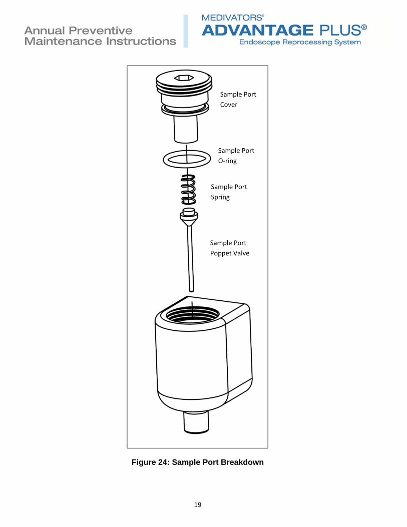
Sample Port 1. Performed on both left and right side sample ports.
2. Using a 3/8” Allen wrench, remove the sample port cover by unscrewing counterclockwise.
3. Once the sample port cover is removed, remove and discard the sample port cover o-ring, the sample port spring and the sample port poppet valve. Note: Earlier sample port poppet valves were a two piece design requiring the removal of the extension before removing the poppet valve from the sample port body. The extension is easily removed by pulling down on the extension. The extension will not be reused.
4. Install the new sample port cover o-ring (43100-152), the sample port spring (41008-011) and the sample port poppet valve (41600-217). Only the sample port cover o-ring requires lubricant.
5. Install the sample port cover so it is flush with the top of the sample port housing.
6. Reattach the sample port, alcohol/detergent bracket.
7. Reattach the metal cover behind the alcohol and detergent containers.
Figure 23: Sample Ports
19
Annual Preventive Maintenance Instructions
Figure 24: Sample Port Breakdown
Sample Port
Cover
Sample Port
O‐ring
Sample Port
Spring
Sample Port
Poppet Valve

20
Annual Preventive Maintenance Instructions
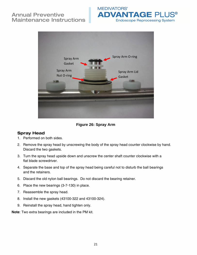
Spray Arm 1. Performed on both sides.
2. Remove the spray arm from the lid by unscrewing the nylon nut.
3. Once removed replace the spray arm o-ring (43100-253), spray arm gasket (43100-111), the spray arm lid gasket (43100-214) and spray arm nut o-ring (43100-113). Only the spray arm lid gasket and spray arm nut o-ring should be lubricated.
4. Reattach the spray arm to the lid.
Figure 25: Spray Arm
21
Annual Preventive Maintenance Instructions
Figure 26: Spray Arm
Spray Head 1. Performed on both sides.
2. Remove the spray head by unscrewing the body of the spray head counter clockwise by hand. Discard the two gaskets.
3. Turn the spray head upside down and unscrew the center shaft counter clockwise with a flat blade screwdriver.
4. Separate the base and top of the spray head being careful not to disturb the ball bearings and the retainers.
5. Discard the old nylon ball bearings. Do not discard the bearing retainer.
6. Place the new bearings (3-7-130) in place.
7. Reassemble the spray head.
8. Install the new gaskets (43100-322 and 43100-324).
9. Reinstall the spray head, hand tighten only.
Note: Two extra bearings are included in the PM kit.
Spray Arm O‐ring
Spray Arm Lid
Gasket
Spray Arm
Gasket
Spray Arm
Nut O‐ring

22
Annual Preventive Maintenance Instructions
Figure 27: Spray head removal.
Figure 28: Spray head center shaft removal.

23
Annual Preventive Maintenance Instructions
Figure 29: Spray head ball bearings and retainers.

24
Annual Preventive Maintenance Instructions
Alcohol and Detergent Uptake Check Valves 1. Remove the alcohol and detergent containers.
2. Remove the old check valves out of the bottom of the uptake tubes, discard.
3. Replace with new check valves (MU01-0040), press into place.
4. Replace the alcohol and detergent containers.
Figure 30: Alcohol and Detergent Uptake Check Valves

25
Annual Preventive Maintenance Instructions
Spray Arm Filter 1. Performed on both sides.
2. Located to the left of the drain manifold.
3. Unscrew the cap counter clockwise, fluid will be present.
4. Remove the screen and clean, the screen is not replaced.
5. Place cleaned screen back in the housing.
6. Reattach the cap; ensure the red seal is in place in the cap.
Figure 31: Spray Arm Filter

26
Annual Preventive Maintenance Instructions
Basin Connector O-rings 1. Performed on both sides.
2. Replace the 8 o-rings (3-8-110) on the basin connector posts.
3. Lightly lubricate each o-ring with silicone oil.
Basin Drain Filter 1. Performed on both sides.
2. Replace the basin drain filter (3-9-420) located in basin drain.
Air Filter 1. Performed on both sides.
2. Replace the air filter (MF01-0028), 2 located on each side.

27
Annual Preventive Maintenance Instructions
Air Compressor
Use PM Kit 78400-346.
Note: Skip this step if the ADVANTAGE PLUS reprocessor unit being serviced does not use the MEDIVATORS air compressor.
Unplug the power from the compressor. Vent the air tank by pulling the pressure relief ring located underneath the pressure switch.
Air Intake Filters 1. Remove the two air filters located on the top of the compressor by unscrewing counter
clockwise. Discard the old filters and install the two new filters.
5μm Filter 1. Unscrew the lower housing of the 5μm filter.
2. Remove the old filter by unscrewing it and replace with the new filter.
3. Replace the housing o-ring with the supplied o-ring and lubricate with silicone oil.
4. Replace the lower housing, hand tighten only.
Check Valve 1. Locate the check valve assembly underneath the pressure switch.
2. Remove the two braided stainless steel hoses from the end of the check valve by loosening the two fittings.
3. Unscrew the check valve housing; the base of the housing will stay on the air tank.
4. Carefully remove the housing noting the order of the internal parts.
5. Clean and inspect the inside of the housing.
6. Disassemble the new check valve and replace the internal parts of the old check valve with the internal parts of the new check valve. Ensure all pieced go back in the proper order.
7. Reattach the check valve housing to the air tank.
8. Reattach the two braided stainless steel tubing.
Note: When the compressor is repowered check for leaks.
Note: The kit includes a 0.1μm filter kit which is only used on the older style compressor. The filter replacement procedure is the same as the 5μm filter noted above.

28
Annual Preventive Maintenance Instructions
Figure 32: Air Compressor
Figure 33: Air Compressor Check Valve
5µm Filter
Air Filters
Check Valve

29
Annual Preventive Maintenance Instructions
Plug the ADVANTAGE PLUS reprocessor power back in, turn on the water, turn on the air and restart the computer.
Pressure Sensor Testing and Calibration
ADVANTAGE PLUS and ADVANTAGE PLUS 2.0 System Pressure Sensor Testing
There are a total of ten pressure sensors per basin, eight on the channel manifold and two on the alcohol & detergent manifold. There are two switching points that must be checked for each pressure sensor in the LIO Expert Mode:
Upper level: Moment of switching on as pressure is increased, sensor high in LIO.
Lower level: Moment of switching off as pressure is decreased, sensor low in LIO.
Verify the pressure sensor switching points as follows:
1. Connect the manometer to the appropriate channel.
2. Increase the pressure using the manometer and verify the pressure level for sensor activation (the higher value) according to table 1.
3. Slowly decrease pressure on the manometer and verify the pressure level for sensor deactivation (the lower value) according to table 1.
4. If a pressure sensor is out of tolerance perform the calibration procedure.
Table 1
Pressure Sensor Switching Points Notes
S11 Leak Test 60 - 50 mmHg
S06 Jet 120 - 100 mmHg
S05 Biopsy 50 - 40 mmHg
S04 Air 120 - 100 mmHg
S07 Suction 50 - 40 mmHg
S08 Water 120 - 100 mmHg
S09 Extra 50 - 40 mmHg
S10 Elevator 280 - 220 mmHg Activate Y10
S24 Alcohol (ADV+) 80 – 70 mmHg Activate Y10 & Y11
S24 Alcohol (ADV+ 2.0) 60 - 50 mmHg Activate Y10 & Y11
S03 Detergent 50 - 40 mmHg
Tolerances: +/- 10 mmHg for all sensors

30
Annual Preventive Maintenance Instructions
ADVANTAGE PLUS Reprocessor Calibration
The following steps detail the calibration of the ADVANTAGE PLUS System pressure sensors. Re-calibration of the pressure sensors is to be performed only on an as-needed basis.
1. Connect the manometer to the appropriate channel.
2. Increase pressure using the manometer until the switch activates.
3. Verify pressure level for activation.
4. Slowly decrease pressure on manometer until the switch deactivates.
5. Verify pressure level for deactivation.
6. If any adjustments are necessary to the pressure switches, adjust the central screw 1 to set the upper level. Adjust screw 2 to set the difference in upper and lower levels.
Figure 34: ADVANTAGE PLUS System pressure sensor adjustments.

31
Annual Preventive Maintenance Instructions
ADVANTAGE PLUS 2.0 Reprocessor Calibration
The following steps detail the calibration of the ADVANTAGE PLUS 2.0 System pressure sensors. Re-calibration of the pressure sensors is to be performed only on an as-needed basis.
Important: Before starting the calibration procedure confirm the main board firmware version. This can be found in LIO Expert Mode under the SCU tab, labeled “Program version:”
Sensor Calibration: 1. In LIO Expert Mode select the basin of the sensor to be adjusted.
2. Connect the manometer to the appropriate channel.
3. Use the manometer to pressurize the port to the appropriate lower pressure for the sensor being calibrated, found in Table 2a/b.
4. Wait 5 seconds. Enable the associated LIO calibration bit, found in Table 2, by double clicking the calibration bit.
5. Use the manometer to pressurize the port to the appropriate higher pressure for the sensor being calibrated, found in Table 2a/b.
6. Wait 5 seconds. Disable the associated LIO calibration bit enabled in step 3 by double clicking the calibration bit.
7. Calibration is complete.
8. Verify the sensor adjustment is correct and the sensor operates properly.
Table 2a: These are the pressure sensor calibration values for firmware 30.t/35.a and below.
Leak Test
(S11) Jet (S06)
Biopsy (S05)
Air (S04) Elevator
(S10) Water (S08)
Suction (S07)
Extra (S09)
Calibration Bit
LIO #16 LIO #15 LIO #14 LIO #13 LIO #12 LIO #11 LIO #10 LIO #9
Low Pressure
40 mmHg 40 mmHg 40 mmHg 40 mmHg 220
mmHg 40 mmHg 40 mmHg 40 mmHg
High Pressure
60 mmHg 280
mmHg 280
mmHg 280
mmHg 280
mmHg 280
mmHg 280
mmHg 280
mmHg
Detergent (S03) Alcohol (S24) Air Tank (S33)
Calibration Bit LIO #17 LIO # 18 LIO #19
Low Pressure 40 mmHg 40 mmHg 1.0 BAR
High Pressure 60 mmHg 60 mmHg 1.4 BAR

32
Annual Preventive Maintenance Instructions
Table 2b: These are the pressure sensor calibration values for firmware 30.u/35.b and above.
Leak Test
(S11) Jet (S06)
Biopsy (S05)
Air (S04) Elevator
(S10) Water (S08)
Suction (S07)
Extra (S09)
Calibration Bit
LIO #16 LIO #15 LIO #14 LIO #13 LIO #12 LIO #11 LIO #10 LIO #9
Low Pressure
40 mmHg 40 mmHg 40 mmHg 40 mmHg 40mmHg 40 mmHg 40 mmHg 40 mmHg
High Pressure
120 mmHg
280 mmHg
280 mmHg
280 mmHg
280 mmHg
280 mmHg
280 mmHg
280 mmHg
Detergent (S03) Alcohol (S24) Air Tank (S33)
Calibration Bit LIO #17 LIO # 18 LIO #19
Low Pressure 40 mmHg 40 mmHg 1.0 BAR
High Pressure 280 mmHg 280 mmHg 1.4 BAR

33
Annual Preventive Maintenance Instructions
Pressure Regulators
Main Air: 3.0 bar (± 0.1 bar)
Leak Test: 0.25 bar (± 0.1 bar)
Connectivity: 1.7 bar (± 0.1 bar), 1.9 bar on ADVANTAGE PLUS reprocessor
Channel: 24 psi (± 1 psi)
Pre-filter: 35 psi (± 1 psi)
Figure 35: Pressure regulator locations.
Note: When adjusting regulators always start at a lower pressure and increase the pressure to the final setting.
Left Channel Right Channel
Connectivity
Main Air Leak Test
Connectivity

34
Annual Preventive Maintenance Instructions
Setting the Main Air Regulator 1. In Expert mode activate Y0H and Y11 on either the left or right side.
2. Close Y11 and adjust the Main Air regulator to 3.0 bar using the regulator adjustment knob below the gauge and behind the cover. You will need to pull the black knob away from the regulator to unlock it to perform the adjustment.
3. Once adjusted select Release All in Expert mode to close the valves.
4. Secure the regulator’s adjusting knob by pressing it in.
Setting the Leak Test Regulator 1. Choose either the left or right side and remove the hookup block.
2. In Expert mode activate Y0E. After a couple of seconds deactivate Y0E.
3. With leak test valve Y0E closed, adjust the Leak Test regulator to 0.25 bar using the regulator adjustment knob below the gauge and behind the cover. You may need to pull the black knob away from the regulator to unlock it to perform the adjustment.
4. Check the pressure by activating and deactivating Y0E a few times. Check the gauge to ensure that the pressure returns to .25 bar each time. Readjust if necessary. Do not lock the adjustment knob when finished.
5. Once adjusted select Release All in Expert mode to close the valve.
6. Reinstall the hookup block.
Setting the Connectivity Regulator 1. In Expert mode activate Y15 on the left side for the ADVANTAGE PLUS Reprocessor and on the
right side for the ADVANTAGE PLUS 2.0 System.
2. Pull the pressure relieve ring at the front of the cylindrical air tank on the side performing the test, air should come out of the pressure relief valve.
3. Release the ring and the pressure in the tank will build. Adjust the Connectivity regulator to 1.7 bar, 1.9 bar on ADVANTAGE PLUS machine, using the regulator adjustment knob below the gauge. You will need to pull the black knob away from the regulator to unlock it to perform the adjustment.
4. Once adjusted select Release All in Expert mode to close the valves.
5. Secure the regulator’s adjusting knob by pressing it in.

35
Annual Preventive Maintenance Instructions
Setting the Channel Regulators 1. This regulator adjustment needs to be performed on both sides.
2. Ensure that the Machine Disinfection block is installed in the basin and the lid is closed.
3. In Expert mode activate Y90 and Y02. Once water enters the basin close the drain valve by clicking on Y01.
4. Once 5000ml of water has entered the basin (based on the volume displayed on the LIO screen) deactivate Y90 and Y02.
5. Activate P0A Channels 2.
6. Activate Y03, Y04, Y05, Y06, Y07, Y08 and Y09. After a few seconds deactivate Y03, Y04, Y05, Y06, Y07, Y08 and Y09.
7. Activate Y10 and adjust the Channel regulator to 24 psi.
8. Once adjusted select Release All in Expert mode to close the valves.
9. Secure the regulator’s adjusting knob by pressing it in.
Setting the Pre-filter Regulator 1. The Pre-filter regulator is located after the 0.4 micron filter on the pre-filtration assembly.
2. Ensure that the Machine Disinfection block is installed in the basin and the lid is closed.
3. On either side activate Y90 and Y02 in Expert mode.
4. Once water is flowing into the basin open the bleeder valve (blue handle) on the 0.1 micron filter to remove any air in the system. Once the air is removed close the bleeder valve.
5. Deactivate Y02 and adjust the pre-filter regulator to 35 psi.
6. Once adjusted select Release All in Expert mode to close the valves.
7. Secure the regulator’s adjusting knob by pressing it in.
Final 1. Reattach the alcohol and detergent containers.
2. In Expert mode activate P0Z for both the left and right basin until detergent enters the basin, then press Release All.
3. In Expert mode activate Y10, Y11 and P0C for both the left and right basin until alcohol enters the basin, then press Release All.
4. Run test cycles on both basins to check the operation and look for leaks.
Note: No waterline disinfection is needed unless work on the water supply has been performed.

36
Annual Preventive Maintenance Instructions
©2015 Medivators Inc.50097-003 Rev D ADVANTAGE PLUS® and MEDIVATORS® are registered trademarks of Medivators Inc.