annual report 2018 - kit
TRANSCRIPT

KIT ScIenTIfIc RepoRTS 7758
Annual Report 2018
Institute for pulsed power and Microwave Technology Institut für Hochleistungsimpuls- und Mikrowellentechnik
John Jelonnek (ed.)


John Jelonnek (Ed.)
Annual Report 2018
Institute for Pulsed Power and Microwave Technology Institut für Hochleistungsimpuls- und Mikrowellentechnik

Karlsruhe Institute of Technology
KIT SCIENTIFIC REPORTS 7758

Annual Report 2018
Institute for Pulsed Power and Microwave Technology Institut für Hochleistungsimpuls- und Mikrowellentechnik
Edited byJohn Jelonnek

Report-Nr. KIT-SR 7758
Print on Demand 2020 – Gedruckt auf FSC-zertifiziertem Papier
ISSN 1869-9669 DOI 10.5445/KSP/1000099797
This document – excluding the cover, pictures and graphs – is licensed under a Creative Commons Attribution-Share Alike 4.0 International License (CC BY-SA 4.0): https://creativecommons.org/licenses/by-sa/4.0/deed.en
The cover page is licensed under a Creative CommonsAttribution-No Derivatives 4.0 International License (CC BY-ND 4.0):https://creativecommons.org/licenses/by-nd/4.0/deed.en
Impressum
Karlsruher Institut für Technologie (KIT) KIT Scientific Publishing Straße am Forum 2 D-76131 Karlsruhe
KIT Scientific Publishing is a registered trademark of Karlsruhe Institute of Technology. Reprint using the book cover is not allowed.
www.ksp.kit.edu
Part of this work was supported by ITER Organization under the service contract No. ITER/CT/12/4300000720. The views and opinions expressed herein reflect only the au-thors views. The ITER Organization is not liable for any use that may be made of the information contained therein.Part of this work, supported by the European Communities under the contract of as-sociation between KIT, was carried out within the framework of the European Fusion Development Agreement. Part of this work is supported under Task WP13-IPH-A07-P1-01/KIT/PS, Task WP13-IPH-A11-P1-01/KIT/PS and Task WP13-PEX-P01+02+03b/KIT/PS.Part of this work has been carried out within the framework of the EUROfusion Con-sortium and has received funding from the Euratom research and training programme 2014-2018 under grant agreement No. 633053. The views and opinions expressed herein do not necessarily reflect those of the European Commission. Parts of the simulations presented in this work have been carried out using the HELIOS supercomputer at IFERC-CSC.Part of this work is supported by Fusion for Energy (F4E) under Grants F4E-GRT-553, OPE-458 and within the European GYrotron Consortium (EGYC). EGYC is a collabora-tion among SPC, Switzerland; KIT, Germany; HELLAS, Greece; IFP-CNR, Italy. The views expressed in this publication do not necessarily reflect the views of the European Commission.


i
Institute for Pulsed Power and Microwave Technology (IHM) Institut für Hochleistungsimpuls- und Mikrowellentechnik (IHM)
Director: Prof. Dr.-Ing. John Jelonnek
The Institute for Pulsed Power and Microwave Technology (Institut für Hochleistungsimpuls- und Mikro-
wellentechnik (IHM)) is doing research in the areas of pulsed power and high-power microwave
technologies. Both, research and development of high power sources as well as related applications are in
the focus. Applications for pulsed power technologies are ranging from materials processing to bioelectrics.
High power microwave technologies are focusing on RF sources (gyrotrons) for electron cyclotron
resonance heating of magnetically confined plasmas and on applications for materials processing at
microwave frequencies.
The IHM is doing research, development, academic education, and, in collaboration with the KIT Division
IMA and industrial partners, the technology transfer. The IHM is focusing on the long term research goals
of the German Helmholtz Association (HGF). During the ongoing program oriented research period (POF3)
of HGF (2015 – 2020), IHM is working in the research field ENERGY. Research projects are running within
following four HGF programs: “Energy Efficiency, Materials and Resources (EMR)”; “Nuclear Fusion
(FUSION)”, “Nuclear Waste Management, Safety and Radiation Research (NUSAFE)” and “Renewable
Energies (RE)”.
During 2018, R&D work has been done in the following areas: fundamental theoretical and experimental
research on the generation of intense electron beams, strong electromagnetic fields and their interaction
with biomass, materials and plasmas; application of those methods in the areas of energy production
through controlled thermonuclear fusion in magnetically confined plasmas, in material processing and in
energy technology.
Mentioned long-term research areas require the profound knowledge on modern electron beam optics,
high power micro- and millimeter waves, sub-THz technologies, vacuum electronics, material technologies,
high voltage technologies and high voltage measurement techniques.


iii
Table of Contents
Institute for Pulsed Power and Microwave Technology (IHM)
Institut für Hochleistungsimpuls- und Mikrowellentechnik (IHM)
Director: Prof. Dr.-Ing. John Jelonnek .................................................................................................................. i
1 Nuclear Fusion (FUSION): Plasma Heating Systems -
Microwave Plasma Heating & Current Drive Systems-…………………………………………………………………… 1
1.1 Gyrotron Development for W7-X ...................................................................................................... 2
1.2 Gyrotron Development for ITER ........................................................................................................ 4
1.2.1 Experimental study on further performance optimization of the European
1 MW, 170 GHz Hollow-Cavity Gyrotron Prototype. ........................................................... 4
1.3 Gyrotron Development for DEMO .................................................................................................... 6
1.4 Advanced electron gun design for gyrotrons ................................................................................. 12
1.5 Developments on theory and numerical simulations .................................................................... 13
1.6 FULGOR (Fusion Long-Pulse Gyrotron Laboratory) ........................................................................ 14
1.7 Generation of ultrashort pulses with new gyro-devices ................................................................ 16
1.8 Gyrotron Diagnostics ....................................................................................................................... 17
1.8.1 A diagnostic device for the study of Magnetron Injection Guns
used in high-power, high-frequency gyrotrons. ................................................................. 17
1.8.2 Experimental study on further performance optimization of the European
1 MW, 170 GHz Hollow-Cavity Gyrotron Prototype. ......................................................... 18
Journal Publications ..................................................................................................................................... 20
2 Renewable Energy (RE): Bioenergy-Feedstocks and Pretreatment-……………………………………………… 23
2.1 PEF-Processing of Microalgae and Industrial Water Streams ....................................................... 24
2.1.1 DiWal ..................................................................................................................................... 24
2.1.2 SABANA ................................................................................................................................. 25
2.2 Components and electroporation processes ................................................................................. 26
2.2.1 ZIM-Wine .............................................................................................................................. 26
2.2.2 Marx-type Pulse Generator for Stepwise Arbitrary Waveform Generation ..................... 27
2.3 Concentrating solar power (CSP)/ Liquid metal ............................................................................. 28
2.3.1 GESA – SOFIE ........................................................................................................................ 28
2.3.2 Material development ......................................................................................................... 29
Journal Publications ..................................................................................................................................... 29
3 Safety Research for Nuclear Reactors (NUSAFE): Transmutation -Liquid Metal Technology-………… 31
3.1 Material development and advanced corrosion mititgation for heavy liquid metal-cooled
nuclear systems ................................................................................................................................ 32
3.1.1 Optimizing the GESA IV facility ............................................................................................ 32
3.1.2 Material development to mitigate corrosion ..................................................................... 32
Journal Publications ..................................................................................................................................... 34
Table of Contents
iv
4 Energy Efficiency, Materials and Resources (EMR)
Energy-Efficient Processes -Multiphases and thermal processes-………………………………………………… 35
4.1 Plasma Chemistry............................................................................................................................. 36
4.2 e-KOMFORT ...................................................................................................................................... 37
4.3 High power solid-state microwave generators .............................................................................. 38
4.4 REINFORCE ....................................................................................................................................... 39
4.5 TOMOCON ........................................................................................................................................ 40
4.6 IMPULS ............................................................................................................................................. 41
4.7 3D Microwave Printing of Composites ........................................................................................... 42
Journal Publications ..................................................................................................................................... 43
Appendix………………………………………………………………………………………………………………………………………….. 45
Equipment, Teaching Activities and Staff ....................................................................................... 45
Strategical Events, Scientific Honors and Awards .......................................................................... 45
Longlasting Co-operations with Industries, Universities and Research Institutes ....................... 45
1
1 Nuclear Fusion (FUSION): Plasma Heating Systems -Microwave Plasma Heating & Current Drive Systems-
Contact: Dr. Gerd Gantenbein
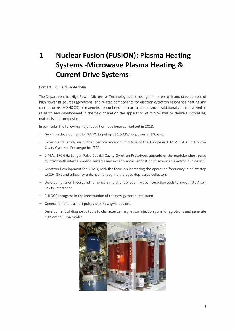
The Department for High Power Microwave Technologies is focusing on the research and development of
high power RF sources (gyrotrons) and related components for electron cyclotron resonance heating and
current drive (ECRH&CD) of magnetically confined nuclear fusion plasmas. Additionally, it is involved in
research and development in the field of and on the application of microwaves to chemical processes,
materials and composites.
In particular the following major activities have been carried out in 2018:
– Gyrotron development for W7-X, targeting at 1.5 MW RF power at 140 GHz.
– Experimental study on further performance optimization of the European 1 MW, 170 GHz Hollow-
Cavity Gyrotron Prototype for ITER.
– 2 MW, 170 GHz Longer Pulse Coaxial-Cavity Gyrotron Prototype, upgrade of the modular short pulse
gyrotron with internal cooling systems and experimental verification of advanced electron gun design.
– Gyrotron Development for DEMO, with the focus on increasing the operation frequency in a first step
to 204 GHz and efficiency enhancement by multi-staged depressed collectors.
– Developments on theory and numerical simulations of beam-wave interaction tools to investigate After-
Cavity-Interaction.
– FULGOR: progress in the construction of the new gyrotron test stand
– Generation of ultrashort pulses with new gyro-devices.
– Development of diagnostic tools to characterize magnetron injection guns for gyrotrons and generate
high order TEmn modes
1 Nuclear Fusion (FUSION): Plasma Heating Systems -Microwave Plasma Heating & Current Drive Systems-
2
1.1 Gyrotron Development for W7-X
Contact: Dr. Konstantinos Avramidis
During the first experimental campaign (OP 1) of the stellarator Wendelstein 7-X (W7-X), the Electron
Cyclotron Resonance Heating (ECRH) system, consisting of ten 1 MW, 140 GHz gyrotrons, performed
remarkably well: the available EC heating and current-drive power in the plasma ranged from 7 to 9 MW,
that is, W7-X is using the world’s largest ECRH installation today. In view of the second experimental
campaign (OP 2) in 2021, even higher ECRH power is desired; hence an upgrade of the ECRH system has
been under consideration for some time. Motivated by this, studies on upgrading the existing 140 GHz,
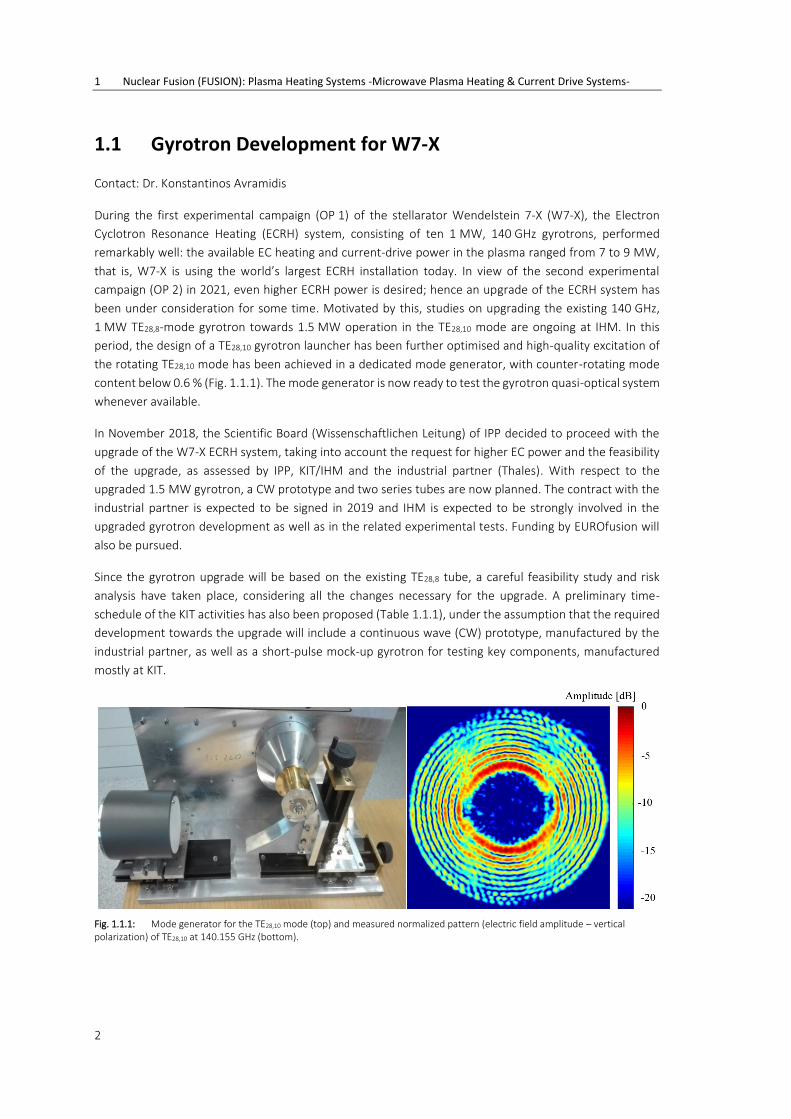
1 MW TE28,8-mode gyrotron towards 1.5 MW operation in the TE28,10 mode are ongoing at IHM. In this
period, the design of a TE28,10 gyrotron launcher has been further optimised and high-quality excitation of
the rotating TE28,10 mode has been achieved in a dedicated mode generator, with counter-rotating mode
content below 0.6 % (Fig. 1.1.1). The mode generator is now ready to test the gyrotron quasi-optical system
whenever available.
In November 2018, the Scientific Board (Wissenschaftlichen Leitung) of IPP decided to proceed with the
upgrade of the W7-X ECRH system, taking into account the request for higher EC power and the feasibility
of the upgrade, as assessed by IPP, KIT/IHM and the industrial partner (Thales). With respect to the
upgraded 1.5 MW gyrotron, a CW prototype and two series tubes are now planned. The contract with the
industrial partner is expected to be signed in 2019 and IHM is expected to be strongly involved in the
upgraded gyrotron development as well as in the related experimental tests. Funding by EUROfusion will
also be pursued.
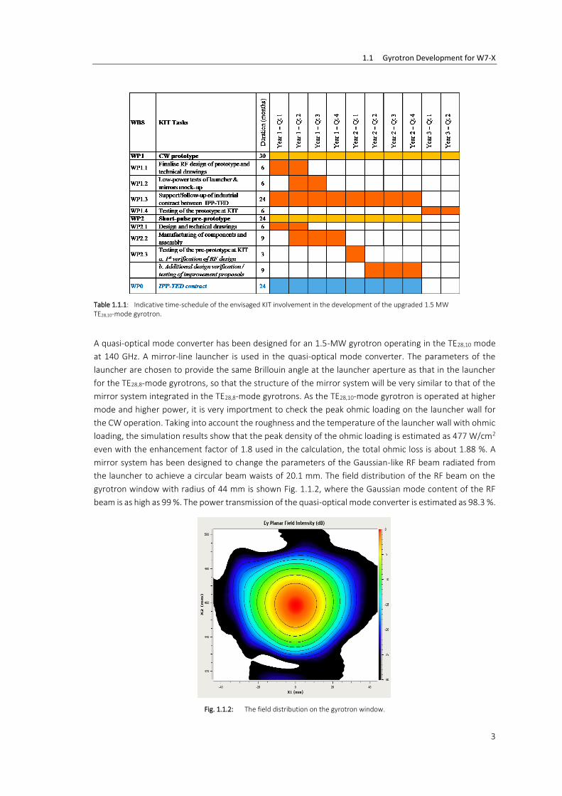
Since the gyrotron upgrade will be based on the existing TE28,8 tube, a careful feasibility study and risk
analysis have taken place, considering all the changes necessary for the upgrade. A preliminary time-
schedule of the KIT activities has also been proposed (Table 1.1.1), under the assumption that the required
development towards the upgrade will include a continuous wave (CW) prototype, manufactured by the
industrial partner, as well as a short-pulse mock-up gyrotron for testing key components, manufactured
mostly at KIT.
Fig. 1.1.1: Mode generator for the TE28,10 mode (top) and measured normalized pattern (electric field amplitude – vertical polarization) of TE28,10 at 140.155 GHz (bottom).
1.1 Gyrotron Development for W7-X
3
Table 1.1.1: Indicative time-schedule of the envisaged KIT involvement in the development of the upgraded 1.5 MW TE28,10-mode gyrotron.
A quasi-optical mode converter has been designed for an 1.5-MW gyrotron operating in the TE28,10 mode
at 140 GHz. A mirror-line launcher is used in the quasi-optical mode converter. The parameters of the
launcher are chosen to provide the same Brillouin angle at the launcher aperture as that in the launcher
for the TE28,8-mode gyrotrons, so that the structure of the mirror system will be very similar to that of the
mirror system integrated in the TE28,8-mode gyrotrons. As the TE28,10-mode gyrotron is operated at higher
mode and higher power, it is very importment to check the peak ohmic loading on the launcher wall for
the CW operation. Taking into account the roughness and the temperature of the launcher wall with ohmic
loading, the simulation results show that the peak density of the ohmic loading is estimated as 477 W/cm2
even with the enhancement factor of 1.8 used in the calculation, the total ohmic loss is about 1.88 %. A
mirror system has been designed to change the parameters of the Gaussian-like RF beam radiated from
the launcher to achieve a circular beam waists of 20.1 mm. The field distribution of the RF beam on the
gyrotron window with radius of 44 mm is shown Fig. 1.1.2, where the Gaussian mode content of the RF
beam is as high as 99 %. The power transmission of the quasi-optical mode converter is estimated as 98.3 %.
Fig. 1.1.2: The field distribution on the gyrotron window.

1 Nuclear Fusion (FUSION): Plasma Heating Systems -Microwave Plasma Heating & Current Drive Systems-
4
1.2 Gyrotron Development for ITER
Contact: Dr. Tomasz Rzesnicki
1.2.1 Experimental study on further performance optimization of the European 1 MW, 170 GHz Hollow-Cavity Gyrotron Prototype.
The IHM team is working on the improvement of the conventional hollow-cavity gyrotron technology. The
short-pulse 1 MW, 170 GHz gyrotron prototype for ITER, designed, fabricated and tested by KIT, presents
very stable gyrotron operation at 170.1 GHz in the nominal cavity mode TE32,9. The RF output power is
above 1 MW with an efficiency slightly above 40 % in single-stage depressed collector operation (SDC).
Further experiments with the 1 MW short pulse gyrotron have shown that the total efficiency of the tube
can be improved by reducing the space-charge voltage depression of the electron beam. This may be
achieved by introducing simple internal structures in the area of the mirror-box or by shifting of the
retarding voltage closer to the collector (i.e. retarding voltage on the outer gyrotron body). Different types
of such structures have been experimentally tested in the SP gyrotron increasing the total efficiency of the
tube. The current goal is to find a solution, which would be compatible with existing CW gyrotron
technology and could be easlily implemented in the next long pluse gyrotron. A suitable structure (Fig.
1.2.1) was proposed and experimentally tested, delivering a 12% increase of the efficiency compared to
the regular gyrotron configuration. The comparision of all ac hieved results are presented in Fig. 1.2.2.
Fig. 1.2.1: Potential elevating structure

1.2 Gyrotron Development for ITER
5
Fig. 1.2.2: RF power and total efficiency vs. retarding voltage obtained experimentally with different gyrotron configurations.
The beam tunnel is a critical part of the gyrotron, where unwanted parasitics oscillation can be excited
having a negatively influence on the gyrotron performace. For this reason, very complicated and expensive
constructions of beam tunnels consisting of ceramic damping structures are being used. Currently, the
motivation is to build a simply-structured metallic alternative, more robust, less expensive and with
comperable or even better dampig features. The first prototype of a fully metallic structure (Fig. 1.2.3) with
an optimized inner wall contur has been tested with very encouraging results. During the tests, in a wide
range of operating points, practically no parasitic signals were observed. Also an almost linear increase of
the output power with respect to the beam current was demonstrated, which was not the case for gyrotron
operation disturbed by the parasitic oscillation. Further tests of metallic beam tunel versions are ongoing.
Fig. 1.2.3: First prototype of fully metallic beam tunnel

1 Nuclear Fusion (FUSION): Plasma Heating Systems -Microwave Plasma Heating & Current Drive Systems-
6
1.3 Gyrotron Development for DEMO
Contact: K. Avramidis
The R&D towards a gyrotron that will meet the requirements posed by the envisaged Electron Cyclotron
Heating and Current Drive system for DEMO is, at the largest part, performed within the Work Package
Heating and Current Drive (WPHCD) of EUROfusion. The studies are in line with the European Fusion
Roadmap towards a demonstration power plant. The current EU DEMO1 baseline poses significant
challenges on the gyrotron. These are the need for dual, high-frequency operation (170/204 GHz) and/or
fast frequency step-tunability, as well as the requirements for higher power (2 MW), higher overall
efficiency ( 60 %), and a higher level of Reliability-Availability-Maintainability-Inspectability (RAMI), in line
with that of a power plant. To keep the gyrotron R&D relevant with respect to possible baseline changes
and to alternative reactor configurations towards a future power plant, efficient MW-class gyrotron
operation at higher (~240 GHz) frequencies is also considered in parallel.
The advanced concept of the coaxial gyrotron has been selected as being the most promising, compared
to the conventional hollow-cavity gyrotron, towards the higher power and frequency target, since the
enhanced mode selectivity of coaxial cavities permits stable operation at very high-order modes, which are
compatible with large dimensions of the gyrotron cavity. The 170 GHz, 2 MW short-pulse coaxial gyrotron
at KIT has already exhibited excellent performance at ms pulses. The next step for coaxial gyrotron
technology towards DEMO is to prove experimentally its capability for long-pulse operation. To this end, a
longer-pulse 170 GHz, 2 MW coaxial cavity gyrotron is currently under development at KIT. This gyrotron is
based on the short-pulse coaxial gyrotron, which was completely re-built, so that that all the key
components i.e. beam tunnel, cavity, and quasi-optical system have independent cooling systems.
The goal of this upgrade is to be able to extend the pulse length up to 100 ms, provided that an axial
sweeping system is used for the collector. For the verification of the manufacturing and the assembly of
the new longer-pulse gyrotron, a short-pulse (ms) test campaign took place, using the old diode Magnetron
Injection electron Gun (MIG) from the short-pulse tube. The verification was fully successful: after the
conditioning phase and optimisation of the gyrotron operation parameters, the nominal cavity mode TE34,19
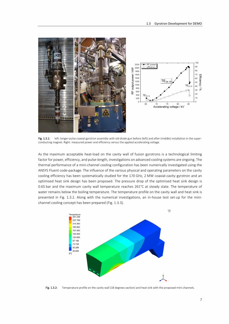
was excited at 169.9 GHz with an output RF power close to 2.1 MW and an efficiency slightly above 30 %
(in non-depressed collector operation). After further optimization of the magnetic field and by slightly
increasing the beam current to 80 A, the RF output power reached nearly 2.2 MW, with an efficiency close
to 33 % (in non-depressed collector operation). Due to known issues of the old electron gun and a relatively
high body current value, the gyrotron was not operated in depressed collector operation. It is worthwhile
to mention that the low-frequency parasitic oscillations (in the MHz range), which were usually observed
in the previous prototypes of the coaxial gyrotrons, were not observed. In addition, high-frequency
(>100 GHz) oscillations, which could be generated in the beam tunnel section, were also not found during
the operation this tube. The tested gyrotron assembly as well as typical experimental results are shown in
Fig. 1.3.1. After this experimental campaign, the old diode MIG was replaced with a new, advanced triode
MIG with coated emitter edges, procured by Thales and compatible with long-pulse operation. Results on
the first validation of this gun are reported in Section 1.4.
1.3 Gyrotron Development for DEMO
7
Fig. 1.3.1: left: longer-pulse coaxial gyrotron assembly with old diode gun before (left) and after (middle) installation in the super-conducting magnet. Right: measured power and efficiency versus the applied accelerating voltage.
As the maximum acceptable heat-load on the cavity wall of fusion gyrotrons is a technological limiting
factor for power, efficiency, and pulse-length, investigations on advanced cooling systems are ongoing. The
thermal performance of a mini-channel cooling configuration has been numerically investigated using the
ANSYS Fluent code-package. The influence of the various physical and operating parameters on the cavity
cooling efficiency has been systematically studied for the 170 GHz, 2 MW coaxial-cavity gyrotron and an
optimised heat sink design has been proposed. The pressure drop of the optimised heat sink design is
0.65 bar and the maximum cavity wall temperature reaches 261°C at steady state. The temperature of
water remains below the boiling temperature. The temperature profile on the cavity wall and heat sink is
presented in Fig. 1.3.2. Along with the numerical investigations, an in-house test set-up for the mini-
channel cooling concept has been prepared (Fig. 1.3.3).
Fig. 1.3.2: Temperature profile on the cavity wall (18 degrees section) and heat sink with the proposed mini-channels.

1 Nuclear Fusion (FUSION): Plasma Heating Systems -Microwave Plasma Heating & Current Drive Systems-
8
Fig. 1.3.3: Test set-up for the performance analysis of the mini-channel cooling concept.
To keep the development path towards the DEMO gyrotron as fast and cost-effective as possible, the
design of a 2 MW, 170/204 GHz coaxial gyrotron is ongoing, using the existing 170 GHz, 2 MW coaxial
gyrotron as a starting point. Operation at ~240 GHz is also under investigation. The chosen operating modes
are TE34,19, TE40,23, and TE48,26 at 170, 204, and 237 GHz, respectively. The modes at frequencies above
200 GHz can only be excited by the use of the new super-conducting 10.5 T magnet under procurement by
TESLA Engineering Ltd (see Section 1.6). Therefore, in this period, the two existing triode coaxial electron
guns, namely the MIG with coated emitter edges procured by Thales and the Inverse MIG (IMIG),
manufactured at KIT, have been simulated using the magnetic field distribution of the new magnet to assess
whether the required beam quality for proper operation can be achieved. The obtained results of the gun
simulations using the in-house code-package ARIADNE, were used for the cavity interaction simulations
performed with the code-package EURIDICE. With respect to dual-frequency 170/204 GHz operation, the
interaction simulations show a generated RF output power of 2.6/2.1 MW and an interaction efficiency of
38.3/34.2 % at 170/204 GHz, respectively. The values are determined in accordance to the gyrotron
development constraints, where the cavity wall loading is limited to 2 kW/cm2. The results are summarised
in Table 1.3.1. A typical start-up scenario is shown in Fig. 1.3.4.
Fig. 1.3.4. Start-up scenario at 8.23 T and I = 68 A using the magnetic field distribution of the upcoming 10.5 T magnet and the IMIG at a nominal beam energy of 86.4 keV.

1.3 Gyrotron Development for DEMO
9
MIG with coated emitter Inverse MIG
Frequency [GHz] 170.00 204.15 170.00 204.15
Mode TE34,19 TE40,23 TE34,19 TE40,23
RF Power [MW] 2.60 2.08 2.57 2.08
Interaction Efficiency [%]
38.3 34.2 38.0 33.8
Beam energy [keV] 91.5 87.5 91.5 87.5
Beam current [A] 75 68 75 68
Magnetic field [T] 6.86 8.23 6.86 8.23
Table 1.3.1: Results of interaction simulations with EURIDICE in the gyrotron cavity and non-linear up-taper, assuming realistic magnetic field profile and electron beam properties obtained by ARIADNE.
A quasi-optical mode converter has been designed for an dual-frequency coaxial-cavity gyrotron, which is
operated in the TE34,19 mode at 170 GHz and the TE40,23 mode at 204 GHz. A mirror-launcher has been
designed for the dual-frequency coaxial-cavity gyrotron. The simulation results show that the Gaussian-
mode contents at the launcher aperture are 97.17% and 96.58% when the launcher operated in the TE34,19
mode at 170 GHz and in the TE40,23 mode at 204 GHz, respectively. The field distributions are shown
in Fig. 1.3.5.
Fig. 1.3.5: Field distribution on the launcher wall (linear scale 0~1): operating in the TE34,19 mode at 170 GHz (left) and in the TE40,23 mode at 204 GHz (right).

1 Nuclear Fusion (FUSION): Plasma Heating Systems -Microwave Plasma Heating & Current Drive Systems-
10
Fig. 1.3.6: A coaxial four stages MDC at (left) and a cylindrical two stages MDC (right).
A mirror system is currently being developed for the dual-frequency gyrotron.
The target of 60 % efficiency for the DEMO gyrotron implies the development of advanced, Multi-Stage
Depressed Collectors (MDC) to increase the energy recuperation from the spent electron beam. The
challenge for the design of a successful MDC system for a high power gyrotron is the sorting of the
magnetically confined electrons of the spent beam on the electrodes, according to their kinetic energy. The
E×B drift is considered as a very promising concept for this purpose, as was proposed by Pagonakis et al. in
2008. A coaxial and a cylindrical design approach (see Fig. 1.3.6) based on the configuration of an azimuthal
electric field using helical electrodes have been extensively investigated. A preliminary conceptual design
of an E×B drift MDC system for gyrotrons is ongoing (Fig. 1.3.7) for the validation of the principle in a short-
pulse, high-frequency, high-power gyrotron. The construction and testing are planned in the near future.

1.3 Gyrotron Development for DEMO
11
Fig. 1.3.7: Drawings of the preliminary conceptual design of a two-stage E×B MDC.
The consideration of frequency step-tunability of the DEMO gyrotron is related to the required option to
fine-tune, by changing the gyrotron frequency, the deposition location of the microwave energy into the
plasma, in order to support plasma instability control. In particular, the Electron Cyclotron (EC) system can
deposit microwave power localised in the space near the intersection of the microwave beam and the
electron cyclotron resonance. Therefore, one important application of EC is to locally drive current at the
modes of MHD instabilities, which are localized near rational magnetic flux surfaces in tokamaks. This
requires a quasi-continuous steering of the absorption (resonance) location over a certain range of flux
surfaces. The steering of the absorption can be achieved by changing the launching angle of the microwave
beam, or by tuning the frequency of the microwaves. The latter is based on the fact that the frequency of
the EC resonance is proportional to the magnetic field. Since there is a gradient of magnetic field in the
tokamak, the position of the EC resonance shifts as the microwave frequency varies, and this is the so-
called frequency steering, as illustrated in Fig. 1.3.8.
The principle of this steering mechanism is not new, but the feasibility of the frequency steering for EU
DEMO has not been extensively studied up to now. A comprehensive investigation has now been initiated
in the frame of a EUROfusion Engineering Grant, which involves the study of the current-drive performance
and the engineering feasibility of frequency steering, with respect to the transmission system, the windows,
and the gyrotrons. The work is being performed in collaboration primarily with CNR, Italy and IPP.
Fig. 1.3.8: Illustration of a first simulation of the localized current drive from the equatorial port of EU DEMO achieved at different frequencies.

1 Nuclear Fusion (FUSION): Plasma Heating Systems -Microwave Plasma Heating & Current Drive Systems-
12
1.4 Advanced electron gun design for gyrotrons
Contact: Dr. Ioannis Pagonakis
An improved magnetron injection gun (MIG) for application in the coaxial cavity gyrotron has been designed
at KIT and manufactured by the industrial partner Thales Electron Devices (TED).
The new MIG has several novelties, such as: (i) the design satisfies the criteria for the suppression of the
electron trapping mechanisms, (ii) a new type of emitter ring is used for the suppression of the influence
of the manufacturing tolerances and misalignments on the quality of the generated electron beam (see Fig.
1.4.1), and (iii) the design was optimized to generate good beam quality in a wide variety of magnetic field
profiles to increase the flexibility.
Fig. 1.4.1: New MIG for coaxial cavity gyrotron with anti-emissive coating of the emitter.
Preliminary experiments were performed with promising results. The triode operation of the gun was
shortly investigated and a power in the range of 2 MW was measured as shown in Fig. 1.4.2.
Fig. 1.4.2: Experimental measured output power P and theoretical pitch factor as functions of the modulation anode potential.

1.5 Developments on theory and numerical simulations
13
1.5 Developments on theory and numerical simulations
Contact: Dr. Stefan Illy
The simulation model of gyrotron interaction has been extended to investigate the possibility of parasitic
After-Cavity Interaction (ACI) in the gyrotron launcher. In contrast to previous works, the extended
simulation model allows, for the first time, to consider a very large interaction region (i.e. cavity, uptaper,
and launcher) using accurate electromagnetic field representation not only in the cavity and uptaper, but
also in the launcher. In particular, the code-package EURIDICE for gyrotron interaction simulations and
cavity design has been upgraded to address also the coupled TE modes which form the electromagnetic
field in the launcher. An interface has been developed, in order to import to EURIDICE the launcher
electromagnetic field as obtained by the code KarLESSS. Using the newly developed model, the 1 MW,
140 GHz gyrotron for W7-X, the 1 MW, 170 GHz European gyrotron for ITER, and the 170 GHz, 2 MW
coaxial-cavity gyrotron at KIT, have been studied. As it turned out, parasitic ACI in the launcher is possible
in several cases, resulting in a reduction of gyrotron efficiency. An example of such a case is given in
Fig. 1.5.1. The extended model provides additional means to possibly remove previously observed
discrepancies between gyrotron simulations and experimental results.
Fig. 1.5.1: Example of ACI in the launcher that can occur in the 140 GHz, 1 MW gyrotron for W7-X. Cavity and uptaper extend up to 85 mm (purple region); launcher up to 245 mm (red region). Black line shows total RF power versus the gyrotron axis; coloured lines show power of individual modes, as the operating TE28,8 mode is converted in the launcher to a mixture of 9 modes, in order to achieve a Gaussian RF field profile. A reduction of ~100 kW due to ACI in the launcher is visible in the total RF power.

1 Nuclear Fusion (FUSION): Plasma Heating Systems -Microwave Plasma Heating & Current Drive Systems-
14
1.6 FULGOR (Fusion Long-Pulse Gyrotron Laboratory)
Contact: Dr. Gerd Gantenbein
The existing gyrotron test facility at KIT, which had been designed and built about 30 years ago, plays a
worldwide leading role in the development of high-power gyrotrons for nuclear fusion applications. This
facility offered the unique opportunity to develop and test the first CW high power series gyrotrons for the
stellarator W7-X in collaboration with IPP and Thales Electron Devices as the industrial partner.
The target parameters of the new gyrotron test facility are well beyond the capabilities of the existing one.
The new teststand will strongly support KIT’s leading role in the development of advanced gyrotrons. It will
help to answer the questions regarding the technical limits and new physical designs for future high-power
microwave tubes. The key parameters of FULGOR will be:
Full CW operation with up to 10 MW electrical power (, corresponding to
>= 4 MW RF power (assuming an efficiency of the gyrotron >= 40%)
Support of advanced energy recovery concepts, e.g. multi-stage depressed collector (MSDC)
The high voltage power supply (HVPS) will support an operating voltage of up to 130 kV with up to 120 A
beam current in short pulse operation and 90 kV / 120 A in continues wave regime. A superconducting
magnet which allows operation of gyrotrons at frequencies well above 200 GHz will be a major component
of FULGOR. Other significant components of the teststand are: cooling system, control electronics and
interlock system, RF diagnostics including high-power RF absorber loads.
The capabilities of FULGOR will enable the development and CW tests of gyrotrons for future fusion
machines like ITER and DEMO. Fig. 1.6.1 is a simplified CAD view of the complete FULGOR system.
Substantial progress has been achieved in the planning, procurement and installation of major systems of
the new teststand.
High Voltage Power Supply (HVPS): In 2018 the final acceptance tests of the CW power supply and the
pulsed PS has been performed. The procurement of components and the production of the body power
supply has been started and is ongoing.
Superconducting magnet: This is a very challenging component since the requirements are beyond what is
industrial standard. In particular, a large borehole diameter (261 mm) in combination with a high magnetic
field requirement (up to 10.5 T to ensure RF radiation up to 240 GHz) calls for a very clever design of the
magnet. In 2018 the procurement has been placed at TESLA company, GB, manufacturing of major parts
has started and the delivery of the magnet to KIT is expected in summer 2019.

1.6 FULGOR (Fusion Long-Pulse Gyrotron Laboratory)
15
Fig. 1.6.1: CAD view of FULGOR teststand and installation of CW modules.

1 Nuclear Fusion (FUSION): Plasma Heating Systems -Microwave Plasma Heating & Current Drive Systems-
16
1.7 Generation of ultrashort pulses with new gyro-devices
Contact: M.Sc. Alexander Marek
In this project, we study the generation of a periodic sequence of powerful short pulses. The need for
powerful pulsed sources of millimeter and sub-millimeter (sub-THz) radiation is motivated by a large
number of fundamental problems and practical applications, as diagnostics of plasma, photochemistry,
biophysics, new locating systems, and the spectroscopy of various media.
The pulses will be formed by a feedback loop of an amplifier and a nonlinear absorber. For prove of concept,
such a feedback loop should be first realized at a frequency of 34 GHz, but the final applications of the
generated pulses will be in the sub-THz frequency range. Therefore, the key elements for a helically
corrugated gyro-TWT with the frequency of 260 GHz, as well as a non-linear cyclotron absorber appropriate
for this frequency range will be developed in parallel to the design of a feedback-loop at 34 GHz. In the
34 GHz system, a gyrotron-traveling-wave-tube with helical corrugated interaction-region (helical gyro-
TWT) will be used as amplifier device, while a rectilinear electron beam in a cylindrical interaction space
will be used as cyclotron absorber. In the final 260 GHz generator, an absorber based on a helical gyro-TWT
operating in the Kompfner-Dip regime should be used as absorber device. The Kompfner-Dip absorber has
the advantage of a halved magnetic field compared to the cylindrical absorber (10 T → 5 T). The amplifier
(helical gyro-TWT) will run in a regime optimal for the maximal amplification of ultra-short pulses, while the
absorber will run in a regime, where low-energy pulses are absorbed and powerful pulses can pass the
absorber without loss of energy.
“Cold” simulations of the helical interaction region and of additional components as mirror systems for
input/output systems were performed in a first step of the project [Ma17, Ma18]. For this, our in-house
developed full-wave simulation tool KarLESSS was used. Currently, “hot” simulations of the interaction are
performed. Simulations of the separated amplifier and absorber components at 34 GHz are performed with
the commercial tool CST [Gi17]. In parallel, we investigate in the usage of the advanced simulation program
“PICLas”, developed by the Institute of Aerodynamics and Gas Dynamics at the University of Stuttgart.
PICLas provides the great opportunity to verify the CST simulations and to allow a full PIC simulation of a
coupled amplifier-absorber system.
For the amplifier as well as the absorber devices of a final 260 GHz pulsed generator, a broad-band CUSP-
type electron gun was designed (see Fig. 1.7.1). The gun allows the generation of high quality small-orbit
electron beams, as required for helical gyro-TWTs. The designed gun can be used for helical gyro-TWTs
operating at various frequencies, from the W-band up to the J-band. For the development of the gun the
in-house tools Ariadne and ESRAY were used. In addition, for the first time a cross-check and investigation
of unwanted mode-excitation were performed with the commercial software CST-MICROWAVE-STUDIO.

1.8 Gyrotron Diagnostics
17
Fig. 1.7.1: CUSP-type electron gun with beam tunnel, to be attached to a helical gyro-TWT (top). Cross-section of a helical waveguide structure for a helical gyro-TWT (bottom).
Collaboration: In Collaboration with the Institute of Applied Physics, Russian Academy of Sciences (IAP- RAS)
and with support of the Institute of Aerodynamics and Gas Dynamics, University of Stuttgart.
Funding: The research is supported by the joint RSF-DFG project (Je 711/1-1) Generation of Ultrashort
Pulses in Millimeter and Submillimeter Bands for Spectroscopy and Diagnostic of Various Media Based on
Passive Mode-locking in Electronic Devices with Nonlinear Cyclotron Absorber in the Feedback Loop.
1.8 Gyrotron Diagnostics
1.8.1 A diagnostic device for the study of Magnetron Injection Guns used in high-power, high-frequency gyrotrons.
Contact: Dr. Zisis Ioannidis
The quality of the electron beam generated by a Magnetron Injection Gun (MIG) is very important for the
performance of high-power, high-frequency gyrotrons. In practice, several parameters such as mechanical
misalignments during assembly, manufacturing tolerances, temperature inhomogeneity and emitter
roughness, significantly affect the expected performance of the MIG. For this reason, it is important to be
able to measure the electron properties. During gyrotron operation, that kind of measurement is practically
impossible. A more reasonable approach is to develop a diagnostic device based on the retarding field
method, where the MIG can be connected and studied prior the gyrotron operation.
Fig. 1.8.1 presents the prototype device that was manufactured at KIT after detailed simulation studies.
The operating principle of the diagnostic device is quite simple. The device is installed in the
superconducting magnet that is used for the gyrotron operation. The generated electron beam of the MIG
under study is accelerated by the anode-cathode potential difference and is guided towards the position
where the gyrotron interaction region would be by a focusing magnetic field. A diaphragm with a small
opening is intercepting the electron beam, allowing only to a specific azimuthal sample of the beam to pass
through and enter the retarding field that is created between the diaphragm and the reflector. Depending
on the applied retarding potential and the parallel energy of the electrons, some electrons are reflected
backwards, whereas those that have enough parallel energy to overcome the retarding forces of the
reflector are finally collected by the collector.

1 Nuclear Fusion (FUSION): Plasma Heating Systems -Microwave Plasma Heating & Current Drive Systems-
18
Fig. 1.8.1: Representation of the prototype diagnostic device that was manufactured for the study of the beam quality of magnetron injection guns.
Various useful measurements can be made with such a device. First, it is possible to measure the azimuthal
homogeneity of the emission by grounding the reflector, rotating the diaphragm and measuring the
collector current with respect to the azimuthal position of the diaphragm’s slot. Second, for a specific
position of the diaphragm, it is straightforward to measure the parallel energy distribution of the electrons
by varying the reflector potential and measuring the collector current. Then, it is also possible to estimate
the complete pitch factor distribution of the electrons. Finally, by changing the magnetic field profile and
measuring the collector current it is possible to estimate the beam thickness. Experiments with MIGs that
have been operated in the past with the 2 MW, 170 GHz short-pulse prototype gyrotron are currently
ongoing. Further tests with other MIGs are planned for the future.
1.8.2 Experimental study on further performance optimization of the European 1 MW, 170 GHz Hollow-Cavity Gyrotron Prototype.
Contact: M.Sc. Tobias Ruess
The quasi-optical mode converter is one key element in the gyrotron design, which consists of the launcher
and three mirrors. Those components convert the high-order rotating waveguide mode, excited in the
interaction cavity, into the linearly polarized fundamental Gaussian beam (TEM00 mode). In order to
perform a proper verification of the quasi-optical system a low power (~ 1 mW – cold test) measurement
of this converter system is vital before final installation into the high power fusion gyrotron. The first step
of validation of the quasi-optical mode converter is the excitation of the correct high-order TEm,n-mode
with a mode generator. In the past, this mode generator was adjusted manually which was a very time

1.8 Gyrotron Diagnostics
19
consuming task because of the high spectral density of the mode spectrum in oversized waveguides, as
well as the large number of degrees of freedom of the mode generator setup. To imprive this procedure
two high-precision linear drivers (horizontal and vertical movement) are installed. Using this electronical
adjustable components, the mode generator setup was automated. Mode evaluation algorithms have been
implemented to determine the mode indices and the mode purity. The mode generator setup is shown in
Fig. 1.8.2. The mode generator is operated with a VNA (Vector Network Analyzer), covering a frequency
range from 140-330 GHz using extension modules and a rectangular standard waveguide pick-up receiving
antenna. This antenna is mounted on a 3D measurement arm, where a stepwise 2D scan of the plane
parallel to the output of the mode generator can be taken. The amplitude pattern of the TE28,8-mode
operating at 140.006 GHz is depicted in Fig. 1.8.3. The scalar mode content is calculated to 94.5 % with a
extremly low counter-rotating amount of around 0.33 %. The complete quasi-optical system (launcher and
mirrors) are tested after the successful excitation of the mode. This measuremt delivers a scalar/vectorial
Gaussian mode contet of 98.3/97.5 %.
With these improvements the precision of the measurement has been increased and the measurement
time has been decreased substantially.
Fig. 1.8.2: Photo of the the automated mode generator setup.
Fig. 1.8.3: Measured amplitude pattern of the TE28,8 mode operating at 140.006 GHz with a pixel size of 0.2x0.2 mm.

1 Nuclear Fusion (FUSION): Plasma Heating Systems -Microwave Plasma Heating & Current Drive Systems-
20
Involved Staff:
KIT/IHM: K. Avramidis, B. Ell, Dr. G. Gantenbein, Dr. S. Illy, Dr. Z. Ioannidis, Prof. J. Jelonnek, Dr. J. Jin, Dr. P.
Kalaria, Th. Kobarg, R. Lang, W. Leonhardt, A. Marek, M. Marschall, D. Mellein, Meier (KIT, IAM-AWP), Dr.
I. Pagonakis, A. Papenfuß, S. Ruess (KIT CS), T. Ruess, Dr. T. Rzesnicki, Prof. Dr. Theo A. Scherer (KIT, IAM-
AWP), M. Schmid, Dr. D. Strauss (KIT, IAW-AWP), Prof. M. Thumm, S. Wadle, J. Weggen, Dr. Ch. Wu, A. Zein,
IGVP (University of Stuttgart): Dr. W. Kasparek, Dr. C. Lechte, Dr. B. Plaum, F. Remppel, H. Röhlinger, B. Roth,
S. Wolf, A. Zeitler, IPP (Greifswald/Garching): B. Berndt, Dr. H. Braune, F. Hollmann, L. Jonitz, Dr. H. Laqua,
Dr. S. Marsen, F. Noke, M. Preynas, F. Purps, A. Reintrog, T. Schulz, T. Stange, P. Uhren, M. Weißgerber, F.
Wilde
Journal Publications
W7-X Team; Dinklage, A.; Beidler, C. D.; Helander, P.; Fuchert, G.; Maaßberg, H.; Rahbarnia, K.; Sunn
Pedersen, T.; Turkin, Y.; Wolf, R. C.; Alonso, A.; Andreeva, T.; Blackwell, B.; Bozhenkov, S.; Buttenschön, B.;
Czarnecka, A.; Effenberg, F.; Feng, Y.; Geiger, J.; Hirsch, M.; Höfel, U.; Jakubowski, M.; Klinger, T.; Knauer,
J.; Kocsis, G.; Krämer-Flecken, A.; Kubkowska, M.; Langenberg, A.; Laqua, H. P.; Marushchenko, N.; Mollén,
A.; Neuner, U.; Niemann, H.; Pasch, E.; Pablant, N.; Rudischhauser, L.; Smith, H. M.; Schmitz, O.; Stange, T.;
Szepesi, T.; Weir, G.; Windisch, T.; Wurden, G. A.; Zhang, D.; Baumann, K.; Dammertz, G.; Fietz, W. H.;
Gantenbein, G.; Huber, M.; Hunger, H.; Illy, S.; Jelonnek, J.; Kobarg, T.; Lang, R.; Leonhardt, W.; Losert, M.;
Meier, A.; Mellein, D.; Papenfuß, D.; Samartsev, A.; Scherer, T.; Schlaich, A.; Spiess, W.; Thumm, M.; Wadle,
S. (2018). Magnetic configuration effects on the Wendelstein 7-X stellarator. Nature physics, 14 (10), 1067.
W7-X Team; Dinklage, A.; Beidler, C. D.; Helander, P.; Fuchert, G.; Maaßberg, H.; Rahbarnia, K.; Sunn
Pedersen, T.; Turkin, Y.; Wolf, R. C.; Alonso, A.; Andreeva, T.; Blackwell, B.; Bozhenkov, S.; Buttenschön, B.;
Czarnecka, A.; Effenberg, F.; Feng, Y.; Geiger, J.; Hirsch, M.; Höfel, U.; Jakubowski, M.; Klinger, T.; Knauer,
J.; Kocsis, G.; Krämer-Flecken, A.; Kubkowska, M.; Langenberg, A.; Laqua, H. P.; Marushchenko, N.; Mollén,
A.; Neuner, U.; Niemann, H.; Pasch, E.; Pablant, N.; Rudischhauser, L.; Smith, H. M.; Schmitz, O.; Stange, T.;
Szepesi, T.; Weir, G.; Windisch, T.; Wurden, G. A.; Zhang, D.; Baumann, K.; Dammertz, G.; Fietz, W. H.;
Gantenbein, G.; Huber, M.; Hunger, H.; Illy, S.; Jelonnek, J.; Kobarg, T.; Lang, R.; Leonhardt, W.; Losert, M.;
Meier, A.; Mellein, D.; Papenfuß, D.; Samartsev, A.; Scherer, T.; Schlaich, A.; Spiess, W.; Thumm, M.; Wadle,
S. (2018). Publisher Correction: Magnetic configuration effects on the Wendelstein 7-X stellarator. Nature
physics, 14 (8), 867.
W7-X Team; Dinklage, A.; Beidler, C. D.; Helander, P.; Fuchert, G.; Maaßberg, H.; Rahbarnia, K.; Sunn
Pedersen, T.; Turkin, Y.; Wolf, R. C.; Alonso, A.; Andreeva, T.; Blackwell, B.; Bozhenkov, S.; Buttenschön, B.;
Czarnecka, A.; Effenberg, F.; Feng, Y.; Geiger, J.; Hirsch, M.; Höfel, U.; Jakubowski, M.; Klinger, T.; Knauer,
J.; Kocsis, G.; Krämer-Flecken, A.; Kubkowska, M.; Langenberg, A.; Laqua, H. P.; Marushchenko, N.; Mollén,
A.; Neuner, U.; Niemann, H.; Pasch, E.; Pablant, N.; Rudischhauser, L.; Smith, H. M.; Schmitz, O.; Stange, T.;
Szepesi, T.; Weir, G.; Windisch, T.; Wurden, G. A.; Zhang, D.; Baumann, K.; Dammertz, G.; Fietz, W. H.;
Gantenbein, G.; Huber, M.; Hunger, H.; Illy, S.; Jelonnek, J.; Kobarg, T.; Lang, R.; Leonhardt, W.; Losert, M.;
Meier, A.; Mellein, D.; Papenfuß, D.; Samartsev, A.; Scherer, T.; Schlaich, A.; Spiess, W.; Thumm, M.; Wadle,
S.; Weggen, J. (2018). Magnetic configuration effects on the Wendelstein 7-X stellarator. Nature physics,
14 (8), 855–860.

1.8 Gyrotron Diagnostics
21
Ruess, T.; Avramidis, K. A.; Fuchs, M.; Gantenbein, G.; Illy, S.; Lutz, F.-C.; Marek, A.; Ruess, S.; Rzesnicki, T.;
Thumm, M.; Wagner, D.; Weggen, J.; Jelonnek, J. (2018). Towards Fully Automated Systems for the
Generation of Very High Order Modes in Oversized Waveguides. (A. A. Silaev, Hrsg.)The European physical
journal / Web of Conferences, 195, Art. Nr.: 01030.
Jao, R.-F.; Lin, M.-C. (2018). Efficient and quantitative analysis of photon density of states for two-
dimensional photonic crystals with omnidirectional light propagation. Physical review / E, 98 (5), Art. Nr.:
053306.
Girka, I. O.; Kondratenko, V. M.; Thumm, M. (2018). Higher radial modes of azimuthal surface waves in
magnetoactive cylindrical plasma waveguides. Journal of plasma physics, 84 (6), Art. Nr.: 905840603.
Ginzburg, N. S.; Denisov, G. G.; Vilkov, M. N.; Zotova, I. V.; Sergeev, A. S.; Samsonov, S. V.; Marek, A.;
Jelonnek, J. (2018). PIC Simulations of Ka-band Ultra-Short Pulse Oscillator with Resonance Cyclotron
Absorber in the Feedback Loop. The European physical journal / Web of Conferences, 187, 01021/1–2.
Garavaglia, S.; Aiello, G.; Alberti, S.; Avramidis, K.; Bruschi, A.; Chelis, I. G.; Franck, J.; Gantenbein, G.;
Granucci, G.; Grossetti, G.; Hizanidis, K.; Illy, S.; Jelonnek, J.; Kalaria, P.; Latsas, G.; Moro, A.; Pagonakis, I.;
Peponis, D. V.; Poli, E.; Rispoli, N.; Ruess, S.; Rzesnicki, T.; Scherer, T.; Strauss, D.; Thumm, M.; Tigelis, I.;
Tsironis, C.; Wu, C.; Franke, T.; Tran, M. Q. (2018). EU DEMO EC system preliminary conceptual design.
Fusion engineering and design. 136, 1173-1177.
Abe, D. K.; Whaley, D. R.; Feng, J.; Jelonnek, J.; Kumar, L. (2018). Guest Editorial Special Issue on Vacuum
Electronics. IEEE transactions on electron devices, 65 (6), 2058–2060.
Idehara, T.; Ogawa, I.; Wagner, D.; Thumm, M.; Kosuga, K.; Sabchevski, S. P. (2018). High Purity Mode CW
Gyrotron Covering the Subterahertz to Terahertz Range Using a 20 T Superconducting Magnet. IEEE
transactions on electron devices, 1–6, 65 (7), 3486-3491.
Girka, I. O.; Pavlenko, I. V.; Thumm, M. (2018). Excitation of higher radial modes of azimuthal surface waves
in the electron cyclotron frequency range by rotating relativistic flow of electrons in cylindrical waveguides
partially filled by plasmas. Physics of plasmas, 25 (5), 052109.
Wu, C.; Pagonakis, I. G.; Avramidis, K. A.; Gantenbein, G.; Illy, S.; Thumm, M.; Jelonnek, J. (2018). Gyrotron
multistage depressed collector based on e × B drift concept using azimuthal electric field. I. Basic design.
Physics of plasmas, 25 (3), Art. Nr.: 033108.
Girka, I. O.; Pavlenko, I. V.; Thumm, M. K. A. (2018). Two mechanisms of resonance overlapping in excitation
of azimuthal surface waves by rotating relativistic electron beams. Physics of plasmas, 25 (5), 052111.
Ginzburg, N. S.; Denisov, G. G.; Vilkov, M. N.; Zotova, I. V.; Sergeev, A. S.; Rozental, R. M.; Samsonov, S. V.;
Mishakin, S. V.; Marek, A.; Jelonnek, J. (2018). Ultrawideband Millimeter-Wave Oscillators Based on Two
Coupled Gyro-TWTs With Helical Waveguide. IEEE transactions on electron devices, 65 (6), 2334–2339.
Lin, M.-C.; Illy, S.; Avramidis, K. A.; Thumm, M.; Jelonnek, J. (2018). Study on After Cavity Interaction in a
140-GHz Model TE0.3 Gyrotron Using 3-D CFDTD PIC Simulation. IEEE transactions on plasma science, 46
(6), 1937–1942.
1 Nuclear Fusion (FUSION): Plasma Heating Systems -Microwave Plasma Heating & Current Drive Systems-
22
Chelis, I. G.; Avramidis, K. A.; Ioannidis, Z. C.; Tigelis, I. G. (2018). Improved Suppression of Parasitic
Oscillations in Gyrotron Beam Tunnels by Proper Selection of the Lossy Ceramic Material. IEEE transactions
on electron devices, 65 (6), 2301–2307.
Pagonakis, I. G.; Illy, S.; Ioannidis, Z. C.; Rzesnicki, T.; Avramidis, K. A.; Gantenbein, G.; Kobarg, T.; Piosczyk,
B.; Thumm, M.; Jelonnek, J. (2018). Numerical Investigation on Spent Beam Deceleration Schemes for
Depressed Collector of a High-Power Gyrotron. IEEE transactions on electron devices, 65 (6), 2321–2326.
Franke, T.; Agostinetti, P.; Aiello, G.; Avramidis, K.; Bachmann, C.; Bruschi, A.; Federici, G.; Garavaglia, S.;
Granucci, G.; Grossetti, G.; Jelonnek, J.; Noterdaeme, J.-M.; Simonin, A.; Scherer, T.; Sonato, P.; Strauss, D.;
Tran, M. Q.; Valentine, A.; Vincenzi, P.; Wenninger, R.; Zheng, S. (2018). Review of the Innovative H&CD
Designs and the Impact of Their Configurations on the Performance of the EU DEMO Fusion Power Plant
Reactor. IEEE transactions on plasma science, 46 (5), 1633–1640.
Petelin, M.; Thumm, M. (2018). On the Evolution of Approaches to the Space-Time Symmetry. Natural
science, 10 (03), 81–84.
Avramidis, K. A.; Bertinetti, A.; Albajar, F.; Cau, F.; Cismondi, F.; Gantenbein, G.; Illy, S.; Ioannidis, Z. C.;
Jelonnek, J.; Legrand, F.; Pagonakis, I. G.; Rozier, Y.; Rzesnicki, T.; Savoldi, L.; Thumm, M.; Zanino, R. (2018).
Numerical Studies on the Influence of Cavity Thermal Expansion on the Performance of a High-Power
Gyrotron. IEEE transactions on electron devices, 65 (6), 2308–2315.
Ioannidis, Z. C.; Pagonakis, I. G.; Avramidis, K. A.; Illy, S.; Rzesnicki, T.; Tigelis, I. G.; Gantenbein, G.; Jelonnek,
J. (2018). An Improved Diagnostic Device for Magnetron Injection Guns of High-Power Gyrotrons. IEEE
transactions on electron devices, 65 (6), 2294–2300.
23
2 Renewable Energy (RE): Bioenergy-Feedstocks and Pretreatment-
Contact: Prof. Dr. Georg Müller
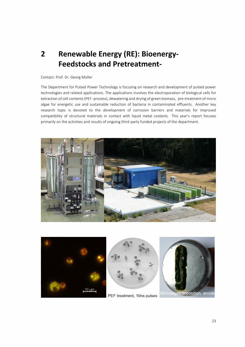
The Department for Pulsed Power Technology is focusing on research and development of pulsed power
technologies and related applications. The applications involves the electroporation of biological cells for
extraction of cell contents (PEF- process), dewatering and drying of green biomass, pre-treatment of micro
algae for energetic use and sustainable reduction of bacteria in contaminated effluents. Another key
research topic is devoted to the development of corrosion barriers and materials for improved
compatibility of structural materials in contact with liquid metal coolants. This year's report focuses
primarily on the activities and results of ongoing third-party funded projects of the department.

2 Renewable Energy (RE): Bioenergy-Feedstocks and Pretreatment-
24
2.1 PEF-Processing of Microalgae and Industrial Water Streams
Contact: Wolfgang Frey
2.1.1 DiWal
Legal restrictions on solvent and bactericide admixture to water-based paint systems in electrocoating lines
for car bodies improve environmental sustainability of these large scale industrial processes, but also favour
growing conditions for unwanted bacterial populations. Bacterial inactivation by PEF treatment is being
tested for feasibility in this project.
First condition for a successful application of PEF-technique for bacterial decontamination of water-based
paint media is that dip coat paint will not be deposited at the electrodes’ surface in the PEF treatment
chamber, which finally would result in blocking of the treatment chamber. Pilot experiments revealed that
paint deposition can be inhibited by utilization of short pulses with a duration between 0.75 µs and 2°µs.
Longer pulses were found to cause paint coagulation and paint deposition at the electrodes.
In collaboration with the Institue of Functional Interfaces, Burkholderia, Sphingomonas and Microbacterium
were identified as main contaminants in electrocoating lines. Inactivation efficiency was tested on isolated
strains for inactivation efficiency of PEF-treatment with 1 µs and 2 µs long pulses.
It can be ascertained that inactivation is highest, when a treatment energy of 80 kJ/l was applied. Reduction
of the treatment energy to 40 kJ/l reduces inactivation rate by 0.5 log on average. Inactivation performance
does not primarily depend on pulse duration. In all cases, bacterial inactivation rate exceeded the required
value of 2 log, Fig. 2.1.1, dashed line. Both results, sufficient inactivation performance at low energy input
and paint-deposition-free operation of PEF-treatment chambers are important prerequisites for successful
implementation of the PEF-technology in electrocoating lines.
Fig. 2.1.1: Inactivation of bacteria isolated from electrocoating lines by PEF-treatment with 1 µs and 2 µs long pulses at a specific treatment energy of 40 kJ/l and 80 kJ/l.
Collaboration: Eisenmann SE, Hochschule Pforzheim, BMW Group, PPG, FreiLacke
Funding: Federal Ministry of Education and Research – BMBF, Grant No. 02WAV1405A
2.1 PEF-Processing of Microalgae and Industrial Water Streams
25
2.1.2 SABANA
Efficient product recovery from microalgae is impeded by the organisms’ robust cell walls. Thus, extraction
of intracellular components from microalgae requires a pretreatment step for cell disruption. A major task
in the H2020 SABANA project is to identify an economic downstream processing pathway, involving
appropriate cell disruption techniques, for the production of amino acid concentrates utilized as fertilizer
in agriculture and horticulture. A first screening of various pretreatment methods for cell disruption, i.e.
enzymatic cell wall digestion, ultrasound application, thermal pretreatment, ball milling, etc. revealed that
PEF-processing and high pressure homogenization (HPH) are the most economic candidates. Both methods
provide high product yields at low energy expenses of 1 MJ/kgdw and less.
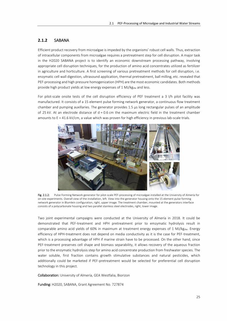
For pilot-scale onsite tests of the cell disruption efficiency of PEF treatment a 3 l/h pilot facility was
manufactured. It consists of a 15 element pulse forming network generator, a continuous flow treatment
chamber and pumping auxillaries. The generator provides 1.5 µs long rectangular pulses of an amplitude
of 25 kV. At an electrode distance of d = 0.6 cm the maximum electric field in the treatment chamber
amounts to E = 41.6 kV/cm, a value which was proven for high efficiency in previous lab-scale trials.
Fig. 2.1.2: Pulse Forming Network generator for pilot-scale PEF-processing of microalgae installed at the University of Almería for on-site experiments. Overall view of the installation, left. View into the generator housing onto the 15 element pulse forming network generator in Blumlein configuration, right, upper image. The treatment chamber, mounted at the generators interface consists of a polycarbonate housing and two parallel stainless steel electrodes, right, lower image.
Two joint experimental campaigns were conducted at the University of Almería in 2018. It could be
demonstrated that PEF-treatment and HPH pretreatment prior to emzymatic hydrolysis result in
comparable amino acid yields of 60% in maximum at treatment energy expenses of 1 MJ/kgdw. Energy
efficiency of HPH-treatment does not depend on media conductivity as it is the case for PEF-treatment,
which is a processing advantage of HPH if marine strain have to be processed. On the other hand, since
PEF-treatment preserves cell shape and biomass separability, it allows recovery of the aqueous fraction
prior to the enzymatic hydrolysis step for amino acid concentrate production from freshwater species. The
water soluble, first fraction contains growth stimulative substances and natural pesticides, which
additionally could be marketed if PEF-pretreatment would be selected for preferential cell disruption
technology in this project.
Collaboration: University of Almería, GEA Westfalia, Biorizon
Funding: H2020, SABANA, Grant Agreement No. 727874

2 Renewable Energy (RE): Bioenergy-Feedstocks and Pretreatment-
26
2.2 Components and electroporation processes
Contact: Martin Sack
2.2.1 ZIM-Wine
In the frame of the joint research project “PEF-treatment of crushed grapes (Elektroporation von
Traubenmaische)” a device for the treatment of crushed grapes by pulsed electric fields (PEF) with a flow
rate of 10t/h is currently being developed in collaboration with the industrial partners ARMBRUSTER
Keltereitechnologie and KEA-TEC. The project is supported by the Federal Ministry for Economic Affairs and
Energy on the basis of a decision by the German Bundestag.
The pulse circuit of the device comprises two Marx generators, which are operated in triggered mode. If
the generators’ charging voltage reaches a predefined level, a trigger signal is generated causing immediate
triggering of both generators. Thereby, triggering is performed by applying an over-voltage to the first spark
gap of each generator. Hence, an additional trigger electrode has been omitted. The triggered operation
enables charging of both generators from a single high-voltage power supply.
Fig. 2.2.1 shows the well synchronized pulse currents of both generators after triggering.
Fig. 2.2.1: Measured pulse currents of both generators.
Collaboration: ARMBRUSTER Keltereitechnologie, KEA-TEC
Funding: The project is supported by the Federal Ministry for Economic Affairs and Energy on the basis of
a decision by the German Bundestag.

2.2 Components and electroporation processes
27
2.2.2 Marx-type Pulse Generator for Stepwise Arbitrary Waveform Generation
A 149-stage pulse generator for stepwise arbitrary waveform generation to drive the Pulsed Electron Beam
Device (GESA) has been set up and is currently being tested. Fig. 2.2.2 shows photos of the generator. The
generator has been designed for an output voltage of 120 kV and a load current of up to 600 A. The
generator features a helical stage arrangement with a quasi-coaxial current return path. Each stage
comprises a capacitor and an IGBT switch together with a bypass diode. A microcontroller at each stage
enables individual toggling of each stage switch, synchronized to a trigger event common for all stages.
During pulse generation the stage capacitors of active stages are continuously discharged causing a droop
of the output voltage. Stepwise arbitrary waveform generation allows for an active droop compensation.
Thereby, an additional stage is activated as soon as the output voltage drops by an amount equal to the
stage voltage. Fig. 2.2.3shows the output voltage of the generator with active droop compensation in red
in comparison to the the decreasing voltage shape without droop compensation (black).
Fig. 2.2.2: 9-stage pulse generator for arbitrary waveform generation without current return path (left) and with attached current return path (right).
Fig. 2.2.3: Output voltage of the generator with droop compensation (red) in comparison to a pulse shape without droop compensation (black).

2 Renewable Energy (RE): Bioenergy-Feedstocks and Pretreatment-
28
2.3 Concentrating solar power (CSP)/ Liquid metal
– Material research – improving the compatibility of materials for CSP
Contact: Dr. Alfons Weisenburger
Liquid metals as advanced heat-transfer media (HTM) and storage media for CSP are a promising research
area that will result in performance and efficiency increase and reduced costs. Within LIMCKA (Liquid Metal
Competence Center KArlsruhe) several institutes and laboratories of the KIT combine their long-standing
experience and specific expertise in material research, system engineering, safety and thermal-hydraulics
to tackle all relevant aspects of liquid metals as HTM. The IHM focus on compatibility research by surface
optimization of existing materials using GESA and development of new materials that are able to form
protective alumina scales. Besides liquid metal, efforts to explore the compatibility of the developed
materials with other relevant advanced heat transfer media like solar salts were done in cooperation with
colleagues from DLR.
Some of the tasks are embedded in European projects and cooperations like with DLR and EERA-CSP.
2.3.1 GESA – SOFIE
Separating the emitting plasma by a dedicated grid from the accelerating space allowed to control
important parameters like emission current density and plasma production more independently. This
results in several improvements of such new cathodes like improved angle distribution of the electrons, a
better control of the emission area and stable emission currents above 0.4 A/cm2.
Laser-induced fluorescence-dip diagnostic to investigate in detail the electric field distribution was set-up
and calibrated for stationary electric fields.
Fig. 2.3.1: Scheme of new cathode combined with high-speed diagnostic equipment
2.3 Concentrating solar power (CSP)/ Liquid metal
29
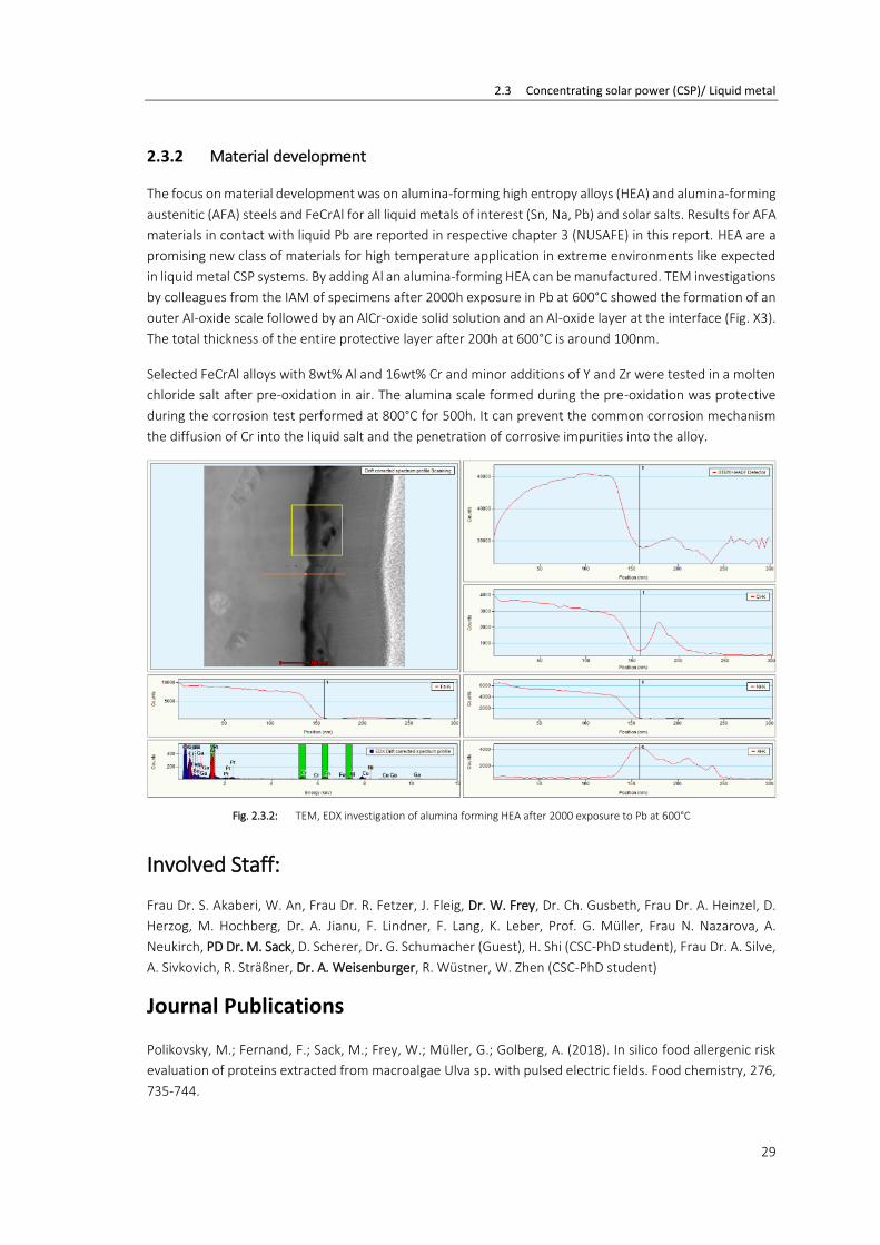
2.3.2 Material development
The focus on material development was on alumina-forming high entropy alloys (HEA) and alumina-forming
austenitic (AFA) steels and FeCrAl for all liquid metals of interest (Sn, Na, Pb) and solar salts. Results for AFA
materials in contact with liquid Pb are reported in respective chapter 3 (NUSAFE) in this report. HEA are a
promising new class of materials for high temperature application in extreme environments like expected
in liquid metal CSP systems. By adding Al an alumina-forming HEA can be manufactured. TEM investigations
by colleagues from the IAM of specimens after 2000h exposure in Pb at 600°C showed the formation of an
outer Al-oxide scale followed by an AlCr-oxide solid solution and an Al-oxide layer at the interface (Fig. X3).
The total thickness of the entire protective layer after 200h at 600°C is around 100nm.
Selected FeCrAl alloys with 8wt% Al and 16wt% Cr and minor additions of Y and Zr were tested in a molten
chloride salt after pre-oxidation in air. The alumina scale formed during the pre-oxidation was protective
during the corrosion test performed at 800°C for 500h. It can prevent the common corrosion mechanism
the diffusion of Cr into the liquid salt and the penetration of corrosive impurities into the alloy.
Fig. 2.3.2: TEM, EDX investigation of alumina forming HEA after 2000 exposure to Pb at 600°C
Involved Staff:
Frau Dr. S. Akaberi, W. An, Frau Dr. R. Fetzer, J. Fleig, Dr. W. Frey, Dr. Ch. Gusbeth, Frau Dr. A. Heinzel, D.
Herzog, M. Hochberg, Dr. A. Jianu, F. Lindner, F. Lang, K. Leber, Prof. G. Müller, Frau N. Nazarova, A.
Neukirch, PD Dr. M. Sack, D. Scherer, Dr. G. Schumacher (Guest), H. Shi (CSC-PhD student), Frau Dr. A. Silve,
A. Sivkovich, R. Sträßner, Dr. A. Weisenburger, R. Wüstner, W. Zhen (CSC-PhD student)
Journal Publications
Polikovsky, M.; Fernand, F.; Sack, M.; Frey, W.; Müller, G.; Golberg, A. (2018). In silico food allergenic risk
evaluation of proteins extracted from macroalgae Ulva sp. with pulsed electric fields. Food chemistry, 276,
735-744.

2 Renewable Energy (RE): Bioenergy-Feedstocks and Pretreatment-
30
Robin, A.; Kazir, M.; Sack, M.; Israel, A.; Frey, W.; Müller, G.; Livney, Y. D.; Golberg, A. (2018). Functional
Protein Concentrates Extracted from the Green Marine Macroalga Ulva sp., by High Voltage Pulsed Electric
Fields and Mechanical Press. ACS sustainable chemistry & engineering, 6 (11), 13696–13705.
Silve, A.; Kian, C. B.; Papachristou, I.; Kubisch, C.; Nazarova, N.; Wüstner, R.; Leber, K.; Strässner, R.; Frey,
W. (2018). Incubation time after pulsed electric field treatment of microalgae enhances the efficiency of
extraction processes and enables the reduction of specific treatment energy. Bioresource technology, 269,
179–187.
Ding, W.; Shi, H.; Xiu, Y.; Bonk, A.; Weisenburger, A.; Jianu, A.; Bauer, T. (2018). Hot corrosion behavior of
commercial alloys in thermal energy storage material of molten MgCl 2 /KCl/NaCl under inert atmosphere.
Solar energy materials & solar cells, 184, 22–30.
Akaberi, S.; Wang, H.; Claudel, P.; Riemann, M.; Hause, B.; Hugueney, P.; Nick, P. (2018). Grapevine fatty
acid hydroperoxide lyase generates actin-disrupting volatiles and promotes defence-related cell death. The
journal of experimental botany, 69 (12), 2883–2896.
Buchmann, L.; Böcker, L.; Frey, W.; Haberkorn, I.; Nyffeler, M.; Mathys, A. (2018). Energy input assessment
for nanosecond pulsed electric field processing and its application in a case study with Chlorella vulgaris.
Innovative food science & emerging technologies, 47, 445–453.
Cemazar, M.; Sersa, G.; Frey, W.; Miklavcic, D.; Teissié, J. (2018). Recommendations and requirements for
reporting on applications of electric pulse delivery for electroporation of biological samples.
Bioelectrochemistry, 122, 69–76.
Robin, A.; Sack, M.; Israel, A.; Frey, W.; Müller, G.; Golberg, A. (2018). Deashing macroalgae biomass by
pulsed electric field treatment. Bioresource technology, 255, 131–139.
Silve, A.; Papachristou, I.; Wüstner, R.; Sträßner, R.; Schirmer, M.; Leber, K.; Guo, B.; Interrante, L.; Posten,
C.; Frey, W. (2018). Extraction of lipids from wet microalga Auxenochlorella protothecoides using pulsed
electric field treatment and ethanol-hexane blends. Algal Research, 29, 212–222.
Voyer, D.; Silve, A.; Mir, L. M.; Scorretti, R.; Poignard, C. (2018). Dynamical modeling of tissue
electroporation. Bioelectrochemistry, 119, 98–11

31
3 Safety Research for Nuclear Reactors (NUSAFE): Transmutation -Liquid Metal Technology-
Contact: Prof. Georg Müller, Dr. A. Weisenburger
Long-living high-level radioactive waste from existing nuclear power reactors should be transmuted in
short-living radio nuclides using fast neutrons provided by a spallation target in an accelerator driven
subcritical system or by a fast nuclear reactor. The objective is to reduce the final disposal time of high-
level radioactive waste (plutonium, minor actinides) from some 106 years down to about 1000 years. Lead
(Pb) and lead-bismuth (PbBi) are foreseen as spallation-target and coolant of such devices.
The aim of the institute’s contribution is to develop advanced corrosion mitigation processes based on in-
situ formation of protective alumina scales especially for parts under high loads like fuel claddings or pump
materials in contact with liquid Pb or PbBi. Pulsed large area electron beams (GESA) are used to create
aluminium containing surface alloys on steels. In addition, bulk alumina formers like FeCrAl, AFA (alumina
forming austenitic steels) and HEA (high entropy alloys) are developed.
All tasks are embedded in European and international projects and cooperations like e.g., ILTROVATORE,
MYRTE, GEMMA and EERA-JPNM.
The most relevant results obtained in the reporting period are presented briefly:

3 Safety Research for Nuclear Reactors (NUSAFE): Transmutation -Liquid Metal Technology-
32
3.1 Material development and advanced corrosion mititgation for heavy liquid metal-cooled nuclear systems
Contact: Dr. Alfons Weisenburger
3.1.1 Optimizing the GESA IV facility
The GESA IV facility for the treatment of cladding tubes has a cathode and accelerator in cylindrical
configuration, which still needs to be optimized to guarantee a reproducible and reliable surface alloying
process. The optimized cathode design for higher current densities indicated a strong dependence of the
voltage division between the cathode-grid gap and the grid-anode gap. Estimations show that an optimized
design (ratio of grid and anode radius) can increase the target current by more than 30% (Fig. X1).
Electrons that miss the target and circulate in the accelerator volume negatively affect the operation
performance of GESA IV. In order to reduce the number of circulating electron, the angular distribution of
the electrons at emission needs to be minimized. This will be achieved by modification of plasma density,
mesh size of grid and electric field strength in cathode-grid gap while fixing the emission current density.
Fig. 3.1.1: Target current of GESA IV as function of the ratio of grid to anode radius.
3.1.2 Material development to mitigate corrosion
Fretting tests of wire wrapped fuel cladding samples were performed using the test facility FRETHME that
was adapted to the MYHRRA relevant geometry in the framework of the H2020 project MYRTE. The tests
were conducted at MYHRRA relevant conditions in PbBi at 400°C with a target oxygen content of 10-7 wt%.
The amplitudes of the relative movement varied between 5 and 300 µm, the loads between 5 and 75 N
and the duration between 100 h and 4080 h. The frequency was fixed to 10 Hz.
The penetration rates (µm/h) derived for the short term tests (100h to 500h) with varying loads and
amplitudes are plotted versus the working rate (Fig. 3.1.2). At small amplitudes (<10µm) the fretting depths
increases linearly with increasing load. At loads above 40N the fretting depths scales with increasing
5 10 15 20 25
1000
1200
1400
1600
1800
2000
2200
2400
Targ
et S
trom
, A
Gitterradius/Anodenradius
1704A (magic 1748A)

3.1 Material development and advanced corrosion mititgation for heavy liquid metal-cooled nuclear systems
33
amplitude. Considering a 2 year operation time (17 520h) none of the penetration rates are acceptable
considering an upper limit of 10% of the cladding wall thickness. It is known, that fretting damage is highest
at the beginning and reduces by time. Results from the long term tests of 4080h depicted in the diagram
on right side (blue dots) showed the lowest penetration rate of all experiments. The lowest rate measured
at the long-term test sample 10N/60µm/4080h with 0.0031µm/h is low enough to satisfy almost the 10%
target after 2 years for the penetration depth. In line contact, which would reduce the contact pressure
significantly, the operating time until the 10% margin can be increased significantly.
Alumina forming austenitic alloys are developed as one of the advanced corrosion mitigation strategy with
the support of the EU H2020 project GEMMA. An optimized alloy composition (Fe-(2.5-4)Al-(14.5-16.5)Cr-
(20-29)Ni + specific alloying element like Nb, W, Mo, C ….[wt.%]) was derived from corrosion tests in Pb at
550° and 600°C. Besides corrosion resistance, the AFA alloys should show ductile behaviour and are
required to be stable regarding their microstructure during long term high temperature exposure. Small
punch tests to examine the ductility of the alloys were performed by our colleagues at CIEMAT and proved
that none of the tested AFA alloys showed brittle behaviour (Fig. 3.1.3)
0,01 0,02 0,03 0,04 0,05 0,06 0,07 0,08
0,0
0,2
0,4
0,6
10-50N/20µm/500h
13-52N/45µm/300h
10-50N/5-8µm/100h
20N/35-50µm/100h
40-50N/28-50µm/100h
50-75N/35-75µm/100N
10N/35µm/100h
penetr
ation r
ate
[µ
m/h
]
work rate [W]
500h
250h
125h
100h
1000h Tim
e to p
enetr
ate
10%
fuel cla
d (
h)
10N
20N
40N
50N
50N/28µm
40N/35µm
40N/50µm
50N/40µm
75N/35µm
50N/35µm
0,000 0,005 0,010 0,015 0,020 0,025 0,030
0,00
0,01
0,02
0,03
0,04
0,05
0,06
0,07
0,08
10-50N/20µm/500h
13-52N/45µm/300h
20N/35-50µm/100h
5-10N/60µm/4080h
penetr
ation r
ate
[µ
m/h
]
work rate [W]
1250h
Tim
e to p
enetr
ate
10%
fuel cla
d (
h)
1000h
2500h
5000h
10N/60µm/4080h - 16129h = just under 2 years
9N/20µm
10N/20µm
15N/20µm
50N/20µm
Fig. 3.1.2: Penetration rate vs working rate for different fretting conditions in molten PbBi with 10-7wt% oxygen at 400°C; left side without long-term test / right side: with long-term test.
Fig. 3.1.3: Small punch test of AFA alloys showing the ductile behaviour of the new developed material.
3 Safety Research for Nuclear Reactors (NUSAFE): Transmutation -Liquid Metal Technology-
34
XRD Measurement of AFA specimens exposed for 1000h in b at 600°C do not show any formation of ferritic
phase due to the temperature and time. Small amount of ’ (Ni3(Al, Fe) that can act as aluminium reservoir
are observed in some of the compositions.
Collaboration: SCK-CEN, ENEA, KTH, SANDIVK, CIEMAT, CEA
Funding: EU-Projects and NUSAFE
Involved Staff
W. An, Frau Dr. R. Fetzer, Frau Dr. A. Heinzel, Dr. A. Jianu, F. Lang, F. Lindner, Prof. G. Müller, A. Neukirch,
Dr. G. Schumacher (Gast), H. Shi (CSC-PhD student), A. Sivkovich, Dr. A. Weisenburger, W. Zhen
(CSC-PhD student)
Journal Publications
Tang, C.; Jianu, A.; Steinbrueck, M.; Grosse, M.; Weisenburger, A.; Seifert, H. J. (2018). Influence of
composition and heating schedules on compatibility of FeCrAl alloys with high-temperature steam. Journal
of nuclear materials, 511, 496–507.
Hochberg, M.; Sack, M.; Herzog, D.; Weisenburger, A.; Müller, G. (2018). Design Validation of a Single
Semiconductor-Based Marx-Generator Stage for Fast Step-Wise Arbitrary Output Waveforms. IEEE
transactions on plasma science, PP (99), 1–7.

35
4 Energy Efficiency, Materials and Resources (EMR)
Energy-Efficient Processes -Multiphases and thermal processes-
Contact: Dr. Guido Link
Besides the activities on development of technologies and systems for the plasma heating in the FUSION
Program, IHM is also in charge of research and development in the topic Energy Efficient Processes, part
of the EMR Program.
An important part of this research is the dielectric characterization of the processed materials in the
parameter range relevant to processes under development. Therefore existing test-sets are continuously
improved and new test-set are developed following the new requirements regarding materials
compositions or process parameter range. Meanwhile a very versatile test lab for dielectric characterization
exists. This allows temperature dependent dielectric measurements in the frequency range from 10 MHz
to 30 GHz for low as well as high loss materials and from room temperature up to 1000°C for solids, liquids
and at pressures up to 20 bar.
All this expertise and the existing industrial scale high power microwave infrastructure faces growing
interest from industry and research. As a consequence the research group is involved in several national
and international joint research projects with objectives in various fields of applications. The design of an
industrial prototype reactor for the microwave assisted depolymerization of PET plastic waste, requested
by the project partner Gr3n within the H2020 project SYMBIOBTIMA, for the purpose of energy efficient
recycling, was successfully finished. This process idea gained the European Innovation Radar Prize 2018. In
the frame of the H2020 Marie Curie international training network TOMOCON a microwave tomographic
sensor is under development. Within the German-Korean project REINFORCE the potential of microwave
dielectric heating as well as microwave sustained plasma heating will be investigated with respect to energy
efficient carbon fiber production. Two more projects have been started in 2018 for the microwave assisted
and energy efficient lamination of synthetic leather for automotive industry (e-KOMFORT) and for the
microwave assisted intermittent pultrusion of CFRP profiles (IMPULS) .
Solid state microwave amplifiers getting more and more competitive compared to magnetron sources with
respect to power and costs. Furthermore such amplifiers allow precise control not only of power level but
also of frequency and phase and promise significant longer lifetime than magnetrons. Those features and
novel process control concepts might be door openers for novel application that could not be satisfied with
magnetron sources so far. Furthermore those novel microwave source might be useful for microwave
sustained plasma generators for plasma activation of CO2 in the frame of research activities like Power to
X. Therefore recently a novel lab for plasma chemistry using atmospheric microwave plasma has been
established. The status of major projects is briefly introduced in the following chapters. This new activity
gained positive feedback from the 2018 mid-term review panel for the Helmholtz Energy Program.

4 Energy Efficiency, Materials and Resources (EMR)
36
4.1 Plasma Chemistry
Contact: Dr. Sergey Soldatov
The plasma assisted conversion of CO2 into synthetic fuels based on renewable energies is considered as
promising approach for mitigation of CO2 emission and energy storage. Among different plasma discharges,
namely the microwave sustained plasmas have shown to be most efficient for CO2 splitting reaction
CO2 CO + 1/2 O2. The sustaining CO2 plasma with short, nanosecond microwave pulses rather than with
the continuous microwave power may increase the energy efficiency by shifting the thermal equilibrium in
the plasma towards vibrational excitation states. Additionally, at pulse-mode operation the plasma gas
temperature may be decreased considerably that opens the opportunity to combine the plasma activation
with catalytic one as well as with gas separation membranes.
The plasma experiment is shown in Fig. 4.1.1. It comprises a plasma coaxial torch (Heuermann HF-Technik
GmbH), a 300 W, 2.45 GHz solid state microwave generator (HBH Microwave GmbH), gas flow controllers,
a X-STREAM Gas analyzer (Emerson) and an advanced optical emission spectroscopy (OES) system. The
latter one features a high-resolution spectrograph (Acton SP-2756) with 750 mm focal length and 512x2048
pixel CCD camera (A-DH340-18U-03) with an intensifier and fast (≥2ns) gate from company LOT-QD GmbH.
In collaboration with IMVT the energy efficiency of CO2 splitting in the plasma reactor was studied by
systematic parameter variations, such as gas inflow (12, 15 and 18 slm), different duty cycles and pulse
times with a 200 W pulse magnitude. Within that first parameter scan, a maximum energy efficiency of
about 36 % war reached already for a duty cycle of 0.2 and an input gas flow of 12 slm. It corresponds to a
specific energy input (SEI) of 0.05 eV/mol. Additionally the efficiency of the process in a pulsed microwave
plasma has shown to be higher as compared with a plasma sustained with continuous microwave power.
Furthermore the combination of pulsed microwave plasma and catalysts was tested. The carrier material
of the catalyst was a cordierite honeycomb monolith. First tests demonstrated a successful operation of
the plasma reactor with the honeycomb monolith mounted in the plasma afterglow region without visible
deterioration of the catalyst.
Fig. 4.1.1: Lab setup of the plasma experiment.

4.2 e-KOMFORT
37
4.2 e-KOMFORT
Contact: M.Sc. Vasileios Ramopoulos
Comfort is increasingly a decision criterion for buying a car. High quality materials and comfort are the
interface to the user. Today, cars are fitted with up to 9 m2 of technical textiles, which make the car more
attractive in terms of look and feel. Such decorative materials have to be laminated by very energy and
time-intensive processes. With the conventional lamination technique the heat for adhesive activation is
transferred by preheated tools via heat conduction through the surface of the decorative materials or
substrate materials. Suitable microwave technology and suitable adhesives allow a direct and selective
heating and activation of the adhesive. This leads to significant energy savings of more than 70% and to
greater productivity. In Germany alone, the energy saving potential in this production area is estimated at
approx. 70 GWh/year.
The project objectives are achieved by developing suitable formulations of a reactive hot melt adhesive
and methods of applying this adhesive to the engineering fabric with sufficient uniformity and
reproducibility. A suitable measurement setup is developed to enable the identification of the most suitable
adhesive formulation (see Fig. 4.2.1). Then based on measured material properties microwave-compatible
laminating tools are being developed for the microwave-assisted lamination of the textile thus pre-coated
and prefixed to the substrate. Finally, a microwave technology is being developed, consisting of a
microwave applicator with distributed, solid state microwave sources. By a targeted adjustment of those
microwave sources in frequency, amplitude and phase the required field and temperature distribution shell
be achieved in the adhesive layer. The optimized interaction of all of these developed technologies will
demonstrate the process and its advantages on a pilot scale for selected automotive components at the
end of the project.
Fig. 4.2.1: Dielectric measurements setup for thin multilayer materials at 2.45 GHz.
Funding: 6th Energy Research Programme of the Federal Government, support code 03ET1576A

4 Energy Efficiency, Materials and Resources (EMR)
38
4.3 High power solid-state microwave generators
Contact: M.Sc. Dominik Neumaier
Microwave heating offers the possibility to reduce significantly the production cycle time and energy
consumption in heating processes compared to conventional heating methods. The main challenge of
microwave applicators in an industrial scale is the inhomogeneous dielectric heating of the products
because of standing waves inside the microwave applicator. Therefore, the advantages of microwave
heating cannot be used in every industrial application. The aim of this project is to develop a novel high
power (1 kW, 2.4 GHz to 2.5 GHz) solid-state generator in cooperation with the company HBH Microwave
GmbH (HBH) and use the advantages of this source in comparison with the commonly used magnetron
oscillators to increase the temperature homogeneity of the heated product. In comparison to a magnetron
a solid state amplifier increases the degrees of freedom of the microwave source because it’s possible to
do a precise control in amplitude, phase and frequency in a very fast way (1 ms). Furthermore, this device
also allows creating very fast pulses with a minimum pulse length of 10 ns.
The first 300 W prototype was produced by HBH and tested at KIT. A measurement setup was designed
(see Fig. 4.3.1) and simulated for testing the advantages of the designed amplifier. By changing the
frequency, it is possible to excite different eigenmodes with different heating patterns (see Fig. 4.3.1). The
measured and simulated heating patterns are very similar. An optimized superposition of different
eigenmodes increases the homogeneity of the heated workpiece. The next step is to do tests with different
materials and use also the phase and amplitude control to further increase the homogeneity.
Another interesting application of this very fast controlled microwave source is the plasma application. By
using of nanosecond microwave pulses it is possible to generate non-thermal plasmas at atmospheric
pressures, which promises maximal conversion efficiency in plasma chemistry. Magnetron oscillators do
not allow such fast pulses and therefore don’t provide this opportunity. A measurement setup was built
and different tests are actually in progress (see Chapter 4.1).
300 W Prototyp Microwave oven Measured
temperature distribution
Simulated power distribution
2.421875 GHz
2.4257 GHz
2.48322 GHz
2.4922 GHz
Fig. 4.3.1: Prototype of a 300 W solid state microwave source, Microwave oven and comparison of measured and simulated modes
Funding: ZIM cooperation project, support code ZF4204602PR

4.4 REINFORCE
39
4.4 REINFORCE
Contact: M.Sc. Julia Hofele
Carbon fibers are widely used in lightweight applications, but the carbon fiber production is rather
expensive and energy intensive compared to the production of aluminium and steel. Microwave heating
has the benefit of heating in the volume and thus may lead to faster heating rates. For this reason, the goal
of the project is to research the production of carbon fibers with dielectric heating or microwave sustained
plasma heating.
In a first step, fiber samples of conventionally stabilized PAN fibers and virgin PAN fibers provided by the
project partner KCTECH were characterized dielectrically through the cavity perturbation method. For this
purpose, a cylindrical cavity operating in the TM010 mode at a frequency of 2.45GHz was used. The results
measured at room temperature show a difference in the dielectric properties at different reaction states.
This leads to the assumption that the change in the dielectric properties allows in-situ characterization of
the stabilization process and potentially enables innovative process control. The next step was to extend
the measurement with controlled convective heating along any preset temperature profiles and measure
the dielectric properties in-situ. The set-up schematics can be seen in Fig. 4.4.1.
In Fig. 4.4.2 a first result of the set up can be seen. It is obvious from the color change over the fiber length
that the heating of the fiber is not yet homogenous due to heat losses so that the reaction also is not
uniform over the fiber length. These first results show that the system parameters have to be adjusted. It
is expected that the data acquired from the measurements will provide useful information about the
reaction kinetics, which is important for the design of a microwave assisted stabilization process.
Fig. 4.4.1: Schematic of the set up for conventional heating and measurement of the dielectric properties.
Fig. 4.4.2: Conventionally heated fiber with inhomogenous reaction over the length.
Funding: ZIM cooperation project; support code ZF4204603SY7

4 Energy Efficiency, Materials and Resources (EMR)
40
4.5 TOMOCON
Contact: Dr. Guido Link
The European Marie Skłodowska-Curie Training Network “Smart tomographic sensors for advanced
industrial process control (TOMOCON)” joins 12 international academic institutions and 15 industry
partners, who work together in the emerging field of industrial process control using smart tomographic
sensors. The network shall lay the scientific and technological fundamentals of integrating imaging sensors
into industrial processes and will demonstrate its functional feasibility on lab and pilot-scale applications.
4 out of 15 doctoral researchers at 3 European academic institutes (Chalmers University of Technology,
University of Eastern Finland and KIT), are being trained in the fields of process tomography hardware,
software and algorithms, control systems theory and design, industrial process design, multi-physics
modelling and simulation, human-computer interaction, and massive parallel data processing. Together
with their supervisors and industry partners they are engaged in the development and microwave and
electrical capacitance tomography (MWT and ECT), respectively and its application in microwave drying of
porous materials. Those are applied to detect the moisture distribution in a porous and to provide
information to get a feedback for the process control. The technology finally is planned to be demonstrated
on an industrial scale conveyor belt system for microwave assisted drying of polymer foams. In a first
approach a virtual demonstration based on Simulink software has been developed, including process
simulation, forward and inverse problem solvers for the ECT and MWT tomographic sensors as well as
algorithms for process control.
Fig. 4.5.1: Scheme of the microwave drying process and relevant process parameter to be controlled based on MWT or ECT data.
Funding: H2020-MSCA-ITN-2017; Grant agreement 764902

4.6 IMPULS
41
4.6 IMPULS
Contact: M.Sc. Moritz Engler
Pultrusion is a manufacturing process for the continuous production of fiber-reinforced polymer profiles,
where reinforcing fibers are impregnated with a thermoset resin and then pulled though a heated die,
which forces the material into the desired cross section and simultaneously cures the resin.
The IMPULS project aims to develop a microwave powered pultrusion system for the manufacturing of
carbon fiber reinforced bicycle spokes. The advantage of microwave heating compared to the conventional
heating process lies in the instantaneous volumetric heating of the structure. Since the tool surfaces are
not heated, temporarily shutting down the microwave power allows the creation of uncured sections.
Those uncured sections can then be rearranged in the desired shape cured in a secondary heating process.
This expands the pultrusion process to a variety of new applications, which are not possible with
conventional heating. A critical parameter for the usefulness of the uncured sections is the length of the
undefined transitional areas between the fully cured and uncured profile sections. To achieve sharp
transitions the heating zone of the microwave applicator needs to be as short as possible. For an applicator
operating at 2.45 GHz this requires focusing of the electric fields to a fraction of the wavelength.
To design an applicator which achieves homogenous heating over the composite cross section, good
knowledge of the electric properties of the composite is required. The material properties depend on the
type of fiber and resin as well as the fiber volume content and therefore need to be determined for the
specific application. Due to the conductive nature of the carbon fibers, unidirectional composites are highly
anisotropic, behaving as a conductor if the electric field is aligned with the fibers and as a dielectric if it is
perpendicular. For this reason a waveguide based transmission reflection method as shown in Fig. 4.6.1 is
used for the characterization of the composite. It allows the measurement of highly lossy materials and
also provides a defined orientation of the electric field, which is necessary for the independent
measurement of the parallel and perpendicular polarization.
Fig. 4.6.1: Left: Transmission reflection test stand; Right: Composite sample in test frame
Funding: BMWi, ZIM Kooperationsprojekt, support code: ZF4204604BL8

4 Energy Efficiency, Materials and Resources (EMR)
42
4.7 3D Microwave Printing of Composites
Contact: Dr. Nanya Li
Continuous carbon fiber reinforced polymer composites are widely used in land transport and aerospace
industry, because of their higher strength/weight ratio and longer service periods, compared with metal
materials. Recently, the skyrocketing demands of 3D printing of continuous carbon fiber reinforced
polymer composites stimulate the development of printing technologies. The popular printing technologies
for composite materials include fused deposition modeling, digital light printing and laser-assisted
laminated object manufacturing. Since every part can be sliced and printed in one direction, 3D printing
technologies can build nearly any kind of parts. However, traditional 3D printing of continuous carbon fiber
reinforced polymer composites lacks of abilities to manufacture parts with higher speed, cross-bars
characters and higher strength. This is due to the slow heat transfer and weak bonding disadvantages
during the traditional printing process. In this project, the 3D microwave printing technology is presented
to fabricate continuous carbon fiber reinforced composites with higher speed and improved mechanical
strength.
It is the first reported 3D microwave printer (3DMP) to manufacture parts by use of continuous carbon
fiber reinforced polymer composites. An ingenious microwave printing head by taking the carbon fibers as
a perfect microwave absorbing material was designed and manufactured. The printing path planning
method was developed for the 3DMP of continuous carbon fiber reinforced composites. Under required
load conditions, the stresses transmission path inside the composites were calculated and converted to the
printing path of the continuous carbon fiber reinforced filament. A prototype system with 10 times faster
printing speed than with conventional printing was demonstrated. This disruptive technology is clearly the
answer to the next-generation lightweight carbon fiber reinforced composites manufacturing.
Fig. 4.7.1: 3D microwave printing technology of continuous carbon fiber reinforced composites.
Funding: Alexander von Humboldt Research Project, German Federal Ministry for Education and Research
Involved Staff
L. Baureis, Frau J. Frank, M. Engler, Frau J. Hofele, Prof. J. Jelonnek, S. Layer, Dr. N. Li, Dr. G. Link, D. Neumaier, V. Nuss, A. Omrani, V. Ramopoulos, T. Seitz, S. Soldatov, Frau S. Wadle

4.7 3D Microwave Printing of Composites
43
Journal Publications
Ramopoulos, V.; Link, G.; Soldatov, S.; Jelonnek, J. (2018). Industrial scale microwave applicator for high
temperature alkaline hydrolysis of PET. International journal of microwave and wireless technologies, 10
(5-6), 709–719.


45
Appendix
Equipment, Teaching Activities and Staff
IHM is equipped with a workstation cluster and a large number of experimental installations: KEA, KEA-ZAR,
three GESA machines, eight COSTA devices, one abrasion and one erosion teststand, two gyrotron test
facilities with one common power supply and microwave-tight measurement chamber, one compact
technology gyrotron (30 GHz, 15 kW, continuous wave (CW)), several 2.45 GHz applicators of the
HEPHAISTOS series, one 0,915 GHz, 60 kW magnetron system, one 5.8 GHz, 3 kW klystron installation and
a low power microwave laboratory with several vectorial network analysers.
The project FULGOR, targeting for a renewal of the KIT gyrotron teststand is progressing. In 2013, an
agreement on the project structure including the involvement of the KIT project and quality management
has been achieved. The final start of the procurement of the equipment was in 2014.
Prof. John Jelonnek has continued to teach the lecture course entitled “High Power Microwave
Technologies (Hochleistungsmikrowellentechnik)” for Master students at KIT. Prof. Georg Müller has
continued to teach the lecture on “Pulsed Power Technologies and Applications” at KIT. Dr. Gerd
Gantenbein has been teaching the part “heating and current drive” of the lecture “Fusionstechnologie B”
by Prof. R. Stieglitz, IFRT. Dr.-Ing. Martin Sack hold the lecture course “Elektronische Systeme und
EMV” at KIT.
At the turn of the year 2018/2019 the total staff with regular positions amounted to 41 (20 academic staff
members, 10 engineers and 11 technical staff member and others).
In addition 19 academic staff members, 1 engineer and 3 technical staff members (and others) were
financed by acquired third party budget.
In course of 2018, 2 guest scientists, 12 PhD students (1 of KIT-Campus South, 11 of KIT-Campus North, 2
Scholarship, 1 in cooperation with IPP Greifswald), 1 DHBW student, 2 trainee in physics laboratory and 3
trainees in the mechanical and electronics workshops worked in the IHM. 5 Master students have been
hosted at IHM and 4 Bachelor student has been at IHM during 2018.
Strategical Events, Scientific Honors and Awards
Prof. Manfred Thumm received the “IEEE 2018 NPSS Merit Award”.
Dr. Alfons Weisenburger was part of the Innovation Award of the gas industry.
Longlasting Co-operations with Industries, Universities and Research Institutes
Basics of the interaction between electrical fields and cells (Bioelectrics) in the frame of the
International Bioelectrics Consortium with Old Dominion University Norfolk, USA; Kumamoto
University, Japan; University of Missouri Columbia, USA; Institute Gustave-Roussy and University of

Appendix
46
Paris XI, Villejuif, France; University of Toulouse, Toulouse, France, Leibniz Institute for Plasma Science
and Technology, Greifswald, Germany.
Desinfection of hospital wastewater by pulsed electric field treatment in cooperation with University of
Mainz and Eisenmann AG.
Integration of the electroporation process for sugar production with SÜDZUCKER AG.
Development of protection against corrosion in liquid metal cooled reactor systems in the following EU-
Projectes: LEADER, GETMAT, MATTER, SEARCH (Partner: CEA, ENEA, SCK-CEN, CIEMAT).
Development of large area pulsed electron beam devices in collaboration with the Efremov Institute,
St. Petersburg, Russia.
Experiments on liquid Pb and PbBi-cooling of reactor systems with the Institute for Physics and Power
Engineering (IPPE), Obninsk, Russia.
Development, installation and test of the complete 10 MW, 140 GHz ECRH Systems for continuous wave
operation at the stellarator Wendelstein W7-X in collaboration with the Max-Planck-Institute for
Plasmaphysics (IPP) Greifswald and the Institute of Interfacial Process Engineering and Plasma
Technology (Institut für Grenzflächenverfahrenstechnik und Plasmatechnologie, IGVP) of the University
of Stuttgart.
Development of the European ITER Gyrotrons in the frame of the European GYrotron Consortium
(EGYC) and coordinated by Fusion for Energy (F4E). The other members of the Consortium are CRPP,
EPFL Lausanne, Switzerland, CNR Milano, Italy, ENEA, Frascati, Italy, HELLAS-Assoc. EURATOM
(NTUA/NKUA Athens), Greece. The industrial partner is the microwave tube company Thales Electron
Devices (TED) in Paris, France.
Development of new diagnostic systems for improvement of electron guns for gyrotrons and cavity
interaction calculations in collaboration with the St. Petersburg Polytechical University, Russia and the
University of Latvia, Latvia.
Development of Microwave Systems of the HEPHAISTOS Series for materials processing with
microwaves with the Company Vötsch Industrietechnik GmbH, Reiskirchen.


ISSn 1869-9669
The Institute for pulsed power and Microwave Technology (Institut für Hoch-leistungsimpuls- und Mikrowellentechnik (IHM)) is doing research in the areas of pulsed power and high-power microwave technologies. Both, research and development of high power sources as well as related applications are in the focus. Applications for pulsed power technologies are ranging from materials processing to bioelectrics. High power microwave technologies are focusing on Rf sources (gyrotrons) for electron cyclotron resonance heating of magnetically confined plasmas and on applications for materials processing at microwave frequencies.
The IHM is doing research, development, academic education, and, in collaboration with the KIT Division IMA and industrial partners, the technology transfer. The IHM is focusing on the long term research goals of the German Helmholtz Association (HGf). During the ongoing program oriented research period (pof3) of HGf (2015 – 2020), IHM is working in the research field eneRGY. Research projects are running within following four HGf programs: “energy efficiency, Materials and Resources (eMR)”, “nuclear fusion (fUSIon)”, “nuclear Waste Management, Safety and Ra-diation Research (nUSAfe)” and “Renewable energies (Re)”.
During 2018, R&D work has been done in the following areas: fundamental the-oretical and experimental research on the generation of intense electron beams, strong electromagnetic fields and their interaction with biomass, materials and plasmas; application of those methods in the areas of energy production through controlled thermonuclear fusion in magnetically confined plasmas, in material processing and in energy technology.
Ged
ruck
t au
f fS
c-z
erti
fizi
erte
m p
apie
r