annual research report - irid.or.jpirid.or.jp/_pdf/pamphleth29_eng.pdf · dized projects and 2...
TRANSCRIPT

Annual Research Report2017
Published: July 2018
5F, 3 Toyokaiji Building, 2-23-1 Nishi-Shimbashi,Minato-ku, Tokyo 105-0003,JapanPhone Number:+81-3-6435-8601 URL http://www.irid.or.jp/en
Printed on recycled paper.

1
Major R
esearch Achievem
ents Subsidized ProjectsM
ajor Research A
chievements In-H
ouse Research
Others D
ataSheet
Greeting “The Mid-and-Long-Term Roadmap toward the Decommissioning of Fukushima Daiichi Nuclear Power Station (NPS), Tokyo Electric Power Company (TEPCO) Holdings, Inc.” was revised by the government based on the updating of the Technical Strategic Plan for 2017 Decommissioning of Fukushima Daiichi NPS, TEPCO Holdings, Inc.” by the Nuclear Damage Compensation and Decommissioning Facilitation Corporation (NDF) last September. The indication was then given that retrieving the debris from the bottom of the Primary Containment Vessel (PCV) shall take place in advance with a focus on the “Partial Submersion-Side Access Method” as the fuel debris retrieval policy. The International Research Institute for Nuclear Decommissioning (IRID) has been engaged in the research and development (R&D) of the technology required in the decommissioning of the Fukushima Daiichi NPS as an urgent issue since being established in August 2013. This has resulted in the situation with the PCV and the reactor being clarified upon as well identifying the technical issues to be overcome using the development of technology for use in investigating inside the PCV and detecting the fuel debris using cosmic rays. The Annual Research Report 2017 is intended to summarize the achievements of the R&D projects (15 subsi-dized projects and 2 in-house research) undertaken by the IRID in FY2017. We would appreciate if this report helps to cast light on the R&D achievements the IRID has been responsible for. Seven years have now elapsed since the accident that occurred at the Fukushima Daiichi NPS after the Great East Japan Earthquake and the situation has been largely improved upon when compared to just after the accident, however, the decommissioning work is about to enter a crucial phase. The IRID is committed to proceeding with our R&D on the steady and timely nuclear decommissioning in thereby fulfilling our responsibilities. We sincerely appreciate your kind guidance and continued support.
March 2018
IRID’s R&D Projects in FY2017 (Overview)
Overview of Nuclear Building and IRID’s R&D Project
R&D for Fuel Debris Retrieval
R&D for Fuel Debris Retrieval
Technology for Investigation/Analysis inside Reactor Technology for Fuel Debris Retrieval
Decontamination/Dose Reduction
Technology
Repair Technology for PCV
R&D for Treatment and Disposal of
Radioactive Waste
R&D for Treatment and Disposal of
Radioactive Waste
[Direct Investigation] [Debris Retrieval]
[Securing Stable State]
[Securing Work Environment]
[Indirect Investigation/Analysis]
Development of Technology for
Investigation inside PCV
Upgrading of Approach and
Systems for Retrieval of Fuel Debris and Internal Structures
Development of Technology for
Collection, Transfer and Storage of Fuel
Debris
Development of Technology for
Criticality Control Methods
Development of Remote
Collaboration Motion Control System
Measurement and Evaluation of Fuel
Debris Distribution inside Reactor at Fukushima
Daiichi NPS Unit 3
Development of Technology for Detailed
Investigation inside PCV
Upgrading of Fundamental
Technology for Retrieval of Fuel
Debris and Internal Structures
Development of Small Neutron
Detectors
Development of Seismic Resistance
and Impact Evaluation Methods
for RPV/PCV
Development of Repair Technology for Leakage Points
inside PCV
Upgrading the Comprehensive Identification of
Conditions inside Reactor
Development of Technology for
Investigation inside RPV
Development of Sampling Technology for Retrieval of Fuel Debris and Internal
Structures
Full-scale test for Repair Technology for Leakage Points
inside PCVR&D for Treatment
and Disposal of Solid Radioactive Waste
In-House Research (2 projects)
Subsidized Projects (15 projects)
Reactor Building
Fuel Debris
Dry Well (D/W)
Vent Pipe
Reactor Pressure Vessel (RPV)
Suppression Chamber (S/C)
Spent Fuel Pool
Torus Room Primary Containment Vessel (PCV)
Development of Technology for Fuel
Debris Analysis/ Fuel Debris
Characterization
Hideo IshibashiPresident of International Research Institute for Nuclear Decommissioning
Major Research Achievements–Subsidized Projects R&D for Fuel Debris Retrieval
Development of Technology for Investigation inside PCV ……………………………………………………………… 2
Development of Technology for Detailed Investigation inside PCV …………………………………………………… 4
Development of Technology for Investigation inside RPV ……………………………………………………………… 6
Upgrading the Comprehensive Identification of Conditions inside Reactor …………………………………………… 8
Development of Technology for Fuel Debris Analysis/Fuel Debris Characterization …………………………………10
Development of Repair Technology for Leakage Points inside PCV ……………………………………………………12
Full-scale test for Repair Technology for Leakage Points inside PCV …………………………………………………14
Upgrading of Approach and Systems for Retrieval of Fuel Debris and Internal Structures …………………………16
Upgrading of Fundamental Technology for Retrieval of Fuel Debris and Internal Structures ………………………18
Development of Sampling Technology for Retrieval of Fuel Debris and Internal Structures …………………………20
Development of Technology for Collection, Transfer and Storage of Fuel Debris ……………………………………22
Development of Small Neutron Detectors …………………………………………………………………………………24
Development of Technology for Criticality Control Methods ………………………………………………………………26
Development of Seismic Resistance and Impact Evaluation Methods for RPV/PCV …………………………………28
R&D for Treatment and Disposal of Radioactive WasteR&D for Treatment and Disposal of Solid Radioactive Waste ……………………………………………………………30
Major Research Achievements–In-House Research Measurement and Evaluation of Fuel Debris Distribution inside Reactor at Fukushima Daiichi NPS Unit 3 …………32
Development of Remote Collaboration Motion Control System …………………………………………………………32
Others–DataSheet Major Research Results in FY2017 …………………………………………………………………………………………33
List of Joint Research/Contract Research in FY2017 ……………………………………………………………………36
Major Research Facility/Equipment …………………………………………………………………………………………36
Contents
In-House
In-House

32 Annual Research Report 2017
Major Research Achievements–Subsidized Projects
Major R
esearch Achievem
ents Subsidized ProjectsM
ajor Research A
chievements In-H
ouse Research
Others D
ataSheet
►Background ►PurposeThe consideration is that the reactor cores melted and nuclear fuel exists in some parts of the reactor inside as fuel debris in the Reactor Pressure Vessel (RPV) and Primary Containment Vessel (PCV) of the Fukushima Daiichi NPS Units 1–3. Fuel debris presumably spread from the opening at the bottom of the pedestal to outside it after dropping through the bottom of the RPV into the pedestal supporting it, although the status of the fuel debris is yet have been identified.
Development of Access, Investigation Device, and System for Specific Area
►Major Approach and Results
Investigation inside the Unit 2 Pedestal (A2/A2′ investigation)An A2 investigation device, which accesses the PCV through the X-6 penetrating Unit 2 and investigates above the platform through the pedestal, and A2′ investigation device, which investigates under the platform, were developed to investigate the con-ditions within the pedestal and as a verification test of the devices. The results of the investigation revealed parts of the grating to have fallen onto the platform and deposits that look like pebbles/clay all over the bottom of the pedestal. In addition, the investiga-tion confirmed that part of the fuel assemblies had fallen, and in which deposits suspected to be fuel debris (Fig. 1).
Investigation inside the Unit 3 Pedestal (Investigation for Unit 3)A submersible type robot for use in accessing the inside of the PCV from X-53 penetration of Unit 3 and thereby investigating the internals of the pedestal was developed, and which was then used in a validation test. The results of the survey confirmed that the structures were damaged and molten material, that had presumably solidified, was attached to the structures within the pedestal. Moreover, lava-like deposits were confirmed in multiple locations within the pedestal via the verification test (Fig. 2).
Planning for Investigation of Basement Floor, Element TestContinuing on from FY2016 an element test for the measurement technology was performed. The test confirmed the capabilities of the CdTe semiconductor detector in the high dose rate environment. In addition, the technology used to measure the pedestal wall surface ology was changed from the impact elastic wave method to the low frequency ultrasound method because of the latest status of the PCV in Unit 1, and which then enabled knowledge to be gained on identifying the aggregate and bottom surface echo.
►Future DevelopmentsWe intend to perform detailed design/test manufacturing/on-site validations within the project of “Development of PCV inside Detailed Investigation Technology” and use the data obtained in this project to obtain further information on inside the PCV, and will then prepare for on-site verification of Units 1 and 2.
Regarding the conditions inside the PCV, visual images, the radiation dose, and temperature have been obtained by accessing the PCV internally via X-100B penetration at Unit 1 and X-53 penetration at Units 2 and 3.
The environment is quite severe with high doses of radiation and humidity, and limited visibility was confirmed due to the steam and accumulated water and inherent darkness. Moreover, the possibility of falling or interfering objects due to the accident also exists.
This then results in the necessity for the above issues to be resolved alongside the development of technology that enables the PCV to be internally investigated.
Fig. 2: Appearance of Submersible Type Device and Survey Route
Fig. 1: Data Obtained from A2 investigation/A2′ investigation
Solidified lava-like deposits
Underwater ROV injection Port (PCV penetration Part)
Water surfaceRPV
Access route
(Submersible type device)
Pedestal
RPV
Reactor Building
PCV
Elevation thruster
A2 Investigation: Image Processing Results Based on Data Acquired from the Pedestal Opening
A2′ investigation: Part of image data obtained under platform A2′ investigation: Tip part of investigation device
Drive thruster
Front camera
Lighting
Neutral floatation
cable
Development of Technology for Investigation inside PCVPedestal
Structure
RPV
TIP guide pipe support
Slot opening
Approx. 1m
Flat barDistortion of grating
CRD exchanger
Fallen grating part
Fallen object
Part of fuel assemblies (Upper tie plate)
Cable feed mechanism
Lookdown camera
Camera
External lighting
Dosimeter/Thermometer
CR guide tube (assumed)
CR index tube (assumed)
(Near CRD housing)
(Lower part of pedestal)
R&D for Fuel Debris Retrieval
Approx. 1m

54 Annual Research Report 2017
Major Research Achievements–Subsidized Projects
Major R
esearch Achievem
ents Subsidized ProjectsM
ajor Research A
chievements In-H
ouse Research
Others D
ataSheet
Fig. 1: X-6 Penetration Connection Structure
Isolated room
Arm
Air lock (Internal door)
Air lock (External door)
Grating
Abrasive wear jet equipmentTransport cart
Rail
Isolation valve
X-6 penetration
Dual-arm manipulator for maintenance
Arm
Enclosure
Tool, sensor Site control panel
Operation control room
X-6 Penetration Connection Structure
Fig. 2: Perforation Device for X-2 Penetration (Air Lock) Internal Door
Fig. 3: Arm Type Access Unit
►Background ►PurposeThe reactor cores have been considered to have melted and nuclear fuel to exist in some parts inside the reactors and as fuel debris in the Reactor Pressure Vessels (RPV) and Primary Containment Vessels (PCV) in the Fukushima Daiichi NPS Units 1–3. The PCVs were internally investi-gated: outside the Unit 1 pedestal (B1/B2 investigations), inside the Unit 2 pedestal (A1/A2/A2′ investigations) and inside the Unit 3 pedestal using a small submersible ROV (Remotely Operated Underwater Vehicle), thus providing very valuable information. However, this did not satisfy the requirements with respect to the fuel debris retrieval because the existing opening has restrictions to it.
Development of Access/Investigation Devices
Applicability Validation of Element Technology
►Major Approach and Results
Establishing Access Route into PCV via X-6 PenetrationThe basic design of an X-6 penetration connection structure (Fig. 1) that is operated by remote control from an isolated room, which was studied in the FY2016 project of “Development of Technology for Investigation inside PCV”, has been completed. After the basic design was completed a more detailed design and test manufacturing were then commenced upon.
Establishing Access Route into PCV via X-2 PenetrationDetailed designs and test manufacture of equipment related to establishing an access route into the PCV via X-2 penetration (Air lock) (Abrasive Wear Jet Equipment for use in perforating the grating and air lock door, etc.) for Unit 1, which is a high dose area near the X-6 penetration, have been completed. On-site validation (function test) was then commenced upon (Fig. 2).
Access/Investigation DeviceAfter selecting an arm type access device, which is able to move through the air to gain access from the X-6 penetration internally into the PCV of Unit 2, a detailed design and test manufacture were commenced upon (Fig. 3).
Measurement technology to be installed on the access unit was reviewed based on an updated survey plan, and test manu-facturing has been commenced upon toward the compatibility validation of size/shape measurement technology and radiation measurement technology.
►Future DevelopmentsWe intend to continue to establish an access route into the PCVs and perform detailed designs, test manufacturing, and on-site validation of devices for use in detailed investigations of inside the PCVs and preparing for site validations at Units 1 and 2.
“The Detailed Investigation inside PCV” project that follows the existing “Investigation inside PCV” project requires an investigation through a larger access route in the PCV by enlarging the investigation device and upgrading the mea-surement technology to be installed on the device in thereby obtaining the necessary data for the fuel debris retrieval process.
For this reason, the urgent priorities are obtaining informa-tion on a method of retrieving the fuel debris and a detailed design of a fuel debris retrieval device, along with estab-lishing an access route into the PCV as well as developing technology for a detailed investigation of inside the PCV in thereby fulfilling the aims of the surveys.
Development of Technology for Detailed Investigation inside PCV
R&D for Fuel Debris Retrieval

76 Annual Research Report 2017
Major Research Achievements–Subsidized Projects
Major R
esearch Achievem
ents Subsidized ProjectsM
ajor Research A
chievements In-H
ouse Research
Others D
ataSheet
Overview of Investigative Method with Access from the Top
Investigation with Access from the Side: Appearance
Equipment carry-in entrance
Guide pipe
Air lock cell
Tool box cart
Operation floor in reactor
building
Work cell
Suspension device stored in tool box
For investigation device
For processing reactor internals
Isolation valve
ACx connection part
For full-scale survey
For preliminary confirmation
Spare nozzle cutting device
AWJ tool head
PCV head connection part
Tool box
PCV head
Shroud headRPV head drilling device
Investigation device for inside reactor
Reactor internals drilling device
Guide pipe
SealSimulated PCV headBoundary function
maintenance device
RPV head
Steam-water separator
Steam dryer
PCV
RPV
Biological shield wall
Reactor building
Working cell
AC0 cell fixed on east wall surface of reactor building
ACx cell (used for replacing AC0 cell) with tool (excavation, guide pipe insertion, sealing installation)
►Background ►PurposeInformation on the fuel debris and inside the Reactor Pressure Vessels (RPVs) needs to be obtained in advance and includ-ing their location, shape, and the internal situation. However, directly obtaining the information is difficult because RPVs have internally complicated structures and extremely high radiation levels.
Development and Selection of Methods of Investigating the Reactor Core
System Design and Planning Methods for Overall Investigation Device
Development of Equipment to Access Reactor Core►Major Approach and Results
Development of Equipment to Access the Reactor Core from the top
-1 Development of Drilling Device to Access through RPV HeadA possible method was confirmed by reviewing the work plan, specifications, and test manufacture of a device assuming that the well cover, Primary Containment Vessel (PCV) Head, and RPV Head would need to be drilled through in establishing an access route to inject the device which will then require investigating whether the device is able to enter from the operation floor on the upper part of the RPV up to the reactor core of the RPV. In addition, and regarding the RPV Head processing device, an element test for the removal method of RPV Head spare nozzle located in the access route was conducted to avoid any interruption in the internal structures of the RPV, and remote processing/workability confirmed.
-2 Development of Boundary Function Maintenance Device/Access Work DeviceIn order to access the RPV without compromising the boundary function (contamination prevention system) and maintaining a negative pressure environment, and assuming the installation of an access device for the work (work cell) on the operation floor and connection to the PCV head via a guide pipe, the possibility of method was confirmed by reviewing the work plan, equipment specifications, and a sealing property element test.In addition, specifications for a work cell were clarified with respect to the connection method of the tool box that will contain the processing equipment and survey equipment, and the carry-in/out and transport method for each equipment.
-3 Development of Device for Drilling through Upper Grid PlateAssuming a need to drill through the reactor internals (steam dryer, steam-water separator, and shroud head) from the operation floor to the upper grid plate just below the perforation position of the RPV head, the feasibility of a method was confirmed by reviewing work plan, equipment specifications, and test manufacturing.Assuming a need for remote processing in a narrow part of the RPV, an element test of a mock-up facility was performed com-bining an Abrasive Wear Jet (AWJ) Cutting Device and access equipment installed in a work cell, and the possibility of remote cutting then confirmed.
Development of Method of Accessing from SideAn access route into the reactor core from the side of the reactor building was determined upon, and concepts of the methods for use established that included selecting the applicable tools for excavation and sealing work. In addition, the specifications for all the equipment were clarified, including the design of a facility for use in maintaining the equipment.
Two kinds of specifications for investigation devices in prior confirmation of access routes via a small diameter opening and an actual investigation via a large diameter opening were studied besides the investigative steps, visibility, and radiation resistance being confirmed by an element test. In addition, an accessibility test using a mock-up facility that simulated openings was per-formed and the remote workability confirmed. The expansion mechanism in investigating the deepest part of the reactor core via horizontally accessing the center of the reactor core from the upper grid in the shroud head was test-manufactured, and the feasibility of the mechanism then confirmed by an element test.
An exposure evaluation during an investigation after accessing the PCV from the side was conducted under the current micro-positive pressure situation in the PCV. Moreover, An exposure evaluation during an investigation method via access from the top is being planned for after the establishment of negative pressure and from the aspect of any spreading of the contamination caused by dust diffusion due to the large amount of the reactor internals that radioactive material is assumed to be adhering to.
►Future DevelopmentsToward the design of the applicable device for on-site investigations, an element test on the workability will be conducted as nec-essary based on the environmental information and conditions at the work site, and the test results reflected in the design of the device. Furthermore, coordination with the related construction work required for the device design, facilities, and the utility supply system required for the site survey, along with the applicability of the incidental system, will be reviewed.
Making progress with future decommissioning, including fuel debris retrieval in a safe and smooth manner, necessitates amassing information on the currently unclear situation. Therefore, the investigative targets will be clarified based on the relevant information, and feasible technology developed for the investigation that requires a method of perforating the reactor core by it accessing from the top or the side of the RPV.
Development of Technology for Investigation inside RPV
R&D for Fuel Debris Retrieval

98 Annual Research Report 2017
Major Research Achievements–Subsidized Projects
Major R
esearch Achievem
ents Subsidized ProjectsM
ajor Research A
chievements In-H
ouse Research
Others D
ataSheet
Fig. 1: Diagram of Estimated Fuel Debris Distribution (Example of Unit 3)
Fig. 2: Plasma Heating Test of Simulated Fuel Assemblies
Fig. 3: Example of Analysis Sample and Analysis Results
Electronic microscope image
Test equipment appearance Test result example
Appearance of analytical sample
Deposits in Unit 1 PCV
Fuel rodExplanatory notes
Damaged control rod guide pipe
As of February 28, 2018
Oxidation debris (porous) Integral control rod
drive mechanismParticulate debris Control rod drive
mechanism (debris inside)Concrete mixed debris Integral shroud
PelletIntegral control rod guide pipe
RPV damage
Electronic microscope image
Appearance of analytical sample
Curing sheet in Unit 2
• Estimating the amount of energy from the PCV pressure rise due to the hydrogen occurrence and most of the fuel may have melted (Actual measurement/analysis).
• The assumption was that fuel debris in the reactor core would be minor (less than in Unit 2) because no temperature increase was observed in the RPV when the reac-tor core spray system stopped during December 9–24, 2013 (total amount injected was constant through increasing flow from the water supply system) (Actual measurement).
• The assumption was fuel debris may have existed in the lower part of the plenum because the temperature in the RPV lower decreased when the total amount of water injected was increased (September 1, 2011) from the reactor core spray system (Actual measurement).
• Part of Fuel rods may be present in the outer reactor core (General assumption).
• Melted debris may be generally solidified through oxidation (General assumption).
• The current shroud might be damaged and/or sound (General assumption/analysis).
• The increase in fuel temperature in the outer area may not be high and the pellet may be in the outer area (General assumption/test/analysis).
• The suspected control rod guide pipe have penetrated the RPV and the RPV may have a damage hole in it the size of the control rod guide pipe (Actual mea-surement).
• Water has been confirmed in the pedestal of the RPV and the outer. The damaged opening may be present in the center of the RPV and outer area (Actual mea-surement).
• Explosions occurred at Units 3 and 4. The consider-ation is that hydrogen generated from the MCCI may have caused the explosions (Actual measurement).
• Water may have accumulated on the dry well floor during the RPV damage because the dry well was sprayed for more than one hour from 07:39, March 13, 2011. This may have inhibited the spread of the fuel debris (Actual measurement, general assumption).
• Fuel debris may have spread to the outside of the ped-estal through the pedestal opening and did not reach the shell (Actual measurement, analysis).
• The case that water accumulated on the PCV floor leads to the possibility of particulate debris (General assumption).
• The case of particulate debris leads to the possibility of accumlation in the stagnant part (General assump-tion).
• The heat transfer from fuel debris is rather small and part of the control rod guide pipe may not have melted (General assumption).
• Particulate debris and pellets may have accumulated in the stagnant area (General assumption).
• Muon measurement results indicate that a mass of fuel debris may not be present in the original reactor core region (Actual measurement).
• Muon measurement results indicate that part of the fuel debris may remain at the bottom of the RPV (Actual measurement).
• The suspected solidified molten material in the lower pedestal and fallen grating and deposits were confirmed (Actual mea-surement).
• Debris may have entered into the con-trol rod drive mechanism due to damage of the control rod guide pipes (General assumption).
• Part of the fuel debris may have solidified without causing MCCI (General assump-tion).
• The investigation results inside the PCV confirmed the pedestal is internally dam-aged compared with Unit 2. The amount of fuel debris that has fallen into the PCV is larger than at Unit 2 (Actual measure-ment).
• It was confirmed that the control rod drive mechanism housing support bracket had damaged and solidified molten material had adhered around where the fuel debris may be present (Actual measurement).
►Background ►PurposeIdentifying the conditions inside the reactor and Primary Containment Vessel (PCV) is essential in establishing a method of retrieving the fuel debris and developing safety measures. However, a direct survey of and observation within the reactor are difficult because the radiation levels within the reactor at the Fukushima Daiichi Nuclear Power Station (NPS) Units 1–3 are extremely high.
This project aims at a steady approach to the decommis-sioning of the Fukushima Daiichi NPS. The conditions therefore inside the reactor and PCVs are being estimated using comprehensive analysis and evaluations based on information gained through accident progression analysis and other research and development (R&D), and analysis of measured data such as the pressure, temperature, and other information during the accident. This is a joint project with the Institute of Applied Energy.
Upgrading the Comprehensive Identification of Conditions inside Reactor
Comprehensive Analysis/Evaluation of Reactor Internals
Fuel Debris/FP Behavior and Characterization in Comprehensive Analysis and Evaluation
►Major Approach and Results
Comprehensive Analysis/Evaluation Based on Actual Data and Results from other ProjectsUsing the assumed conditions inside the Reactor Pressure Vessels (RPV)/PCV of all the units an information summary map, which summarizes the various types if information from the RPV, PCV, and reactor building, was created. The information was then comprehensively analyzed and evaluated, and used to provide an estimate diagram of the fuel debris distribution (Fig.1), an estimate of the FP (Fission Products) distribution, and an estimate of the radiation dose distribution. Establishment of Database Required for Comprehensive Analysis/EvaluationAn English language search system for the database was added and graphic display system for the measurement data, although mainly for the 3 weeks after the accident, improved in promoting the utilization of expertise from overseas organizations. In addi-tion, the database with search tags established in this project and information are being updated in contributing to more compre-hensive analysis and effective evaluation, as described in .
Reduction of Uncertainty Using Analysis MethodSensitivity and other analysis taking into consideration the boundary conditions and an analysis model for events assumed to have occurred within the reactor were conducted using the accident progression analysis code, and which then provided expertise that will contribute to the more comprehensive analysis/evaluation described in . For example, continuing on from the last fiscal year a simulated fuel assembly plasma heating test (Fig. 2) was performed, which provided expertise leading to reducing the uncertainty of events such as the core meltdown and movement within the BWR fuel assembly system. Evaluation of FP Chemical PropertiesIn evaluating the FP chemical properties, and with a focus on Cs, which is largely contributing to the radiation dose during the decommissioning, a study has commenced upon the distribution of Cs and its chemical properties, including identifying the chem-ical species that need to be considered in addition to standard chemical species such as Csl and CsOH, and the insoluble Cs particles whose production has been confirmed in the environment, and the possibility of uneven Cs distribution associated with the reaction in the upper structures of the RPVs. In addition, on-site test samples have been analyzed, and a study of the compo-sition and spatial distribution of uranium and FP conducted from the aspect of identifying the conditions inside the reactor (Fig.3). Utilization of Domestic/Overseas Knowledge through International Joint ResearchThe International Joint Research (OECD/NEA BSAF Phase2) project involves the sharing of accident progress scenarios and plant information with overseas organizations by utilizing the database that was established and which is shown in , and the evaluation results of the accident progression and debris/FP distribution by participating organizations being compared to actual measured values and the results of site surveys. The results confirmed that the deviation in analytical results of the organizations could be significantly reduced when compared with Phase-1 through a better common understanding of the progression of the accident and plant conditions, and the evaluation results of the FP emission amounts to be consistent with the amounts emitted into the environment. The estimate accuracy of the fuel debris distribution was improved via more thorough knowledge of the progression of the accident. The expertise obtained through discussions with overseas organizations was utilized in the compre-hensive analysis and evaluations described in in .
►Future DevelopmentsThis project will be completed at the end of FY 2017 (end of March, 2018). Tokyo Electric Power Company Holdings, Inc. intends to continue comprehensive analysis and evaluations that reflect the results of site surveys results in then estimating the conditions within the RPVs and PCVs in the future.
R&D for Fuel Debris Retrieval

1110 Annual Research Report 2017
Major Research Achievements–Subsidized Projects
Major R
esearch Achievem
ents Subsidized ProjectsM
ajor Research A
chievements In-H
ouse Research
Others D
ataSheet
With regard to the large MCCI test products produced in FY2016, the porous regions and metal layers were observed with their uneven status. The results of analyzing each layer revealed that the test samples, mainly consisting of the upper part of the crust and lower part of the oxidized product layers consisted of U-Zr oxidation and other products in a high Si containing (containing Ca, Al) matrix. In addition, the discovery was made that the metal block at the bottom of the boundary consists of an alloy which mainly consists of Fe.
The steam pressure of oxides to be generated to counteract the nuclides that will have a significant impact on the environment was calculated. With the fuel debris dry heat treatment the conditions of the volatile fuel uranium oxides are yet to have been determined and hence chemical compounds with higher steam pressures than UO3 pressure are being focused upon. Meanwhile, the off-gas treatment needs to be considered as all the high volatile FPs such as Cs will get emitted. The compounds that therefore have a lower steam pressure than Cs but a higher steam pressure than UO3 were selected as the candidate medium volatile FPs and included Te, Sn and Cd.
Fig. 1: Element Distribution of Large MCCI Test Products
Element map of upper part of crust cross-section
Cross sectional element map of lower part of oxidized product layer
Element map of bottom part boundary cross-section
Fig. 2: Calculation Results of Steam Pressure of Oxidized Products
Upper part of oxidized product layerLower part of oxidized product layer
Cs
TeO2
UO3SnO
CdO
Upper crust
Side boundary
Bottom boundary (metal)
Ste
am p
ress
ure
[atm
]
Temperature [K]
Development of Technology for Fuel Debris Analysis/Fuel Debris Characterization
R&D for Fuel Debris Retrieval
►Background ►PurposeThe reactor at the Fukushima Daiichi NPS was internally investigated in studying fuel debris retrieval methods and the collection/storage of it after it has been retrieved. Progress with safe and steady decommissioning work will necessitate identifying the characteristics of the fuel debris generated in the reactor. In addition, technology needs to be developed for use in analyzing fuel debris samples.
This project is aimed at surveying and assuming about the characteristics of the fuel debris that include the hardness of the fuel debris, which will be useful in studying the necessary retrieval device, and the behavior of the dry fuel debris, which will be necessary in studying the collection/storage of fuel debris and in order to provide information for the project that will be about proceeding with the actual decommissioning work. In addition, the properties of the fuel debris, which consists of complicated materials that include fuel, structural materials, and concrete, will be promptly and accurately clari-fied, and analysis technology prepared for updating the “Fuel Debris Property List”.
Assumption of Fuel Debris Properties
Characterization via Use of Simulated Debris
Development of Elemental Technology for Fuel Debris Analysis
►Major Approach and Results
A surface dose rate evaluation method for the fuel debris was studied and test evaluations of the surface dose rate of fuel debris sample cases performed. In addition, the “Fuel Debris Property List”, which involves fuel debris property assumptions, was updated using the results of analysis of large scale MCCI (Molten Core Concrete Interaction) test products obtained in FY 2017.
The necessary element technology was selected and technology for fuel debris analysis is being developed. And with regard to the melting of the fuel debris and development of a multi-element analysis method, confirmation took place that components derived from the structural materials of the fuel debris, including Cr2O3 and Fe3O4, could be melted using the alkali fusion method. In addition, results of analysis using the multi-element simultaneous analysis method and the inductively-coupled plasma emission spectrometry device (ICP-AES) with MOX simulated debris proved to have high levels of repeatability.Fuel debris analysis technology using an X-Ray CT was developed, and porosity measurements and simulated debris samples performed with the same porosity measurements as with an optical microscope. The components of samples proved capable of being clarified using the methodology of a combination of X-Ray CT and γ-Ray tomography and test samples with a mix of spent fuel and covering materials (mixed melted sample materials).With regard to the development of technology for the multiple nuclide rationalization analysis method using an induction coupling plasma mass spectrometer (ICP-MS), interfering ions with the nuclide measurements were specified and target values determined for their removal, and an impact reduction method for the hindering nuclides (Nb, Mo). A removal method is also being studied.In addition to the above achievement’s analysis items were examined and an analysis procedure was prepared for the fuel debris sampling that is presumed to be taking place to be conducted at the existing analysis facility in Ibaraki Prefecture.
Evaluation for Characterization of Uneven MCCI ProductsLarge MCCI test products were analyzed that had been produced in the test facility owned by the French Alternative Energies and Atomic Energy Commission (CEA) in FY 2016, and for use in obtaining information which includes an element map of MCCI test product layers (Fig. 1), and the crystal structure and hardness, etc. Confirmation took place that no significant change in the estimation is needed based on the basic test results so far, even if after taking the conditions at the Fukushima Daiichi NPS into consideration.In addition, expertise related to the time variation with concrete erosion shapes was obtained by analyzing data obtained from the MCCI test. Emission Behavior Evaluation of Fission Products during Dry Heat TreatmentThe emission behavior of Fission Products (FPs) was studied for use in the design of an off-gas facility and the dry treatment which is under consideration as method of pretreatment when the fuel debris is stored. A reference investigation was performed with regard to the FP emission behavior via heating in FY2017, and a medium volatile FP candidate that has a large impact on the envi-ronmental emission evaluations selected (Fig. 2). In addition, confirmation took place that emission start temperature/emission speed could be clearly measured using a thermogravimetric device/differential thermal analyzer and test samples containing Ru.
►Future DevelopmentsThe dose rates on the surface of the fuel debris are continuing to be evaluated for use in assumptions regarding the charac-terization of the fuel debris and the results will be reflected in the “Fuel Debris Property List”. In addition, and regarding the FP emission behavior evaluations during dry heat treatment, the emission behavior of selected medium volatile FPs will be evaluated. Furthermore, the development of a multiple nuclide rationalization analysis method using the ICP-MS is intended for use in estab-lishing a method of reducing the impact of any interfering ions. An analysis procedure is being examined in combination with the flow of the overall analysis. In addition, transporting the fuel debris samples will be studied.

1312 Annual Research Report 2017
Major Research Achievements–Subsidized Projects
0 1 2 3 4 5 60
0.10.20.30.40.5
0 1時間[h]
圧力
[MPa
]
0 1 2
Major R
esearch Achievem
ents Subsidized ProjectsM
ajor Research A
chievements In-H
ouse Research
Others D
ataSheet
Fig. 3: Conceptual Study of Environment Improvement for the Applicable Repair Method (Example)
Fig. 2: Overview of Repair of Lower Part of PCV (Vacuum Breakage Line Filled)
Fig. 1: Overview of Repair of Lower Part of PCV (Filling in Vent Pipe and S/C)
Repair material
Water stoppage material
Rubber material pressure test
Vent pipe 1/1 scale test
Bentonite sludge water
Welding device
Ambient dose rate
Total dosage, 36% reduction
Total dosage: 45% reduction
Exposure during repair work
Exposure with environment improvement
Environment improvement
2.6Sv
51.5Sv
30.5Sv
33.2Sv
Pre
ssur
e [M
Pa]
Exp
osur
e am
ount
Concrete water stoppage test
Guide pipe
500A×2000mm×2Steel pipe tilt angle: 20 degrees
115mm×95mm×750mmParticle size of aggregate:
minimum 7mm
Rubber material injection port
Flexible guide pipe
Vacuum breakage valve
Water stop plug
Overview of Water Stoppage Plug
Drawing of water stop plug for vacuum breakage line
Water Pressure Test Results (check valve side)
No leaking water
Exposure Evaluation with Water Stoppage Repair work (Unit 2)
Review of total dose reduction during repairs (Unit 1)
Increasing surface pressure
Front arm
Compressing all the parts
Rear armBalloon
Water stoppage material (injecting in step 1)
Water stop plug
Bellows
Water stop plug insertion device
S/C water filling stoppage device • Placement locations: 7→4• Shared camera and perforation for
injectionCamera deviceWater stoppage work area
*Self-injecting concrete composition test was conducted at Kochi University of Technology (Ouchi laboratory)
Development of Repair Technology for Leakage Points inside PCV
R&D for Fuel Debris Retrieval
►Background ►PurposeThe assumption is that melted fuel has not only fallen within the Reactor Pressure Vessel (RPV) but has also reached the Primary Containment Vessel (PCV) at the Fukushima Daiichi nuclear power station (NPS). In order to retrieve fuel debris, the plan is to accumulate water in or inject water into the PCV. Water will therefore need to be prevented from leaking from the PCV.
This project aims at establishing repair technology for the water leakage points of the PCV in order to substantiate a fuel debris retrieval method by submersing it in or injecting water into it.
Process Study and Plan for Submersing PCV
Development of Repair Technology for Lower Part of PCV
Development of Repair Technology for the Upper Part of PCV
Conceptual Study of Environment Improvement toward Applicable Repair Method (Fig. 3)
►Major Approach and Results
Reinforcement/Water Stoppage Technology for Suppression Chamber (S/C) and Vent Pipes-1 Reinforcing Technology for S/C Support ColumnsThe effectiveness of the reinforcement was confirmed based on the results of evaluating the strength after placing reinforcement materials in a full-scale mock-up facility, flow analysis, and simulations performed in FY 2017.-2 Water Stoppage Technology via Filling in Vent Pipes (Fig. 1)Water stoppage materials using radiation resistant rubber and self-injecting concrete, and repair materials using sludge water were developed in securing water stoppage capabilities. The workability and water stoppage capabilities were confirmed in a 1/1 scale test using self-injecting concrete as the water stoppage material.-3 Water Stoppage Technology via Filling in S/C (Fig. 1)A function validation test on the S/C guide pipe implementation required in inserting the hose for the concrete injection, the water level control, and water drainage in the S/C were performed in confirming their workability.
Water Stoppage Technology via Filling Vacuum Break Line (Fig. 2)Installation of water stoppage plugs and a plug insertion device through the flexible guide pipe were improved upon, and a work-ability test using a 1/1 scale test facility performed in thereby confirming their water stoppage capabilities. No leakage was con-firmed at 0.45 MPa (fully submersed condition) during a water pressure resistance test.
Boundary Formulation Technology for Connecting PipesDevelopment of water stoppage materials for the inside/outside of the various connection pipes and a repair method, and element development of remote construction and an access devise were performed in confirming the feasibility of the method.
In order to retrieve the fuel debris in a dry condition, several feasible PCV water levels were proposed based on guidelines that including the purpose of repairing the PCV, the safety requirements, work exposure levels, and seismic capacity, and the target of the water stoppage capabilities of the individual repair technologies determined.
Water Stoppage Technology for Sealant Part (equipment hatch)Abrasion of the equipment hatch water stoppage device, each of the welding heads, and the access device were studied with view to their improvement, and with the workability of the sealing method then enabling their improvement.
The radiation exposure during the water stoppage work needed to repair the lower part of the PCV was evaluated, and a method of reducing the radiation exposure by decreasing the amount of water stoppage work and the place studied in thereby identifying the issues that need to be solved. In addition, the exposed dose reduction effect through improving the environment was also confirmed.
►Future DevelopmentsIn order to establish a fuel debris retrieval policy for each of the units, repair and water stoppage technology will be reevaluated as part of an investigation of the PCV internals and studying the fuel debris retrieval method, and in case the prerequisites and conditions change.
Time [h]

1514 Annual Research Report 2017
Major Research Achievements–Subsidized Projects
Major R
esearch Achievem
ents Subsidized ProjectsM
ajor Research A
chievements In-H
ouse Research
Others D
ataSheet
Fig. 1: Overview of Test Facility
Photo-2: Implementation of Vent Pipe Water Stoppage Workability Verification Test
Photo-1: Implementation of S/C Support Column Reinforcement Test
Photo-3: Supplying Water Stoppage Material for Injecting Filling to Stop Water inside S/C
Photo-4: Operating Panel of VR System and 3D Screen
Vent pipe
Vent pipe
Upper part of torus room wall surface Cross-section of PCV lower part Inside of S/C
►Plants to be simulated:
►Facility to be simulated:
►Test facility size:
Units 2 and 3
1/8 of the area of the torus room wall surface and the lower part of the PCV
Approx. 18 m × approx. 20 m × approx. 12 mDown-comer
Down-comer
Quencher
Quencher
appr
ox.
12m
approx. 20m
approx. 18m
Suppression Chamber
Suppression Chamber
Torus room wall surface
Unit S/C volumeS/C cross-sectional diameter
Center diameter
of S/C ring
Unit 1 Approx. 4800 m3
Approx. 8 m
Approx. 30m
Unit 2-3 Approx. 6500 m3
Approx. 9 m
Approx. 35m
Full-scale test for Repair Technology for Leakage Points inside PCV
R&D for Fuel Debris Retrieval
►Background ►PurposeThe Fukushima Daiichi NPS has a severe environment with high doses of radiation and narrow spaces. There is a number of places where it is extremely difficult for people to access and do the necessary decommissioning work. This then necessitates the development of a method of repairing and stopping the water leaking from the Primary Containment Vessel (PCV), and for a remote operation device for use in retrieving the fuel debris.
A full-scale test to validate the technology and operational training was conducted in order to apply the technology developed to repair and stop the water leaks on site (methods and remote operation device, etc.). This project is taking place at the Naraha Remote Technology Development Center that was organized by Japan Atomic Energy Agency (JAEA).
Full-scale Test of Repair Technology for the Lower Part of PCV
VR Data Preparation for Preliminary Simulation Test
►Major Approach and Results
A full-scale test using a test facility (Fig.1) was conducted with respect to the following items.
Suppression Chamber (S/C) Support ColumnsA test wherein high-fluidity reinforcement materials were placed and injected into the lower part of the S/C was conducted in con-firming its feasibility using the assumed procedures and the actual situation. In addition, the feasibility of the operation monitoring, including the installation height, was also confirmed (Photo-1).
Vent Pipe Water StoppageA workability verification test was conducted in which interfering objects were removed and the vent pipes perforated via remote operation. Accessibility to the operation area was thereby confirmed with the actual situation (Photo-2).
Water Stoppage by Filling S/C (Down-comer Water Stoppage)A workability verification test confirmed that there is no problem in the facility with the applicability of the prepared remote oper-ation, the repair of the PCV, and work in the high dose environment. In addition, improved workability was considered based on the knowledge obtained from the test.
The operation monitoring feasibility, including installation height, was also confirmed using the assumed procedures in the actual situation (Photo-3).
A remote operation device to be used for stopping the water in the vent pipe was duplicated using a virtual reality (VR) system for the operational training environment as below. • Operation measurements of remote device via motion capture, etc. • Operation comparison validation with remote device and VR system reflecting its operating data.VR system effectiveness evaluation during operational training was performed (Photo-4).
►Future DevelopmentsTechnology for strengthening the S/C support columns and stopping the water in the vent pipes and by filling in the S/C requires the identification and clarification of the issues with practical application based on the results of full-scale tests. Vent pipe water stoppages are being prepared for via placement tests. VR data for preliminary simulation tests will then be completed for use in establishing training environments for remote device operators.

1716 Annual Research Report 2017
Major Research Achievements–Subsidized Projects
Major R
esearch Achievem
ents Subsidized ProjectsM
ajor Research A
chievements In-H
ouse Research
Others D
ataSheet
Fig. 2: Installation Image of Fuel Debris Retrieval Cell
Fig. 1: Scope of Element Technology Development for System Formulation
Equipment transport cart
Liquid system (Overall image) *
Gaseous system (Overall Image) *
Waste transport cart
Waste transport cell
Waste carry-out cell
Equipment carry-in crane
Cell transportation system
Fuel debris carry-out cell
Transport cell
Maintenance cell
Pathway (access tunnel)
PCV
Fuel debris retrieval cell
Equipment cell
: Range of Component Technology Plan in this Project
: Reflected range of development results from Criticality Control PJ
Monitoring system
Pretreatment system
Pretreatment system
Pretreatment system
Pretreatment system
a
Exhaust port
Exhaust port
Boric-acid water tank
Boric-acid water tank
Boric-acid water injection pump
Boric-acid water supply pump
Supply pump
Water injection pump Water injection
source
Supply water source
From water treatment facility
To water treatment facilityCooling
unit
Cooling unit
From torus room
Circulation pumpBuffer tank
Torus room intake pump (regular/
emergency use)
D/W intake pump (regular/
emergency use)
S/C intake pump (regular/
emergency use)
To buffer tank
Criticality monitor
Criticality monitor
Dust monitor
Dust monitor
Hydrogen densitometer
Hydrogen densitometer
Exhaust fan
Exhaust fan
Particle removal
filter
Particle removal
filter
Particle removal
filter
Monitoring system
Particle removal system (HEPA Filter)
Dissolved nuclide
removal facility
Particle removal facility
Particle removal facility
Boric-acid adjustment
device
To water treatment facility
To water treatment facility
Emergency buffer tank
Particle removal facility
Particle removal facility
Particle removal facility Nitrogen supply system
Nitrogen supply systemIn-leak from negative PCV pressure
Confinement technology via differential pressure control* PCV repair technology developed by other PJ
* This drawing is an example installation that satisfies the functional requirements and has no specified installation location (inside/outside the R/B) for the equipment nor an equipment model.
Monitoring instrument abbreviationL: Water level gaugeT: ThermometerP: Pressure gaugeF: Flow metern: Neutron monitorR: Radiation monitor
“Explanatory notes” Blue: Regular use system Red: Emergency use system Green: Monitoring system
Upgrading of Approach and Systems for Retrieval of Fuel Debris and Internal Structures
R&D for Fuel Debris Retrieval
►Background ►PurposeThe status with the fuel debris in the Reactor Pressure Vessels (RPVs) and Primary Containment Vessels (PCVs) of the Fukushima Daiichi NPS is currently ensuring stable cooling. However, the reactor buildings, RPVs, and PCVs were damaged in the accident and the plant itself is unstable.The aim is to retrieve the fuel debris from the unstable condi-tions and establish safer conditions by preventing the spread of any radioactive material.
The technology for upgrading the approach and a system to use in retrieving the fuel debris and internal structures has safety issues: ensuring the confinement function, capturing and removing the dust derived from the fuel debris, and the monitoring of alpha-nuclides (collective term for the radioac-tive nuclides that release alpha rays). This project aims at developing technology that solves the above issues and opti-mizing the method and system in ensuring the utmost safety.
Development of Technology related to Confinement Function
Development of Technology for Dust Collection/Removal Derived from Fuel Debris
Study of Alpha-Nuclide Monitoring System Associated with Fuel Debris Retrieval
Study on Optimization of Ensuring Safety of Methods and Systems
►Major Approach and Results
• Elemental technology was developed to ensure the confinement function works via differential pressure control, and an imple-mentation policy that combines analysis and element tests formulated. Analysis and element tests will continue to take place in their confirmation.
• The opening area estimation method for the damaged PCV boundary was studied. A confirmation test with the actual use was then proposed.
• An investigation of the technology for use in dust collection/removal process with respect to the gas and liquid systems was per-formed using existing technology and the benchmarks identified, and which also identified the necessary items for confirmation in the selection of technological advantages and the element tests. The element tests will be conducted to obtain the findings in the future.
• Assuming the possibility of the alpha-nuclides having melted into the water an investigation of the necessary technology for the collection/removal of dissolved nuclides in the liquid system was performed using existing technology and the benchmarks identified, and which also identified the necessary items for confirmation in the selection of technological advantages and the element tests. The element tests will be conducted to obtain findings in the future.
• The alpha-nuclide monitoring technology was clarified regarding the necessity and purpose of the fuel debris retrieval as well as the required measurement range of the gaseous system examined.
• A survey of existing technology used with alpha-nuclide monitoring of gaseous systems was performed and issues with the actual use dealt with.
• With a focus on the partial-submersion side access method, the design conditions of the method with the applicability to each unit were taken into consideration and reviewed and the cell installation method substantiated (Fig. 2).
• The safety requirements and functional requirements during fuel debris retrieval were reviewed and brushed up in re-confirming the required systems.
• The results of public exposure evaluations conducted up to last fiscal year were re-confirmed as well as an important study on workers’ exposure during fuel debris retrieval commenced upon.
►Future DevelopmentsElement technology for the collection/removal of dust derived from the fuel debris and alpha-nuclide monitoring is currently being developed, and the study results will be reflected in the optimization of the fuel debris retrieval method and systems. In addition, the safety and functional requirements will continue to be monitored and their feasibility confirmed. The partial-submersion side access method has priority but other methods with the applicability to each unit will be taken into consideration and further exam-ined in confirming their feasibility.
Equipment hatch cell
Maintenance cell
Reactor building wall opening
Fuel debris retrieval cell
Pedestal
PCV wall
Reactor building wall
Mini-cask system

1918 Annual Research Report 2017
Major Research Achievements–Subsidized Projects
Major R
esearch Achievem
ents Subsidized ProjectsM
ajor Research A
chievements In-H
ouse Research
Others D
ataSheet
Fig. 5: Combined Element Test Image of Robotic Arm and Access Rail
Fig. 3: Element Test of Removal of Interfering Objects in Pedestal
Fig. 4: Element Test of Biological Shield Wall Removal
Fig. 1: State of Chisel Processing Preliminary Test Fig. 2: Inflatable Seal Element Test
Simulated fallen and interfering objects
within pedestal
Pedestal opening
Interfering object removal device
PCV wall simulation Inflatable seal
When sealing (Develops
after opening)
Remote equipment for installing inflatable
seals (manipulator)
Biological shield wall test facility
Biological shield wall single test
facilityBiological shield wall
removal device (core boring)
Equipment transport cart
Approx. 10 holes
1.8m
Upgrading of Fundamental Technology for Retrieval of Fuel Debris and Internal Structures
R&D for Fuel Debris Retrieval
Simulated debris (MCCI) Provided by HITACHI-GE
Nuclear Energy Ltd.
Chisel►Background ►PurposeThe fuel debris retrieval policy was determined upon and hence the focus of the study is on the partial-submersion side access method. This project aims at acquisition of the necessary data and information via element tests and a conceptual study in thereby evaluating the feasibility of the retrieval method.
The subsidized project of the Upgrading of Approach and System for Retrieval of Fuel Debris and Internal Structures is being used to study theoretical retrieval methods. This project aims at the highest possibility of its realization not only through theoretical study but also through obtaining the relevant data through element tests. In addition, the development plan will be formulated after identifying any issues that need to be reviewed.
Development of Technology for Prevention Fuel Debris Spreading
Development of Element Technology for Retrieval Device Installation
Development of Remote Maintenance Technology for Fuel Debris Retrieval Equipment
►Major Approach and Results
Development of Fuel Debris Collection System • Exiting technology for the collection of powdery fuel debris was clarified and a conceptual study on applicable technology
conducted. • Using the assumed collection process for the fuel debris at the bottom of the Primary Containment Vessel (PCV) (including fuel
debris generated from cutting process) a conceptual diagram of powdery fuel debris collection was created.
Development of Fuel Debris Cutting/Dust Collection System • Fuel debris to be cut and collected was clarified with respect to where and what shape the fuel debris would be, and the most
effective processing method collection method studied. • MCCI products included in the fuel debris have been estimated to be largely present at the bottom of the PCV. Two process-ing methods, which are the most efficiently (chisel processing method and ultrasound core boring method), were identified as requiring confirmation via element tests.
• The test sample produced for use in the simulated fuel debris processing tests were used to study the components of the MCCI products, their size, and the trial production method required for the test.
Development of Preventing Fuel Debris Spreading • Associated with the fuel debris retrieval work technology for preventing the fuel debris at the bottom of PCV from spreading into
the vent pipes and Suppression Chamber (S/C) etc. was studied in the implementation plan and based on results of investigat-ing the PCV internals.
Element Technology Development for Work Cells • Technologies for the cell confinement and connecting to the PCVs were compared and clarified. • The inflatable seals, or the sealing method used to connect the cells to the PCVs, involved identifying the items that would require confirmation via element tests, and test preparation launched.
Development of Technology for Interfering Object Removal during Fuel Debris Retrieval • With a focus on the partial-submersion side access method a processing method that could be used to remove any objects interfering with reaching the fuel debris at the bottom of PCVs was clarified.
• The element test plan regarding the interfering object removal was substantiated through the results of investigating the inter-fering objects, and the facility required for the work steps and element test discussed.
• The element test plan for confirming the operational performance of the combination of a robotic arm and access rail was sub-stantiated upon.
• The basic idea of remote maintenance, for example the cell-inside equipment of the partial-submersion side access method, was studied, and the area classification and maintenance equipment clarified.
►Future DevelopmentsThe element test plans will be used in the tests that will be prepared and including the production of a test device. The element test results with respect to the collection of the interfering objects that require retrieval and the processing of the fuel debris will be reflected in the fuel debris retrieval method in thereby increase its feasibility.A conceptual study of the technology needed to collect the powdery fuel debris has already taken place and a development plan will be formulated as well as the conceptual study substantiated.

2120 Annual Research Report 2017
Major Research Achievements–Subsidized Projects
Major R
esearch Achievem
ents Subsidized ProjectsM
ajor Research A
chievements In-H
ouse Research
Others D
ataSheet
Fig. 3: Example Collection Device
Fig. 2: Example of Access Device Used for Sampling
Fig. 1: Sampling Concept for Debris in PCV
PCV
Arm type access equipment
Enclosure
Transportation on the
premises
Transportation outside
premises
Carry-in/out cell
Number of reduced links
Enhanced motors for each part
Panel house
ManipulatorManipulator
Debris test sample
Measurement container
Measurement container
Transport container on the premises
Cartridge storage container
Sample storage boxSample
injection bottleTransportation
containerCanister
Container for transfer
Carry-out cellAcceptance/carry-in/
pretreatment cell
Analysis facility
Fuel debris
Sampling tool and sensor
Post-cut powder collection mechanism
Cutting collection tool
Gripping type collection tool Adhesive type collection device
Sealing mechanism around grating
Grating
Cutting mechanism
RPV
Sealing test
Collection Sample container head
Sample containerAfter collection
Cutting test
Sealing mechanism
Cutting blade
Development of Sampling Technology for Retrieval of Fuel Debris and Internal Structures
R&D for Fuel Debris Retrieval
►Background ►PurposeCollecting the fuel debris from the lower part of the Primary Containment Vessel (PCV) and the reactor and identifying the components and mechanical properties in thereby ensur-ing appropriate safety management and for use in the facility design for the fuel debris retrieval are very important. This project therefore concerns the study of a fuel debris sampling method as part of the analysis facility and in order to obtain information that cannot be obtained using a camera.
This project involves the scenario of the realization of the formulation of a sampling survey that will utilize the results of investigating inside the PCVs. It aims at studying the design, test production, and safety facilities of sampling devices as well as proceeding with a study of the capability to carry out collected samples to the analysis facility, and thus obtain debris information in a safe and prompt manner.
Fuel Debris Sampling System and Device Design/Test production in PCV
Conceptual Study of Fuel Debris Sampling System in RPV
Study and Formulation of Fuel Debris Collection/Sampling Scenario
►Major Approach and Results
The design and test production of the required technology specific to the fuel debris sampling were promoted for the items below while utilizing the results of other technology developments.
Basic Design of Fuel Debris Sampling SystemThe system requirements were clarified with respect to ensuring exposure/criticality safety and depending on the collected types of debris including cylinder shape and pebbly/sandy debris. In addition, this study explored the use of monitoring sensors that detect neutrons in ensuring the utmost safety with the relatively large cylinder shape debris to be collected, and the technology needed for the remote handling of the canisters and the transport canisters for transporting the collected samples from the high radiation area at the site (the enclosure in the reactor building) to the analysis facility.
Design and Test Production of Devices for Accessing Fuel DebrisIn order to design the access devices that depend on the type of debris collection, this study explored the versatility of arm type access devices that will make a detailed investigation inside the PCV, a link mechanism reduction for the installation of sampling tools and sensors, and advanced access device.
Design and Test Production of Fuel Debris Sample Collection DeviceThe technology for use with the pebbly and sandy debris collection was evaluated through a confirmation test and concerning the elements that included the adhesion, and with both grabbing and scooping being performed and a concept collection device designed. In addition, the conceptual design of the tools needed for effective collection of the powdery debris generated from cutting was conducted in an element test.
Based on the status of the development of the internal investigation of the RPV, this project involved studying the concept of the system to be used to collect the fuel debris from inside a reactor via access from two directions, namely the upper surface and side surface of the reactor building, and with identification of the technical issues and element tests being planned.
An overall scenario for the fuel debris collection was formulated and a developmental plan considered and updated through the following steps.
�Collection place, amount, and various types of collection devices were considered based on the needs and results of preceding investigations inside the PCVs.
A development plan for the necessary technology, for example the sampling tools, was formulated.
The safety system during the sampling that depends on the type of collection method was evaluated.
►Future DevelopmentsBased on progress made in FY2017 and the results of the latest internal PCV investigation, the necessary tools and an arm type access device toward early debris collection will be developed in FY2018. This project will be developed effectively and promptly in cooperation with the project of “the Development of Technology for Detailed Investigation inside PCV”.
2322 Annual Research Report 2017
Major Research Achievements–Subsidized Projects
(蓋構造)
メッシュ(側面・底面)
(ユニット缶)(緩衝構造)
(ユニット缶収納状態)
Major R
esearch Achievem
ents Subsidized ProjectsM
ajor Research A
chievements In-H
ouse Research
Others D
ataSheet
Fig. 2: Test Measurement of Amount of Hydrogen Generated Using Spent FuelFig. 1: Basic Draft Canister Plan
Fig. 3: Evaluation of Convection Flow State in Canister
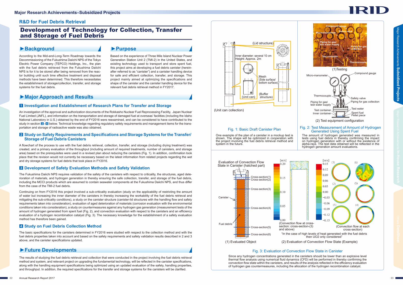
The amount of hydrogen generated was measured in tests using fuel debris in thereby confirming the impact on hydrogen generation with or without the existence of alpha-rays. The test data obtained will be reflected in the hydrogen generation amount evaluations.
One example of the plan of a canister in a mockup test is shown. The shape will be optimized in cooperation with the project involving the fuel debris retrieval method and system in the future.
Since any hydrogen concentrations generated in the canisters should be lower than an explosive level thermal flow analysis using numerical fluid dynamics (CFD) will be performed in thereby confirming the convection flow state within the canisters, and results of the analysis reflected in the efficiency evaluation of hydrogen gas countermeasures, including the allocation of the hydrogen recombination catalyst.
Compound gauge
Compound gauge
Safety valve
Test waterSpent fuelPellet piece
Micro-manometer Safety valve
Test container
Thermocouple
Piping for gas collection
Piping for gas/test water supply
Micro-manometer
Test containerInner container
Evaluation of Convection Flow State in Canister (hatched part)
Canister
Fuel debris(Convection flow at each
cross-section)
(Convection flow at cross-section: cross-section-(3) and above)
“In the case of high levels of heat generated with the fuel debris then UO2 only considered”
Cross-section(6)
Cross-section(5)
Cross-section(4)
Cross-section(3)
Cross-section(2)Cross-section(1)
(1)Testing
(1) Evaluated Object
(2) Test equipment configuration
(2) Evaluation of Convection Flow State (Example)
Thermocouple
Piping for gas collection
(Lid structure)
(Buffer structure)(Unit can)
(Unit can collection)
Mesh (Side surface/bottom surface)
Inner diameter: several 10 cmHeight: Approx. 2m
Piping for gas/test water supply
Development of Technology for Collection, Transfer and Storage of Fuel Debris
R&D for Fuel Debris Retrieval
►Background ►PurposeAccording to the Mid-and-Long-Term Roadmap towards the Decommissioning of the Fukushima Daiichi NPS of the Tokyo Electric Power Company (TEPCO) Holdings, Inc., the plan with the fuel debris retrieved from the Fukushima Daiichi NPS is for it to be stored after being removed from the reac-tor building until such time effective treatment and disposal methods have been determined. This therefore necessitates the establishment of storage/collection, transfer, and storage systems for the fuel debris.
Based on the experience of Three Mile Island Nuclear Power Generation Station Unit 2 (TMI-2) in the United States, and existing technology used to transport and store spent fuel, this project aims at developing a fuel debris canister (herein-after referred to as “canister”) and a canister handling device for safe and efficient collection, transfer, and storage. This project mainly aimed at optimizing the specifications and shape of the canister and the canister handling device for the relevant fuel debris retrieval method in FY2017.
Investigation and Establishment of Research Plans for Transfer and Storage
Development of Safety Evaluation Methods and Safety Validation
Study on Fuel Debris Collection Method
Study on Safety Requirements and Specifications and Storage Systems for the Transfer/Storage of Fuel Debris Canisters
►Major Approach and Results
The Fukushima Daiichi NPS requires validation of the safety of the canisters with respect to criticality, the structures, aged dete-rioration of materials, and hydrogen generation in thereby ensuring the safe collection, transfer, and storage of the fuel debris, including the MCCI products which are assumed to contain seawater components at the Fukushima Daiichi NPS, and thus differ from the case of the TMI-2 fuel debris.
Continuing on from FY2016 this project involved a sub-criticality evaluation (study on the applicability of restricting the amount of water but increasing the inner diameter of the canisters in thereby increasing the workability of the fuel debris retrieval and mitigating the sub-criticality conditions), a study on the canister structure (canister-lid structures with the handling flow and safety requirements taken into consideration), evaluation of aged deterioration of materials (corrosion evaluation with the environmental conditions taken into consideration), a study on countermeasures against any hydrogen gas generation (measurement tests of the amount of hydrogen generated from spent fuel (Fig. 2), and convection evaluation with respect to the canisters and an efficiency evaluation of a hydrogen recombination catalyst (Fig. 3). The necessary knowledge for the establishment of a safety evaluation method has therefore been gained.
The basic specifications for the canisters determined in FY2016 were studied with respect to the collection method and with the fuel debris properties taken into account and based on the safety requirements and safety validation results described in 2 and 3 above, and the canister specifications updated.
A flowchart of the process to use with the fuel debris retrieval, collection, transfer, and storage (including drying treatment) was created, and a primary evaluation of the throughput (including amount of required treatments, number of canisters, and storage area) based on the prerequisites were used in a revised plan about reducing the canisters (Fig. 1). In addition, confirmation took place that the revision would not currently be necessary based on the latest information from related projects regarding the wet and dry storage systems for fuel debris that took place in FY2016.
An investigation of the approval and authorization documents of the Rokkasho Nuclear Fuel Reprocessing Facility, Japan Nuclear Fuel Limited (JNFL), and information on the transportation and storage of damaged fuel at overseas’ facilities (including the Idaho National Laboratory in U.S.) obtained by the end of FY2016 were reexamined, and can be considered to have contributed to the study in section – below. Technical knowledge regarding regulatory safety requirements and management items for the trans-portation and storage of radioactive waste was also obtained.
►Future DevelopmentsThe results of studying the fuel debris retrieval and collection that were conducted in the project involving the fuel debris retrieval method and system, and relevant project on upgrading the fundamental technology, will be reflected in the canister specifications, along with the handling equipment specifications being optimized using an updated evaluation of the safety, handling properties, and throughput. In addition, the required specifications for the transfer and storage systems for the canisters will be clarified.

2524 Annual Research Report 2017
Major Research Achievements–Subsidized Projects
Major R
esearch Achievem
ents Subsidized ProjectsM
ajor Research A
chievements In-H
ouse Research
Others D
ataSheet
Fig. 3: Detection Performance with Single Neutron Location
Fig. 4: Detection Performance with Gamma-Ray/Neutron-Ray Combined Locations
Fig. 1: Layout of Performance Validation Test Fig. 2: Detection Performance at Single Gamma-ray Location
Recording device (PC)
Gamma-ray source
Processor
HUB
Neutron-ray source
Sensor part expansion
• Straight line shows regression • Error bar shows detection
range of multiple elements
Moderating material
(Co-60)
(Pu-Be or Cf-252)
CMOS (Number of elements differ in each test. 2, 4 and 6)
Number of elements
Number of elements
Tota
l of g
ray
valu
e fo
r eac
h pi
xel
Neu
tron
coun
t (cp
s)
Gamma-ray dose rate (Gy/h)
302520151050
1
0.1
0.01
0.001
1000
100
10
1
0.1
0.01
0
0.1 0.1
105 Gy/h
772 Gy/h983 Gy/h
1 110 10100 1001000 1000
200 400 600 800 1000
Test conditions • Neutron flux 0n/(cm2·s) • Gamma-ray dose rate:
63–983 Gy/h • Irradiation time: 5min.
Max. total pixelsapprox. 31% of strength
Neutron flux (n/(cm2/s)) Neutron flux (n/(cm2/s))
Neu
tron
coun
t (cp
)
Development of Small Neutron Detectors
R&D for Fuel Debris Retrieval
►Background ►PurposeRetrieving the fuel debris necessitates identifying the posi-tion and amount. The neutron measurement method, which makes measurements using the neutrons generated from the spontaneous fission of elements in the fuel debris, is one of the methods for retrieving the fuel debris. However, existing sensors may not be capable of being used due to the dimen-sional restrictions, thus making a smaller censor necessary.
The weak neutrons need to be measured under the high-dose gamma-rays by accessing the vicinity of the fuel debris with a detector in order to actually detect the fuel debris. However, the route used to access the vicinity of the fuel debris is rather narrow, thereby making a smaller sensor necessary. This project aims at developing a small neutron detector that will satisfy that requirement.
Specifying the neutron detection technology applicable to the fuel debris retrieval at the Fukushima Daiichi NPS and element test survey results of its feasibility (Phase-1)
Other Phase-1 Studies
Performance Validation of Element Technology
►Major Approach and Results
Phase-1 involves the applicability to Fukushima Daiichi being evaluated after element tests.�In order to study the capabilities of the feasible neutron detector and the specifications the results of a performance validation via element tests were clarified, and the capabilities and specifications of the neutron detector in actual use considered.
�With respect to the conceptual design of the neutron detector the use of a neutron measurement system was assumed in an investigation of the outside of the Unit 1 pedestal (a method to where a sensor descends from the grating on the 1st floor), and a concept neutron detector designed.
�The study involved the establishment of a neutron detector development plan, and discussing the relevant schedule up to the production period toward practical application, the cost, the delivery due date, and the handling of the developed detec-tor (Availability of measurements by a plant operator and the necessity of preliminary training, etc.) Practical application was thereby determined.
The test production of a small neutron detector was commenced upon based on the results of Phase-1.�The sensor design and production were commenced upon; and more specifically, the design of a CMOS sensor, the sensor
installation, a study on the performance validation method using a single CMOS sensor, and the design of peripheral equipment and software.
�The test production and evaluation of the sensor unit were commenced upon with respect to the basic design of the sensor unit, the design of the peripheral equipment, and the planning of the performance evaluation tests.
Element test of a CMOS semiconductor type neutron detector was performed and its performance verified (Fig. 1).�Basic property tests were conducted at a single neutron location in confirming that the sensor was capable of obtaining the neutron flux from the neutron count (Fig. 3). In addition, confirmation also took place that the signal strength obtained against the gamma-rays was linear in the single gamma-ray location (Fig. 2).
�The detection performance under the combined irradiated environment of gamma-rays and neutron-rays was confirmed in identifying the cluster pattern using alpha-rays derived from neutrons in the combined location (Fig. 4).
�The results of the radiation resistance evaluations confirmed that there would be no incorrect detection of neutrons up to the cumulative gamma-ray dose, or degree of 1000Gy. In addition, the results of irradiating a single neutron revealed no remarkable increase in the count, even with irradiation of more than 6.5e+6n/(cm2·s)·s.
�The long distance signal transmission properties confirmed that transmission could take place over more than 50m because the neutron count with a 50m long cable was almost the same as that of a 16m cable length.
�In confirming the effect of the reaction layer neutrons were irradiated at the sensor without a 6Li coating, which is the reactive layer of the sensor. The results confirmed that neutrons could basically not be detected practically if there were no reaction layer.
�The results of measuring the neutron flux with the direction of the sensor normal line and neutron generation in evaluating the directional dependency revealed that the angle of the sensor face provided no significant change up to 45 degrees. However, the neutron flux did decrease beyond that.
►Future DevelopmentsFollowing Phase-2, the production of the sensor as well as the sensor unit and performance evaluations will be conducted in the completion of a small neutron detector by the end of the second quarter of FY2018. More specifically, a survey of an application in which a smaller neutron detector when compared with the existing one, and the required specifications determined. After com-pletion of this project the decommissioning activities at Fukushima Daiichi NPS, including a detailed investigation inside the PCVs and monitoring during the fuel debris retrieval etc., will be substantiated for application in the project.

2726 Annual Research Report 2017
Major Research Achievements–Subsidized Projects
Major R
esearch Achievem
ents Subsidized ProjectsM
ajor Research A
chievements In-H
ouse Research
Others D
ataSheet
Sections Major shape change Unit 1 Unit 2 Unit 3
Reactor core
• Submerging of remnant fuel
Minimal(almost no
remnant fuel)
Medium(Fuel may remain
in/around the reactor core.)
Low(Fuel may remain
in periphery)
RPV lower part
• Submerging of debris
• State variation during retrieval
Submerging: LowRetrieval: Minimal(Small remnants)
Submerging: MediumRetrieval: Low(Large remnant,
exposure)
Submerging: MediumRetrieval: Low(Large remnant,
exposure)
CRD Housing
• Submerging of attached debris
Low ~ Minimal(attached shape
and amount)
Low ~ Minimal(attached shape
and amount)
Low ~ Minimal(attached shape
and amount)
PCV bottom
part
• Submerging of exposed debris
• State variation during retrieval (including curling)
Submerging: LowRetrieval: Low(large residue,
small exposure)
Submerging: MediumRetrieval: Low(Large remnant, large exposure)
Submerging: LowRetrieval: Low(Large remnant, small exposure)
Table 1: Degree of Importance for Criticality Control by Units and Sections (relative evaluation)
Fig. 3: Overview of Criticality Monitoring
Fig. 2: Criticality Approach Test at Kyoto University Criticality Assembly (KUCA) Laboratory Device
Fig. 1: Exposure Evaluation ModelThe concrete deployment of criticality prevention and criticality approach detection technologies are being studied depending on their degree of importance in controlling criticality.
Localized criticality will be monitored by the neutron detector and entire PCV monitored by the gas control system (Gamma-ray monitoring of rare gases).
KUCA can be used with variable amounts of fuel and moderator according to the purpose of the test and to simulate various fuel debris conditions and hence was used in the criticality approach detection and nuclear characteristic tests.
These models are used in studying the specifications of the safety measure facilities and are reflected in designs in thereby avoiding any excessive exposure in the case of criticality occurring
Exposure via leakage
Submersion method Partial-submersion method
Direct lineSky shine
Grand shine
Measurement range of existing radiation monitor
Gamma-ray energy(keV)
Kr-88 detection is available in high energy region.
Kr-88
Kr-88Kr-85
Cs-137Cs-134
Kr-87
Kr-87
Xe-135
Absorption material that spreads over the surface of rock shape simulated debris with unevenness in the water
Absorption material flowing down to granular simulated debris in water
Public
Worker on operating floor
Gas control system
Exposure via environmental
releaseA worker
outside the building
“Appearance of KUCA Test”
“Image of Gamma-Ray Measurements by Gas Control System”
B4C sintered metal material
B/Gd containing glass
Granulated cement/Gd2O3 powder (Left; before hardening: Right; after hardening)
Granulated liquid glass/Gd2O3 powder (after hardening)
Underwater hardening resin/Gd2O3 powder (Left; before hardening: Right; after hardening)
Glass material image after formation
Gd2O3 particles
“Example Test Reactor Core”
“B-10 Neutron Detector”
“Image of Neutron Signals”
Reflector cell Fuel assembly cell
Control rod cell
Neutron detector
Gas control system
For local monitoring
For overall monitoring
Rare gases, etc.
Rare gas
Rare gas
Gas chamber Shield (lead)
Ge detector
Neutron detector
Num
ber o
f cou
nts
Fig. 5: Appearance of Insoluble Neutron Absorption Material (candidate material)
Fig. 4: Result of Gamma-Ray Measurement Tests by Gas Control System
SolidLiquid→Solid
(Solidified material)
Fig. 6: Example of Workability Verification Test of Water Glass Type Absorption Material
Development of Technology for Criticality Control Methods
R&D for Fuel Debris Retrieval
►Background ►PurposeThe assumption is that the fuel debris has not currently reached criticality. The development of a criticality control method is underway in thereby ensuring criticality can be pre-vented in which the shape of the fuel debris and the change in the amount of water are estimated for during the fuel debris retrieval work in the future, as well as the termination of any criticality in a safe manner, even if it does occur.
An impact evaluation method for use with criticality shall be established via the formulation of criticality scenarios and by developing a behavior evaluation method during a criticality situation. Moreover, criticality prevention technology using neutron-absorbing material with soluble/insoluble properties and criticality monitoring technology, including technology for criticality approach detection and recriticality detection, will be developed and their technical feasibility confirmed.
Establishment of Criticality Evaluation Method
Development of Criticality Approach Monitoring Method
Development of Recriticality Detection Technology
Development of Criticality Prevention Technology
►Major Approach and Results
The development of subcriticality measurement technology that is based on neutron measurements has been promoted. Operational verification tests of the B-10 neutron detector in a radiation environment were performed in FY2016 in order to confirm its feasibility with the site environment, with the discrimination of neutron-rays and gamma-rays confirming their feasibility when used with appropriate shielding. A reactor core, which simulates the various fuel debris conditions, was configured at the Kyoto University Critical Assembly (KUCA) laboratory in FY2017, and the degree of subcriticality evaluated using the reactor noise method then confirmed the estimate from the neutron signals obtained (Fig. 2). The feasibility of the criticality approach monitoring technology was thus confirmed by the neutron measurements.
The gas control system used to monitor slight amounts of FP gas concentrations present in the Primary Containment Vessel (PCV) (Fig. 3) was improved for use in detecting any recriticality in the early stages, and Kr-88 detection technology, which can be used for prompt responses during criticality in addition to the Xe-135 technology that is currently being used in monitoring, is being developed.This technology is based on gamma-ray measurements using a germanium (Ge) detector and the gamma-ray energy measure-ment range was increased to 3MeV in order to be capable of collecting gamma-ray data at the Fukushima Daiichi Unit 1 which is equipped with a Ge detector. The results confirmed that the objective nuclides had no impact in the high gamma-ray energy regions and the peak of Kr-88 (Fig. 4). This study confirmed the possibility of early criticality detection using the enhanced gas control system.
Neutron absorbing materials for use in preventing criticality from occurring that are of the water soluble/non-soluble type have been developed.With respect to the non-soluble absorbent material nuclear characteristic verification tests at the KUCA, dissolution tests with long-term exposure, and performance workability tests (Fig. 6) took place using candidate materials selected by their fundamental physical properties and radiation resistance performance tests (Fig. 5), and a prospect absorbent material candidate obtained.In addition, the soluble neutron absorbent material (sodium pentaborate) confirmed the required boron concentration estimate to be about 6,000ppm as a conservative assumption. This estimate exceeds the concentration proven to exist at the power genera-tion reactor and hence a nuclear characteristic verification test was performed at the KUCA in thereby confirming that the nuclear properties could be evaluated with the same accuracy as previous. Moreover, the basic specifications of the boron concentration maintenance facility were examined. Herewith, the prospect of boron concentration evaluations and the technical feasibility of the necessary facilities, including the concentration maintenance facility, were obtained.
Based on the estimated information on the fuel debris distributions obtained from the results of evaluations and investigations inside the reactor, and muon measurements, the relative importance of criticality control while the fuel debris is being retrieved from each unit was evaluated (Table 1). The results will be used in the studying the concrete deployment of technologies for use in both monitoring and preventing any criticality from occurring.A behavior evaluation method during criticality via an exposure evaluation model was developed, and an evaluation method that could be used to evaluate the behavior from the occurrence of criticality through to its termination and the impact of any exposure to the public and workers established (Fig. 1). They will be utilized in studying the procedures to use to mitigate any impact in the case criticality occurs and safety measures to use at facilities in the future.
►Future DevelopmentsProspective establishment of a criticality evaluation method for use with the fuel debris retrieval and feasible criticality control technology were obtained, and the results will be utilized in studying the optimal practical implementation of a fuel debris retrieval device and relevant systems, and thus ensuring greater safety in the future.

2928 Annual Research Report 2017
Major Research Achievements–Subsidized Projects
Reactor Building
PCV RPV
Reactorshielding
wall
Foundation of main reactor structure
Elasticity/elastic-plastic properties (image)
Load
Displacement
Air lock forworkers
Vent pipe
RPV pedestal
PCV stabilizerRPV
stabilizer
Analysis model/conditions Basic test data
Evaluation/countermeasure study
Seismic response analysis (building – equipment coupled)
Time history elasticity/elastic-plastic analysis (RPV pedestal, S/C support column)
• Thermal degradation at the time of the accident, assumed erosion
• Long-term erosion prediction after the accident
745mm
1500mm
z
y
x
Major R
esearch Achievem
ents Subsidized ProjectsM
ajor Research A
chievements In-H
ouse Research
Others D
ataSheet
Fig. 1: Overall Development Flow of Seismic Analysis Method
Fig. 3: Vent Pipe–S/C System Coupled Analysis Conditions and Time History Seismic Response Analysis Model (Unit 2–3)
Fig. 2: Reactor Building/Large Equipment System Coupled Model
Fig. 4: Detailed Analysis Model of Vent Pipe for Elastic-Plastic Analysis and S/C System (Unit 2–3)
Fig. 5: Development of Seismic Evaluation Method for Pedestal due to Debris Erosion
Vent pipeVent pipe
Vent header Downcomer
Downcomer burial height
Vent header
Dry well
Vent pipe
Downcomer
Detailed FEM analysis model of S/C system
Cross-sectional drawing
CRD opening
CRD opening
CRD opening
CRD opening
FEM analysis model of 1F-Unit 1 Modeling of debris erosion parts
Lower Access Opening Part
�Internal only deficiency (element reduction)
�Deficiency range, inside/outside
(free boundary)
Central opening
Detailed FEM analysis model of vent system
1/2 sector solid component model
Concrete injection conditions in S/C with water stopped in
downcomer assumption
Bonds
Vent header
S/C
Downcomer
Column support
Suppression Chamber
Seismic resistance support
Column support
Seismic resistance support
External
Internal
Development of Seismic Resistance and Impact Evaluation Methods for RPV / PCV
R&D for Fuel Debris Retrieval
►Background ►PurposeDue to the severe events caused by the Great East Japan Earthquake the Reactor Pressure Vessel (RPV) and Primary Containment Vessel (PCV) at the Fukushima Daiichi NPS were affected by high temperatures, seawater, and falling fuel debris and thus concerns about the material further dete-riorating. Measures to maintain the structural integrity of the PCV/RPV are thus required over the long term that retrieving the fuel debris from the reactor core will take.
This project aims at clarifying what important equipment in RPVs/PCVs got damaged in the event of the large-scale earthquake and the spread of the impact on the water levels in the PCVs that can be assumed during the debris retrieval work and installation of important equipment in the building. Countermeasures to prevent or suppress that impact will be developed and its efficacy confirmed through seismic assessments.
Establishment of Safety Scenarios during Large-Scale Earthquakes
Upgrading of Safety Scenarios
Development of Seismic Resistance/Impact Evaluation Methods in Establishing Safety Scenarios
►Major Approach and Results
The development of seismic resistance and impact evaluation methods has been promoted based on the flow and feedback shown in Fig. 1.
Development of Seismic Resistance/Impact Evaluation Methods for Suppression Chamber (S/C) Support ColumnIn order to evaluate seismic resistance while stopping the water in the downcomer by injecting filling into the S/C coupled analy-sis model (Fig. 3) connected with the vent pipes and the S/C systems in Units 2–3 was created and time-based history seismic response elastic analysis performed. The important evaluation parts: the column support, the seismic resistance support, and the vent header were all evaluated via elastic analysis as well as a detailed FEM model created in confirming the downcomer burial conditions.
Development of Seismic Resistance/Impact Evaluation Methods for PedestalsThe data obtained uses assumptions about the pedestal temperature history and its distribution in the development of the follow-ing evaluation method for erosion impact evaluation from the fuel debris and material data.
• Simplified evaluation where the amount of erosion is a parameter and the detailed evaluation method uses the 3D FEM elastic analysis model shown in Fig. 5.
• The earthquake response impact evaluation method uses the building/large equipment system coupled model (Fig. 2) in which the stiffness degradation is a parameter that assumes the erosion in the RPV pedestal.
• High temperature erosion and strength degradation amounts for use in assuming the strength degradation of reinforcing steel in concrete.
Safety scenarios (safety functions that maintain or can be used in responding to restoration after accidents have occurred) were established based on countermeasures for the facility which will be performed before the start of any fuel debris retrieval and as a swift preparatory response to the potential risk resulting from any damage to major equipment due to a large-scale earthquake.
A confirmation method that includes analysis and tests was studied for the upgrading of the evaluation method above . The following detailed analysis and material tests were conducted.
• Evaluation via time history elastic seismic response analysis of the S/C support column in Unit 1.
• Acquisition of PCV material test data through taking the temperature history at the time of the accident into consideration.
►Future DevelopmentsThe safety scenarios will be reviewed according to the progress status of related projects (fuel debris retrieval system, PCV inter-nal survey, etc.).

3130 Annual Research Report 2017
Major Research Achievements–Subsidized Projects
Major R
esearch Achievem
ents Subsidized ProjectsM
ajor Research A
chievements In-H
ouse Research
Others D
ataSheet
Actual collected sludge (10mL vial container)
The condition of sludge at the bottom of storage layer-D (Yellow)
Overview of investigation inside storage layer-D (Cross-section)
Fig. 1: Correlation of Sr-90 and Cs-137 in Rubble in R/B
Fig. 2: Examples of Analysis Value Distribution (Upper Drawing) and Inventory Assumption (Lower Drawing)
Radioactive concentration of Cs-137(Bq/g)
(Outlined characters show lower detection limits)
Aboveground floor: Decontaminant (AREVA) installation area Worker
Ground levelStorage layer-D
Ground water level
West – East
Underwater camera
Acceptance of wide
variety of waste
Increasing the capacity of disposal
facility
Correspondence to risk
uncertainties
Example, Large container of mixed waste Example, Large vault Example, Human
entrance prohibition
Solid content
Approx. 40cm
B1F
1F
B2F
Outer w
all
Rad
ioac
tive
conc
entra
tion
of
Sr-
90(B
q/g)
Unit 1103
3.0E-01
2.5E-01
2.0E-01
1.5E-01
1.0E-01
5.0E-02
0.0E+00
1.E+11
1.E+09
1.E+07
1.E+05
1.E+03
1.E+010 0.05 0.150.1 0.2
Pu-2385%ile
95%ileAnalysis results from actual waste (Concentration)
Explanatory note
medlanaverage
20181614121086420
3.16.E
-04
1.00.E
-04
3.16.E
-03
1.00.E
-02
3.16.E
-02
1.00.E
-01
101
10-1
10-3
10-2 10-4
100 102 104 106
Unit 2Unit 3
Data frequency
Transport ratio (Compared to Cs-137)
Pro
babi
lity
dens
ity
Dat
a fre
quen
cy
Nuc
lide
conc
entra
tion
(Bqt
)
Probability density
Probability density (Normal logarithmic
distribution)
Fig. 5: Detailed Survey of Overseas Repositories
Fig. 3: Glass Solidification Tests Using Simulated Waste
R&D for Treatment and Disposal of Radioactive Waste
R&D for Treatment and Disposal of Solid Radioactive Waste
►Background ►PurposeThe fuel debris will be retrieved from the Fukushima Daiichi NPS in addition to the debris etc. that has already been stored and hence a large amount of waste can be estimated to be generated in the future. Because of this situation, meth-ods to store, treat, and dispose of the waste in the implemen-tation of the project will need to be developed in parallel with their characterization.
This project aims at developing technology for the safe treat-ment and disposal of the solid waste generated in the acci-dent by integrating the results of Research and Development (R&D) resulting from characterization of an inventory evalu-ation based on waste analysis and a study of solidification technology, the stabilization of secondary waste generated from the water treatment, and concepts of the treatment and safety evaluation method used.
Characterization
Study of Concepts of Disposal Applicable to Solid Waste and Safety Evaluation Method
Integration of R&D Results
Preliminary Management
►Major Approach and Results
Applicability Evaluation of In-Drum Type Glass Solidification TechnologyAs part of the stabilization technology required for the preliminary management of the secondary waste generated in the water treatment in-drum type glass solidification technology was focused upon from the aspect of contamination dispersion prevention and equipment size. The solidification results from simultaneous melting with zeolite being used for the contaminated water treat-ment and other simulated waste from the secondary waste generated by the water treatment (Fig. 3). Basic data, which includes chemical analysis and a leaching test from the solidification, was collected, and the composition and conditions of the solidification thus provided.
Study on Decontaminant Device Sludge Stabilization (including sample collection)The internal conditions of reservoir tank D in the main process building where sludge generated from the decontaminant device has been stored were surveyed in collecting some actual sludge (Fig. 4). An underwater camera revealed the thickness of the accumulated sludge layer to be approximately 40cm, and hence its volume was estimated to be 37m3. In addition, basic data related to fluidity was obtained using simulated sludge in the study on the sludge retrieval.
Analysis of the rubble, contaminated water, and secondary waste generated from the water treatment continues to takes place in amassing data. In addition, the concentration of various nuclides is compared to Cs-137 in thus investigating contamination behavior using the analysis data obtained so far. The results revealed that the Sr-90 and Cs-137 concentrations indicate a cor-relation with the rubble samples in the reactor building, regardless of the unit (Fig. 1), with the same behavior being observed with the other nuclides. Furthermore, the contamination frequency distribution of radioactive nuclides indicates the normal logarithmic distribution used with the amount of radioactivity (inventory), including the radioactive waste, and which is being estimated (Fig. 2).
A detailed survey (Fig.5) of overseas repositories: the U.K. Low Level Radioactive Waste Repository (LLWR), the Swedish Final Repository for low and intermediate level short-life radioactive waste (SFR), the U.S. Waste Control Specialist (WCS) for low level radioactive waste disposal, among others, was conducted in the development of information to use with the concepts of applicable solid waste disposal and safety evaluation method, as well as the applicability to the solid waste at the Fukushima Daiichi NPS being studied based on various case scenarios and with domestic disposal cases and the characterization of the solid waste taken into consideration.
The waste stream was reflected in the latest results obtained from existing research and the establishment of a method of ensur-ing consistency in the progress made, results, and remaining issues commenced upon.
►Future DevelopmentsAnalysis will be continued to be reflected in improving the inventory estimation model as well as tests related to the stabilization of the secondary waste generated by the water treatment. In addition, a detailed survey of overseas’ disposal concepts and the evaluation method, and evidence and background will continue, and applicability to the solid waste treatment at the Fukushima Daiichi NPS reviewed. The above results will then be examined with respect to the waste stream.
Fig. 4: Investigation inside Main Process Building Storage Layer-D and Collection of Sludge from Decontamination Device
• Production of glass solidification of secondary waste generated in the simulated water disposal (mixed zeolite, sludge from the decontamination device, and additives such as B2O3)

3332 Annual Research Report 2017
Major Research Achievements–In-House Research Others–DataSheet
Major R
esearch Achievem
ents Subsidized ProjectsM
ajor Research A
chievements In-H
ouse Research
Others D
ataSheet
►Background and Purpose
►Major Approach and Results
►Major Approach and Results
►Background and Purpose
No. Presented at / by Date Details
1 The 50th JAIF Annual Convention 2017 Apr. 11, 2017 Robotics Technology Utilization
2 Special Lecture on Nuclear Reactor Decommissioning, Tokyo Institute of Technology Apr. 21, 2017 Current State of Fukushima Daiichi NPS and Road to Reactor
Decommissioning
3 2017 International Congress on Advances in Nuclear Power Plants (ICAPP 2017) Apr. 26 – 28, 2017 Robot Exhibition
Lecture: Overview of IRID R&D - Focusing on Debris Investigation
4 Societe Francaise d’Energie Nucleaire, Les accidents graves (French Nuclear Society, The severe accidents) May 10, 2017 Fukushima Daiichi: Clarification of the accident progression,
current plant status and R&D programs in Japan
5 Electrical Review 2017, Summer Special Issue May 12, 2017Development of Inside Survey Equipment for Nuclear Reactor Containment Vessel– Shape Variation Type Robot [PMORPH] –
6 [The contemporary Science and Technology Giant Seminar “The Inspiration of Knowledge”], Kyoto University May 17, 2017 Working for Radioactivity
7 NSC2017 (Chernobyl Workshop) May 18, 2017 Fuel debris and MCCI product characterization for Fukushima Daiichi NPS
8 The 42nd Task Team Meeting for Decommissioning / Polluted Water Control / Secretariat Conference May 25, 2017 Analysis of Solid Waste Sample, Fukushima Daiichi NPS
(Accomplishment report to the present situation), etc. 2 cases
9 Robotics Consortium, Shibaura Institute of Technology May 26, 2017 Future of Decommissioning and Robotics Technology
10 National Institutes for Quantum and Radiological Science and Technology (QST) Jun. 1, 2017
Impact Evaluation of Gamma-Ray Exposure Exerting the Local Erosion of Carbon Steel in the Diluted Artificial Seawater in which Rust-Proof Agent is Added, etc. 2 cases
11 NPO Japan Association for Automation Advancement General Meeting Jun. 3, 2017 Future of Decommissioning and Robotics Technology
12Professional Meeting for Basic Study Related to the Reliability Keeping of Containment Vessel / Building and Waste Disposal for Decommissioning Action and Core Human Resource Cultivation Program
Jun. 12, 2017 Proof Strength Evaluation of Severe Accident Experienced Reinforced Concrete Structure
13 JOURNAL OF NUCLEAR SCIENCE AND TECHNOLOGY Jun. 12, 2017 Development of the model for advection and diffusion of eroded concrete into debris in molten core-concrete interactions
14 The 30th Regular Seminar of [Water Chemistry Committee], Atomic Energy Society of Japan Jun. 23, 2017 Impact Evaluation on Rust-Proof Agent Exerting the Local Erosion
of Carbon Steel in the Diluted Artificial Seawater
15 FY2017 Summer Special Issue, [Electrical Review] Jun. 30, 2017Front Line of Disaster Corresponding Robot– Prospect at Flammable Gas Generation and Approach to the Firefighting Activity at Large-Scale Fire –
16 Knowledge Innovation Research Group Meeting, Knowledge Management Society of Japan Jun. 30, 2017 Overview of Activities of International Research Institute for
Nuclear Decommissioning
17 ACTINIDES 2017, SendaiProgress in Nuclear Science and Technology Jul. 2017 Characterization of the VULCANO test products for fue debris
removal from the Fukushima Daiichi Nuclear Power Plant
18 International Trade Fair [1 FPEX 2017] Hosted by Japan Fluid Power Association Jul. 2017
Water moves machine!Safety of food! Safety of person! Safety of town! Safety of Country!
19 The Second International Forum of the Fukushima Daiichi Decommissioning Jul. 2 – 3, 2017 Estimation of Situation inside the Reactor Core and PCV
Fukushima Daiichi NPS
20 International Conference Actinides 2017; and Progress in Nuclear Science and Engineering Jul. 10, 2017 Chemical state analysis of simulated corium debris by EXAFS,
etc. 2 cases
21 The 16th Materials Division Summer Seminar, 2017; Atomic Energy Society of Japan July 12, 2017 Development of Technology for Corrosion Control of RPV/ PCV
in 1F
22 The 14th Academic Conference, Japan Society of Maintenology Aug. 2, 2017 Development and Verification of Investigation Device inside PCV– Basement Survey by Shape Variation Type Robot [PMORPH] –
23 IRID Symposium 2017 in Iwaki Aug. 3, 2017 Conceptual Description of Element Technology for upgrading Fundamental Technology
24 [The 14th Nuclear Power Technology Summer Seminar], Nuclear Power Group Meeting Aug. 4, 2017 Approach to Domestic and Foreign Nuclear Power
25 Technical Information Center Seminar Aug. 22, 2017 The Latest Technique Development of Nuclear Power Plant Robot toward Decommissioning/ Convergence Support
26 Study on Characterization of Fuel Debris and Human Resource Cultivation Conference (ConFDeC2017) Sep. 6, 2017 Current Status of Fukushima Daiichi NPS and R&D for Fuel
Debris Retrieval
27
Creative Human Resource Cultivation Program through Basic Study on Decommissioning– Transdisciplinary Challenge from Fukushima Using Inter-College Network –FY2017 Section Meeting and the 1st Research Report Meeting
Sep. 6, 2017 R&D Status of International Research Institute for Nuclear Decommissioning
Major Research Results in FY2017Measurement and Evaluation of Fuel Debris Distribution inside Reactor at Fukushima Daiichi NPS Unit 3
Development of Remote Collaboration Motion Control System
Fig. 1: Image of Muon Measurements Penetrating Reactor Building (East-West Cross Sectional Drawing)
Fig. 3: Evaluation of Distribution of Substance Quantity (density length) via Simulation (Case of fuel debris being present at the reactor core and at the bottom of the reactor)
Fig. 2: Image of Muon Measurements Penetrating Reactor Building (South-North Cross Sectional Drawing)
Fig. 4: Evaluation of Distribution of Substance Quantity (density length) using Muon Measurements
(As of September 8, 2017)
Reactor building
Turbine building
West East
NorthSouth
Measurement device
Measurement device
Building wall (Major steam isolation valve room) Building wall
(Major steam isolation valve room)RPV RPV
Reactor core region
Reactor core region
High place on mountain side
PCV peripheral concrete
PCV peripheral concrete
Spent Fuel Pool
Spent Fuel Pool
Estimated position of reactor core
Spent Fuel Pool
(SFP)
aa
Photo 1: Decontamination Device for Upper Floors
Photo 2: Testing of This Research
As an approach to identifying the conditions inside the reactor and toward retrieving the fuel debris muon transmission measure-ments* have been made in thereby identifying the distribution of substance quantities in the Reactor Pressure Vessel (RPV) using the penetration rate of muons that could penetrate the reactor as a method of obtaining information on the fuel debris distribution at the Fukushima Daiichi NPS Units. The same measurements and evaluations were conducted for Unit 3.* The measurements were developed using technology of the High Energy Accelerator Research Organization
Measured Results at Unit 3
Operational Test of Route Tracking
Summary
Evaluation Results of Unit 3
Future Developments
Muon measurements, which can penetrate the reactor build-ing, confirmed major structures such as the shielding concrete of the Primary Containment Vessel (PCV) peripheral, the spent fuel pool, and the reactor building wall.
The results of the evaluation will be utilized in the approach used with the fuel debris retrieval in the future in addition to other expertise obtained from investigations made inside the PCV.
The results of evaluating the fuel debris distribution in the RPV through measurements made with the muon penetration method are as follows. No mass of fuel debris is present in the original reactor core
region. Fuel debris may remain at the bottom of the RPV, although
uncertain.
The dry ice blast decontamination device for high places and decontamination device for the upper floors that were developed using the FY2013 supplementary budget consist of multiple crawlers, with each of the carts being operated by operators.This research aims at developing the technology of an auto-matic tracking vehicle that following carts can automatically use with respect to the route to take in order to reduce the number of required operators.
Testing of the route tracking on a test course that was a simu-lation of the reactor building 1st floor (straight, narrow areas, avoiding obstacles, cornering, and searching for the lead cart) confirmed that the route tracking operation had no problems.
In the case of use of decommissioning devices that consist of multiple carts on-site a remote collaboration motion control system will be developed in thereby reducing the number of necessary operators.

3534 Annual Research Report 2017
Others–DataSheet
Major R
esearch Achievem
ents Subsidized ProjectsM
ajor Research A
chievements In-H
ouse Research
Others D
ataSheet
No. Presented at / by Date Details
28 Decommissioning Study / Human Resource Cultivation Enhancement Program, FY2017 Summer School, University of Tokyo Sep. 6, 2017 Remote Technology for Decommissioning and its Design
Methodology, etc. 2 cases
29 The 3rd Asian Nuclear Fuel Society Sep. 8, 2017 A study of cesium chemisorption onto surface of Stainless Steel
30 The 35th Japan Robotics Society Sep. 11, 2017 Robotics Technology for Decommissioning and Expectation to Academy, etc. 3 cases
31 2017 Fall Meeting, Atomic Energy Society of Japan Sep. 13, 2017
Filling Water Stop in S/C(1) Overview Related to 1/1 Scale Actual Size Filling Test(2) Relationship between Stiffening Ring Trans-lesion and
Concrete Mix (Mix-A, Mix-B)(3) Placing up State and Finishing State regarding 1/1 Full Scale
Filling Test(4) Concrete Core regarding 1/1 Scale Full Scale Filling Test(5) Water Stopping Performance of Damaged Hole, Quencher
and Strainer regarding 1/1 Full Scale Filling Test
32 2017 Fall Meeting, Atomic Energy Society of Japan Sep. 13, 2017 Development of Fuel Debris Criticality Control Technique (29) and Criticality Control Policy, etc. 12 cases
33 2017 Fall Meeting, Atomic Energy Society of Japan Sep. 13, 2017
Chemical Reaction Evaluation on Cs and Steel Member at Light-Water Reactor Serious Accident(1) Evaluation on Speed of Reaction between Cs and Steel
Member toward Modeling
34 2017 Fall Meeting, Atomic Energy Society of Japan Sep. 13, 2017Development of Housing-Can for Fuel Debris(1) Colledtion/ Transfer/ Storage Techniques for Fuel Debris, etc.
10 cases
35 2017 Fall Meeting, Atomic Energy Society of Japan Sep. 13, 2017
Study on Identifying of Conditions inside Reactor by Severe Accident Analysis Code MAAP(17) Detailed Analysis on the Accident Progression of Fukushima
Daiichi Unit 2 by MAAP, etc. 2 cases
36 2017 Fall Meeting, Atomic Energy Society of Japan Sep. 13, 2017
Development of Poly-Nuclear Species Analytical Method by ICP-QQQ-MSDevelopment of simultaneous measurement for multi isotopes by ICP-QQQ-MS
37 2017 Fall Meeting, Atomic Energy Society of Japan Sep. 13, 2017
Review on the Preprocessing for Dry Type Storage of Retrieved Fuel Debris– Evaluation on the Drying Property Focused on the Shape of Fuel Debris –Pre-treatment of defueling Fuel Debris for drying storage– Evaluation of Drying Characterization focused on form for Fuel Debris –
38 2017 Fall Meeting, Atomic Energy Society of Japan Sep. 13, 2017
Development of Inventory Evaluation Method for Fukushima Daiichi Accident Waste(11) Review on Analytical Estimation Technique for Contamination
State in Nuclear Reactor Building
39 2017 Fall Meeting, Atomic Energy Society of Japan Sep. 13, 2017
Analysis/ Evaluation on Indentification of Conditions inside Reactor Fukushima Daiichi NPS, TEPCO(91) Evaluation on Debris Spreading State by Actual Machine
Sensitivity Analysis for In-Core State Assumption
40 2017 Fall Meeting, Atomic Energy Society of Japan Sep. 13, 2017 Analysis on Inside Temperature Distribution of Fukushima Daiichi Unit 3 by Using CFD Tool
41 2017 Fall Meeting, Atomic Energy Society of Japan Sep. 13, 2017 Development of Compact Dosimeter toward the Inside Survey of PCV
42 2017 Fall Meeting, Atomic Energy Society of Japan Sep. 13, 2017
Development of Water Stop Technique in S/C by Underwater Inseparable Concrete Filling(11) Overview of Filling Property/ Water Stop Property Confirmation
Tests by Inseparable Concrete Using Full Scale S/C Model
43 2017 Fall Meeting, Atomic Energy Society of Japan Sep. 13, 2017Evaluation on Long-Term Integrity of Fuel Assemblies Retrieved from Spent Fuel Pool(4) Evaluation on Fuel Soundness at Wet Type Storage
44 2017 Fall Meeting, Atomic Energy Society of Japan Sep. 13 – 14, 2017 Development of Inside Survey Equipment for PCV [PMORPH]
45 2017 Fall Meeting, Atomic Energy Society of Japan Sep. 14, 2017 Development of Multi Nuclides Analysis Method by ICP-QQQ-MS
46 2017 Fall Meeting, Atomic Energy Society of Japan Sep. 14, 2017Review on Preprocessing for Dry Type Storage of Retrieved Fuel Debris– Evaluation on Dry Property Focusing on the Shape of Fuel Debris –
47 2017 Fall Meeting, Atomic Energy Society of Japan Sep. 15, 2017 Current State of Technical Development by IRID toward the Decommissioning of Fukushima Daiichi NPS
48 The 3rd Strategical Workshop Related to the Decommissioning of Fukushima Daiichi NPS Sep. 16, 2017 Recommendation to the Decommissioning from Perceptions of
Large MCCI Test at CEA
49 6th Asia-Pacific Symposium on Radiochemistry (APSORC17) Sep. 17, 2017 Application of ICP-MS to analytical methods for samples from 1F site at Okuma Analysis and Research Center
50 HOTLAB2017 (Annual Meeting on Hot Laboratories and Remote Handling) Sep. 17 – 19, 2017 International collaborations at JAEA/CLADS toward decommissioning
of Fukushima Daiichi NPS, etc. 4 cases
No. Presented at / by Date Details
51 Decommissioning Technique, Radioactive Waste Management and Nuclear Facility Decommissioning Technology Center Sep. 20, 2017
Current State of R&D for Fuel Debris Retrieval Technique toward the Decommissioning of Fukushima Daiichi NPS– Overview of R&D Approached by International Research Institute for Nuclear Decommissioning (IRID) –
52 [Introduction to Nuclear Decommissioning Engineering/ Special Topics], Intensive Course of Tohoku University Sep. 23, 2017 Deve lopment o f Robot Techn ique Assoc ia ted w i th
Decommissioning Work and State of Site Application
53 Kansai Nuclear Conference[Research Committee on the Upgrading Technique of Atomic Fuel] Oct. 11, 2017 IRID R&D State toward Fuel Debris Retrieval
54 Academic Journal; The Institute of Systems, Control and Information Engineers (ISCIE) Oct. 15, 2017 Introduction to ROS for Control Researchers
55 The 34th Japan-Korea Nuclear Experts Meeting Oct. 16, 2017 Overview of IRID R&D Focusing on Debris Retrievel
56 The 2nd Committee on Decommissioning Ground Engineering, 2017 Oct. 16, 2017 R&D on Treatment and Disposal of Solid Wastes from Fukushima
Daiichi NPS
57 MIT-Tokyo Institute of Technology Innovative Nuclear Event System (MT-INES) Program Oct. 19, 2017 R&D activityes for Fukushima Daiichi Nuclear Power Station
Decommissioning
58 The 64th Materials and Environmental Discussion Session (Japan Society of Corrosion Engineering) Oct. 24, 2017 Criticality Prevention Measures at Fuel Debris Retrieval by Using
Neutron Absorption Material, and Impact on Erosion
59 MIT-Tokyo Tech workshop on Innovative Nuclear Energy Systems (TM-INES) Oct. 27, 2017 Restoration and decommissioning activities for Fukushima Daiichi
Nuclear Power Station by Toshiba
60 2017 IEEE/SICS International Symposium on System Integration (SII 2017) Oct. 30, 2017 Outcome of [Cooperative Movement Control of Multiple Carts]
61 The University of Tokyo-IRID workshop Oct. 30, 2017 Current State and the Issues of R&D toward Fukushima Daiichi Decommissioning, etc. 2 cases
62 The 64th Materials and Environmental Discussion Session, Japan Society of Corrosion Engineering Nov. 8, 2017
Development of RPV/PCV Erosion Suppression Technique for Fukushima Daiichi NPS: About Selection Result and Management Procedures of Rust-Proof Agent, etc. 3 cases
63 Robot Festival Fukushima, 2017 Nov. 9, 2017 State of R&D Approached by IRID[Survey/ Retrieval of Fuel Debris by Robot]
64[Outcome and Issues of Robot Technique] Hosted by Expert Committee of Production and Management Knowledge, The Japan Society for Precision Engineering
Nov. 13, 2017 Decommissioning of Fukushima Daiichi and Robot Technique
65 Vol. 35, Number 9; Japan Robotics Society Nov. 15, 2017 Development of Fuel Debris Shape Measuring Device
66 The 26th Polymer Materials Forum, The Society of Polymer Science, Japan Nov. 16, 2017 Current State of Technical Development by IRID toward the
Decommissioning of Fukushima Daiichi NPS
67 The 10th International Symposium on Nuclear Science and Technology Nov. 23, 2017 Numerical Analysis for Fulushima-Daiichi Unit 2
68[Conference on the Erosion Prediction and Mitigation of Major Components in Fukushima Daiichi NPS], the 4th Fukushima Research Conference FY2017
Nov. 27 – 28, 2017
Preliminary Evaluation of Radiolytic Hydrogen Amount in Fuel Debris Canister(Provisional Calculation of Hydrogen Generation Amount by the Radioactive Degradation in Fuel Debris Containment Can), etc. 4 cases
69 Discussion Session on X-Ray Material Strength, The Society of Material Science, Japan Dec. 1, 2017 Nondestructive Inspection of Imaging by Muon Scattering Method
70 QST Takasaki Science Festival 2017 Dec. 12, 2017Evaluation on Hydrogen Gas Generation Associated with Gamma-Ray Irradiation Targeted at the Cement Solidification Sample of Contaminated Water Treatment Secondary Waste
71 The Society of Instrument and Control EngineersLecture Presentation, Systems Integration Category Dec. 20, 2017 Development of Operation Training System Related to the
Fukushima Daiichi NPS by Using VR
72 Lecture Presentation on the Measures for Decommissioning and Polluting Water Dec. 20, 2017 Survey Robot Technique Development at IRID
73 Decommissioning Technology and Human Resource Cultivation Forum, Tokyo Institute of Technology; 2017 Jan. 10, 2018 Review on Realistic Criticality Risk Evaluation Method
74 Journal of Japan Electrical Manufacturers’ Association [DENKI] Jan. 24, 2018Current R&D State of International Research Institute for Nuclear Decommissioning (IRID) toward the Decommissioning of Fukushima Daiichi NPS
75 Research Chronology 2016 (brochure), Takasaki Advanced Radiation Research Institute Feb. 2018
Investigation of Hydrogen Gas Generation by Radiolysis for Cement-Solidified Products of Used Adsorbents for Water Decontamination
76 Journal of Nuclear Engineering and Radiation Science Mar. 2018 Mechanical properties of cubic (U, Zr) O2

3736 Annual Research Report 2017
Others–DataSheet
Major R
esearch Achievem
ents Subsidized ProjectsM
ajor Research A
chievements In-H
ouse Research
Others D
ataSheet
Major Research Facility/Equipment
No. Project name Details
1 Full-scale test of repair and water stoppage technology for leakage points inside the Primary Containment Vessel Heating/ Water Supply Facility
2 Full-scale test of repair and water stoppage technology for leakage points inside the Primary Containment Vessel Muddy Water Treatment Facility
3 Full-scale test of repair and water stoppage technology for leakage points inside the Primary Containment Vessel Working Floor
4 Full-scale test of repair and water stoppage technology for leakage points inside the Primary Containment Vessel Test Sample Mitigation Rail
5 Full-scale test of repair and water stoppage technology for leakage points inside the Primary Containment Vessel Full scale Mock-up Facility
6 Development of Technology for Investigation inside PCV B1 Survey Equipment
7 Development of Technology for Investigation inside PCV Scattering Prevention Facility for B1 Survey Equipment
8 Development of Technology for Investigation inside PCV Ancillary Facility for B1 Survey Equipment
9 Development of Technology for Investigation inside PCV Simulated Object for B1 Survey Equipment Mockup Test
10 Development of Technology for Investigation inside PCV Shielding Block Removing Device
11 Development of Technology for Investigation inside PCV Fuel Debris Shape Measuring Device
12 Development of Technology for Investigation inside PCV Element Test Device for Fuel Debris Shape Measuring Device
13 Development of Technology for Investigation inside PCV A2 Survey Equipment (Chamber and Guide Pipe included)
14 Development of Technology for Investigation inside PCV X-6 Penetration Hole Punch: 1 set
15 Development of Technology for Investigation inside PCV In-Penetration Advanced Check Device: 1 set
16 Development of Technology for Investigation inside PCV Sediment Removing Device: 1 set (Chamber included)
17 Development of Technology for Investigation inside PCV Ancillary Facility for A2 Survey Equipment: 1 set
18 Development of Technology for Investigation inside PCV In-Pedestal preliminary Confirmation Device: 1 set
19 Development of Technology for Investigation inside PCV In-PCV Structure Simulated Mockup Body: 1 set
20 Development of Technology for Investigation inside PCV A3 Survey Component Test Equipment: 1 set
No. Project name Details
21 Development of Technology for Investigation inside PCV Hatch Opening Device Associated Machine: 1 set
22 Development of Technology for Investigation inside PCV B2 Survey Equipment
23 Development of Technology for Investigation inside PCV Scattering Prevention Equipment for B2 Survey Equipment
24 Development of Technology for Investigation inside PCV Ancillary Facility for B2 Survey Equipment
25 Development of Technology for Investigation inside PCV Simulated Object for B2 Survey Equipment Mockup Test
26 Development of Technology for Investigation inside PCV Underwater Swimming Type Equipment Trial Model : 1 set
27 Development of Technology for Investigation inside PCV X-6 Penetration Hole Remote Punch: 1 set
28 Fuel Debris Characterization Large Capacity Thermogravimetric Scales and Simultaneous Thermal Analyzer
29 Fuel Debris Characterization 4-Component Piezoelectric Cutting Dynamometer
30 Fuel Debris Characterization Elemental Analyzing System for SEM
31 Fuel Debris Characterization Hydraulic Type Automatic Embedded Equipment
32 Fuel Debris Characterization Inverted Metal Microscope
33 Fuel Debris Characterization Carbon Coater
34 Fuel Debris Characterization Vacuum Replacement Arc Melting Furnace
35 Fuel Debris Characterization Fuel Debris Compression Test Equipment
36 Fuel Debris Characterization Fuel Debris Sonic Speed Measurement Device
37 Fuel Debris Characterization Metallographic Image Analyzer
38 Fuel Debris Characterization Dynamic Micro Hardness Tester
39 Fuel Debris Characterization Simultaneous Thermal Analyzing System
40 Fuel Debris Characterization Gas Piping Valve Heater
41 Fuel Debris Characterization Sample Cutting Machine
42 Fuel Debris Characterization Sample Polishing Machine
43 Fuel Debris Characterization Core Sampling Collection Unit
44 Fuel Debris Characterization Laser Diffraction Type Grain Size Distribution Measuring Apparatus
45 Fuel Debris Characterization Dry Automatic Density Meter
46 Fuel Debris Characterization Heating Furnace for Thermal Analyzer
47 Development of Fundamental Technologies for Retrieval of Fuel Debris and Reactor Internals Full Scale Test Device
48 Development of Fundamental Technologies for Retrieval of Fuel Debris and Reactor Internals Full Scale Test Facility
49 Development of Fundamental Technologies for Retrieval of Fuel Debris and Reactor Internals Equipment for 1/4 Scale Test
50 Development of Fundamental Technologies for Retrieval of Fuel Debris and Reactor Internals Facility for 1/4 Scale Test
51 Development of Fundamental Technologies for Retrieval of Fuel Debris and Reactor Internals 1/4 Model Test Facility
52 Development of Fundamental Technologies for Retrieval of Fuel Debris and Reactor Internals 1/4 Scale Reactive Force Retaining Mechanism Combination Test Sample
53 Development of Fundamental Technologies for Retrieval of Fuel Debris and Reactor Internals Test Sample of PRV Upper Part Water Shielding
54 Development of Fundamental Technologies for Retrieval of Fuel Debris and Reactor Internals Flexible Structure Arm: 1 set
55 Development of Fundamental Technologies for Retrieval of Fuel Debris and Reactor Internals Flexible Structure Arm Control Device
56 Development of Fundamental Technologies for Retrieval of Fuel Debris and Reactor Internals Facility for Mockup in PCV
57 Development of Fundamental Technologies for Retrieval of Fuel Debris and Reactor Internals Facility for Equipment Hatch Carry-In Test
58 Development of Fundamental Technologies for Retrieval of Fuel Debris and Reactor Internals 1/1 Scale Hydraulic Type Reactive Force Retaining Mechanism
59 Development of Fundamental Technologies for Retrieval of Fuel Debris and Reactor Internals 1/1 Scale Electrically-Assisted Type Reactive Force Retaining Mechanism
60 Development of Fundamental Technologies for Retrieval of Fuel Debris and Reactor Internals Laser Gouging Power Measurement Unit
61 Development of Fundamental Technologies for Retrieval of Fuel Debris and Reactor Internals Laser Gouging Head
62 Development of Fundamental Technologies for Retrieval of Fuel Debris and Reactor Internals Access Equipment Component Test Equipment
63 Development of Fundamental Technologies for Retrieval of Fuel Debris and Reactor Internals Robot Arm
64 Development of Fundamental Technologies for Retrieval of Fuel Debris and Reactor Internals Access Rail
65 Development of Fundamental Technologies for Retrieval of Fuel Debris and Reactor Internals PCV Welding Device
66 R&D for Treatment and Disposal of Solid Radioactive Waste Chamber for Alpha Nuclide Analysis
67 R&D for Treatment and Disposal of Solid Radioactive Waste Digital Spectrometer
68 R&D for Treatment and Disposal of Solid Radioactive Waste Efficiency Calculation Program for Gamma-Ray Measurement
69 R&D for Treatment and Disposal of Solid Radioactive Waste Aerosol Mitigation Observation Instrument
70 R&D for Treatment and Disposal of Solid Radioactive Waste Well-Type Ge Detector
71 R&D for Treatment and Disposal of Solid Radioactive Waste Core Data Collection Unit
72 R&D for Treatment and Disposal of Solid Radioactive Waste Zeolite Sample Collection Test Equipment
73 R&D for Treatment and Disposal of Solid Radioactive Waste Compact Core Sample Collection Test Model
Over 1 Million Yen
* R&D completed major research facility/equipment have been deleted from the list, FY2017 version.
No. Project name Category Subject Partner Period
1Upgrading the Comprehensive Identification of Conditions inside Reactor
Contract Research
MELCOR Analysis Related to Event Transition at Reactor Core Substance Slumping WASEDA University Apr. 1, 2017 –
Feb. 28, 2018
2Upgrading the Comprehensive Identification of Conditions inside Reactor
Contract Research
Piping Deformation Analysis at Reactor Core Substance Slumping University of Tokyo Apr. 1, 2017 –
Feb. 28, 2018
3Upgrading the Comprehensive Identification of Conditions inside Reactor
Contract Research
Inverse Problem Evaluation by Virtual Nuclear Reactor University of Tokyo Apr. 1, 2017 –
Feb. 28, 2018
4Upgrading the Comprehensive Identification of Conditions inside Reactor
Contract Research
Study on Cesium Supplementary Reaction and Diffusion Behavior Osaka University Apr. 1, 2017 –
Feb. 28, 2018
5Upgrading the Comprehensive Identification of Conditions inside Reactor
Contract Research
Study on the Thermodynamic Amount Evaluation of Cs-Si-(Fe)-O System Chemical Compound Tokyo Institute of Technology May 1, 2017 –
Feb. 28, 2018
6Upgrading the Comprehensive Identification of Conditions inside Reactor
Contract Research Research on Silicon Behavior in Material Tohoku University May 1, 2017 –
Feb. 28, 2018
7Upgrad ing o f Fundamenta l Technology for Retrieval of Fuel Debris and Internal Structures
Contract Research
Evaluation on Trajectory Generation Considering the Avoidance of Interference with the Environment of Robot Multiple Degrees of Freedom
Kobe University Jun. 15, 2017 – Feb. 15, 2019
8Upgrad ing o f Fundamenta l Technology for Retrieval of Fuel Debris and Internal Structures
Contract Research
Survey on the Estimation/ Control of Hydraulic Driven Manipulator Finger Load Force Osaka University Aug. 1, 2017 –
Feb. 15, 2019
9 R&D for Treatment and Disposal of Solid Radioactive Waste
Contract Research
Review on the Accuracy Improvement of Analytical Evaluation Method
Central Research Institute of Electric Power Industry
Jul. 1, 2017 – Jan. 31, 2018
10 R&D for Treatment and Disposal of Solid Radioactive Waste
Contract Research
Co-Operat ion in Waste Management Technology Fields on Gas Generation
National Nuclear Laboratory Limited (NNL) in UK
Sep. 27, 2017 – Feb. 28, 2018
11 Development of Technology for Criticality Control Methods
Contract Research
Verification Test of Criticality Approach Detection System to be Applied to the System Including Fuel Debris and Neutron Absorption Material (Part-2)
Kyoto University Oct. 20, 2017 – Jan. 31, 2018
12 Development of Repair Technology for Leakage Points inside PCV
Contract Research
Liquidity Improvement of Self-Compacting Concrete Kochi University of Technology Oct. 1, 2017 –
Mar. 20, 2018
List of Joint Research/Contract Research in FY2017