annular pressure seals and hydrostatic bearings pressure seals and hydrostatic bearings 11 - 2...
TRANSCRIPT
RTO-EN-AVT-143 11 - 1
Annular Pressure Seals and Hydrostatic Bearings
Luis San Andrés Mast-Childs Tribology Professor
Turbomachinery Laboratory Texas A&M University
College Station, TX 77843-3123 USA
ABSTRACT
The lecture introduces annular seals and hydrostatic bearings in liquid pumps. The analysis details the physical principle for generation of a direct stiffness in these mechanical components. Annular seals as neck ring seals and interstage seals restrict leakage but also generate force coefficients, stiffness-damping-inertia, greatly affecting the rotordynamics of liquid turbopumps, in particular those handling large density fluids. Highlights on the bulk-flow analysis of annular seals are given with details on the performance of two water seals – long and short, featuring the advantages of an anti-swirl brake to enhance the seal rotordynamic stability. Hydrostatic bearings rely on external fluid pressurization to generate load support and large centering stiffnesses, even in the absence of journal rotation. The load capacity and direct stiffnesses of hydrostatic bearings do not depend on fluid viscosity, thus making them ideal rotor support elements in process fluid pumps. Current applications intend to replace oil lubricated bearing with hybrid bearings to improve efficiency with shorten rotor spans and less mechanical complexity. Current cryogenic liquid turbopumps implement hydrostatic bearings enabling an all fluid film bearing technology with very low number of parts and no DN limit operation. Details on the bulk-flow analysis of turbulent flow hydrostatic bearings are given along with the discussion of performance characteristics, static and dynamic, for hydrostatic bearings supporting a water pump. Angled liquid injection produces a hydrostatic bearing with unsurpassed dynamic force and stability characteristics.
1.0 ANNULAR PRESSURE SEALS IN PUMP APPLICATIONS
Seal rotordynamic characteristic have a primary influence on the stability response of high-performance turbomachinery [1]. Non-contacting fluid seals, as shown in Figure 1, are leakage control devices minimizing secondary flows in turbomachines and typically use process liquids of light viscosity or process gasses as the working fluid. Annular seals, although geometrically similar to plain journal bearings, show a different flow structure dominated by flow turbulence and fluid inertia effects. Operating characteristics unique to seals are the large axial pressure gradients and large clearance to radius ratios, while the axial development of the circumferential velocity is of importance in the generation of cross-coupled (hydrodynamic) forces. Textured stator surfaces (macro roughness) to reduce the impact of undesirable cross-coupled dynamic forces and improve seal stability are by now common practice in damper seal technology [2]. Furthermore, annular seals as Lomakin bearings have potential application as support elements (damping bearings) in high speed cryogenic turbo pumps as well in process gas applications (compressors) [3].
San Andrés, L. (2006) Annular Pressure Seals and Hydrostatic Bearings. In Design and Analysis of High Speed Pumps (pp. 11-1 – 11-36). Educational Notes RTO-EN-AVT-143, Paper 11. Neuilly-sur-Seine, France: RTO. Available from: http://www.rto.nato.int/abstracts.asp.

Report Documentation Page Form ApprovedOMB No. 0704-0188
Public reporting burden for the collection of information is estimated to average 1 hour per response, including the time for reviewing instructions, searching existing data sources, gathering andmaintaining the data needed, and completing and reviewing the collection of information. Send comments regarding this burden estimate or any other aspect of this collection of information,including suggestions for reducing this burden, to Washington Headquarters Services, Directorate for Information Operations and Reports, 1215 Jefferson Davis Highway, Suite 1204, ArlingtonVA 22202-4302. Respondents should be aware that notwithstanding any other provision of law, no person shall be subject to a penalty for failing to comply with a collection of information if itdoes not display a currently valid OMB control number.
1. REPORT DATE 01 NOV 2006
2. REPORT TYPE N/A
3. DATES COVERED -
4. TITLE AND SUBTITLE Annular Pressure Seals and Hydrostatic Bearings
5a. CONTRACT NUMBER
5b. GRANT NUMBER
5c. PROGRAM ELEMENT NUMBER
6. AUTHOR(S) 5d. PROJECT NUMBER
5e. TASK NUMBER
5f. WORK UNIT NUMBER
7. PERFORMING ORGANIZATION NAME(S) AND ADDRESS(ES) Mast-Childs Tribology Professor Turbomachinery Laboratory TexasA&M University College Station, TX 77843-3123 USA
8. PERFORMING ORGANIZATIONREPORT NUMBER
9. SPONSORING/MONITORING AGENCY NAME(S) AND ADDRESS(ES) 10. SPONSOR/MONITOR’S ACRONYM(S)
11. SPONSOR/MONITOR’S REPORT NUMBER(S)
12. DISTRIBUTION/AVAILABILITY STATEMENT Approved for public release, distribution unlimited
13. SUPPLEMENTARY NOTES See also ADM002051., The original document contains color images.
14. ABSTRACT
15. SUBJECT TERMS
16. SECURITY CLASSIFICATION OF: 17. LIMITATION OF ABSTRACT
UU
18. NUMBEROF PAGES
36
19a. NAME OFRESPONSIBLE PERSON
a. REPORT unclassified
b. ABSTRACT unclassified
c. THIS PAGE unclassified
Standard Form 298 (Rev. 8-98) Prescribed by ANSI Std Z39-18
Annular Pressure Seals and Hydrostatic Bearings
11 - 2 RTO-EN-AVT-143
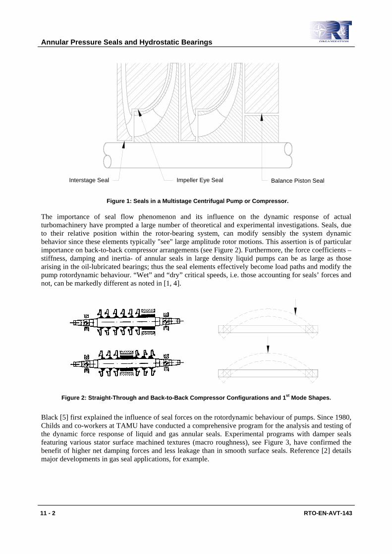
Interstage Seal Impeller Eye Seal Balance Piston Seal
Figure 1: Seals in a Multistage Centrifugal Pump or Compressor.
The importance of seal flow phenomenon and its influence on the dynamic response of actual turbomachinery have prompted a large number of theoretical and experimental investigations. Seals, due to their relative position within the rotor-bearing system, can modify sensibly the system dynamic behavior since these elements typically "see" large amplitude rotor motions. This assertion is of particular importance on back-to-back compressor arrangements (see Figure 2). Furthermore, the force coefficients – stiffness, damping and inertia- of annular seals in large density liquid pumps can be as large as those arising in the oil-lubricated bearings; thus the seal elements effectively become load paths and modify the pump rotordynamic behaviour. “Wet” and “dry” critical speeds, i.e. those accounting for seals’ forces and not, can be markedly different as noted in [1, 4].
Figure 2: Straight-Through and Back-to-Back Compressor Configurations and 1st Mode Shapes.
Black [5] first explained the influence of seal forces on the rotordynamic behaviour of pumps. Since 1980, Childs and co-workers at TAMU have conducted a comprehensive program for the analysis and testing of the dynamic force response of liquid and gas annular seals. Experimental programs with damper seals featuring various stator surface machined textures (macro roughness), see Figure 3, have confirmed the benefit of higher net damping forces and less leakage than in smooth surface seals. Reference [2] details major developments in gas seal applications, for example.

Annular Pressure Seals and Hydrostatic Bearings
RTO-EN-AVT-143 11 - 3
Figure 3: Honeycomb Seal for Turbopump.
This lecture presents:
a) The physical mechanism by which a direct stiffness arises in annular pressure seals even without journal (shaft) rotation. The model analyzes the flow balance and pressure drops at the entrance of a channel and on the ensuing thin film land. A maximum (optimum) stiffness is then predicted for a certain flow resistance balance between the entrance and land pressure drops.
b) Brief description of the bulk-flow equations for prediction of the flow and force coefficients in annular pressure seals.
c) Discussion of predictions for two water seals, long and short, for application as neck ring and interstage seals. The influences of seal length and inlet swirl on the rotordynamic force coefficients are thoroughly discussed.
Refer to Childs [1] and San Andrés [6] for a critical review of the archival literature related to the chronological developments in annular pressure seal analyses as well as experimental results validating the model predictions.
This lecture content material does not include a discussion on labyrinth seals or deep groove seals for liquid pump applications. Labyrinth seals are more common in centrifugal compressors.
Non-contacting face seal technology has reached great maturity for specialized pumps handling chemically harmful fluids. This type of sealing system is not presented here, see [7] for details.
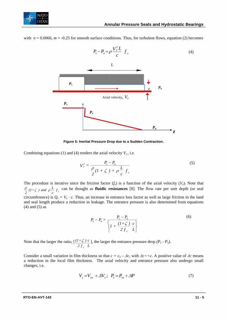
1.1 Generation of Stiffness in a Sudden Film Contraction [8] Figure 4 shows the typical geometry of an annular pressure seal. Fluid at a high pressure (Ps) flows through an annular gap of radial clearance (c) and discharges at the exit pressure (Pa). L and D represent the seal length and diameter, respectively.
Annular Pressure Seals and Hydrostatic Bearings
11 - 4 RTO-EN-AVT-143
L
shaft D
c
Ps Pa
Process
Axial velocity, Vz
fluid at high
Exit pressure
Figure 4: Geometry of an Annular Pressure Seal.
The principle by which a direct stiffness originates in an annular seal is due to the inertial pressure drop at the seal inlet plane and its close interaction with the pressure drop (and flow resistance) within the seal film land. The entrance effect is solely due to fluid inertia accelerating the fluid from an upstream stagnant condition to a flow with high axial speed and reduced static pressure at the seal inlet. The effect is known as Lomakin, in honor of the named Russian engineer who discovered the phenomenon in the late 1950's.
In the following, the sealing fluid is regarded as incompressible and isoviscous and the turbulent flow through the film land fully developed. A similar analysis, though more laborious, can be conducted for compressible fluids (gases). Incidentally, laminar flow conditions may be easily accounted for in the following development [6].
Consider the flow through a channel of height c and length L, as shown in Figure 5. The channel is infinitely long in the direction perpendicular to the plane of the page. The fluid flows from a large plenum at pressure Ps, and as it enters the seal, there is a sudden pressure drop (and flow acceleration) at the sudden contraction. This Bernoulli-like effect is solely due to fluid inertia and expressed by,
V )+(1 21 - PP 2
zse ξρ= (1)
where Ρe is the fluid entrance pressure at the seal inlet, Vz is the bulk-flow axial velocity, and ξ is a non-isentropic (empirical) entrance loss coefficient (typical value ranging from 0.0 to 0.25). In equation (1), fluid stagnant conditions are considered well upstream of the seal inlet plane. Within the seal of land length L and small film clearance (c), a linear pressure drop evolves due to viscous (turbulent flow) effects, i.e.
LVc
k += PP z2z
aeµ
− (2)
where κz = 12 for laminar flow or azz Rf=κ for turbulent flow. Note that the axial velocity is constant along the thin film due to flow continuity, i.e. Vz · c = Qz. In turbulent flows, the shear parameter κz is a function of the axial flow Reynolds number (Ra). Using Hirs’ formulation [9],
R n =R ) R (n = R f = k 1 + maa
maazz ;
µρ c V = R z
a (3)
Annular Pressure Seals and Hydrostatic Bearings
RTO-EN-AVT-143 11 - 5
with n = 0.0066, m = -0.25 for smooth surface conditions. Thus, for turbulent flows, equation (2) becomes
f c
L VPP z
2z
ae ρ=− (4)
L
c Pa
Axial velocity, Vz
Ps
Ps
Pe
Pa
z
Figure 5: Inertial Pressure Drop due to a Sudden Contraction.
Combining equations (1) and (4) renders the axial velocity Vz , i.e.
f cL + ) + (1
2
PP = Vz
as2z
ρζρ− (5)
The procedure is iterative since the friction factor (fz) is a function of the axial velocity (Vz). Note that f
cL and ) + (1
2 zρζρ can be thought as fluidic resistances [8]. The flow rate per unit depth (or seal
circumference) is Qz = Vz · c. Thus, an increase in entrance loss factor as well as large friction in the land and seal length produce a reduction in leakage. The entrance pressure is also determined from equations (4) and (5) as
−−
Lc
f 2) + (1 + 1
PP = PP
z
asae ζ
(6)
Note that the larger the ratio, [Lc
f 2) + (1
z
ζ ], the larger the entrance pressure drop (Ps - Pe).
Consider a small variation in film thickness so that c = co – ∆c, with ∆c<<c. A positive value of ∆c means a reduction in the local film thickness. The axial velocity and entrance pressure also undergo small changes, i.e.
PPP;VVV eoezzoz ∆∆ +=+= (7)

Annular Pressure Seals and Hydrostatic Bearings
11 - 6 RTO-EN-AVT-143
A perturbation analysis of all variables, including the friction factors, leads to.
)zoz V (1
P - = V ζρ +
∆∆ ; ( )
( )( )
o
eos
aeo
aeo
cc
PP2 PP)+(m
+ 1
m)-(1 PP = P ∆
−−
−∆
2 (8)
If ∆P is positive, then ∆Vz is negative, i.e. when the film thickness decreases (-∆c<0) and ∆P raises, this produces a reduction in axial velocity Vz.
Integration of the pressure field over the channel length (L) and depth (B) produces a fluid film reaction force (F)
( ) ( ) cKF2LBPPdzPPBF oae
L
0a ∆+=−=∫ −= (9)
The static stiffness (K) equals
( )( )
( )
( )aso
eo
eo
eo PPc2LB
p12 p)2+(m + 1
m)-(1 p = K −
−
(10)
where as
aeoeo PP
PPp−−
= is an entrance pressure ratio. A dimensionless stiffness follows as:
( )( )
( )( )
p12 p)2+(m + 1
m)-(1 p = PP
c2LB
K K
eo
eo
eo
aso −
−= (11)
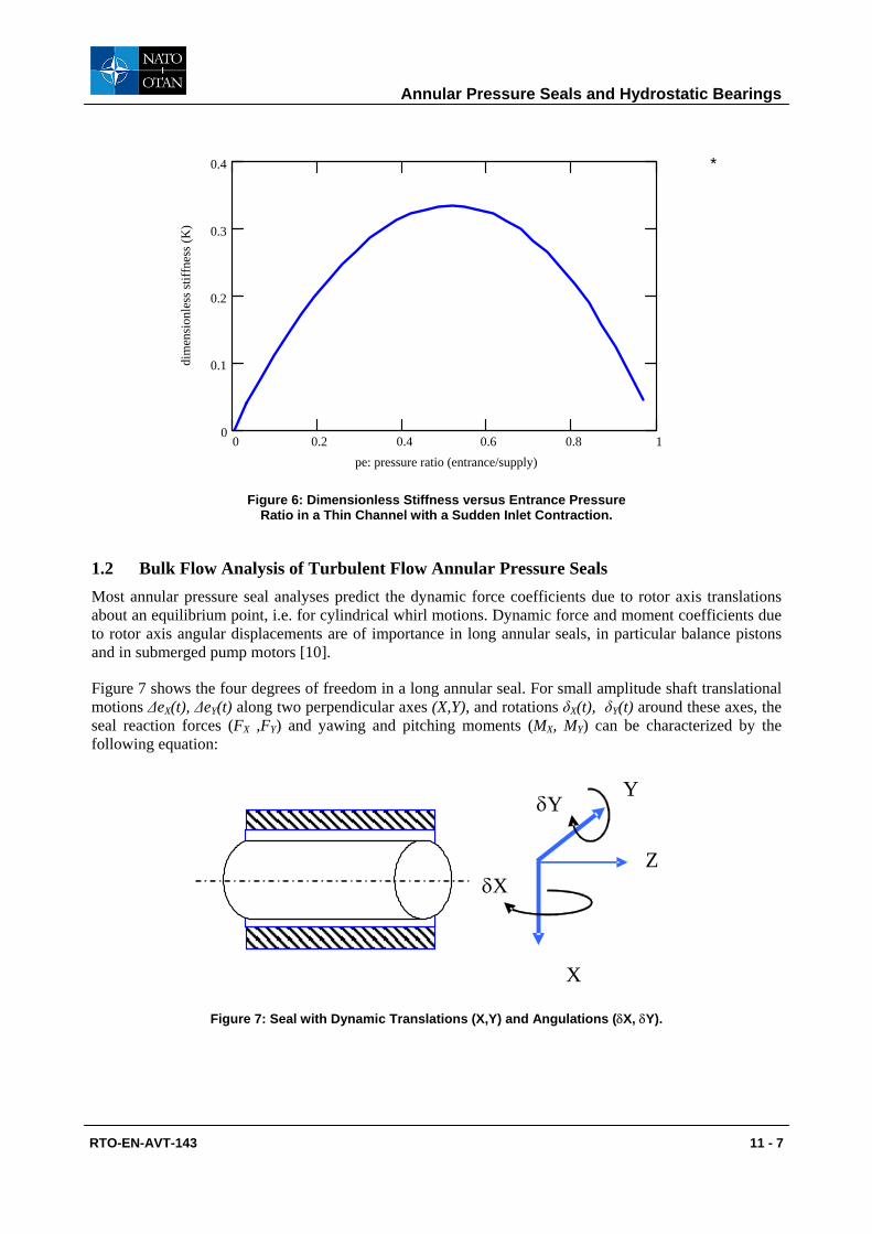
For smooth surfaces (m=-0.25), at peo=0.515 the stiffness is a maximum, maxK =0.3336. That is, an optimum stiffness arises when the inertial entrance pressure drop is slightly larger than 50% of the available pressure drop (Ps-Pa) across the channel length (L). Figure 6 displays the stiffness as a function of the entrance pressure ratio (peo). Small values of peo (→0) indicate too large entrance pressure losses due to fluid inertia, while too large values of peo (→1) show too much fluid resistance through the channel length (film land with tight clearance or overly long). None of these two conditions are favorable to induce a pronounced stiffening effect in an annular pressure seal.
Annular Pressure Seals and Hydrostatic Bearings
RTO-EN-AVT-143 11 - 7
0 0.2 0.4 0.6 0.8 10
0.1
0.2
0.3
0.4
pe: pressure ratio (entrance/supply)
dim
ensi
onle
ss st
iffne
ss (K
)*
Figure 6: Dimensionless Stiffness versus Entrance Pressure Ratio in a Thin Channel with a Sudden Inlet Contraction.
1.2 Bulk Flow Analysis of Turbulent Flow Annular Pressure Seals Most annular pressure seal analyses predict the dynamic force coefficients due to rotor axis translations about an equilibrium point, i.e. for cylindrical whirl motions. Dynamic force and moment coefficients due to rotor axis angular displacements are of importance in long annular seals, in particular balance pistons and in submerged pump motors [10].
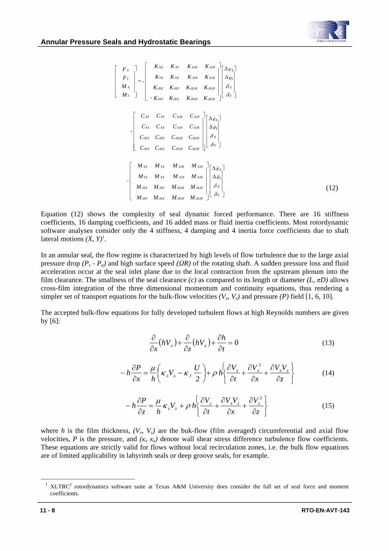
Figure 7 shows the four degrees of freedom in a long annular seal. For small amplitude shaft translational motions ∆eX(t), ∆eY(t) along two perpendicular axes (X,Y), and rotations δX(t), δY(t) around these axes, the seal reaction forces (FX ,FY) and yawing and pitching moments (MX, MY) can be characterized by the following equation:
X
Y
Z δX
δY
Figure 7: Seal with Dynamic Translations (X,Y) and Angulations (δX, δY).
Annular Pressure Seals and Hydrostatic Bearings
11 - 8 RTO-EN-AVT-143
∆∆
∆∆
∆∆
δδ
δδ
δδ
δδδδδδ
δδδδδδ
δδ
δδ
δδδδδδ
δδδδδδ
δδ
δδ
δδδδδδ
δδδδδδ
δδ
δδ
Y
X
Y
X
XXYXXXXY
YXXXXYXX
XXYXXXYX
YXXXXYXX
Y
X
Y
X
XXYXXXXY
YXXXXYXX
XXYXXXYX
YXXXXYXX
Y
X
Y
X
XXYXXXXY
YXXXXYXX
XXYXXXYX
YXXXXYXX
Y
X
Y
X
ee
MM MM
MMMM
MM MM
MMMM
-
ee
CC CC
CCCC
CC CC
CCCC
-
ee
KK KK -
KKKK
KK KK
KKKK
- =
MMFF
(12)
Equation (12) shows the complexity of seal dynamic forced performance. There are 16 stiffness coefficients, 16 damping coefficients, and 16 added mass or fluid inertia coefficients. Most rotordynamic software analyses consider only the 4 stiffness, 4 damping and 4 inertia force coefficients due to shaft lateral motions (X, Y)1.
In an annular seal, the flow regime is characterized by high levels of flow turbulence due to the large axial pressure drop (Ps - Pa) and high surface speed (ΩR) of the rotating shaft. A sudden pressure loss and fluid acceleration occur at the seal inlet plane due to the local contraction from the upstream plenum into the film clearance. The smallness of the seal clearance (c) as compared to its length or diameter (L, πD) allows cross-film integration of the three dimensional momentum and continuity equations, thus rendering a simpler set of transport equations for the bulk-flow velocities (Vx, Vz) and pressure (P) field [1, 6, 10].
The accepted bulk-flow equations for fully developed turbulent flows at high Reynolds numbers are given by [6]:
( ) ( ) 0=∂∂
+∂∂
+∂∂
thhV
zhV
x zx (13)
∂∂
+∂
∂+
∂∂
+
−=
∂∂
−zVV
xV
tV
hUVhx
Ph zxxxJxx
2
2ρκκµ
(14)
∂∂
+∂
∂+
∂∂
+=∂∂
−z
VxVV
tV
hVhz
Ph zzxzzz
2
ρκµ (15)
where h is the film thickness, (Vx, Vz) are the buk-flow (film averaged) circumferential and axial flow velocities, P is the pressure, and (κx κz) denote wall shear stress difference turbulence flow coefficients. These equations are strictly valid for flows without local recirculation zones, i.e. the bulk flow equations are of limited applicability in labyrinth seals or deep groove seals, for example.
1 XLTRC2 rotordynamics software suite at Texas A&M University does consider the full set of seal force and moment
coefficients.
Annular Pressure Seals and Hydrostatic Bearings
RTO-EN-AVT-143 11 - 9
Chapters 4 and 5 of Childs textbook [1] provide full descriptions of the analysis and dynamic force response for liquid and gas seals, respectively. San Andrés et al. [11, 12, and 13] extend the model above by including thermal effects and two-phase flow characterization, of importance in cryogenic liquid applications.
There is commercial software available for prediction of seal leakage and dynamic force coefficients. Most seal practitioners use programs predicting the performance of centered seals, i.e. operating at a null or zero eccentricity. The rationale assumes the seals are NOT load bearing elements. However, this assumption may be quite unrealistic in liquid turbopumps, for example. That is, liquid seals are “load” paths that can affect the load distribution on the support oil lubricated bearings.
The representation of seal forces for lateral motions (X, Y) is given as
−
−
−=
YX
MMMM
YX
CCCC
YX
KKKK
FF
YYYX
XYXX
YYYX
XYXX
YYYX
XYXX
Y
X (16)
where [K], [C], [M] represent the matrices of stiffness, damping and inertia force coefficients. Unlike in oil-lubricated bearings, added mass or fluid inertia coefficients are of great importance in liquid seals due to the fluid density and the large flow Reynolds numbers typical of seal flow operation. Seal analysis at a centered position shows that the direct force coefficients are identical while the cross-coupled coefficients are anti symmetric, i.e. KYY = K XX , K XY = -K YX, etc. Note that the seal force coefficients are frequency independent, i.e. remain constant for changes in excitation or whirl frequency. This assertion is correct only for (nearly) incompressible fluids such as water and liquid oxygen, for example. Other fluids, most notably gases and liquefied natural gas, are quite compressible. Seals in these applications will produce force coefficients which vary greatly with excitation frequency [3].
San Andrés [8] presents an analysis for fully developed flow through a centered short length annular pressure seal. For small amplitude perturbations in rotor center displacements, a closed form first-order flow field is determined from the linearized fluid flow equations. Close form expressions for the force coefficients due to shaft (rotor) displacements are then derived and compared with predictions from other analyses. The analytical formulation is simple and easy to implement during preliminary pump design stages and multi-variable parametric studies. A free software, MATHCAD® computational program, is available at the author’s URL site (http://phn.tamu.edu/TRIBGroup).
The prediction of annular seal static and dynamic force performance relies on the specification of
• seal geometry (length, diameter and clearance);
• operating conditions, speed and pressure supply and discharge;
• fluid properties (density and viscosity); and,
• empirical coefficients for the inlet pressure loss (ξ) and the inlet swirl ratio (α).
These last parameters are of extreme importance since the direct and cross-coupled stiffnesses depend directly on the seal entrance conditions. At the inlet to the seal section, the typical boundary conditions are
RVV +(1 21 - PP x
2zse Ω== αξρ ,) (17)
where Ρe is the fluid entrance pressure at the seal inlet, Vz is the bulk-flow axial velocity, and ξ is a non-isentropic (empirical) entrance loss coefficient. The inlet circumferential speed is a fraction of the rotor

Annular Pressure Seals and Hydrostatic Bearings
11 - 10 RTO-EN-AVT-143
speed (ΩR). α=0.50 denotes a 50% inlet swirl typical of an entrance condition into an inter-stage seal or balance piston, for example. α=~0.60 is more appropriate at the inlet of a neck-ring seal. As will be seen shortly, the inlet circumferential condition plays a significant role in the generation of cross-coupled stiffness coefficients, the culprit elements leading to rotordynamic instability. In short, an inlet swirl factor α=0.50 leads to a whirl frequency ratio of 50%, i.e. an annular seal is “as bad” as a plain journal bearing in terms of generating follower forces that drive forward whirl in rotating machinery.
Anti-swirl brakes, as shown in Figure 8, are used to reduce the pre-rotation of fluid into the seal, α→0. In this way, rotordynamic stability is ensured at the cost of mechanical complexity. Other fixes, in particular in long seals representing balance pistons, include implementing “shunt injection,” i.e. forcing liquid somewhere along the seal length in a direction opposite to shaft rotation in order to reduce the development of the circumferential flow speed.
rotor
Radial bafflesretarding fluid swirl Fluid path
Rotor speed
Seal
Figure 8: Anti Swirl Brake at Inlet or Pressure Seal.
The performance of annular seals is also affected by the condition of the rotor and stator surfaces. Since seals are regarded as rub elements, i.e. subjected to temporary conditions of rubbing at start up and shut down; in practice, predictions are obtained for two clearances, one representing the nominal design or manufactured clearance, and the other clearance at twice the nominal value to denote a worn seal condition in actual operation. These predictions are obtained to determine the effect of clearance on seal leakage rate, power loss and, most importantly, force coefficients affecting the rotor dynamics of the pump (or compressor). In liquid pumps, changes in clearance can affect greatly the direct stiffness thus moving the rotor-bearing system critical speeds (natural frequencies) and producing significant changes in damping ratio.
1.3 Performance of Short and Long Annular Seals for a Water Pump Predictions of leakage and force coefficients for two water seal configurations representing a neck ring seal (short length, L/D=0.2) and an inter-stage seal (~long seal L/D=0.5) follow. Table 1 shows the geometry of the smooth surfaces seals.
Table 1: Geometry and Operating Conditions of Water Seals in a Liquid Pump
D = 152. 4 mm, L/D=0.20 and 0.50 c=0.190 mm, nominal clearance smooth rotor and stator surfaces
Nominal speed = 3600 rpm and pressure drop 34.4 bar Inlet loss coefficient ξ=0.1, Inlet swirl α=0.5 and 0.0
Fluid: water at 30°C ( 0.792 cPoise, 995 kg/m3)

Annular Pressure Seals and Hydrostatic Bearings
RTO-EN-AVT-143 11 - 11
The analysis shows results for the nominal clearance and twice its value representing a worn condition. In addition, an inlet swirl of 50% represents a fluid with an entrance circumferential velocity equal to 50% of rotor surface speed. The swirl factor α=0 denotes the seal with an anti-swirl brake located at the seal inlet. The pressure drop across the seal varies in a quadratic form with rotor speed, ∆P ~ Ω2, with the nominal condition noted in the table. The speed range for the predictions is 1,000 to 5,000 rpm.
In the following figures, the left graphs show predictions for the long seal (L/D=0.50) while on the right, L/D=0.20. In addition, the predictions are shown are for the condition of inlet swirl at 50% rotor speed, unless otherwise stated. That is, the change in inlet swirl does not affect significantly several of the seal flow performance parameters. When important, the graphs and discussion will focus on this aspect.
Inlet Pressure: Figure 9 depicts the supply pressure into the seal increasing with rotor speed. The entrance pressures are lower for the worn seal (2c) due to an increase in flow rate that magnifies the fluid inertia inlet effect. The short seal shows a larger entrance pressure drop since the flow rate across the seal is larger (larger axial flow velocity). Inlet swirl has a minimal effect on the entrance pressure into the seal.
Pressures vs shaft speed
0
10
20
30
40
50
60
70
0 1000 2000 3000 4000 5000 6000
Rotor Speed (RPM)
Supp
ly p
ress
ure
Supply pressureNominal clearance (C)Twice clearance (worn)
No effect of inlet swirl on entrance pressure
bar operating speed3600 rpm
water seal, L/D=0.50, c=0.190 mm, D=152 mm
L/D=0.50
Pressures vs shaft speed
0
10
20
30
40
50
60
70
0 1000 2000 3000 4000 5000 6000
Rotor Speed (RPM)
Supp
ly p
ress
ure
Supply pressureNominal clearance (C)Twice clearance (worn)
No effect of inlet swirl on entrance pressure
bar operating speed3600 rpm
water seal, L/D=0.20, c=0.190 mm, D=152 mm
L/D=0.20
Figure 9: Supply and Entrance Pressures for Two Water Seals, L/D=0.50 and 0.20, and Two Clearances (c and 2c) versus Rotor Speed.
Flow Rate: Figure 10 shows the worn seals (enlarged clearances) leak more than at the nominal clearance condition. The short length seals have a larger flow rate in spite of the reduced entrance pressure. The penalty in leakage increase as the seal wears will affect the overall efficiency of the liquid pump. Inlet swirl has no discernible effect on seal leakage. The seal leakage appears as proportional to shaft speed. However, its variation is proportional to ∆P1/2. Recall that the pressure drop varies with rotor speed, Ω2.
Drag Power: Figure 11 shows that the long seals (L/D=0.5) have a larger drag power (torque x rotational speed) than the short length seals due to the larger area of fluid flow shearing. Inlet swirl is not significant in spite that the mean flow circumferential speed may be much less than 50% of rotor surface speed.

Annular Pressure Seals and Hydrostatic Bearings
11 - 12 RTO-EN-AVT-143
Leakage vs shaft speed
0
2
4
6
8
10
12
14
16
18
0 1000 2000 3000 4000 5000 6000
Rotor Speed (RPM)
Flow
rate
Nominal clearance (C)Twice clearance (worn)
No effect of inlet swirl
kg/s operating speed3600 rpm
water seal, L/D=0.50, c=0.190 mm, D=152 mm
L/D=0.50
Leakage vs shaft speed
0
2
4
6
8
10
12
14
16
18
0 1000 2000 3000 4000 5000 6000
Rotor Speed (RPM)
Flow
rate
Nominal clearance (C)Twice clearance (worn)
No effect of inlet swirl
kg/s operating speed3600 rpm
water seal, L/D=0.20, c=0.190 mm, D=152 mm
L/D=0.20 Figure 10: Leakage (Flow Rate) for Two Water Seals, L/D=0.50 and 0.20,
and Two Clearances (c and 2c) versus Rotor Speed.
Power vs shaft speed
0
1
2
3
4
5
6
0 1000 2000 3000 4000 5000 6000
Rotor Speed (RPM)
Dra
g Po
wer
Nominal clearance (C)Twice clearance (worn)"" no swirl
minor effect of inlet swirl
kW operating speed3600 rpm
water seal, L/D=0.50, c=0.190 mm, D=152 mm
L/D=0.50
Power vs shaft speed
0
1
2
3
4
5
6
0 1000 2000 3000 4000 5000 6000
Rotor Speed (RPM)
Dra
g Po
wer
Nominal clearance (C)Twice clearance (worn)"" no swirl
minor effect of inlet swirl
kW operating speed3600 rpm
water seal, L/D=0.20, c=0.190 mm, D=152 mm
L/D=0.20 Figure 11: Drag Power for Two Water Seals, L/D=0.50 and 0.20,
and Two Clearances (c and 2c) versus Rotor Speed.
Direct Stiffnesses: Figure 12 depicts the direct stiffness coefficients, KXX=KYY, increasing rapidly with rotor speed, i.e. with supply (or entrance) pressure. The direct stiffness for the long seal is about twice as large as for the short seal, and comparable in magnitude to the stiffnesses of any oil lubricated bearing, for example. The worn seals show a dramatic reduction in direct stiffness. For example, at the nominal operating condition of 3,600 rpm, the direct stiffnesses are ~50% of the values for the nominal clearances. This stiffness reduction will affect considerably the rotordynamic behaviour of a liquid pump. Recall that “wet” critical speeds depend on the seal direct stiffnesses which clearly drop as the seal wears out.
Direct Stiffness vs shaft speed
0.0
10.0
20.0
30.0
40.0
50.0
60.0
0.0 1000.0 2000.0 3000.0 4000.0 5000.0 6000.0
Rotor Speed (RPM)
Stiff
ness
Nominal clearance (C)Twice clearance (worn)""no swirl
negligible effect of inlet swirl
Kxx=Kyy [MN/m]
operating speed3600 rpm
water seal, L/D=0.50, c=0.190 mm, D=152 mm
L/D=0.50
Direct Stiffness vs shaft speed
0.0
10.0
20.0
30.0
40.0
50.0
60.0
0.0 1000.0 2000.0 3000.0 4000.0 5000.0 6000.0
Rotor Speed (RPM)
Stiff
ness
Nominal clearance (C)Twice clearance (worn)""no swirl
negligible effect of inlet swirl
Kxx=Kyy [MN/m]
operating speed3600 rpm
water seal, L/D=0.20, c=0.190 mm, D=152 mm
L/D=0.20 Figure 12: Direct Stiffness Coefficients for Two Water Seals, L/D=0.50
and 0.20, and Two Clearances (c and 2c) versus Rotor Speed.
Annular Pressure Seals and Hydrostatic Bearings
RTO-EN-AVT-143 11 - 13
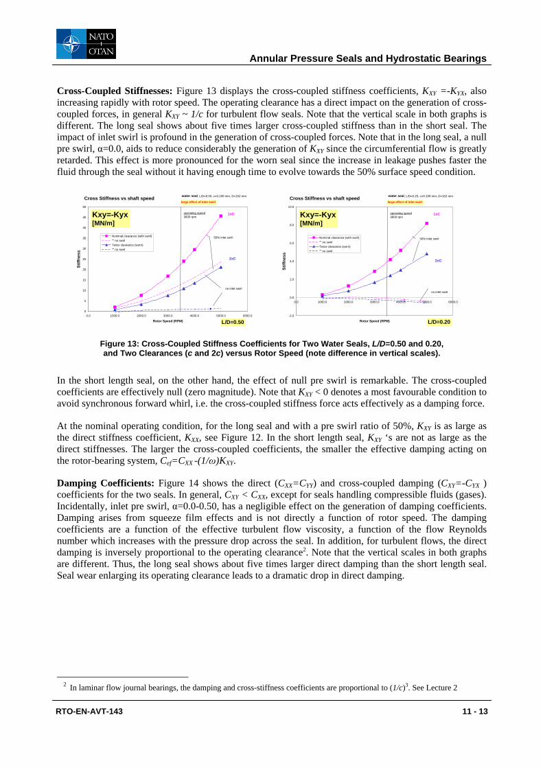
Cross-Coupled Stiffnesses: Figure 13 displays the cross-coupled stiffness coefficients, KXY =-KYX, also increasing rapidly with rotor speed. The operating clearance has a direct impact on the generation of cross-coupled forces, in general KXY ~ 1/c for turbulent flow seals. Note that the vertical scale in both graphs is different. The long seal shows about five times larger cross-coupled stiffness than in the short seal. The impact of inlet swirl is profound in the generation of cross-coupled forces. Note that in the long seal, a null pre swirl, α=0.0, aids to reduce considerably the generation of KXY since the circumferential flow is greatly retarded. This effect is more pronounced for the worn seal since the increase in leakage pushes faster the fluid through the seal without it having enough time to evolve towards the 50% surface speed condition.
Cross Stiffness vs shaft speed
0
5
10
15
20
25
30
35
40
45
50
0.0 1000.0 2000.0 3000.0 4000.0 5000.0 6000.0
Rotor Speed (RPM)
Stiff
ness
Nominal clearance (with swirl)"" no swirlTwice clearance (worn)"" no swirl
large effect of inlet swirl
Kxy=-Kyx [MN/m]
operating speed3600 rpm
water seal, L/D=0.50, c=0.190 mm, D=152 mm
no inlet swirl
1xC
2xC
50% inlet swirl
L/D=0.50
Cross Stiffness vs shaft speed
-2.0
0.0
2.0
4.0
6.0
8.0
10.0
0.0 1000.0 2000.0 3000.0 4000.0 5000.0 6000.0
Rotor Speed (RPM)
Stiff
ness
Nominal clearance (with swirl)"" no swirlTwice clearance (worn)"" no swirl
large effect of inlet swirl
Kxy=-Kyx [MN/m]
operating speed3600 rpm
water seal, L/D=0.20, c=0.190 mm, D=152 mm
no inlet swirl
1xC
2xC
50% inlet swirl
L/D=0.20
Figure 13: Cross-Coupled Stiffness Coefficients for Two Water Seals, L/D=0.50 and 0.20, and Two Clearances (c and 2c) versus Rotor Speed (note difference in vertical scales).
In the short length seal, on the other hand, the effect of null pre swirl is remarkable. The cross-coupled coefficients are effectively null (zero magnitude). Note that KXY < 0 denotes a most favourable condition to avoid synchronous forward whirl, i.e. the cross-coupled stiffness force acts effectively as a damping force.
At the nominal operating condition, for the long seal and with a pre swirl ratio of 50%, KXY is as large as the direct stiffness coefficient, KXX, see Figure 12. In the short length seal, KXY ‘s are not as large as the direct stiffnesses. The larger the cross-coupled coefficients, the smaller the effective damping acting on the rotor-bearing system, Cef=CXX -(1/ω)KXY.
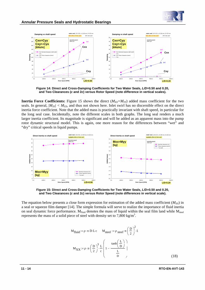
Damping Coefficients: Figure 14 shows the direct (CXX=CYY) and cross-coupled damping (CXY=-CYX ) coefficients for the two seals. In general, CXY < CXX, except for seals handling compressible fluids (gases). Incidentally, inlet pre swirl, α=0.0-0.50, has a negligible effect on the generation of damping coefficients. Damping arises from squeeze film effects and is not directly a function of rotor speed. The damping coefficients are a function of the effective turbulent flow viscosity, a function of the flow Reynolds number which increases with the pressure drop across the seal. In addition, for turbulent flows, the direct damping is inversely proportional to the operating clearance2. Note that the vertical scales in both graphs are different. Thus, the long seal shows about five times larger direct damping than the short length seal. Seal wear enlarging its operating clearance leads to a dramatic drop in direct damping.
2 In laminar flow journal bearings, the damping and cross-stiffness coefficients are proportional to (1/c)3. See Lecture 2
Annular Pressure Seals and Hydrostatic Bearings
11 - 14 RTO-EN-AVT-143
Damping vs shaft speed
0
20
40
60
80
100
120
140
160
180
200
0.0 1000.0 2000.0 3000.0 4000.0 5000.0 6000.0
Rotor Speed (RPM)
Dam
ping
Cxx Nominal clearance (with swirl)CxyCxx Twice clearance (worn)Cxy
little effect of inlet swirl
Cxx=CyyCxy=-Cyx [kNs/m]
operating speed3600 rpm
water seal, L/D=0.50, c=0.190 mm, D=152 mm
1xC
2xC
50% inlet swirl
Cxx
Cxy
L/D=0.50
Damping vs shaft speed
0
5
10
15
20
25
30
35
40
45
50
0.0 1000.0 2000.0 3000.0 4000.0 5000.0 6000.0
Rotor Speed (RPM)
Dam
ping
Cxx Nominal clearance (with swirl)CxyCxx Twice clearance (worn)Cxy
little effect of inlet swirl
Cxx=CyyCxy=-Cyx [kNs/m]
operating speed3600 rpm
water seal, L/D=0.20, c=0.190 mm, D=152 mm
1xC
2xC
50% inlet swirl
Cxx
Cxy
L/D=0.20 Figure 14: Direct and Cross-Damping Coefficients for Two Water Seals, L/D=0.50 and 0.20,
and Two Clearances (c and 2c) versus Rotor Speed (note difference in vertical scales).
Inertia Force Coefficients: Figure 15 shows the direct (MXX=MYY) added mass coefficient for the two seals. In general, |MXY| < MXX, and thus not shown here. Inlet swirl has no discernible effect on the direct inertia force coefficient. Note that the added mass is practically invariant with shaft speed, in particular for the long seal case. Incidentally, note the different scales in both graphs. The long seal renders a much larger inertia coefficient. Its magnitude is significant and will be added as an apparent mass into the pump rotor dynamic structural model. This is again, one more reason for the differences between “wet” and “dry” critical speeds in liquid pumps.
Direct Inertia vs shaft speed
0
5
10
15
20
25
30
35
40
45
50
0.0 1000.0 2000.0 3000.0 4000.0 5000.0 6000.0
Rotor Speed (RPM)
Add
ed m
ass
Nominal clearance (C)Twice clearance (worn)""no swirl
negligible effect of inlet swirl
Mxx=Myy [kg]
operating speed3600 rpm
water seal, L/D=0.50, c=0.190 mm, D=152 mm
L/D=0.50
Direct Inertia vs shaft speed
0.0
0.5
1.0
1.5
2.0
2.5
3.0
3.5
4.0
4.5
5.0
0.0 1000.0 2000.0 3000.0 4000.0 5000.0 6000.0
Rotor Speed (RPM)
Add
ed m
ass
Nominal clearance (C)Twice clearance (worn)""no swirl
negligible effect of inlet swirl
Mxx=Myy [kg]
operating speed3600 rpm
water seal, L/D=0.20, c=0.190 mm, D=152 mm
L/D=0.20 Figure 15: Direct and Cross-Damping Coefficients for Two Water Seals, L/D=0.50 and 0.20,
and Two Clearances (c and 2c) versus Rotor Speed (note differences in vertical scale).
The equation below presents a close form expression for estimation of the added mass coefficient (MXX) in a seal or squeeze film damper [14]. The simple formula will serve to realize the importance of fluid inertia on seal dynamic force performance. Mfluid denotes the mass of liquid within the seal film land while Msteel represents the mass of a solid piece of steel with density set to 7,800 kg/m3.
(18)
Mfluid ρ π⋅ D⋅ L⋅ c⋅:= Msteel ρ steel π⋅D2
⎛⎜⎝
⎞⎟⎠
2⋅ L⋅:=
MXX ρ π⋅D2
⎛⎜⎝
⎞⎟⎠
3⋅
Lc
⋅ 1tanh
LD
⎛⎜⎝
⎞⎟⎠
L
D
−
⎛⎜⎜⎜⎝
⎞⎟⎟⎟⎠
⋅:=

Annular Pressure Seals and Hydrostatic Bearings
RTO-EN-AVT-143 11 - 15
The calculated values for the short and long seals and nominal clearance are
MXX 2.91kg=LD
0.2=
Mfluid 2.76 10 3−× kg= MXX
Msteel0.67=
Msteel 4.34kg=
MXX 42.03kg=LD
0.5=
Mfluid 6.9 10 3−× kg= MXX
Msteel3.88=
Msteel 10.84kg=
Although the mass of water contained within the seal land is just a few grams, the seal added mass coefficient is orders of magnitude larger. The added mass or inertia coefficient (MXX) is of the same order of magnitude, and for L/D=0.5 even larger, than the mass of a solid piece of rotor of identical length. The approximate formula is very good for quick estimations of added mass coefficients, as a direct comparison to the numerical results shown in Figure 15 attests.
Whirl Frequency Ratio: Figure 16 depicts the stability indicator (WFR) for the two seals. With an inlet pre-swirl equal to 50% of rotor speed, the WFR is always 0.50. In this case, KXY /(Ω CXX) =0.50, indicates that the pump can not operate at a sped above twice the critical speed of the rotor-bearing-seal system. Furthermore, consider that this critical speed is the “wet” one, i.e. lower than the “dry” critical speed, since fluid inertia effects will aid to reduce the “dry” natural frequency.
Whirl ratio vs shaft speed
0.0
0.1
0.2
0.3
0.4
0.5
0.6
0.0 1000.0 2000.0 3000.0 4000.0 5000.0 6000.0
Rotor Speed (RPM)
Whi
rl fr
eque
ncy
ratio
Nominal clearance (with swirl)"" no swirlTwice clearance (worn)"" no swirl
large effect of inlet swirl
WFR operating speed3600 rpm
water seal, L/D=0.50, c=0.190 mm, D=152 mm
no inlet swirl
1xC
2xC
50% inlet swirl
L/D=0.50
Whirl ratio vs shaft speed
0.0
0.1
0.2
0.3
0.4
0.5
0.6
0.0 1000.0 2000.0 3000.0 4000.0 5000.0 6000.0
Rotor Speed (RPM)
Whi
rl fr
eque
ncy
ratio
Nominal clearance (with swirl)"" no swirlTwice clearance (worn)"" no swirl
large effect of inlet swirl
WFR operating speed3600 rpm
water seal, L/D=0.20, c=0.190 mm, D=152 mm
no inlet swirl
1xC2xC
50% inlet swirl
negative values
L/D=0.20
Figure 16: Whirl Frequency Ratio for Two Water Seals, L/D=0.50 and 0.20, and Two Clearances (c and 2c) versus Rotor Speed (note difference in vertical scales).
The effect of an anti-swirl break on the performance of the seal is dramatic. For a condition of no pre-swirl, the short length seal actually presents a negative whirl frequency ratio, meaning that the seal is impervious to (unstable) forward rotor whirl motions. The effect of the null pre-swirl is less notorious in the long seal, since the fluid flowing through the seal does have enough “residence” time to develop a circumferential mean flow velocity approaching the 50% rotor speed. Clearly, swirl brakes are inefficient devices for very long seals, L/D > 1, as it would be the case of a balance piston, for example.
Extensive testing has shown that seals with macroscopic roughness; i.e. textured stator surfaces, offer major improvements in reducing leakage as well as cross-coupled stiffness coefficients [2]. Figure 17

Annular Pressure Seals and Hydrostatic Bearings
11 - 16 RTO-EN-AVT-143
depicts two textured seals and a conventional labyrinth seal (teeth on stator). A textured surface like a round-hole pattern or a honeycomb increases the friction thus reducing leakage, and aids to retard the development of the circumferential flow velocity -the physical condition generating the cross-coupled stiffness coefficients. However, surface texturing on the rotor works the other way around while still reducing leakage, i.e. the circumferential flow develops faster causing even more severe rotordynamic instabilities. In the past 10 years, compressor and pump manufacturers (as well as users) are implementing efficiently textured seals with great commercial success [15].
Unwrap
UnwrapHoneycomb Seal
Hole-Pattern Seal
Labyrinth Seal
Figure 17: Hole-Pattern, Honeycomb and Labyrinth Seal Configurations.
2.0 HYDROSTATIC BEARINGS FOR PUMP APPLICATIONS
Hydrostatic bearings derive their load capacity not from shear flow driven effects (hydrodynamic wedge and surface sliding) but rather from the combination of pressure versus flow resistance effects through a feed restrictor and within the bearing film lands. Hydrostatic bearings can support large loads without journal rotation and provide large (accurate and controllable) direct stiffness as well as damping coefficients. The hydrostatic stiffness is of unique importance for the centering of high-precision milling machines, gyroscopes, large arena movable seating areas, telescope bearings, and even cryogenic fluid turbo pumps for rocket engines.
Note that hydrostatic bearings require an external pressurized supply system and some type of flow restrictor. Also, under dynamic motions, hydrostatic bearings may display a pneumatic hammer effect due to fluid compressibility. However, and most importantly, the load and static stiffness of a hydrostatic bearing are independent of fluid viscosity; thus making this bearing type very attractive for cryogenic liquid turbopumps or low viscosity process fluid pump applications.
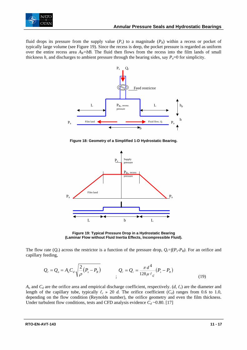
2.1 Estimation of the Static Stiffness in a Simple Hydrostatic Bearing [16] Consider the fundamental operation of a simple one dimensional hydrostatic bearing. The flow is laminar and fluid inertia effects are not accounted for; i.e. a classical lubrication example. Figure 18 depicts a 1D bearing of very large width (B). A hydrostatic bearing combines two flow restrictions in series, one at the feed or supply port, and the other through the film lands. In the feed restrictor (orifice, capillary, etc.) the
Annular Pressure Seals and Hydrostatic Bearings
RTO-EN-AVT-143 11 - 17
fluid drops its pressure from the supply value (Ps) to a magnitude (PR) within a recess or pocket of typically large volume (see Figure 19). Since the recess is deep, the pocket pressure is regarded as uniform over the entire recess area AR=bB. The fluid then flows from the recess into the film lands of small thickness h, and discharges to ambient pressure through the bearing sides, say Pa=0 for simplicity.
L
h Fluid flow, Ql
Qr
b
hp L
Ps
PaPa
PR, recess pressure
Feed restrictor
Film land
Figure 18: Geometry of a Simplified 1-D Hydrostatic Bearing.
L
Supply pressure
b L
Ps
PaPa
PR, recess pressure
Film land
Figure 19: Typical Pressure Drop in a Hydrostatic Bearing (Laminar Flow without Fluid Inertia Effects, Incompressible Fluid).
The flow rate (Qr) across the restrictor is a function of the pressure drop, Qt=f(Ps-PR). For an orifice and capillary feeding,
( )Rsdoor PPCAQQ −==
ρ2
; ( )Rscr PPQQ
c
d −==µ
π128
4
(19)
Ao and Cd are the orifice area and empirical discharge coefficient, respectively. (d, ℓc) are the diameter and length of the capillary tube, typically ℓc » 20 d. The orifice coefficient (Cd) ranges from 0.6 to 1.0, depending on the flow condition (Reynolds number), the orifice geometry and even the film thickness. Under turbulent flow conditions, tests and CFD analysis evidence Cd ~0.80. [17]

Annular Pressure Seals and Hydrostatic Bearings
11 - 18 RTO-EN-AVT-143
Across the bearing film lands the fluid drops in pressure from (PR) to ambient pressure, Pa. In the laminar flow of an incompressible fluid, the flow rate is a function of the pressure drop and equals
( )L
PPhBxPhB aRQ
µµ 1212
33 −∂∂ +=−= (20)
where B is the bearing width and L is the film length with thickness h. Presently, no surface motion along the x-axis is accounted for, i.e. the bearing is stationary. Under steady state conditions, the flow through the restrictor equals the flow through the film lands, i.e.
( ) laRlRsr QPPCPPfQ 2)(2 =−=−= (21)
with Cl = B h3/(12 µ L) as a flow-conductance along the film land. The flow conductance is the inverse of a flow resistance. Equation (21) allows the determination of the recess pressure (PR) given the film conductance (Cl) and feed restrictor parameters. For bearing design, a value of pocket pressure (PR) is desired, and equation (21) serves to size the diameter of the supply restrictor.
For the simple bearing considered, the pressure field on the bearing surface takes the shape shown in Figure 19. Note that the recess pressure is assumed uniform or constant within the pocket extent (b). The assertion is not valid for flows with large Reynolds numbers (highly turbulent), shallow pockets and with large journal rotational speeds, as will be seen later [18]. The film pressure generates a reaction force,
RRRR PbLBPbPPBdxxPBF LL )()(22
+=++=∫=
(22)
where Pa=0 for simplicity. The force (F) is proportional to the recess pressure (PR) and the area B (L + b). Note that, in the absence of surface relative motion, a hydrostatic bearing has a limit load capacity, [B(L+b)]Ps.
A static change in film thickness (h0+∆h) with ∆h « h0, causes the recess pressure to change to PRo +∆PR, since the flow conductance varies. ∆PR <0 as ∆h>0. Integration of the change in pressure gives rise to a the hydrostatic stiffness: [16]
)1()(3
++=
∆∆−=
ZP
hbLB
hFK Ro
o
(23)
with ( ) ( )( )Ros
aRoRo PPa
PPPZZ−−== , a = 2 for orifice or a = 1 for capillary feed. The hydrostatic stiffness is
proportional to the bearing area [B(L+b]), the recess pressure (PRo), and inversely proportional to the film thickness (ho). Most importantly, the stiffness is not an explicit function of fluid viscosity. Figure 20 depicts the dimensionless stiffness,
1)(3 +
=+⋅=
Zp
PbLBhKK ro
s
o (24)
versus the recess pressure ratio, pro=PRo/Ps. for bearings with orifice and capillary feeds, respectively. Hydrostatic bearings with orifice compensation have larger stiffness than capillary fed bearings. Orifices are usually preferred since their diameters are larger than those of capillaries. This is important since restrictor clogging may cause catastrophic bearing failure, unless a micron size filtering device is used as part of the fluid feed (supply) system into the bearing.

Annular Pressure Seals and Hydrostatic Bearings
RTO-EN-AVT-143 11 - 19
0 0.2 0.4 0.6 0.8 10
0.2
0.4
orificecapillary
Dimensionless stiffness for simple HB
pocket pressur ratio (Pr/Ps)
stiff
ness
(dim
ensi
onle
ss)
Figure 20: Static Stiffness for Simple Hydrostatic Bearing (Laminar Flow w/o Fluid Inertia Effects, Incompressible Fluid).
A maximum hydrostatic stiffness occurs for a given recess pressure ratio. For a capillary (pro=0.50) while for an orifice (pro=0.5857). In a capillary fed hydrostatic bearing, the pressure drops across the restrictor should match the pressure drop across the film lands. The optimum stiffness arises from an impedance matching between the feed restrictor and the flow resistance through the film lands. In the figure, a low value of recess pressure indicates a large flow resistance (small conductance) through the restrictor, while a large recess pressure denotes a large flow resistance through the film lands.
In sum, hydrostatic bearings with orifice restrictors offer larger stiffness than with capillary restrictors. The bearing direct stiffness depends on the pocket pressure (< supply pressure) and does not dependent explicitly on lubricant viscosity. Without an external pressure supply and restrictor, there is no stiffness or load support.
2.1 Effects of Excitation Frequency, Pocket Volume and Fluid Compressibility on the Force Coefficients of a Hybrid Bearing
The prior analysis explained the physics for the generation of support stiffness in a hydrostatic bearing. The stiffness derived is static, strictly valid for low frequency motions. Motions at other frequencies produce notable changes in both the stiffness and damping force coefficients. Below, hydrodynamic effects (surface velocity) and fluid compressibility within the recess volume are accounted for [19]. A hybrid bearing combines the hydrodynamic and hydrostatic effects due to surface motion and external pressurization, respectively. Figure 21 depicts the simple 1D-bearing configuration analyzed next.

Annular Pressure Seals and Hydrostatic Bearings
11 - 20 RTO-EN-AVT-143
L
h Fluid flow, Ql
Qr
b
hp L
Ps
Pa Pa
PR, recess pressure
Feed restrictor
Film land
Figure 21: Simple Hybrid (Hydrostatic/Hydrodynamic) Bearing with Surface Speed (U).
The conservation of mass within the recess of a hydrostatic bearing balances the flow through the restrictor (Qr), the flow into the film lands (2Ql) and the time rate of change of fluid mass accumulated within the pocket,
( )tV1Q2Q rec
lR ∂∂
=−ρ
ρ (25)
where Vrec=B d(h+hR) is the recess volume, h(t) is the film thickness, and hR is the machined pocket depth. In the thin film lands, the continuity and momentum transport equations for the laminar flow of an inertialess, isoviscous and (nearly) incompressible fluid are:
−=
∂∂
−=∂∂
+∂∂
2hUq12
xPh;0
th
xq
x3x µ (26)
where B
QhVq xxx == is the flow rate per unit width, and U is the bearing surface speed. Let the film
thickness be given as the superposition of a steady-state value (h0) and a harmonic motion of small amplitude ∆h and frequency (ω), i.e.
ti00 ehh)tcos(hhh ω∆ω∆ +=+= ; and tiehih ω∆ω= (27)
Note that only the real part of the complex expression above is of importance. For small amplitude motions (∆h<<h0), the film pressure (P) and flow rate (qx) are also given by the superposition of an equilibrium (zeroth-order) field and a dynamic (first-order) field, i.e.
tixxx
ti10 ehqqq;ehPPP
10
ωω ∆∆ +=+= (28)
The recess pressure (PR) and the flow (Ql) leaving the pocket into the film lands are also expressed as the sum of static and dynamic components. The density and pressure in a compressible liquid are related through the material bulk-modulus (κ), i.e. dPd
κρρ = . Thus
U
Annular Pressure Seals and Hydrostatic Bearings
RTO-EN-AVT-143 11 - 21
( ) tirec
Rrec
rec ehiAP
VtV1 1
0
ω∆ωκ
ρρ
+=
∂∂ (29)
with )( 00 Rrecrec hhAV += . Equation (29) shows that the fluid mass in the pocket volume will vary dynamically with changes in film thickness and pocket pressure, thus introducing a pressure-lag effect which can induce undesirable dynamic force effects, namely pneumatic hammer with generation of a “negative” damping coefficient. San Andrés [19] introduces a break frequency (ωB) as
( ) ( )LBh
VZ
VZ
PQ
recrecR
rB µ
κκω6
11 30
000
0 +=+
= (30)
Note that ωB→∞ for an incompressible fluid (κ→∞). A lengthy algebraic analysis leads to the following expressions for frequency dependent force coefficients [19],
( )( )( )20)(2
2
0)( f11CC;
f1
f1KK
+−
=+
+
=αα
ωω (31)
where B
fωω
= is a frequency ratio, oB
o
CK
ωα = is a damping loss ratio; and (K0, C0) are the stiffness and
damping coefficients obtained for an incompressible fluid, i.e. in the absence of liquid compressibility ( ∞→κ ), and equal to
( ) ( ))1Z(
1h
bLLB6C;)1Z(
Ph
bLB3K 30
2
0R
00
0
++
=+
+=
µ (32)
with ( ) ( )( )
0
0
Rs
aRRo PPa
PPPZZ
−
−==
Note that the static stiffness coefficient (K0) is directly proportional to the recess pressure (PR). On the other hand, the "static" damping coefficient (C0) depends solely on the fluid viscosity and the bearing area, and it grows rapidly as the film thickness (h) decreases. Incidentally, the surface speed (U) does not aid to the generation of force coefficients in laminar flow hydrostatic bearings.
Figure 22 shows the hydrostatic bearing stiffness (K) and damping (C) coefficients for increasing frequency ratios (ω/ωB). The results correspond to a bearing with deep a deep pocket depth (hR/h=10) and damping loss factor (α=0.42). In general, the hydrostatic stiffness increases as the excitation frequency grows while the damping coefficient drops dramatically. See [19] for a more detailed analysis with examples related to cryogenic fluid hydrostatic bearings.

Annular Pressure Seals and Hydrostatic Bearings
11 - 22 RTO-EN-AVT-143
0 1 2 3 40.1
1
10
K/KoC/Co
Coefficients for hydrostatic bearing
excitation frequency/break frequency
Dim
ensi
onle
ss st
iffne
ss a
nd d
ampi
ng
Figure 22: Frequency Dependent (Dimensionless) Force Coefficients for Simple Hydrostatic Bearing.
For excitations at low frequencies, ω→0 (ω <<ωB), the stiffness and damping coefficients approach
( )αωω −== == 1CC;KK 0)0(0)0( (33)
Thus, at low frequencies there is a loss of damping due to fluid compressibility effects (α>0). This reduction may cause the bearing to become unstable even under static conditions if the loss ratio (α) is larger than one. This phenomenon is known as pneumatic hammer and characteristic of gas hydrostatic bearings.
For excitations at large frequencies, (ω→∞, ω >>ωB),
0; )(0
)( === ∞→∞∞→ ωω αC
KKK (34)
there is a complete loss of damping accompanied by an increase in dynamic stiffness. For excitations at a frequency coinciding with the break frequency (ωB), the stiffness and damping coefficients are
( )ααα
−==+
= === 121
21;
21
)0()1()1( offof CCCKK (35)
Thus, the damping coefficient is just 50% of the value obtained at low frequencies.
The force coefficients are frequency independent in a nearly incompressible fluid (κ→0, ωB→∞). However, note that even in commonly assumed incompressible liquids, the fluid bulk modulus decreases rapidly with minute concentrations of dissolved gases.
To avoid fluid compressibility – pocket volume effects it is desirable to design the hydrostatic bearing with a break frequency (ωB) as large as possible and/or operate the bearing under dynamic conditions with excitation frequencies well below the break frequency, i.e. f<<1.

Annular Pressure Seals and Hydrostatic Bearings
RTO-EN-AVT-143 11 - 23
From equation (30), to increase the break frequency ratio, large values for the following ratio are needed,
+
=
0
20
30
1
166
1
0
hhLd
hLV
Bh
Rrec
.
That is, deep pockets (hR/h0>>1) tend to aggravate the loss of damping at low excitation frequencies.
It is notable to mention that the whirl frequency ratio for a centered hybrid bearing [19] is
( ) ( )ααφ
−≈
−Ω=
Ω==
===1
15.01
00 XX
XY
XX
XY
CK
CK
WFRf
(36)
Hence, hybrid bearings have the same limited whirl frequency ratio as plain cylindrical bearings. This ratio could even be worse, WFR > 0.5 if α > 0, i.e. if fluid compressibility –recess volume effects are important.
2.2 Hybrid (Hydrostatic/Hydrodynamic) Bearings for High Performance Turbopumps The importance of hybrid (combination hydrostatic and hydrodynamic) journal and thrust bearings and damping seal bearings as radial support elements in cryogenic turbomachinery has steadily grown over the past few years [20, 21]. Compact - low count part turbo pumps operate sub critically at exceedingly high shaft speeds (180 krpm) with pressure differentials as large as 550 bars. Advanced primary power require of externally pressurized fluid film bearings to support the expected large thrust and lateral radial loads. Hybrid journal bearings (HJB)s enable smaller and lighter turbopumps through no bearing DN life limitation and sub critical rotor operation, i.e. at speeds below the first elastic mode of the rotor-bearing system. HJBs offer durability, low friction and wear, accuracy of positioning, and large direct stiffness and damping force coefficients. These features enable the design (and operation) of un-shrouded impellers with a significant increase in the turbopump mechanical efficiency. The growth of an "all-fluid-film- bearing" technology for advanced and less costly (per launch cost) turbopumps demands the development of analytical models and design tools, the testing of components, and the implementation of the technology.
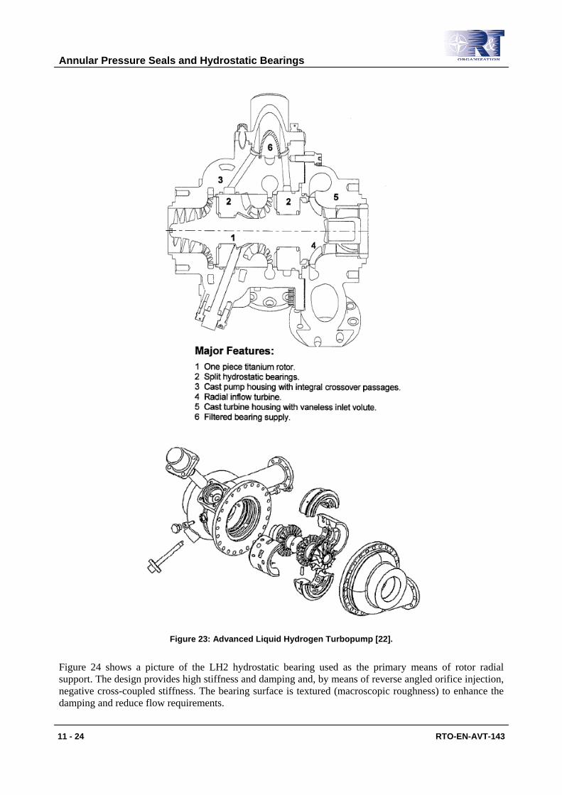
Figure 23 depicts an Advanced Liquid Hydrogen Turbopump developed by Pratt & Whitney in the late 1990’s. The compact turbopump integrates two LH2 lubricated hydrostatic radial bearings and a hydrostatic thrust bearing. Fluid pressure to the pump and turbine end bearings is supplied from the pump discharge volute. [22].
Annular Pressure Seals and Hydrostatic Bearings
11 - 24 RTO-EN-AVT-143
Figure 23: Advanced Liquid Hydrogen Turbopump [22].
Figure 24 shows a picture of the LH2 hydrostatic bearing used as the primary means of rotor radial support. The design provides high stiffness and damping and, by means of reverse angled orifice injection, negative cross-coupled stiffness. The bearing surface is textured (macroscopic roughness) to enhance the damping and reduce flow requirements.
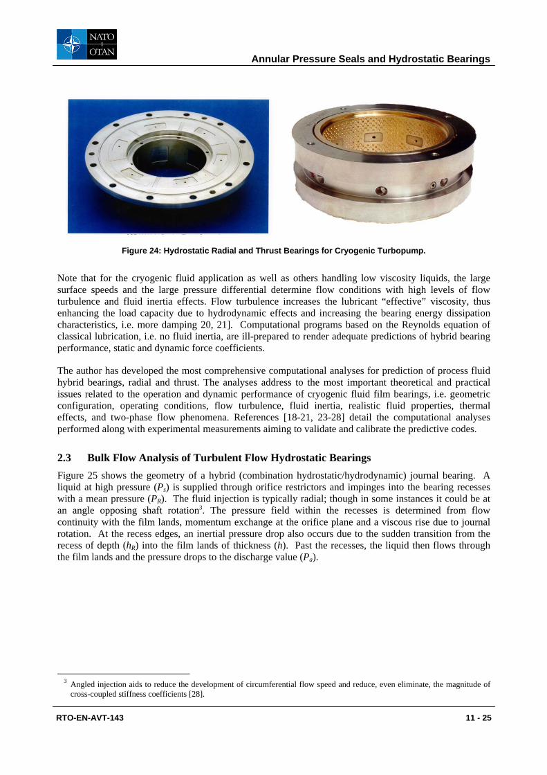
Annular Pressure Seals and Hydrostatic Bearings
RTO-EN-AVT-143 11 - 25
Figure 24: Hydrostatic Radial and Thrust Bearings for Cryogenic Turbopump.
Note that for the cryogenic fluid application as well as others handling low viscosity liquids, the large surface speeds and the large pressure differential determine flow conditions with high levels of flow turbulence and fluid inertia effects. Flow turbulence increases the lubricant “effective” viscosity, thus enhancing the load capacity due to hydrodynamic effects and increasing the bearing energy dissipation characteristics, i.e. more damping 20, 21]. Computational programs based on the Reynolds equation of classical lubrication, i.e. no fluid inertia, are ill-prepared to render adequate predictions of hybrid bearing performance, static and dynamic force coefficients.
The author has developed the most comprehensive computational analyses for prediction of process fluid hybrid bearings, radial and thrust. The analyses address to the most important theoretical and practical issues related to the operation and dynamic performance of cryogenic fluid film bearings, i.e. geometric configuration, operating conditions, flow turbulence, fluid inertia, realistic fluid properties, thermal effects, and two-phase flow phenomena. References [18-21, 23-28] detail the computational analyses performed along with experimental measurements aiming to validate and calibrate the predictive codes.
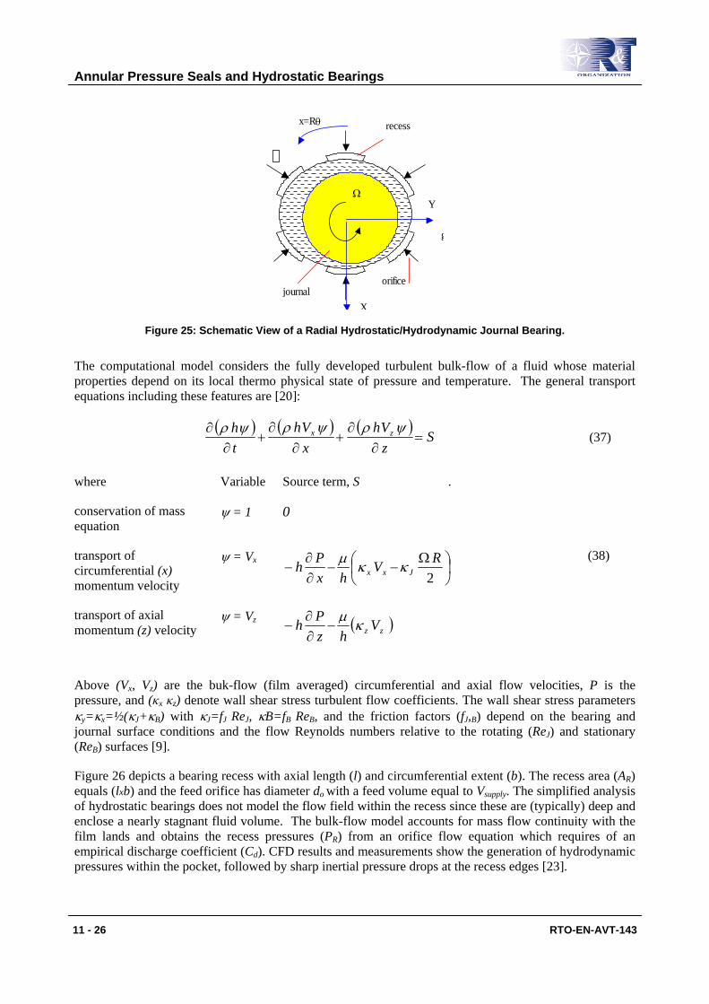
2.3 Bulk Flow Analysis of Turbulent Flow Hydrostatic Bearings Figure 25 shows the geometry of a hybrid (combination hydrostatic/hydrodynamic) journal bearing. A liquid at high pressure (Ps) is supplied through orifice restrictors and impinges into the bearing recesses with a mean pressure (PR). The fluid injection is typically radial; though in some instances it could be at an angle opposing shaft rotation3. The pressure field within the recesses is determined from flow continuity with the film lands, momentum exchange at the orifice plane and a viscous rise due to journal rotation. At the recess edges, an inertial pressure drop also occurs due to the sudden transition from the recess of depth (hR) into the film lands of thickness (h). Past the recesses, the liquid then flows through the film lands and the pressure drops to the discharge value (Pa).
3 Angled injection aids to reduce the development of circumferential flow speed and reduce, even eliminate, the magnitude of
cross-coupled stiffness coefficients [28].
Annular Pressure Seals and Hydrostatic Bearings
11 - 26 RTO-EN-AVT-143
x=Rθ
X
Y
recess
orificejournal
Ω
g
Figure 25: Schematic View of a Radial Hydrostatic/Hydrodynamic Journal Bearing.
The computational model considers the fully developed turbulent bulk-flow of a fluid whose material properties depend on its local thermo physical state of pressure and temperature. The general transport equations including these features are [20]:
( ) ( ) ( )S
zVh
xVh
th zx =
∂∂
+∂
∂+
∂∂ ψρψρψρ
(37)
where Variable Source term, S .
conservation of mass equation
ψ = 1 0
transport of circumferential (x) momentum velocity
ψ = Vx
Ω
−−∂∂
−2RV
hxPh Jxx κκµ
(38)
transport of axial momentum (z) velocity
ψ = Vz ( )zz Vhz
Ph κµ−
∂∂
−
Above (Vx, Vz) are the buk-flow (film averaged) circumferential and axial flow velocities, P is the pressure, and (κx κz) denote wall shear stress turbulent flow coefficients. The wall shear stress parameters κy=κx=½(κJ+κB) with κJ=fJ ReJ, κB=fB ReB, and the friction factors (fJ,B) depend on the bearing and journal surface conditions and the flow Reynolds numbers relative to the rotating (ReJ) and stationary (ReB) surfaces [9].
Figure 26 depicts a bearing recess with axial length (l) and circumferential extent (b). The recess area (AR) equals (lxb) and the feed orifice has diameter do with a feed volume equal to Vsupply. The simplified analysis of hydrostatic bearings does not model the flow field within the recess since these are (typically) deep and enclose a nearly stagnant fluid volume. The bulk-flow model accounts for mass flow continuity with the film lands and obtains the recess pressures (PR) from an orifice flow equation which requires of an empirical discharge coefficient (Cd). CFD results and measurements show the generation of hydrodynamic pressures within the pocket, followed by sharp inertial pressure drops at the recess edges [23].

Annular Pressure Seals and Hydrostatic Bearings
RTO-EN-AVT-143 11 - 27
Supply pressure
Ps
−
+
R
R
P
P
Pa
PR
Film landFluid flow, MΓ
b H
MR
HR
Ps
PR, recess pressure
Feed orifice andSupply volume
Film land
ΩR b
Supply pressure
Ps
−
+
R
R
P
P
Pa
PR
Film landFluid flow, MΓ
b H
MR
HR
Ps
PR, recess pressure
Feed orifice andSupply volume
Film land
ΩR b
Figure 26: Turbulent Flow Pressure Distribution in a Pocket of a Hybrid Bearing.
The continuity equation at a hydrostatic recess establishes a balance among the mass flow through the feed orifice (MR), the flow through the boundaries of the recess into the film lands (MΓ), and the accumulation of fluid mass within the recess volume, VR=[AR (h+hR)+Vsupply]. That is,
[ ] ( )RRsodR V
tMPPACM ρρ
∂∂
+=
−= Γ
2/1
2 (39)
where Ao = Cd (πdo2/4) is the effective orifice area, and ( )∫
ΓΓ Γ⋅= dVhM ηρ is the outflow from the
pocket into the bearing film lands. The circumferential pressure downstream of the feed orifice, +RP , is
given, as in a Rayleigh step bearing, by [24]
( ) Rx
RxRR VR
hhbPP
−
Ω+
+=+
22 2κµ (40)
Fluid inertia causes a sudden pressure drop at the interface between a recess and the film lands. The fluid pressures, −
RP , entering into the film lands bounding a recess are
2,
2
12
)1(zx
Re
eRR V
hhhPP
+
−
++= +
−+−
ρρ
ρξ (41)
where (ξ) represents empirical entrance loss coefficients at the recess edges, axial and circumferential. The sudden pressure drop is accounted for only if the fluid flow effectively enters into the thin film lands.
Recall that severe sub synchronous vibrations at rotational speeds above a certain threshold denote a hydrodynamic instability on rotor-fluid film bearing systems and due to the effect of journal rotational speed on the shear flow field. This condition is typical of fixed geometry bearings. The threshold speed corresponds to the rotor speed at which a bearing is deprived from its effective damping and any small perturbation from an equilibrium position will determine unbounded rotor motions. The whirl frequency ratio (WFR) denotes the ratio between the onset whirl frequency (typically the system first critical speed) and the threshold speed of instability. Plain journal bearings show a WFR equal to 0.50 for small to

Annular Pressure Seals and Hydrostatic Bearings
11 - 28 RTO-EN-AVT-143
moderate operating eccentricities (light loads), and thus instability onsets at rotational speeds equal to twice the system first critical speed. Measurements in hybrid bearings verify closely the prediction of WFR =0.50 [27]. In some circumstances the WFR even increases above 0.50, in particular for low rotational speeds and large supply pressures.
San Andrés [28] extends the bulk-flow model to account for fluid injection at an angle and opposing shaft rotation. This design feature retards the full development of the circumferential flow velocity, thus reducing the cross-coupled stiffness coefficients which prevent the operation of hybrid bearings at large rotational speeds.
2.4 Hydrostatic Bearings for Load Support in a Water Pump This section presents process fluid hydrostatic bearings designed to replace mineral oil lubricated bearings in a multiple stage water pump. The hydrostatic bearing size, length and diameter, must be similar to the original bearings to reduce costs in redesigning or re-machining the pump casing. Eliminating the lubrication system offers distinct advantages, including better performance, lower operational cost and extended periods for maintenance.
The pump nominal operating speed is 3,600 rpm with a pressure discharge of 34.4 bars. The pressurized water feeding the hydrostatic bearings is routed from the pump discharge pipe. In the application, the static load acting on each bearing equals 5 kN (1,125 lb). Table 2 presents the hydrostatic bearing dimensions. The pressurized fluid for the hydrostatic bearings is routed from the pump discharge volute. Thus, the liquid pressure supply into the bearings varies in a quadratic form with rotor speed, ∆P ~ Ω2. The speed range for predictions is 1,000 to 5,000 rpm.
Table 2: Geometry and Operating Conditions of Hydrostatic Bearings for a Liquid Pump
D=L = 152. 4 mm c=0.102 mm, nominal clearance
5 pockets: l=51 mm, arc 41° , depth=0.381 mm Orifice diameter: 3.2 mm (Cd=0.80) Smooth bearing and rotor surfaces
Fluid: water at 30°C ( 0.792 cPoise, 995 kg/m3) Nominal speed = 3600 rpm, Supply pressure= 34.4 bar
Static load = 5000 N
Note that for the bearing studied, L/D=1, D/c=1,465. The clearance selected is 1.33 times larger than that of the original oil-lubricated bearing. The ratio of pocket area to bearing area, L x D, equals 0.19, and the pocket depth to clearance ratio is 3.75. The pocket area is relatively small to avoid excessive flow rate requirements. The pockets are shallow to reduce the likelihood of pneumatic hammer effects and enhance hydrodynamic effects at the pocket end in the circumferential direction. Hydrostatic bearings with reduced pocket areas (< 25% of bearing area) and shallow pockets are modern considerations relying on the desired adequate dynamic forced performance of the bearing [20, 25].
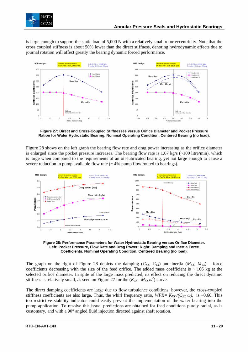
At the nominal speed of operation, the size of the orifice is selected to provide the maximum direct (support) stiffness while keeping in mind the need of low flow rates to avoid an excessive penalty on pump operation. The design analysis is conducted with the bearings operating without applied load at their centered position, i.e. null eccentricity. Figure 27 depicts the stiffness coefficients, direct (KXX) and cross-coupled (KXY), versus the orifice diameter on the left graph, and versus the calculated pocket pressure ratio on the right graph. The direct stiffness peaks at a pocket pressure ratio ~ 0.60 which requires an orifice of diameter equal to 3.20 mm. The magnitude of direct stiffness equals 350 MN/m, i.e. 350N/micron, which
Annular Pressure Seals and Hydrostatic Bearings
RTO-EN-AVT-143 11 - 29
is large enough to support the static load of 5,000 N with a relatively small rotor eccentricity. Note that the cross coupled stiffness is about 50% lower than the direct stiffness, denoting hydrodynamic effects due to journal rotation will affect greatly the bearing dynamic forced performance.
0
50
100
150
200
250
300
350
400
2 2.5 3 3.5 4 4.5 5 5.5Orifice diameter (mm)
Stiff
ness
coe
ffici
ents
Kxx (MN/m)Kxy (MN/m)
L=D=0.152 m, c=102 um, 5 pocket (l=L/3, arc =42 deg)
At nominal operating condition
Ps-Pa=34.4 bar, 3600 rpmHJB design:
Kxx = Kyy
Kxy = -Kyx
3.20 mmSelected orifice diameter
0
50
100
150
200
250
300
350
400
0.2 0.3 0.4 0.5 0.6 0.7 0.8 0.9 1Pocket pressure ratio
Stiff
ness
coe
ffici
ents
Kxx (MN/m)Kxy (MN/m)Kxx-Mxx w^2
L=D=0.152 m, c=102 um, 5 pocket (l=L/3, arc =42 deg)
At nominal operating condition
Ps-Pa=34.4 bar, 3600 rpmHJB design:
Kxx = Kyy
Kxy = -Kyx
3.20 mmSelected orifice diameter
Kxx - Mxx ω2
Figure 27: Direct and Cross-Coupled Stiffnesses versus Orifice Diameter and Pocket Pressure Ration for Water Hydrostatic Bearing. Nominal Operating Condition, Centered Bearing (no load).
Figure 28 shows on the left graph the bearing flow rate and drag power increasing as the orifice diameter is enlarged since the pocket pressure increases. The bearing flow rate is 1.67 kg/s (~100 litre/min), which is large when compared to the requirements of an oil-lubricated bearing, yet not large enough to cause a severe reduction in pump available flow rate (~ 4% pump flow routed to bearings).
0.0
0.5
1.0
1.5
2.0
2.5
3.0
3.5
2 2.5 3 3.5 4 4.5 5 5.5Orifice diameter (mm)
Para
met
ers Pocket pressure ratio
HJB flow rate (kg/s)Power (kw)
L=D=0.152 m, c=102 um, 5 pocket (l=L/3, arc =42 deg)
At nominal operating condition
Ps-Pa=34.4 bar, 3600 rpmHJB design:
Flow rate (kg/s)
Drag power (kW)
Pocket pressure ratio
selected orifice diameter
Supply pressure
0
100
200
300
400
500
600
700
800
900
1000
2 2.5 3 3.5 4 4.5 5 5.5
Orifice diameter (mm)
Para
met
ers
Mxx (kg)Mxy (kg)Cxx (kNs/m)Cxy (kNs/m)
L=D=0.152 m, c=102 um, 5 pocket (l=L/3, arc =42 deg)
At nominal operating condition
Ps-Pa=34.4 bar, 3600 rpmHJB design:
Cxx = Cyy
Mxx = Myy
Cxy = CyxMxy = -Myx
selected design
Figure 28: Performance Parameters for Water Hydrostatic Bearing versus Orifice Diameter. Left: Pocket Pressure, Flow Rate and Drag Power; Right: Damping and Inertia Force
Coefficients. Nominal Operating Condition, Centered Bearing (no load).
The graph on the right of Figure 28 depicts the damping (CXX, CYX) and inertia (MXX, MYX) force coefficients decreasing with the size of the feed orifice. The added mass coefficient is ~ 166 kg at the selected orifice diameter. In spite of the large mass predicted, its effect on reducing the direct dynamic stiffness is relatively small, as seen on Figure 27 for the (KXX - MXX ω2) curve.
The direct damping coefficients are large due to flow turbulence conditions; however, the cross-coupled stiffness coefficients are also large. Thus, the whirl frequency ratio, WFR= KXY /(CXX ω), is ~0.60. This too restrictive stability indicator could easily prevent the implementation of the water bearing into the pump application. To resolve this issue, predictions are obtained for feed conditions purely radial, as is customary, and with a 90° angled fluid injection directed against shaft rotation.

Annular Pressure Seals and Hydrostatic Bearings
11 - 30 RTO-EN-AVT-143
In the following, the performance, static and dynamic, of the water hydrostatic bearing is shown for the cases of radial injection and tangential injection. The predictions were obtained for the full static load condition, 5 kN, as the rotor speed increases from 1 krpm to 5 krpm. The orifice diameter selected is 3.2 mm.
Journal Eccentricity and Attitude Angle: Figure 29 displays the journal eccentricity (e/c) and attitude angle for the water HJB with radial and angled injection. At the nominal operating condition (3,600 rpm), the rotor eccentricity is just 11% of the bearing clearance. Angled injection has a pronounced effect on the attitude angle. Small values of attitude angle indicate a rotor displacement parallel to the applied load. This is a desired condition that will reduce the magnitude of the cross-coupled stiffness coefficients. Note that for low speeds, less than 2000 rpm, when the pump has not yet generated enough head (pressure), the journal eccentricity exceeds 50% of the bearing clearance. At low shaft speeds, hydrodynamic effects are of greatest importance to support the applied external load. Since water has a low viscosity, it is quite likely that the bearing surfaces need to be coated with a solid lubricant able to withstand short periods of rotor to bearing contact while the pump rotor accelerates to its design operating point.
Operating journal eccentricity
0.00
0.10
0.20
0.30
0.40
0.50
0.60
0.70
0.80
0.90
1.00
0 1000 2000 3000 4000 5000 6000
Rotor Speed (RPM)
tangential injection
radial injection
[fraction of clearance]
operating condition, Ps-Pa=34.4 bar
STATIC LOAD = 5 kN
L=D=0.152 m, c=102 um, 5 pocket (l=L/3, arc =42 deg), orifice do=3.2 mm Attitude angle
0
5
10
15
20
25
30
35
40
0 1000 2000 3000 4000 5000 6000
Rotor Speed (RPM)
tangential injection
radial injection
[deg] operating condition, Ps-Pa=34.4 bar
STATIC LOAD = 5 kN
x
y
L=D=0.152 m, c=102 um, 5 pocket (l=L/3, arc =42 deg), orifice do=3.2 mm
load direction
Figure 29: Journal Eccentricity and Attitude Angle versus Rotor Speed.
Water Hydrostatic Bearing with Radial and Tangential Injections. Load (X)=5 kN.
Film Pressures and Flow Rate: Figure 30 presents the film pocket pressure and flow rate as rotor speed increases. The left graph includes the supply pressure into the bearings. The pocket pressures follow the growth in feed pressure; tangential injection generating slightly larger magnitudes. Radial and angled injections produce very similar flow rates. Note that the flow rate varies linearly with shaft speed since the feed pressure and pocket pressures are proportional to the second power of speed; i.e. flow rate ~ ∆P1/2 ~ Ω.
Max film pressures
0.0
10.0
20.0
30.0
40.0
50.0
60.0
70.0
80.0
0 1000 2000 3000 4000 5000 6000
Rotor Speed (RPM)
tangential injection
radial injection
Supply pressure
[bar] operating condition, Ps-Pa=34.4 bar supply pressure function of pump speed
STATIC LOAD = 5 kN
L=D=0.152 m, c=102 um, 5 pocket (l=L/3, arc =42 deg), orifice do=3.2 mm
Mass flow rate
0.00
0.50
1.00
1.50
2.00
2.50
3.00
0 1000 2000 3000 4000 5000 6000
Rotor Speed (RPM)
tangential injection
radial injection
[kg/s] operating condition, Ps-Pa=34.4 bar
STATIC LOAD = 5 kN
L=D=0.152 m, c=102 um, 5 pocket (l=L/3, arc =42 deg), orifice do=3.2 mm
Figure 30: Maximum Film Pressures and Flow Rate versus Rotor Speed.
Water Hydrostatic Bearing with Radial and Tangential Injections. Load (X)=5 kN.

Annular Pressure Seals and Hydrostatic Bearings
RTO-EN-AVT-143 11 - 31
Torque and Drag Power: Figure 31 shows the drive torque and drag power for the water hybrid bearings. Angled injection causes a net reduction in torque and power since the average circumferential flow speed is reduced. The drag power is not large; its magnitude is certainly a fraction of that required in an oil lubricated bearing.
Drag Torque
0.00
2.00
4.00
6.00
8.00
10.00
12.00
14.00
16.00
0 1000 2000 3000 4000 5000 6000
Rotor Speed (RPM)
tangential injection
radial injection
[N-m] operating condition, Ps-Pa=34.4 bar
STATIC LOAD = 5 kN
L=D=0.152 m, c=102 um, 5 pocket (l=L/3, arc =42 deg), orifice do=3.2 mm Drag Power
0.00
1.00
2.00
3.00
4.00
5.00
6.00
7.00
8.00
0 1000 2000 3000 4000 5000 6000
Rotor Speed (RPM)
tangential injection
radial injection
[kW] operating condition, Ps-Pa=34.4 bar
L=D=0.152 m, c=102 um, 5 pocket (l=L/3, arc =42 deg), orifice do=3.2 mm
STATIC LOAD = 5 kN
Figure 31: Torque and Drag Power versus Rotor Speed. Water Hydrostatic Bearing with Radial and Tangential Injections. Load (X)=5 kN.
Stiffnesses Coefficients: Figure 32 depicts the direct stiffnesses, KXX and KYY, increasing rapidly with rotor speed, i.e. with supply pressure. Angled liquid injection does not affect the generation of direct stiffnesses. The cross-coupled stiffnesses, KXY and KYX, also increase with rotor speed due to enhanced hydrodynamic effects. However, tangential fluid injection aids to reduce dramatically the cross-coupled coefficients; thus contributing to the rotor dynamic stability of the water hydrostatic bearing.
The large stiffness coefficients at the lowest shaft speed are to be taken with caution. At this speed the bearing is not supplied with enough pressurized water to warrant support of the applied load with a full film condition. The coefficients shown demonstrate the paramount effect of shear driven flow, i.e. hydrodynamic effects generated by shaft rotation and minute film thicknesses (large operating eccentricity).
Direct stiffnesses
0
100
200
300
400
500
600
700
800
900
0 1000 2000 3000 4000 5000 6000
Rotor Speed (RPM)
Kxx: tangential injection radial injectionKyy tangential injection radial injection
[MN/m] operating condition, Ps-Pa=34.4 bar
STATIC LOAD = 5 kN
x
y
Kxx, Kyy L=D=0.152 m, c=102 um, 5 pocket (l=L/3, arc =42 deg), orifice do=3.2 mm Cross stiffnesses
-200
-100
0
100
200
300
400
500
600
700
800
0 1000 2000 3000 4000 5000 6000
Rotor Speed (RPM)
Kxy: tangential injection radial injection-Kyx tangential injection radial injection
[MN/m] operating condition, Ps-Pa=34.4 bar
STATIC LOAD = 5 kN
x
y
tangentialinjection
Kxy, -Kyx
radialinjection
L=D=0.152 m, c=102 um, 5 pocket (l=L/3, arc =42 deg), orifice do=3.2 mm
Figure 32: Stiffness Coefficients versus Rotor Speed. Water Hydrostatic Bearing with Radial and Tangential Injections. Load (X)=5 kN.
At the nominal operating condition (3,600 rpm) the direct stiffnesses are large in magnitude, ~ 350 N/micron; therefore the small operating journal eccentricity for the applied load of 5 kN. Bearing direct stiffnesses have a pronounced effect on the natural frequencies and mode shapes of a rotor-bearing system.

Annular Pressure Seals and Hydrostatic Bearings
11 - 32 RTO-EN-AVT-143
In rotating machinery with long shaft spans and incorporating hydrostatic bearings with large feed pressures, the first natural mode of vibration will be a low frequency - bending mode with nodes close to the bearing supports, i.e. a pin-pin mode elastic mode shape.
Damping Coefficients: Figure 33 shows the direct (CXX, CYY) and cross-coupled (CXY, -CYX) damping coefficients versus shaft speed. Note the scale difference in the graphs for direct and cross-coefficients. CXY , -CYX < CXX , CYY. Angled fluid injection affects the cross-damping coefficients only. At low speeds, the large values of damping denote a purely hydrodynamic operation lacking enough external pressurization.
Direct damping
0
500
1000
1500
2000
2500
3000
0 1000 2000 3000 4000 5000 6000
Rotor Speed (RPM)
Cxx: tangential injection radial injectionCyy tangential injection radial injection
[kNs/m] operating condition, Ps-Pa=34.4 bar
STATIC LOAD = 5 kN
x
y
Cxx, CyyL=D=0.152 m, c=102 um, 5 pocket (l=L/3, arc =42 deg), orifice do=3.2 mm Cross damping
0
50
100
150
200
250
300
0 1000 2000 3000 4000 5000 6000
Rotor Speed (RPM)
Cxy: tangential injection radial injection-Cyx tangential injection radial injection
[kNs/m] operating condition, Ps-Pa=34.4 bar
STATIC LOAD = 5 kN
x
ytangentialinjection
Cxy, -Cyx
radialinjection
L=D=0.152 m, c=102 um, 5 pocket (l=L/3, arc =42 deg), orifice do=3.2 mm
Figure 33: Damping Coefficients versus Rotor Speed. Water Hydrostatic Bearing with Radial and Tangential Injections. Load (X)=5 kN.
Inertia Coefficients: Figure 34 depicts the direct (MXX, MYY) and cross-coupled (MXY, -MYX) inertia coefficients as shaft speed increases. Note that the vertical scale in both graphs is not the same. MXY, -MYX < MXX , MYY. Angled fluid injection has an effect on the cross-inertia coefficients. Most importantly, note that the direct added mass coefficients are practically invariant with shaft speed.
Direct inertia
0
20
40
60
80
100
120
140
160
180
200
0 1000 2000 3000 4000 5000 6000
Rotor Speed (RPM)
Mxx: tangential injection radial injectionMyy tangential injection radial injection
[kg]
operating condition, Ps-Pa=34.4 bar
STATIC LOAD = 5 kN
x
y
Mxx, Myy L=D=0.152 m, c=102 um, 5 pocket (l=L/3, arc =42 deg), orifice do=3.2 mm Cross-inertia
0
5
10
15
20
25
0 1000 2000 3000 4000 5000 6000
Rotor Speed (RPM)
Mxy: tangential injection radial injection+Myx tangential injection -Mxy radial injection
[kg] operating condition, Ps-Pa=34.4 bar
STATIC LOAD = 5 kN
x
y
Mxy, -MyxL=D=0.152 m, c=102 um, 5 pocket (l=L/3, arc =42 deg), orifice do=3.2 mm
Figure 34: Inertia Coefficients versus Rotor Speed. Water Hydrostatic Bearing with Radial and Tangential Injections. Load (X)=5 kN.
The mass of water contained within the bearing is just a few grams; yet the predicted direct added mass coefficients are orders of magnitude larger than the physical mass of fluid, MXX~ MYY ~ 160 kg. For the bearing studied, a piece of solid steel shaft, length and diameter equalling 0.152 m, has a mass of just 21.7 kg. Thus, bearing fluid inertia coefficients must be included in a proper rotordynamic analysis of the rotor-bearing system.
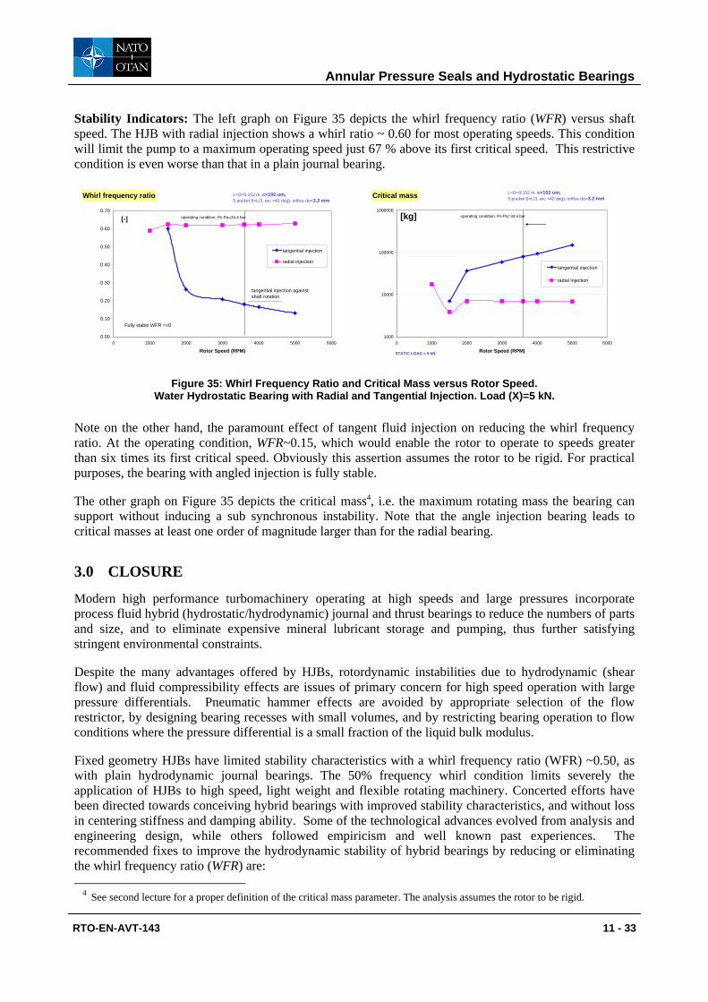
Annular Pressure Seals and Hydrostatic Bearings
RTO-EN-AVT-143 11 - 33
Stability Indicators: The left graph on Figure 35 depicts the whirl frequency ratio (WFR) versus shaft speed. The HJB with radial injection shows a whirl ratio ~ 0.60 for most operating speeds. This condition will limit the pump to a maximum operating speed just 67 % above its first critical speed. This restrictive condition is even worse than that in a plain journal bearing.
Whirl frequency ratio
0.00
0.10
0.20
0.30
0.40
0.50
0.60
0.70
0 1000 2000 3000 4000 5000 6000
Rotor Speed (RPM)
tangential injection
radial injection
[-] operating condition, Ps-Pa=34.4 bar
tangential injection against shaft rotation
L=D=0.152 m, c=102 um, 5 pocket (l=L/3, arc =42 deg), orifice do=3.2 mm
Fully stable WFR =<0
Critical mass
1000
10000
100000
1000000
0 1000 2000 3000 4000 5000 6000
Rotor Speed (RPM)
tangential injection
radial injection
[kg] operating condition, Ps-Pa=34.4 bar
STATIC LOAD = 5 kN
L=D=0.152 m, c=102 um, 5 pocket (l=L/3, arc =42 deg), orifice do=3.2 mm
Figure 35: Whirl Frequency Ratio and Critical Mass versus Rotor Speed.
Water Hydrostatic Bearing with Radial and Tangential Injection. Load (X)=5 kN.
Note on the other hand, the paramount effect of tangent fluid injection on reducing the whirl frequency ratio. At the operating condition, WFR~0.15, which would enable the rotor to operate to speeds greater than six times its first critical speed. Obviously this assertion assumes the rotor to be rigid. For practical purposes, the bearing with angled injection is fully stable.
The other graph on Figure 35 depicts the critical mass4, i.e. the maximum rotating mass the bearing can support without inducing a sub synchronous instability. Note that the angle injection bearing leads to critical masses at least one order of magnitude larger than for the radial bearing.
3.0 CLOSURE
Modern high performance turbomachinery operating at high speeds and large pressures incorporate process fluid hybrid (hydrostatic/hydrodynamic) journal and thrust bearings to reduce the numbers of parts and size, and to eliminate expensive mineral lubricant storage and pumping, thus further satisfying stringent environmental constraints.
Despite the many advantages offered by HJBs, rotordynamic instabilities due to hydrodynamic (shear flow) and fluid compressibility effects are issues of primary concern for high speed operation with large pressure differentials. Pneumatic hammer effects are avoided by appropriate selection of the flow restrictor, by designing bearing recesses with small volumes, and by restricting bearing operation to flow conditions where the pressure differential is a small fraction of the liquid bulk modulus.
Fixed geometry HJBs have limited stability characteristics with a whirl frequency ratio (WFR) ~0.50, as with plain hydrodynamic journal bearings. The 50% frequency whirl condition limits severely the application of HJBs to high speed, light weight and flexible rotating machinery. Concerted efforts have been directed towards conceiving hybrid bearings with improved stability characteristics, and without loss in centering stiffness and damping ability. Some of the technological advances evolved from analysis and engineering design, while others followed empiricism and well known past experiences. The recommended fixes to improve the hydrodynamic stability of hybrid bearings by reducing or eliminating the whirl frequency ratio (WFR) are:
4 See second lecture for a proper definition of the critical mass parameter. The analysis assumes the rotor to be rigid.
Annular Pressure Seals and Hydrostatic Bearings
11 - 34 RTO-EN-AVT-143
a) Use textured bearing surfaces to decrease the cross-coupled stiffness coefficients. Test results with a knurled-pattern HJB show a WFR as low as 0.30 but with a reduced load capacity and direct stiffness when compared to a smooth surface HJB [27].
c) Use angled liquid injection opposing journal rotation to reduce the development of the circumferential flow velocity leading to a virtual elimination of cross-coupled stiffness coefficients [28]. The example studied evidences the advantages of angled injection in a process fluid hybrid bearing for a water pump. Measurements conducted on a five-pocket water HJB verify the analysis, demonstrating that angled injection aids in reducing the whirl frequency ratio without decreasing the bearing centering stiffness and load capacity. However, the effectiveness of angled injection is reduced as shaft speed increases towards high values where shear flow driven effects overcome the hydrostatic effect.
d) Introduce geometrical changes in the bearing to induce a stiffness orthotropy; for example circumferentially asymmetric grooved bearings can produce large anisotropy on the rotordynamic force coefficients [29]. This design enhances stability by rendering a lower direct stiffness in the plane of the axial grooves as compared to the orthogonal stiffness. Measurements have demonstrated the enhancement in performance.
b) Use flexure pivot-tilting pad HJBs [25], as depicted in Figure 35. These bearings are mechanically complex though nearly free of instabilities, i.e. the pads support flexibility eliminates the generation of cross-coupled stiffness coefficients. This type of bearing with air as the lubricant has shown tremendous potential for ready implementation in high-speed microturbomachinery [30].
Extensive analytical and experimental research has brought forward the technology of hybrid journal bearings (HJBs) for advanced turbo pump applications. Computational analyses including flow turbulence, fluid inertia and compressibility and thermal effects are available to bearing designers and rotordynamics engineers. The analyses have been validated by careful experimentation with measurements of load, leakage and torque, and identification of rotordynamic force coefficients.
REFERENCES
[1] Turbomachinery Rotordynamics, (chapter 4), D. Childs, John Wiley & Sons, Inc., 1993.
[2] Damping Seals for Turbomachinery, G. von Pragenau, NASA Technical Paper No. 1987, 1982.
[3] Annular Gas Seals and Rotordynamics of Compressors and Turbines, D. Childs & J. Vance, Proc. Of the 26th Turbomachinery Symposium, TAMU, pp. 201-220, 1997.
[4] Pump Rotordynamics made Simple, M. Carbo & S. Malanoski, Proc. Of the 15th International Pump Users Symposium, TAMU, pp. 167-203, 1998.
[5] Effects of Hydraulic Forces on Annular Pressure Seals on the Vibrations of Centrifugal Pump Rotors, H. Black, Journal of Mechanical Engineering Science, 11(2), pp. 206-213.
[6] Analysis of Variable Fluid Properties, Turbulent Annular Seals, L. San Andrés, ASME Journal of Tribology, 113, pp. 694-702, 1991.
[7] Advances in Mechanical Sealing – An Introduction to API 682 Second Edition, M. Huebner, J. Thorp, C. Buck & C. Fernandez, Proc. Of the 19th International Pump Users Symposium, TAMU, 2004.
[8] Introduction to Annular Pressure (Damper) Seals, L. San Andrés, Lecture Notes (#11) in Modern Lubrication, http://phn.tamu.edu/TRIBGroup, 2002.
Annular Pressure Seals and Hydrostatic Bearings
RTO-EN-AVT-143 11 - 35
[9] A Bulk-Flow Theory for Turbulence in Lubricant Films, G.G. Hirs, ASME Journal of Lubrication Technology, 94, pp. 137-146. 1973.
[10] Effect of Shaft Misalignment on the Dynamic Force Response of Annular Pressure Seals, L. San Andrés, STLE Tribology Transactions, 36, 2, pp. 173-182, 1993.
[11] Thermal Effects in Cryogenic Liquid Annular Seals, I: Theory and Approximate Solutions, L. San Andrés, Z. Yang & D. Childs, ASME Journal of Tribology, 115, 2, pp. 267-276, 1993.
[12] Thermal Effects in Cryogenic Liquid Annular Seals, II: Numerical Solution and Results, Z. Yang, L. San Andrés & D. Childs, ASME Journal of Tribology, 115, 2, pp.277-284, 1993.
[13] Analysis of Two Phase Flow in Cryogenic Damper Seals, I: Theoretical Model, II: Model Validation and Predictions, G. Arauz & L. San Andrés, “ASME Journal of Tribology, 120, pp. 221-233, 1998.
[14] Squeeze Film Dampers: Operation, Models and Technical Issues, L. San Andrés, Lecture Notes (#13) in Modern Lubrication, http://phn.tamu.edu/TRIBGroup, 2002.
[15] Gas Damper Seal Test Results, Theoretical Correlation, and Applications in Design of High-Pressure Compressors, P. De Choudhury, F. Kushner & J. Li, Proc. Of the 29th Turbomachinery Symposium, TAMU, 2001.
[16] Introduction to Hydrostatic Bearings, L. San Andrés, Lecture Notes (#12) in Modern Lubrication, http://phn.tamu.edu/TRIBGroup, 2002.
[17] Determination of the Discharge Coefficient of a Thin-Walled Orifice Used in Hydrostatic Bearings, S. Charles, O. Bonneau & J. Frene,” ASME Journal of Tribology, 127, pp. 679-684.
[18] Turbulent Hybrid Bearings with Fluid Inertia Effects, L. San Andrés, ASME Journal of Tribology, 112, pp. 699-707, 1990.
[19] Fluid Compressibility Effects on the Dynamic Response of Hydrostatic Journal Bearings, L. San Andrés, WEAR, 146, pp. 269-283, 1991.
[20] Thermohydrodynamic Analysis of Fluid Film Bearings for Cryogenic Applications, L. San Andrés, AIAA Journal of Propulsion and Power, 11, 5, pp. 964-972, 1995.
[21] Bulk Flow Analysis of Hybrid Thrust Bearings for Process Fluid Applications, L. San Andrés, ASME Journal of Tribology, 122, 1, pp. 170-180, 2000.
[22] Design and Development of an Advanced Liquid Hydrogen Turbopump, A. Minck & S. Peery, AIAA 98-3681, 34th ASAA/ASME/SAE/ASEE Joint propulsion Conference & Exhibit, 1998.
[23] Analysis of Turbulent Hydrostatic Bearings with a Barotropic Fluid, L. San Andrés, ASME Journal of Tribology, 114, 4,pp. 755-765,1992.
[24] Thermohydrodynamic Analysis of Process Liquid Hydrostatic Bearings in Turbulent Regime, I: The Model and Perturbation Analysis, II: Numerical Solution and Results, Z. Yang, L. San Andrés & D. Childs, ASME Journal of Applied Mechanics, 62, 3, pp. 674-679, pp. 680-684, 1995.
[25] Turbulent Flow, Flexure-Pivot Hybrid Bearings for Cryogenic Applications," ASME Journal of Tribology, 118, 1, pp. 190-200, 1996.
Annular Pressure Seals and Hydrostatic Bearings
11 - 36 RTO-EN-AVT-143
[26] Experimental versus Theoretical Characteristics of a High Speed Hybrid (combination Hydrostatic and Hydrodynamic) Bearing, K. Kurtin, D. Childs, D., L. San Andrés, & K. Hale, ASME Journal of Tribology, 115, 1, pp. 160-169, 1993.
[27] Theoretical and Experimental Comparisons for Rotordynamic Coefficients of a High-Speed, High-Pressure, Orifice-Compensated Hybrid Bearings," N. Franchek, D. Childs & L. San Andrés, ASME Journal of Tribology, 117, 2, pp. 285-290, 1995.
[28] Angled Injection - Hydrostatic Bearings, Analysis and Comparison to Test Results, L. San Andrés & D. Childs, ASME Journal of Tribology, 119, 1, pp. 179-187, 1997.
[29] A Hybrid Bearing with Improved Rotordynamic Stability,” L. San Andrés, L., 1st International Conference in Rotordynamics of Machinery, ISCORMA1, Paper 2006, 2001.
[30] Rotordynamic Performance of Flexure Pivot Hydrostatic Gas Bearings for Oil-Free Turbomachinery, S. Zhu & L., San Andrés, ASME Paper GT 2004-53621, 2004.