ans president's special committee on the fukushima accident
TRANSCRIPT
American Nuclear Society555 N. Kensington AvenueLaGrange Park IL 60526LaGrange Park, IL 60526708-352-6611; www.ans.org
ANS President’s Special Committee on the Fukushima Accident –Report Summary
AESJ –ANS Technical Meeting, TokyoTokyoSunday, March 4, 2012A. Tokuhiro, Presenter
Message from the ANS President
We are here to honor you and to assure you of our support for you
The anniversary is an opportunity for us to share our support, ideas, The anniversary is an opportunity for us to share our support, ideas, knowledge and expertise
Fall down seven times; get up eight
To be able to teach one must learn And by learning one thing you can To be able to teach one must learn. And by learning one thing, you can know ten.
On behalf of the 11,600 members of the American On behalf of the 11,600 members of the American
Nuclear Society we are here to learn, support and
help you in this difficult time.

ANS President’s Committee, Fukushima Accident
The ANS Committee drew experts from industry, academia and the national labs, resulting in a unique diversity of perspectives.
Committee Members– Prof. Dale Klein, Ph.D., P.E. Committee Co-Chair and former USNRC Chairman. Prof. Dale Klein, Ph.D., P.E. Committee Co Chair and former USNRC Chairman.
Dr. Klein served more than eight years as a Presidential Appointee and currently serves as Associate Vice Chancellor for Research in the Office of Academic Affairs at the University of Texas System.
Prof Michael Corradini Ph D Committee Co Chair and Wisconsin Distinguished – Prof. Michael Corradini, Ph.D. Committee Co-Chair and Wisconsin Distinguished Professor at the University of Wisconsin. Dr. Corradini is also Chair of the Energy Institute faculty governance committee and the director of the college’s Wisconsin Institute of Nuclear Systems.
P f J B i Ph D Ch i S b i R l I – Prof. Jacopo Buongiorno, Ph.D. Chairman, Subcommittee on Regulatory Issues and Associate Professor of Nuclear Science and Engineering at the Massachusetts Institute of Technology.
ANS President’s Committee, Fukushima Accident
Committee Members
–Prof. Hisashi Ninokata, Ph.D. Professor, Research Laboratory for Nuclear Reactors, Tokyo Institute of Technology, Chairman, ANS Thermal Hydraulics Division and ANS Fellow.
D Mi h l R Ph D CHP Adj t F lt M b t V d bilt U i it d –Dr. Michael Ryan, Ph.D., CHP, Adjunct Faculty Member at Vanderbilt University and Texas A&M University and independent consultant in radiological sciences and health physics.
–Mr. Paul T. Dickman, Chairman, Subcommittee on Risk Communication and Senior , ,Policy Fellow with Argonne National Laboratory focusing on international nuclear energy, non-proliferation and national security policy.
–Prof. Akira Tokuhiro, Ph.D., Professor of Mechanical and Nuclear Engineering at the University of Idaho Subcommittee on Clean-Up and Risk Communicationthe University of Idaho. Subcommittee on Clean Up and Risk Communication.
–Dr. Craig D. Sawyer, Ph.D., Chairman Subcommittee on Accident Sequence Analysis. Dr. Sawyer, retired, has served as a consultant to companies such as Westinghouse and GE and has authored many papers on BWR design and characteristicscharacteristics.
–Mr. Amir Shahkarami, Chief Executive Officer of Exelon Nuclear Partners and Senior Vice President of Exelon Generation. Subcommittee on Clean-Up.
ANS President’s Committee, Fukushima Accident
President’s Special Committee on the Fukushima Accident (Colvin) Schedule: Issued March 8 2012Schedule: Issued March 8, 2012
ContentsI Background (not covered today)I. Background (not covered today)II. Accident AnalysisIII. Health PhysicsIV A id ClIV. Accident CleanupV. Safety Issues and RecommendationsVI. Societal Context for the Fukushima Dai-ichi AccidentVII. The Fukushima Dai-ichi Accident and ANSReferencesBibliographyg p yAcronyms, Abbreviations and DefinitionsCommittee and Subcommittee Members
Accident AnalysisAccident AnalysisDai-ichi, Overall
(from the report) II.D. What Happens When Disaster Strikes
Starting point…
1)Wh ff i d i AC d DC l b d SBO ? A 1)When off-site and on-site AC power and DC are lost, a beyond SBO starts? As noted above, this leaves only the following installed systems to cope with the loss of water supply to the RPV:
a) the isolation condenser systems in BWR/3s, such as Fukushima Daiichi U1
b) the RCIC systems in BWR/4s, such as Fukushima Daiichi Units 2 through b) the RCIC systems in BWR/4s, such as Fukushima Daiichi Units 2 through 5; in BWR/5s, such as Fukushima Daiichi Unit 6; and in BWR/6s
c) the HPCI systems in BWR/3s and in BWR/4s, such as Fukushima Daiichi Units 1 through 5Units 1 through 5.
2)In addition to the systems themselves, DC power and compressed nitrogen (or air) are needed to open and close valves and operate the control systems, as well as provide power for instrumentation that the operator needs in order to take appropriate actions.
Continued -2
1) IC is capable of maintaining core cooling & removing DH, but if there are leaks in the pressure boundary additional makeup there are leaks in the pressure boundary, additional makeup water is needed.
2) RCIC & HPCI are capable of adding more water than needed to ) p gmake up for the steam generated by DH & can handle additional small leaks.
3) D i RCIC/HPCI i R (P) ll d b SRV 3) During RCIC/HPCI system operation, Rx(P) controlled by SRV action, but the steam is exhausted to the SP inside containment, so eventually DH removal from the containment must be restored if the containment cannot be vented.
4) NPPs also have direct diesel-driven pumps as part of the fire protection s stem or the fle ibilit to connect fire tr cks to the protection system, or the flexibility to connect fire trucks to the installed piping leading to the RPV for water makeup.

Continued -3
1) Takes extra time to utilize these additional emergency resources, the RPV must be depressurized to a low-P for these typically LP-the RPV must be depressurized to a low P for these typically LPpumps to be able to inject. Thus manually open SRVs to lower the Rx(P). Manual opening of the SRVs requires DC power & N2.
2) Without water flow into the RPV, there is a period of 1 to 4 hours (depending on how long the reactor has been SD before the makeup stops) before the fuel becomes uncovered,; ~30 minutes makeup stops) before the fuel becomes uncovered,; 30 minutes after that, the fuel will start releasing H2 & heat from reaction, then melting.
3) Large size of SP means that containment would not reach its design pressure for ~15 hours. Thus, high priority should be given to assuring water makeup to the RPV; include assuring means to g p ; gdepressurize when necessary; use additional emergency pumps.
Continued -4
1) Containment vent design, with valves that need DC power & compressed air or N2 to operate, plus an in-line rupture disk (with a set-point > than air or N2 to operate, plus an in line rupture disk (with a set point than the containment design pressure) that cannot be bypassed, led to containment pressures well in excess of the design pressure because of delays. y
2) Most likely, H2 in the Rx Bldg was leaks in the containment due to the high pressure, and perhaps also high containment temperatures that could have led to deterioration of the major seals (drywell head cover and have led to deterioration of the major seals (drywell head cover, and equipment and personnel airlocks).
3) Another possible source could also have been leakage past containment isolation valves.

Continued -5
1) In U2 & U3, operators should be commended for keeping the RCIC and the HPCI systems operating as long as they did. HPCI systems operating as long as they did.
2) We note that many PRAs performed on BWRs have shown the dominant core melt scenario to be SBO with eventual failure of the RCIC/HPCI s stems tho ght to be in 8 ho rs beca se of a n mber of potential systems, thought to be in ~8 hours because of a number of potential failure mechanisms.
3) During this time, no attempt was made to prepare for depressurization of ) g , p p p pthe RPV until these systems failed, and because of DC power failures and issues with providing alternative compressed N2, depressurization to allow alternative water sources was delayed.
Accident AnalysisAccident AnalysisDaichi, Unit 1

F1, U1,1) After SCRAM & loss of AC power due to earthquake, both trains of the ICS were
started because of closure of the main steam isolation valves (MSIVs) and subsequent pressurization of the RPV pressurization of the RPV.
2) Operators determined that with both trains operating, Rx cooldown rate exceeded the technical specification rate of 55°C/hour (100°F/hour); thus ICS were shut do n b the operators down by the operators.
3) Subsequently, one train of ICS restarted , then stopped several times to control the Rx(P) & cool Rx. HPCI system was not started during this time period as the water level in the RPV was adequate.
4) After tsunami, there was major flooding. Loss of heat removal function, EDGs & DC batteries for both power and instrumentation (located in basement of the TB) were batteries for both power and instrumentation (located in basement of the TB) were also flooded & lost. All I&C needed became unavailable; in addition, the HPCI system was not able to operate because of the loss of DC power & because ICS shut down.
5) Several attempts made to open the steam supply and condensate return valves of ICS 5) Several attempts made to open the steam supply and condensate return valves of ICS. Some evidence that ICS was at least partially working, because of observed steam evolution from the shell side of HX. However, by 10:00 p.m., March 11, rising radiation levels were observed in RB & TB; indication that core damage was ; goccurring.
F1, U1 continued,1) At 12:49 a.m. on March 12, local measurements confirmed that the containment
pressure had exceeded the design pressure, which was further evidence of core damage and hydrogen production from (Zr) cladding metal water reactiondamage and hydrogen production from (Zr) cladding metal-water reaction.
2) Processes started to evacuate local residents & prepare the containment for venting, in accordance with the NPP emergency procedures.
3) Operators prepared to vent PCV, but trouble because the radiation level in RB high. At ~2:30 p.m. on March 12, a small decrease in the PCV(P)was actually confirmed which could have been due to leakage paths in the PCV that opened confirmed, which could have been due to leakage paths in the PCV that opened because of the PCV being at high pressure or because of the vent rupture disk opening.
) S b l 3 36 l i d i h f h i 4) Subsequently, at 3:36 p.m., H2 explosions occurred in the upper part of the Unit 1 RB. Source of H2 in RB is thought to be containment leakage due to the high containment pressures that occurred, which were well in excess of the design pressure.
Accident AnalysisAccident AnalysisDaichi, Unit 2
F1, U2,1) As with U1, SCRAM occurred & MSIVs closed after earthquake. The RCIC system
was manually started a couple of times and automatically tripped because of a high water level in the RPV high water level in the RPV.
2) After the tsunami, DC power was lost, just as in U1; thus HPCI system was lost. However, RCIC system operated for ~70 hours, because of the creativity of the NPP operators, particularly load shedding of nonessential DC power loads. In general, one should not expect the RCIC system to run much beyond 8 hours under SBO.
3) At 1:25 p.m., March 14, determined that RCIC system of U2 stopped because the Rx water level was decreasing & operators began to reduce the RPV pressure to be able to inject seawater into Rx using fire-extinguishing-system lines. be able to inject seawater into Rx using fire extinguishing system lines.
4) Problems depressurizing due to lack of electricity for the solenoid valves & pressurized N2 supply to force the valves open. These issues caused significant ti d l i hi i l h R (P) t ll l time delays in achieving a low-enough Rx(P) to allow low-pressure emergency pumps to add water to the RPV.
5) Thus fuel was uncovered while the RPV was without any water injection for ~6.5 ) y jhours. The fuel heated up, with H2 production.
F1, U2 continued,1) Longer term, the water level in the RPV has not recovered to higher than core
midplane, indicating a low-elevation leak in the RPV pressure boundary.
2) Containment pressure rise at first was much slower than should be expected if all DH is delivered to the SP; indication of leak in the containment boundary.
3) Wetwell venting line configuration had been completed by 11:00 a m on March 3) Wetwell venting line configuration had been completed by 11:00 a.m. on March 13, but the containment pressure had not reached the rupture disk set-point, so no venting occurred.
4) After core damage, the containment pressure increased more rapidly, probably because of H2 production. At 6:00 a.m. on March 15, an impulsive sound that was initially attributed to H2 explosion was confirmed near the suppression chamber f h i d l h i d d h lof the containment, and later, the containment pressure decreased sharply.
5) Not clear whether the designed vent path was ever in service; however, longer term, the containment pressure has remained low, around the level of term, the containment pressure has remained low, around the level of atmospheric pressure.
Accident AnalysisAccident AnalysisDaichi, Unit 3
F1, U3,The situation at U3 followed closely that of U2, except that the RCIC system ran for only 20+ hours. system ran for only 20 hours.
However, the DC power supply for the HPCI system was not damaged, so the HPCI system started & operated additional 15 hours. Operation of HPCI s stem apparentl red ced RPV(P) beca se of the steam cons mption b system apparently reduced RPV(P) because of the steam consumption by the HPCI turbine (seven times larger than that of the RCIC system).
After HPCI system stopped, the RPV re-pressurized. Depressurization of the y pp , p pRPV to allow low-pressure pumps to add water was not started for 7 hours, and the RPV did not receive any water for that time.
As with Unit 2 problems with power for the solenoid valves & pressurized As with Unit 2, problems with power for the solenoid valves & pressurized N2 needed for SRV operation. Water level decreased to below the fuel level, and significant core damage & H2 production occurred. Fire engines began alternative water injection (freshwater containing boron) into Rx at began alternative water injection (freshwater containing boron) into Rx at ~9:25 a.m. on March 13.
F1, U3 continued,Later, the injection was changed to seawater; however, the water level in the RPV never recovered as expected, indicating a leak in the RPV or the RPV never recovered as expected, indicating a leak in the RPV or attached piping.
As with Unit 2, the containment pressure rise from DH was slower than e pected indicating the presence of a leak In parallel ith RPV expected, indicating the presence of a leak. In parallel with RPV depressurization, containment venting to decrease the PCV pressure was begun. Because of trouble with the solenoid valves & pressurized N2 supply, vent operations had to be done several times vent operations had to be done several times.
Subsequently, at 11:01 a.m. on March 14, a H2 explosion occurred in the upper part of the RB. Source of H2 is thought to be from leaks in the containment boundary.
Accident AnalysisAccident AnalysisDaichi, Unit 4
F1, U4,The total AC power supply for Unit 4 also was lost because of the earthquake/tsunamiearthquake/tsunami
Thus functions of cooling and supplying water to the SFP were lost. The SFP temperature increased to 84°C (183°F) by 4:00 a.m. on March 14.
At ~6:00 a.m. on March 15, an explosion thought to be a H2 explosion occurred in RB, severely damaging part of the building.
At first thought to be from fuel uncovery heatup and H production At first, thought to be from fuel uncovery, heatup, and H2 production. Thus, over the next several days, several different schemes were used to add water—via helicopter, fire truck, and concrete pump truck. Both freshwater and seawater were used freshwater and seawater were used.
Later, photographs indicated that there was no overheat damage to fuel in the SFP, and the source of H2 traced to backflow through the standby gas treatment system ducting that shared a common piping at the NPP stack with Unit 3, whose containment was being vented.
Accident AnalysisAccident AnalysisDaichi, Units 5 & 6
F1, U5 & U6,1) Units 5 and 6 are slightly separated from Units 1 through 4 and
are at a higher elevation The earthquake disabled the off-site are at a higher elevation. The earthquake disabled the off site power, and the tsunami caused the loss of both EDGs of Unit 5 and two of the three EDGs of Unit 6.
2) However, one EDG of Unit 6 was air cooled (not dependent on cooling water) and was located at a higher elevation, so it was able to supply emergency AC power to both Units 5 and 6. able to supply emergency AC power to both Units 5 and 6.
3) The availability of AC power gave these units the ability to depressurize the reactors. So, it was possible to add water to the RPVs via the low-pressure condensate transfer pumps.
4) The residual heat removal (RHR) pumps were also not lost, so hen a temporar sea ater p mp as installed to allo transfer when a temporary seawater pump was installed to allow transfer
of heat to the ocean, it was possible to reach cold shutdown again in both Units 5 and 6. This was achieved by March 20.

Accident AnalysisAccident AnalysisSpent Fuel Pool
Spent Fuel Pool(SFP) - 1Spent Fuel Pool(SFP) 1Spent-Fuel Situation at Fukushima Daiichi NPS
Th id i h d d h f l i h U i 5 SFP h The evidence is that no damage occurred to the fuel in the Unit 5 SFP, the Unit 6 SFP, or the common SFP. The September 2011 supplemental report by the Japanese government to the International Atomic Energy Agency (IAEA) concl ded that it is most likel that ater le els in the Unit 1 thro gh Unit concluded that it is most likely that water levels in the Unit 1 through Unit 4 SFPs were recovered before any spent fuel was exposed and damaged [1].

Spent Fuel Pool(SFP) - 2Spent Fuel Pool(SFP) 2When the off-site power and all but one of the EDGs were lost at the NPS, normal cooling of the SFPs was lost. The available EDG restored cooling to the Unit 5 and g gUnit 6 SFPs before the temperature increased significantly. Power was also restored to the common SFP cooling system before its temperature increased significantly.
On March 12, a hydrogen explosion damaged the upper portion of the structure surrounding the refueling bay on Unit 1. While this explosion may have resulted in material falling into the SFP, there is no evidence that damage to the fuel g , goccurred. Beginning on March 31, a concrete pumping truck provided makeup inventory to the Unit 1 SFP. An alternative cooling water system has since been put in service for Unit 1. As of September, the SFP water in Unit 1 has been maintained t 35°C (95°F)at <35°C (95°F).
Adding water using existing Unit 2 SFP piping began on March 20 and was intermittent. An analysis of an April 16 sample of the water in the Unit 2 skimmer surge tank suggests that the spent fuel was not damaged. By May 31, a dedicated system incorporating a heat exchanger was in service. An alternative cooling system is in operation, and as of September, the SFP water in Unit 2 has been
i t i d t 35°C (95°F)maintained at <35°C (95°F).
Spent Fuel Pool(SFP) - 2Spent Fuel Pool(SFP) 2On March 14, a hydrogen explosion damaged the structure housing the Unit 3 refueling pool. Water spray by water cannon and water drops by helicopter started March 17. By March 27, a
t i t i t th l U f i ti SFP i i t t SFP concrete pump was pumping water into the pool. Use of existing SFP piping to restore SFP inventory began in late April. A video recording made in the Unit 3 SFP was released on June 16 that showed debris from the containment structure had fallen into the SFP, but did not confirm the structural integrity of the fuel racks. It is likely that no damage has occurred to the spent f l A f S t b th SFP t i U it 3 h b i t i d t 35°C (95°F)fuel. As of September, the SFP water in Unit 3 has been maintained at <35°C (95°F).
Because of the relatively high decay heat associated with the fuel in the Unit 4 SFP (all fuel had been removed from the Unit 4 RPV in December 2010), special concern was focused on this SFP, which was intensified when the refueling floor containment structure was severely damaged which was intensified when the refueling floor containment structure was severely damaged because of an apparent hydrogen explosion early in the morning of March 15. Initially, since the Unit 4 RPV was defueled, the source of the hydrogen was thought to be the stored used fuel, implying that SFP inventory had been lost early in the accident. Later, the source of the hydrogen was determined to likely be from Unit 3 via a pathway to the Unit 4 refueling floor leaking was determined to likely be from Unit 3, via a pathway to the Unit 4 refueling floor, leaking through a shared pipe to the stack.
Unit 4 SFP temperatures were reported to be 84°C (183°F) on March 14 and 15. Water was intermittently sprayed from trucks beginning March 20. Nevertheless, the reported SFP y p y g g ptemperature on March 24 was 100°C (212°F). Water was introduced to the SFP using concrete pumps starting March 25, which offered a more reliable method of delivering water to the SFP.

ANS Timeline of Events(next week)
FiguresFigures

Birdseye View Of Fukushima Dai-ichi NPPs (1F)
Cf. http://cryptome.org/eyeball/daiichi-npp2/daiichi-photos2.htm
GE BWR, Mark-I Nuclear Reactor
Some Accident Relevant Features
1) SECONDARY CONTAINMENT IS REALLY A CONFINEMENT
3) C O SS SS
2) SPENT FUEL POOL (SFP)
3) REACTOR PRESSURE VESSEL (BROWN)
4) TOROIDAL SUPPRESSION POOL (WETWELL)

GE BWR, Mark-I Nuclear Reactor
Some Accident Relevant Features
Mark I

Before and During the Tsunami
Photos: Reuters/TEPCO
Evacuation and Contamination
Contamination Map -‘Hot-Spots’Contamination Is Distributed Contamination Is Distributed
http://mdn.mainichi.jp/mdnnews/news/20110914p2a00m0na013000c.html

QUESTIONS?QUESTIONS?
REFERENCESREFERENCES

References 1[1] “Additional Report of the Japanese Government to the IAEA—The Accident at TEPCO’s Fukushima Nuclear Power Stations (Second Report),” Government of Japan, Nuclear Emergency Response Headquarters (September 2011).
[2] “Nuclear Radiation and Health Effects,” World Nuclear Association; http://www.world-nuclear.org/info/inf05.html (November 2011).
[3] “Assessment on the 66th Day of Projected External Doses for Populations Living in the North-[3] Assessment on the 66th Day of Projected External Doses for Populations Living in the NorthWest Fallout Zone of the Fukushima Nuclear Accident,” DRPH/2011-10, Institut de Radioprotection et de Sûreté Nucléaire (May 2011).
[4] “Evaluation of Environment Radiation Monitoring Results,” Nuclear Safety Commission of Japan; http://www.nsc.go.jp/NSCenglish/mnt/index.htm.
[5] “Progress Status of the ‘Roadmap for Immediate Actions for the Assistance of Residents Affected by the Nuclear Incident,’” Nuclear Emergency Response Headquarters, Ministry of Economy Trade and Industry; http://www meti go jp/english/earthquake/nuclear/roadmap/ Economy, Trade and Industry; http://www.meti.go.jp/english/earthquake/nuclear/roadmap/ (accessed September 20, 2011).
[6] “Regarding the Overview of Internal Exposures Survey on Fukushima Prefectural Residents Conducted by the National Institute of Radiological Sciences, July 28, 2011,” Nuclear and Conducted by the National Institute of Radiological Sciences, July 28, 2011, Nuclear and Industrial Safety Agency; http://www.nisa.meti.go.jp/english/press/index.html (accessed September 20, 2011).
[7] “The Nuclear Situation due to the Earthquake and Tsunami in Japan,” United Nations Scientific Committee on the Effects of Atomic Radiation; http://www.unscear.org/unscear/en/japan.html (accessed September 20, 2011).
References 2
[8] “The Situation in Japan (Updated 10/21/11): Radiological Assessment—of Effects from—Fukushima Daiichi Nuclear Power Plant,” U.S. Department of Energy, National Nuclear Security Administration; http://energy.gov/situation-japan-updated-102111. p
[9] T. J. YASUNARI et al., “Cesium-137 Deposition and Contamination of Japanese Soils due to the Fukushima Nuclear Accident,” PNAS, doi: 10.1073/pnas.1112058108; www.pnas.org/cgi/doi/10.1073/pnas.1112058108.
[10] “Information on the Great East Japan Earthquake,” Japanese Ministry of Health, Labor and Welfare; [ ] p q , p y , ;http://www.mhlw.go.jp/english/topics/2011eq/.
[11] “Measures Against Beef Which Exceeds the Provisional Regulation Values of Radioactive Cesium by the Government to Ensure Safety of Beef,” Government of Japan; http://www.kantei.go.jp/foreign/kan/topics/201107/measures beef.pdf.http://www.kantei.go.jp/foreign/kan/topics/201107/measures_beef.pdf.
[12] “Monitoring Information of Environmental Radioactivity Level,” Ministry of Education, Culture, Sports, Science and Technology–Japan; http://radioactivity.mext.go.jp/en/.
[13] “TEPCO News,” Tokyo Electric Power Company; http://www.tepco.co.jp/en/press/corp-com/release/index-e.html. [13] TEPCO News, Tokyo Electric Power Company; http://www.tepco.co.jp/en/press/corp com/release/index e.html.
[14] Code of Federal Regulations, Title 10, “Energy,” Part 50, “Domestic Licensing of Production and Utilization Facilities,” U.S. Nuclear Regulatory Commission.
[15] Code of Federal Regulations, Title 10, “Energy,” Part 50, “Domestic Licensing of Production and Utilization [15] Code of Federal Regulations, Title 10, Energy, Part 50, Domestic Licensing of Production and Utilization Facilities,” Sec. 150, “Aircraft Impact Assessment,” U.S. Nuclear Regulatory Commission.
[16] “Order for Interim Safeguards and Security Compensatory Measures,” EA-02-026, Sec. B.5.b, “Station Blackout and Advanced Accident Mitigation,” U.S. Nuclear Regulatory Commission; see also Code of Federal Regulations, Title 10, “Energy ” Part 50 “Domestic Licensing of Production and Utilization Facilities ” Sec 54 “Conditions of Licenses ” Energy, Part 50, Domestic Licensing of Production and Utilization Facilities, Sec. 54, Conditions of Licenses, U.S. Nuclear Regulatory Commission.

References 3
[17] “NRC Provides Protective Action Recommendations Based on U.S. Guidelines,” NRC News Release 11-050 (March 16, 2011).
[18] “E t E E t liti f E ” EUR 16520 EN E C i i (J l 1995) [18] “ExternE—Externalities of Energy,” EUR 16520 EN, European Commission (July 1995).
[19] “Unedited Fukushima Accident Manual Released, Loss of Power Sources Not Envisioned,” The Mainichi Daily News, October 25, 2011.
[20] N. ONISHI and J. GLANZ, “Japanese Rules for Nuclear Plants Relied on Old Science,” New York Times, March 26, 2011.
[21] N. ONISHI and M. FACKLER. “In Nuclear Crisis, Crippling Mistrust,” New York Times, June 12, 2011 2011.
[22] J. SOBLE, “Fukushima Teams ‘Prepared for Death,’” Financial Times, March 18, 2011.
[23] I. KHRIPUNOV, “What We Need to Know ... and When,” IAEA Bulletin, 48, 1, 39 (September 2006).
[24] F. P. CASTRONOVO, Jr., “Teratogen Update: Radiation and Chernobyl,” Teratology, 60, 2, 100 (1999).
[25] M. TUBIANA, L. E. FEINENDEGEN, C. YANG, and J. M. KAMINSKI, “The Linear No-Threshold R l i hi I I i i h R di i Bi l i d E i l D ” R di l 251 1 13 Relationship Is Inconsistent with Radiation Biologic and Experimental Data,” Radiology, 251, 1, 13 (April 2009).
[26] “Chernobyl’s Legacy: Health, Environmental and Socio-Economic Impacts and Recommendations to the Governments of Belarus, the Russian Federation and Ukraine (Second Revised Version),” The to the Governments of Belarus, the Russian Federation and Ukraine (Second Revised Version), The Chernobyl Forum: 2003–2005, International Atomic Energy Agency.
SPARE SLIDESSPARE SLIDES
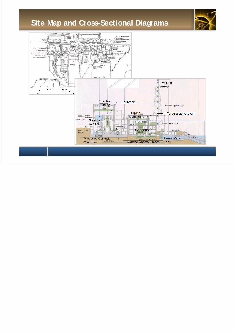
Site Map and Cross-Sectional Diagrams