ansi isa tr12.13.01 r2005_flammability characteristics of combustible gases and vapors
DESCRIPTION
AnsiTRANSCRIPT

Flammability Characteristics ofCombustible Gases and Vapors
Reaffirmed 31 August 2005
ANSI/ISA–TR12.13.01–1999 (R2005)
T E C H N I C A L R E P O R T
ISA The Instrumentation,Systems, and
Automation Society
–TM
A Technical Report prepared by ISA and registered with ANSI
Copyright The Instrumentation, Systems, and Automation Society Provided by IHS under license with ISA
Not for ResaleNo reproduction or networking permitted without license from IHS
--`,,```,,,,````-`-`,,`,,`,`,,`---

Copyright The InstrumProvided by IHS underNo reproduction or net
--`,,```,,,,```
Copyright ��2005 by ISA. All rights reserved. Printed in the United States of America. No part of this publication may be reproduced, stored in a retrieval system, or transmitted, in any form or by any means (electronic, mechanical, photocopying, recording, or otherwise), without the prior written permission of the Publisher.
ISA67 Alexander DriveP.O. Box 12277Research Triangle Park, North Carolina 27709
ANSI/ISA–TR12.13.01–1999 (R2005)Flammability Characteristics of Combustible Gases and Vapors
ISBN: 1-55617-697-X
entation, Systems, and Automation Society license with ISA
Not for Resaleworking permitted without license from IHS
`-`-`,,`,,`,`,,`---
— 3 — ANSI/ISA-TR12.13.01-1999 (R2005)
Copyright The InstrumProvided by IHS underNo reproduction or net
--`,,```,,,,```
PREFACE
This preface, as well as all footnotes and annexes, is included for information purposes and is not part ofANSI/ISA-TR12.13.01-1999 (R2005).
This Standard has been prepared as part of the service of ISA toward a goal of uniformity in the field of instrumentation. To be of real value, this document should not be static but should be subject to periodic review. Toward this end, the Society welcomes all comments and criticisms and asks that they be addressed to the Secretary, Standards and Practices Board; ISA; 67 Alexander Drive; P. O. Box 12277; Research Triangle Park, NC 27709; Telephone (919) 549-8411; Fax (919) 549-8288; E-mail: [email protected].
The ISA Standards and Practices Department is aware of the growing need for attention to the metric system of units in general, and the International System of Units (SI) in particular, in the preparation of instrumentation standards. The Department is further aware of the benefits to USA users of ISA standards of incorporating suitable references to the SI (and the metric system) in their business and professional dealings with other countries. Toward this end, this Department will endeavor to introduce SI-acceptable metric units in all new and revised standards, recommended practices, and technical reports to the greatest extent possible. Standard for Use of the International System of Units (SI): The Modern Metric System, published by the American Society for Testing & Materials as IEEE/ASTM SI 10-97, and future revisions, will be the reference guide for definitions, symbols, abbreviations, and conversion factors.
It is the policy of ISA to encourage and welcome the participation of all concerned individuals and interests in the development of ISA standards, recommended practices, and technical reports. Participation in the ISA standards-making process by an individual in no way constitutes endorsement by the employer of that individual, of ISA, or of any of the standards, recommended practices, and technical reports that ISA develops.
CAUTION—ISA ADHERES TO THE POLICY OF THE AMERICAN NATIONAL STANDARDS INSTITUTE WITH REGARD TO PATENTS. IF ISA IS INFORMED OF AN EXISTING PATENT THAT IS REQUIRED FOR USE OF THE STANDARD, IT WILL REQUIRE THE OWNER OF THE PATENT TO EITHER GRANT A ROYALTY-FREE LICENSE FOR USE OF THE PATENT BY USERS COMPLYING WITH THE STANDARD OR A LICENSE ON REASONABLE TERMS AND CONDITIONS THAT ARE FREE FROM UNFAIR DISCRIMINATION.
EVEN IF ISA IS UNAWARE OF ANY PATENT COVERING THIS STANDARD, THE USER IS CAUTIONED THAT IMPLEMENTATION OF THE STANDARD MAY REQUIRE USE OF TECHNIQUES, PROCESSES, OR MATERIALS COVERED BY PATENT RIGHTS. ISA TAKES NO POSITION ON THE EXISTENCE OR VALIDITY OF ANY PATENT RIGHTS THAT MAY BE INVOLVED IN IMPLEMENTING THE STANDARD. ISA IS NOT RESPONSIBLE FOR IDENTIFYING ALL PATENTS THAT MAY REQUIRE A LICENSE BEFORE IMPLEMENTATION OF THE STANDARD OR FOR INVESTIGATING THE VALIDITY OR SCOPE OF ANY PATENTS BROUGHT TO ITS ATTENTION. THE USER SHOULD CAREFULLY INVESTIGATE RELEVANT PATENTS BEFORE USING THE STANDARD FOR THE USER’S INTENDED APPLICATION.
HOWEVER, ISA ASKS THAT ANYONE REVIEWING THIS STANDARD WHO IS AWARE OF ANY PATENTS THAT MAY IMPACT IMPLEMENTATION OF THE STANDARD NOTIFY THE ISA STANDARDS AND PRACTICES DEPARTMENT OF THE PATENT AND ITS OWNER.
entation, Systems, and Automation Society license with ISA
Not for Resaleworking permitted without license from IHS
`-`-`,,`,,`,`,,`---

ANSI/ISA-TR12.13.01-1999 (R2005) — 4 —
1-1999:
Copyright The InstrumProvided by IHS underNo reproduction or net
ADDITIONALLY, THE USE OF THIS STANDARD MAY INVOLVE HAZARDOUS MATERIALS, OPERATIONS OR EQUIPMENT. THE STANDARD CANNOT ANTICIPATE ALL POSSIBLE APPLICATIONS OR ADDRESS ALL POSSIBLE SAFETY ISSUES ASSOCIATED WITH USE IN HAZARDOUS CONDITIONS. THE USER OF THIS STANDARD MUST EXERCISE SOUND PROFESSIONAL JUDGMENT CONCERNING ITS USE AND APPLICABILITY UNDER THE USER’S PARTICULAR CIRCUMSTANCES. THE USER MUST ALSO CONSIDER THE APPLICABILITY OF ANY GOVERNMENTAL REGULATORY LIMITATIONS AND ESTABLISHED SAFETY AND HEALTH PRACTICES BEFORE IMPLEMENTING THIS STANDARD.
The following people served as members of ISA Subcommittee SP12.13 and approved ANSI/ISA-TR12.13.0
NAME COMPANY
M. Coppler, Chairman* Ametek Inc.D. Bishop, Managing Director Chevron Petroleum Technology CompanyW. Alexander Mine Safety Appliances CompanyD. Ankele* Underwriters Laboratories Inc.B. Apel MSA InstrumentR. Bierzynski Scott Health & SafetyE. Briesch* Underwriters Laboratories Inc.C. Brown Enmet CorporationS. Bruce Delphian CorporationJ. Cawley U.S. Dept of the InteriorJ. Chilton U.S. Bureau of MinesD. Chou International Sensor Tech.C. Coache* Factory Mutual Research CorporationS. Czaniecki Intrinsic Safety Concepts Inc.L. Greenwalt Marathon Oil Co.C. Groppetti* Detector Electronics Corp.A. Guerrera Sola Communications Inc.L. Hamman U.S. Coast GuardK. Hedrick U.S. Dept. of LaborC. Hendrickson Northern Illinois Gas Co.B. Holcom Gas Tech. Inc.K. Johnson KWJ Engineering Inc.P. Kelly* Underwriters Laboratories, Inc.R. Landman Intl. Marine Products Inc.D. Li Canadian Standards Assoc.R. Lyle Motorola Inc.J. McCann International Sensor TechnologiesR. Menot* Factory Mutual Research Corp.J. Miller* Detector Electronics Corp.R. Merritt Edu-tech IndustriesR. Novack* Ametek Inc.K. Patel Scott AviationR. Poling EI du PontD. Pongrance General MonitorsM. Schaeffer Control Instruments CorporationW. Shao Canadian Standards Association
______* One vote per company.
--`,,```,,,,````-`-`,,`,,`,`,,`---
entation, Systems, and Automation Society license with ISA
Not for Resaleworking permitted without license from IHS

— 5 — ANSI/ISA-TR12.13.01-1999 (R2005)
:
Copyright The InstrumProvided by IHS underNo reproduction or net
D. Styrcula Underwriters Laboratories Inc.J. Thomason OMNI Industrial Systems, Inc.D. Wagner Industrial Scientific Corp.R. Wanek Bacharach Inc.D. Wechsler Union Carbide CorporationR. Wek General MonitorsD. Wolsk Wolsk Alarms, Ltd.
The following people served as members of ISA Committee SP12 and approved ANSI/ISA-TR12.13.01-1999
NAME COMPANY
F. McGowan, Chairman* Factory Mutual Research CorporationD. Bishop, Managing Director* Chevron Petroleum Technology CompanyN. Abbatiello* Eastman Kodak CompanyD. Ankele* Underwriters Laboratories Inc.B. Apel MSA InstrumentA. Ballard* Crouse-Hinds CompanyG. Bentinck E. I. du PontK. Boegli Phoenix Contact Inc.R. Brodin Fisher Controls International, Inc.M. Buettner Ralston Purina CompanyR. Buschart PC & E, Inc.R. Cardinal Bently Nevada CorporationC. Casso Schlumberger Oil Field ServicesM. Coppler Ametek Inc.J. Cospolich Waldemar S. Nelson & Company, Inc.J. Costello Henkel Corp.S. Czaniecki Intrinsic Safety Concepts Inc.T. Dubaniewicz NIOSHU. Dugar Mobil Chemical CompanyA. Engler EGS Electrical GroupT. Feindel R. Stahl, Inc.W. Fiske Intertek Testing ServicesG. Garcha PCS EngineeringE. Geissler Bartec US Corp.E. Henning Bailey-Fischer & PorterD. Hohenstein Pepperl+Fuchs Inc.D. Jagger* Hawke AmericaJ. Kuczka KillarkB. Larson Turck Inc.W. Lawrence* Factory Mutual Research Corp.E. Magison Honeywell, Inc.R. Masek Bailey Controls CompanyK. McManama* Underwriters Laboratories Inc.I. McMurchie Petromarine of TexasR. McNeal* Hawke AmericaA. Mobley* 3M CompanyS. Nguyen Milltronics Ltd.
______* One vote per company.
entation, Systems, and Automation Society license with ISA
Not for Resaleworking permitted without license from IHS
--`,,```,,,,````-`-`,,`,,`,`,,`---
ANSI/ISA-TR12.13.01-1999 (R2005) — 6 —
Copyright The InstrumProvided by IHS underNo reproduction or net
E. Olson* 3M CompanyA. Page III MSHA Certification CenterJ. Propst Shell Oil Products Co.T. Schnaare Rosemount, Inc.W. Shao Canadian Standards Assoc.J. Thomason OMNI Industrial Systems, Inc.D. Wechsler Union Carbide Corporation
The following members of the ISA Standards and Practices Board approved ANSI/ISA-TR12.13.01-1999 for publication on 28 February 1999.
NAME COMPANY
H. Dammeyer The Ohio State UniversityH. Baumann H. D. Baumann, Inc.D. Bishop Chevron Petroleum Technology CompanyP. Brett Honeywell, Inc.M. Cohen Senior Flexonics, Inc.M. Coppler Ametek, Inc.W. Holland Southern CompanyA. Iverson Ivy OptiksR. Jones Dow Chemical Co.V. Maggioli Feltronics Corp.T. McAvinew Instrumentation & Control Engineering LLCA. McCauley, Jr. Chagrin Valley Controls, Inc.R. McFarland Honeywell, Inc.R. Reimer Rockwell AutomationJ. Rennie Factory Mutual Research Corp.R. Webb Altran Corp.W. Weidman Parsons Energy & Chemicals GroupJ. Weiss EPRIJ. Whetstone National Institute of Standards & TechnologyM. Widmeyer ConsultantR. Wiegle CANUS Corp.C. Williams Eastman Kodak Co.G. Wood Graeme Wood ConsultingM. Zielinski Fisher-Rosemount Systems, Inc.
______* One vote per company.
entation, Systems, and Automation Society license with ISA
Not for Resaleworking permitted without license from IHS
--`,,```,,,,````-`-`,,`,,`,`,,`---

⎯ 7 ⎯ ANSI/ISA-TR12.13-01-1999 (R2005)
The following people served as members of ISA Subcommittee SP12.13 and reaffirmed ANSI/ISA-TR12.13.01-1999 (R2005):
NAME COMPANY
J. Miller, Chairman Detector Electronics Corporation M. Coppler, Managing Director Ametek Inc. J. Berthold Senscient Ltd. R. Bolotin General Monitors Inc. C. Brown Enmet Corporation S. Bruce Delphian Corporation P. Byrne FM Approvals S. Czaniecki Intrinsic Safety Concepts Inc. G. Garcha GE Energy K. Hedrick MSHA Approval & Certification Center B. Holcom RKI Instruments D. Mills Underwriters Laboratories Inc. L. Owen Dooley Tackaberry Inc. M. Phadke Bayer India Ltd. R. Poling E I du Pont M. Schaeffer Control Instruments Corporation P. Schimmoeller CSA International R. Seitz Artech Engineering A. Skinner Crowcon Gas Detection K. Thompson MSA Company D. Wechsler Dow Chemical Company C. Yong Shell Exploration & Production Company The following people served as members of ISA Committee SP12 and reaffirmed ANSI/ISA-TR12.13.01-1999 (R2005):
NAME COMPANY
T. Schnaare, Chairman Rosemount, Inc. W. Lawrence, Co-Chairman FM Approvals M. Coppler, Managing Director Ametek Inc. N. Abbatiello Optimation Technology D. Ankele Underwriters Laboratories Inc. A. Ballard Crouse Hinds Division of Cooper Industries D. Bishop David N Bishop Consultant H. Bockle R. Stahl Inc. K. Boegli Phoenix Contact Inc. D. Burns Shell Exploration & Production Company R. Buschart Cable Tray Institute R. Cardinal Bently Nevada LLC C. Casso Nabors Industries J. Cospolich Waldemar S Nelson & Company Inc. S. Czaniecki Intrinsic Safety Concepts Inc. J. Dolphin Professional Testing T. Dubaniewicz NIOSH U. Dugar Mobil Chemical Company A. Engler EGS/ECM W. Fiske Intertek Testing Services G. Garcha GE Energy D. Hohenstein Pepperl + Fuchs Inc. D. Jagger Bifold-Fluid Power
Copyright The Instrumentation, Systems, and Automation Society Provided by IHS under license with ISA
Not for ResaleNo reproduction or networking permitted without license from IHS
--`,,```,,,,````-`-`,,`,,`,`,,`---

ANSI/ISA-TR12.13-01-1999 (R2005) ⎯ 8 ⎯
J. Jonscher Adalet PLM F. Kent Honeywell Inc. P. Kovscek Industrial Scientific Corporation J. Kuczka Killark B. Larson Turck Inc. E. Massey Rockwell Automation A. Mobley 3M Company A. Page MSHA Approval & Certification Center P. Schimmoeller CSA International R. Seitz Artech Engineering D. Wechsler Dow Chemical Company ANSI/ISA-TR12.13.01-1999 (R2005) was reaffirmed by the following ISA Standards and Practices Board on 26 August 2005.
NAME COMPANY
I. Verhappen, Chair Syncrude Canada Ltd. F. Amir E I Du Pont Company D. Bishop David N Bishop, Consultant M. Coppler Ametek, Inc. B. Dumortier Schneider Electric W. Holland Consultant E. Icayan ACES Inc A. Iverson Ivy Optiks R. Jones Consultant V. Maggioli Feltronics Corporation T. McAvinew Jacobs Engineering Group A. McCauley Chagrin Valley Controls, Inc. G. McFarland Emerson Process Management Power & Water Sol. R. Reimer Rockwell Automation J. Rennie Consultant N. Sands E I du Pont H. Sasajima Yamatake Corporation T. Schnaare Rosemount Inc. A. Summers SIS-TECH Solutions LLC R. Webb Consultant W. Weidman Worley Parsons J. Weiss KEMA Inc. M. Widmeyer Stanford Linear Accelerator Center C. Williams Eastman Kodak Company M. Zielinski Emerson Process Management
Copyright The Instrumentation, Systems, and Automation Society Provided by IHS under license with ISA
Not for ResaleNo reproduction or networking permitted without license from IHS
--`,,```,,,,````-`-`,,`,,`,`,,`---
— 9 — ANSI/ISA-TR12.13.01-1999 (R2005)
CONTENTS
Copyright The InstrumProvided by IHS underNo reproduction or net
--`,,```,,,,````-`-`,,`,,`,`,,`---
FOREWORD .........................................................................................................................................11
ABSTRACT ...........................................................................................................................................11
KEY WORDS.........................................................................................................................................11
APPENDIX I ........................................................................................................................................ 13
entation, Systems, and Automation Society license with ISA
Not for Resaleworking permitted without license from IHS

Copyright The InstrumProvided by IHS underNo reproduction or net
--`,,```,,,,````-`-`,,`,,`,`,,`---
This page intentionally left blank.entation, Systems, and Automation Society license with ISA
Not for Resaleworking permitted without license from IHS

— 11 — ANSI/ISA-TR12.13.01-1999 (R2005)
FOREWORD
Publication of this Technical Report that has been registered with ANSI has been approved by the Accredited Standards Developer ISA, 67 Alexander Drive, Research Triangle Park, NC 27709. This document is registered as a Technical Report according to the Procedures for the Registration of Technical Reports with ANSI. This document is not an American National Standard and the material contained herein is not normative in nature. Comments on the content of this document should be sent to the Secretary, Standards and Practices Board; ISA; 67 Alexander Drive; P. O. Box 12277; Research Triangle Park, NC 27709.
As a service to industry, the accompanying document, Bureau of Mines Bulletin 627 - Flammability Characteristics of Combustible Gases and Vapors, by Zabetakis 1965, is hereby reprinted in its entirety.
This compendium, formerly available from the U.S. Bureau of Mines, contains information essential to an understanding of detection, measurement and handling of flammable gases and vapors.
For further information, refer to ANSI/ISA–TR12.13.02.
The reader should be aware that more recent LFL/UFL figures are available in NFPA 497, and IEC 60079-20.
ABSTRACT
This technical report includes theoretical and practical work carried out and collected by the U.S. Bureau of Mines relating to ignition and explosive properties of flammable gas mixtures. Flammability limits, under varying conditions of proportion, temperature and pressure, are presented.
While the primary emphasis is on methane-air mixtures as found in coal mines, a full treatment of many other gases and vapors is included.
KEY WORDS
Methane
Fire
Explosion
Flammability limits
Flammable
Combustible
LEL, UEL
LFL, UFL
Gas
Copyright The Instrumentation, Systems, and Automation Society Provided by IHS under license with ISA
Not for ResaleNo reproduction or networking permitted without license from IHS
--`,,```,,,,````-`-`,,`,,`,`,,`---

This page intentionally left blank.
Copyright The Instrumentation, Systems, and Automation Society Provided by IHS under license with ISA
Not for ResaleNo reproduction or networking permitted without license from IHS
--`,,```,,,,````-`-`,,`,,`,`,,`---

— 13 — ANSI/ISA-TR12.13.01-1999 (R2005)
Copyright The InstrumProvided by IHS underNo reproduction or net
--`,,```,,,,````-`-`,,`,,`,`,,`---
APPENDIX I
The following document, Flammability Characteristics of Combustible Gases and Vapors, is reprinted in its entirety by permission of the publisher, the Bureau of Mines, U.S. Department of the Interior.
entation, Systems, and Automation Society license with ISA
Not for Resaleworking permitted without license from IHS

ANSI/ISA-TR12.13.01-1999 (R2005) — 14 —
Copyright The InstrumProvided by IHS underNo reproduction or net
--`,,```,,,,````-`-`,,`,,`,`,,`---
Bulletin 627
Bureau of Mines
AD 701 576
FLAMMABILITY CHARACTERISTICS OF COMBUSTIBLE GASES AND VAPORS,U.S. Bureau of Mines, Bulletin 627
By Michael G. Zabetakis
entation, Systems, and Automation Society license with ISA
Not for Resaleworking permitted without license from IHS

— 15 — ANSI/ISA-TR12.13.01-1999 (R2005)
Copyright The InstrumProvided by IHS underNo reproduction or net
--`,,```,,,,````-`-`,,`,,`,`,,`---
This publication has been cataloged as follows:
Zabetakis, Michael George, 1924-2005
Flammability characteristics of combustible gases and vapors. [Washington] U.S. Dept. of the Interior, Bureau of Mines [1965]
121 p. illus., tables. (U.S. Bureau of Mines. Bulletin 627)
Includes bibliography.
1. Combustion gases. 2. Gases. 3. Vapors. I. Title. II. Title: Combustible gases. (Series)
TN23.U4 no. 627 622.06173
U.S. Dept. of the Int. LibraryA.1—
entation, Systems, and Automation Society license with ISA
Not for Resaleworking permitted without license from IHS

ANSI/ISA-TR12.13.01-1999 (R2005) — 16 —
Copyright The InstrumProvided by IHS underNo reproduction or net
FLAMMABILITY CHARACTERISTICS OF COMBUSTIBLE GASES AND VAPORS
by
Michael G. Zabetakis"
Abstract
This is a summary of the available limit of flammability, autoignition, and burning-rate data for more than 200 combustible gases and vapors in air and other oxidants, as well as of empirical rules and graphs that can be used to predict similar data for thousands of other combustibles under a variety of environmental conditions. Specific data are presented on the paraffinic, unsaturated, aromatic, and alicyclic hydrocarbons, alcohols, ethers, aldehydes, ketones, and sulfur compounds, and an assortment of fuels, fuel blends, hydraulic fluids, engine oils, and miscellaneous combustible gases and vapors.
Introduction
Prevention of unwanted fires and gas explosion disasters requires a knowledge of flammability characteristics (limits of flammability, ignition requirements, and burning rates) of pertinent combustible gases and vapors likely to be encountered under various conditions of use (or misuse). Available data may not always be adequate for use in a particular application since they may have been obtained at a lower temperature and pressure than is encountered in practice. For example, the quantity of air that is required to decrease the combustible vapor concentration to a safe level in a particular process carried out at 200°C should be based on flammability data obtained at this temperature. When these are not available, suitable approximations can be made to permit a realistic evaluation of the hazards associated with the process being considered; such approximations can serve as the basis for designing suitable safety devices for the protection of personnel and equipment.
The purpose of this bulletin is to present a general review of the subject of flammability, and to supply select experimental data and empirical rules on the flammability characteristics of various families of combustible gases and vapors in air and other oxidizing atmospheres. It contains what are believed to be the latest and most reliable data for more than 200 combustibles of interest to those concerned with the prevention of disastrous gas explosions. In addition, the empirical rules and graphs presented here can be used to predict similar data for other combustibles under a variety of conditions. This bulletin supplements Bureau bulletins (40)N and other publications (158).
"Physical chemist, project coordinator, Gas Explosion, Explosives Research Center, Bureau of Mines, Pittsburgh, Pa.Work on manuscript completed May 1964.NItalicized numbers in parentheses refer to items in the bibliography at the end of this report.
entation, Systems, and Automation Society license with ISA
Not for Resaleworking permitted without license from IHS
--`,,```,,,,````-`-`,,`,,`,`,,`---
— 17 — ANSI/ISA-TR12.13.01-1999 (R2005)
Copyright The InstrumProvided by IHS underNo reproduction or net
--`,,```,,,,````-`-`,,`,,`,`,,`---
Basic knowledge of combustion is desirable for a thorough understanding of the material, which can be found in numerous publications (69, 199, 202). Therefore, only those aspects required for an understanding of flammability are considered here; even these are considered from a fairly elementary viewpoint.
Definitions and Theory
LIMITS OF FLAMMABILITY
A combustible gas-air mixture can be burned over a wide range of concentrations—when either subjected to elevated temperatures or exposed to a catalytic surface at ordinary temperatures. However, homogeneous combustible gas-air mixtures are flammable, that is, they can propagate flame freely within a limited range of compositions. For example, trace amounts of methane in air can be readily oxidized on a heated surface, but a flame will propagate from an ignition source at ambient temperatures and pressures only if the surrounding mixture contains at least 5 but less than 15 volume-percent methane. The more dilute mixture is known as the lower limit, or combustible-lean limit, mixture; the more concentrated mixture is known as the upper limit, or combustible-rich limit, mixture. In practice, the limits of flammability of a particular system of gases are affected by the temperature, pressure, direction of flame propagation, gravitational field strength, and surroundings. The limits are obtained experimentally by determining the limiting mixture compositions between flammable and non-flammable mixtures (244). That is,
(1)
and
(2)
where LT,P and UT,P are the lower and upper limits of flammability, respectively, at a specified temperature and pressure, Cgn and C1n are the greatest and least concentrations of fuel in oxidant that are nonflammable, and C1f and Cgf are the least and greatest concentrations of fuel in oxidant that are flammable. The rate at which a flame propagates through a flammable mixture depends on a number of factors including temperature, pressure, and mixture composition. It is a minimum at the limits of flammability and a maximum at near stoichiometric mixtures (130).
The Bureau of Mines has adopted a standard apparatus for limit-of-flammability determinations (40). Originally designed for use at atmospheric pressure and room temperature, it was later modified for use at reduced pressures by incorporating a spark-gap ignitor in the base of the 2-inch, glass, flame-propagation tube. This modification introduced a difficulty that was not immediately apparent, as the spark energy was not always adequate for use in limit-of-flammability determinations. Figure 1 illustrates the effect of mixture composition on the electrical spark energy requirements for ignition of methane-air mixtures (75). For example, a 0.2-millijoule (mj) spark is inadequate to ignite even a stoichiometric mixture at atmospheric pressure and 26°C; a 1-mj spark can ignite mixtures containing between 6 and 11.5 volume-percent methane, etc. Such limit-mixture compositions that depend on the ignition source strength may be defined as limits of ignitibility or more simply ignitibility limits; they are thus
LT P� 1/2 Cgn C1f+� �,=
UT P� 1/2 Cgf C1n+� �,=
entation, Systems, and Automation Society license with ISA
Not for Resaleworking permitted without license from IHS

ANSI/ISA-TR12.13.01-1999 (R2005) — 18 —
Copyright The InstrumProvided by IHS underNo reproduction or net
--`,,```,,,,````-`-`,,`,,`,`,,`---
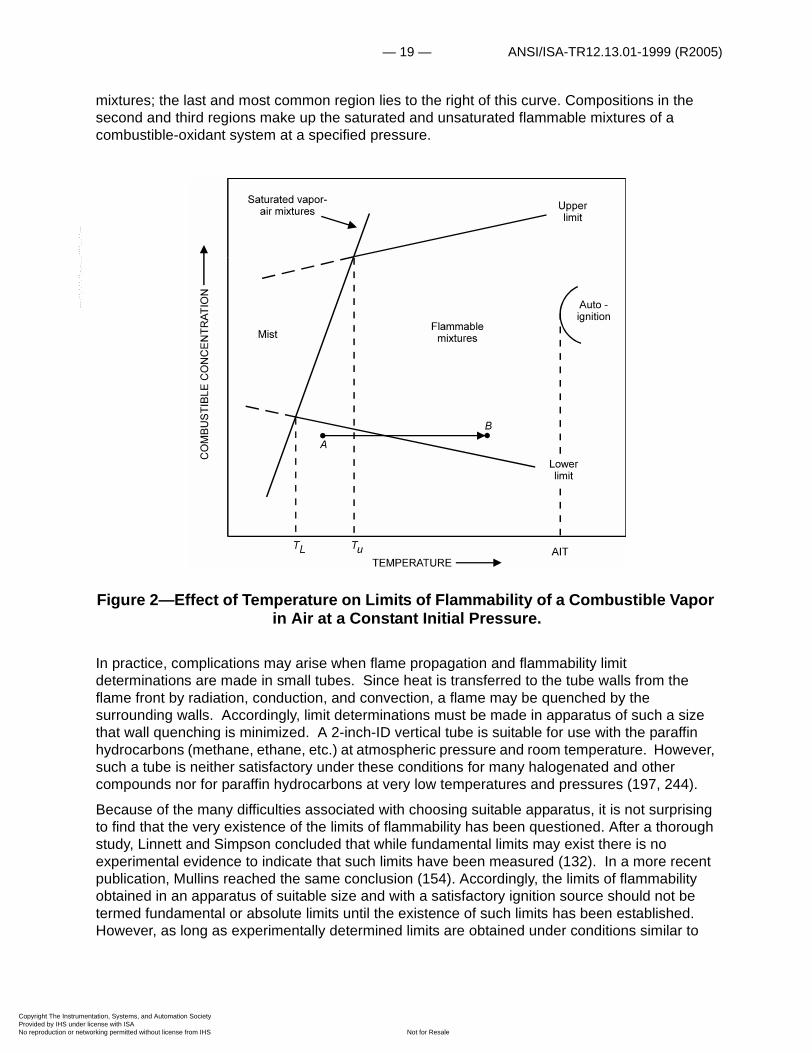
indicative of the igniting ability of the energy source. Limit mixtures that are essentially independent of the ignition source strength and that give a measure of the ability of a flame to propagate away from the ignition source may be defined as limits of flammability. Considerably greater spark energies are required to establish limits of flammability than are required for limits of ignitibility (218); further, more energy is usually required to establish the upper limit than is required to establish the lower limit. In general, when the source strength is adequate, mixtures just outside the range of flammable compositions yield flame caps when ignited. These flame caps propagate only a short distance from the ignition source in a uniform mixture. The reason for this may be seen in figure 2 which shows the effect of temperature on limits of flammability at a constant initial pressure. As the temperature is increased, the lower limit decreases and the upper limit increases. Thus, since a localized energy source elevates the temperature of nearby gases, even a nonflammable mixture can propagate flame a short distance from the source. That is, a nonflammable mixture (for example, composition-temperature point A, fig. 2) may become flammable for a time, if its temperature is elevated sufficiently (composition-temperature point B).
Figure 1—Ignitibility Curve and Limits of Flammability for Methane-Air Mixtures at Atmospheric Pressure and 26°C.
Flammable mixtures considered in figure 2 fall in one of three regions. The first is left of the saturated vapor-air mixtures curve, in the region labeled "Mist". Such mixtures consist of droplets suspended in a vapor-air mixture; they are discussed in greater detail in the section on formation of flammable mixtures. The second lies along the curve for saturated vapor-air
entation, Systems, and Automation Society license with ISA
Not for Resaleworking permitted without license from IHS
— 19 — ANSI/ISA-TR12.13.01-1999 (R2005)
Copyright The InstrumProvided by IHS underNo reproduction or net
--`,,```,,,,````-`-`,,`,,`,`,,`---
mixtures; the last and most common region lies to the right of this curve. Compositions in the second and third regions make up the saturated and unsaturated flammable mixtures of a combustible-oxidant system at a specified pressure.
Figure 2—Effect of Temperature on Limits of Flammability of a Combustible Vapor in Air at a Constant Initial Pressure.
In practice, complications may arise when flame propagation and flammability limit determinations are made in small tubes. Since heat is transferred to the tube walls from the flame front by radiation, conduction, and convection, a flame may be quenched by the surrounding walls. Accordingly, limit determinations must be made in apparatus of such a size that wall quenching is minimized. A 2-inch-ID vertical tube is suitable for use with the paraffin hydrocarbons (methane, ethane, etc.) at atmospheric pressure and room temperature. However, such a tube is neither satisfactory under these conditions for many halogenated and other compounds nor for paraffin hydrocarbons at very low temperatures and pressures (197, 244).
Because of the many difficulties associated with choosing suitable apparatus, it is not surprising to find that the very existence of the limits of flammability has been questioned. After a thorough study, Linnett and Simpson concluded that while fundamental limits may exist there is no experimental evidence to indicate that such limits have been measured (132). In a more recent publication, Mullins reached the same conclusion (154). Accordingly, the limits of flammability obtained in an apparatus of suitable size and with a satisfactory ignition source should not be termed fundamental or absolute limits until the existence of such limits has been established. However, as long as experimentally determined limits are obtained under conditions similar to
entation, Systems, and Automation Society license with ISA
Not for Resaleworking permitted without license from IHS
ANSI/ISA-TR12.13.01-1999 (R2005) — 20 —
Copyright The InstrumProvided by IHS underNo reproduction or net
--`,,```,,,,````-`-`,,`,,`,`,,`---
those found in practice, they may be used to design installations that are safe and to assess potential gas-explosion hazards.
Industrially, heterogeneous single-phase (gas) and multi-phase (gas, liquid, and solid) flammable mixtures are probably even more important than homogeneous gas mixtures. Unfortunately, our knowledge of such mixtures is rather limited. It is important to recognize, however, that heterogeneous mixtures can ignite at concentrations that would normally be nonflammable if the mixture were homogeneous. For example, 1 liter of methane can form a flammable mixture with air near the top of a 100-liter container, although a nonflammable (1.0 volume-percent) mixture would result if complete mixing occurred at room temperature. This is an important concept, since layering can occur with any combustible gas or vapor in both stationary and flowing mixtures. Roberts, Pursall, and Sellers (176-180) have presented an excellent series of review articles on the layering and dispersion of methane in coal mines.
The subject of flammable sprays, mists, and foams is well-documented (5, 18, 22, 27, 76, 205, 215, 245). Again, where such heterogeneous mixtures exist, flame propagation can occur at so-called average concentrations well below the lower limit of flammability (86); thus, the term "average" may be meaningless when used to define mixture composition in heterogeneous systems.
IGNITION
Lewis and von Elbe (130), Mullins (153,154), and Belles and Swett (156) have prepared excellent reviews of the processes associated with spark-ignition and spontaneous-ignition of a flammable mixture. In general, many flammable mixtures can be ignited by sparks having a relatively small energy content (1 to 100 mj) but a large power density (greater than 1 megawatt/cm3). However, when the source energy is diffuse, as in a sheet discharge, even the total energy requirements for ignition may be extremely large (79, 82, 85, 123, 181, 228). There is still much to be learned in this field, however, since electrical discharges are not normally as well defined in practice as they are in the laboratory.
When a flammable mixture is heated to an elevated temperature, a reaction is initiated that may proceed with sufficient rapidity to ignite the mixture. The time that elapses between the instant the mixture temperature is raised and that in which a flame appears is loosely called the time lag or time delay before ignition. In general, this time delay decreases as the temperature increases. According to Semenov (193), these quantities are related by the expression
(3)
where ��is the time delay before ignition in seconds; E is an apparent activation energy for the rate controlling reaction in calories per mole; T is the absolute temperature, expressed in degrees, Kelvin; and B is a constant. Two types of ignition temperature data are found in the current literature. In the first, the effect of temperature on time delay is considered for delays of less than 1 second (127, 153). Such data are applicable to systems in which the contact time between the heated surface and a flowing flammable mixture is very short; they are not satisfactory when the contact time is indefinite. Further, equation (3) is of little help, because it gives only the time delay for a range of temperatures at which autoignition occurs; if the temperature is reduced sufficiently, ignition does not occur. From the standpoint of safety, it is the lowest temperature at which ignition can occur that is of interest. This is called the minimum
�log 0.22ET
-------------- B�+=
entation, Systems, and Automation Society license with ISA
Not for Resaleworking permitted without license from IHS
— 21 — ANSI/ISA-TR12.13.01-1999 (R2005)
Copyright The InstrumProvided by IHS underNo reproduction or net
--`,,```,,,,````-`-`,,`,,`,`,,`---
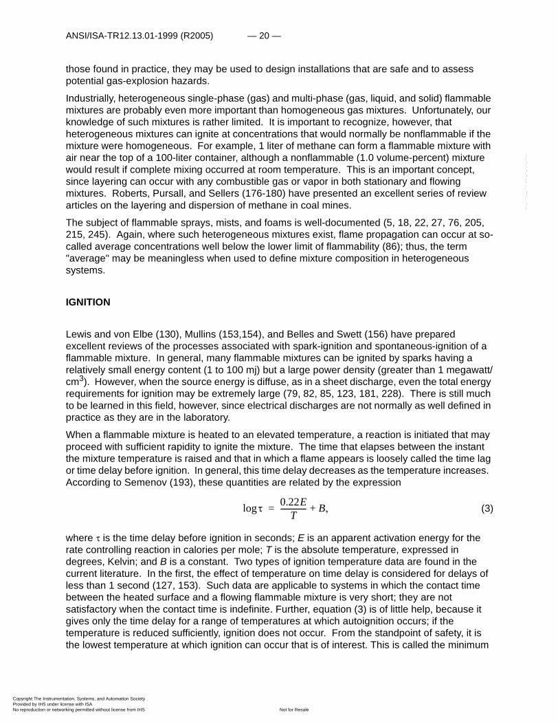
spontaneous-ignition, or autoignition, temperature (AIT) and is determined in a uniformly heated apparatus that is sufficiently large to minimize wall quenching effects (194, 237). Figures 3 and 4 illustrate typical autoignition-temperature data. In figure 3 the minimum autoignition-temperature or AIT value for n-propyl nitrate is 170° C at an initial pressure of 1,000 psig (243). Data in this figure may be used to construct a log ��versus plot such as that in figure 4. Such graphs illustrate the applicability of equation (3) to autoignition temperature data. The equation of the broken line in figure 4 is
. (4)
In this specific case, equation (4) is applicable only in the temperature range from 170° to 195°C; another equation must be used for data at higher temperatures. The solid lines in figure 4 define an 8°C band that includes the experimental points in the temperature range from 170° to 195°C.
FORMATION OF FLAMMABLE MIXTURES
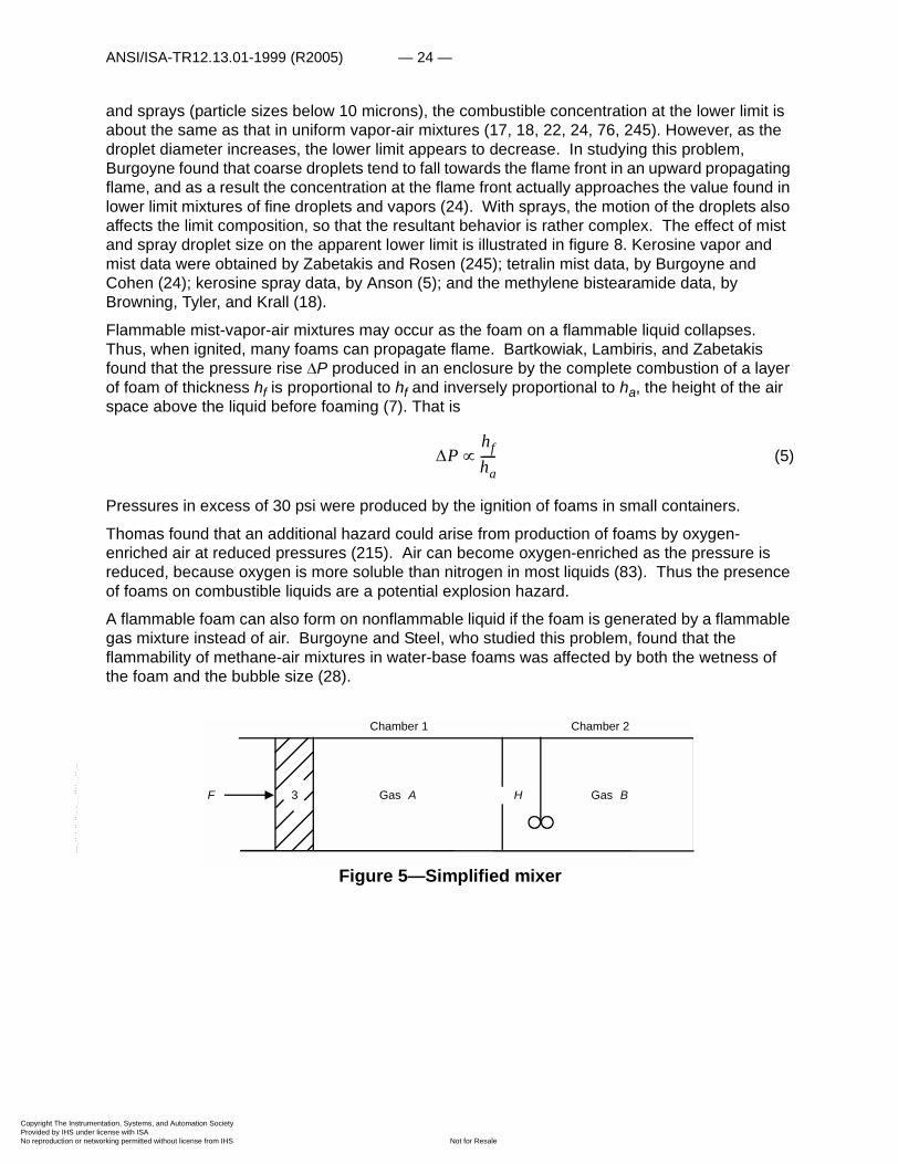
In practice, heterogeneous mixtures are always formed when two gases or vapors are first brought together. Before discussing the formation of such mixtures in detail, a simplified mixer such as that shown in figure 5 will be considered briefly. This mixer consists of chambers 1 and 2 containing gases A and B, respectively; chamber 2, which contains a stirrer, is separated from chamber 1 and piston 3 by a partition with a small hole, H. At time to, a force F applied to piston 3 drives gas A into chamber 2 at a constant rate. If gas A is distributed instantaneously throughout chamber 2 as soon as it passes through H, a composition diagram such as that given in figure 6 results; the (uniform) piston motion starts at to, and stops at tF. However, if a time interval �t is required to distribute a small volume from chamber 1 throughout chamber 2, then at any instant between to, and tF + �t, a variety of mixture compositions exists in chamber 2. This situation is represented schematically in figure 7. The interval of time during which heterogeneous gas mixtures would exist in the second case is determined in part by the rate at which gas A is added to chamber 2, by the size of the two chambers, and by the efficiency of the stirrer.
In practice, flammable mixtures may form either by accident or design. When they are formed by accident, it is usually desirable to reduce the combustible concentration quickly by adding enough air or inert gas to produce nonflammable mixtures. Under certain conditions, it may be possible to increase the combustible concentration so as to produce a nonflammable mixture. Such procedures are discussed in greater detail in the following section.
Flammable mixtures are encountered in production of many chemicals and in certain physical operations. These include gasfreeing a tank containing a combustible gas (232), drying plastic-wire coating, and recovering solvent from a solvent-air mixture. When layering can occur, as in drying operations, it is not enough to add air at such a rate that the overall mixture composition is below the lower limit of flammability (assuming that uniform mixtures result). Special precautions must be taken to assure the rapid formation of nonflammable mixtures (235). When a batch process is involved, an added precaution must be taken; a constituent at a partial pressure near its vapor pressure value may condense when it is momentarily compressed by addition of other gases or vapors. Accordingly, mixtures that are initially above the upper limit of flammability may become flammable. A similar effect, must be considered when mixtures are sampled with equipment that is cooler than the original sample; if vapor condenses in the sampling line, the
1T---
�log 12.3 103�T
------------------------- 25.1–=
entation, Systems, and Automation Society license with ISA
Not for Resaleworking permitted without license from IHS
ANSI/ISA-TR12.13.01-1999 (R2005) — 22 —
Copyright The InstrumProvided by IHS underNo reproduction or net
test sample will not yield accurate data. A flammable mixture sampled in this manner may appear to be nonflammable and thus create a hazardous situation (236).
entation, Systems, and Automation Society license with ISA
Not for Resaleworking permitted without license from IHS
--`,,```,,,,````-`-`,,`,,`,`,,`---

— 23 — ANSI/ISA-TR12.13.01-1999 (R2005)
Copyright The InstrumProvided by IHS underNo reproduction or net
Figure 3—Time Delay Before Ignition of NPN in Air at 1,000 Psig in the Temperature Range From 150° to 210°C. (1-33 apparatus; type-347,
stainless steel test chamber.)
TEMPERATURE, �C
Figure 4—Logarithm of Time Delay Before Ignition of NPN in Air at 1,000 Psig Initial Pressure. (Data from figure 3.)
A flammable mixture can also form at temperatures below the flash point of the liquid combustible either if the latter is sprayed into the air, or if a mist or foam forms. With fine mists
entation, Systems, and Automation Society license with ISA
Not for Resaleworking permitted without license from IHS
--`,,```,,,,````-`-`,,`,,`,`,,`---
ANSI/ISA-TR12.13.01-1999 (R2005) — 24 —
Copyright The InstrumProvided by IHS underNo reproduction or net
--`,,```,,,,````-`-`,,`,,`,`,,`---
and sprays (particle sizes below 10 microns), the combustible concentration at the lower limit is about the same as that in uniform vapor-air mixtures (17, 18, 22, 24, 76, 245). However, as the droplet diameter increases, the lower limit appears to decrease. In studying this problem, Burgoyne found that coarse droplets tend to fall towards the flame front in an upward propagating flame, and as a result the concentration at the flame front actually approaches the value found in lower limit mixtures of fine droplets and vapors (24). With sprays, the motion of the droplets also affects the limit composition, so that the resultant behavior is rather complex. The effect of mist and spray droplet size on the apparent lower limit is illustrated in figure 8. Kerosine vapor and mist data were obtained by Zabetakis and Rosen (245); tetralin mist data, by Burgoyne and Cohen (24); kerosine spray data, by Anson (5); and the methylene bistearamide data, by Browning, Tyler, and Krall (18).
Flammable mist-vapor-air mixtures may occur as the foam on a flammable liquid collapses. Thus, when ignited, many foams can propagate flame. Bartkowiak, Lambiris, and Zabetakis found that the pressure rise �P produced in an enclosure by the complete combustion of a layer of foam of thickness hf is proportional to hf and inversely proportional to ha, the height of the air space above the liquid before foaming (7). That is
(5)
Pressures in excess of 30 psi were produced by the ignition of foams in small containers.
Thomas found that an additional hazard could arise from production of foams by oxygen-enriched air at reduced pressures (215). Air can become oxygen-enriched as the pressure is reduced, because oxygen is more soluble than nitrogen in most liquids (83). Thus the presence of foams on combustible liquids are a potential explosion hazard.
A flammable foam can also form on nonflammable liquid if the foam is generated by a flammable gas mixture instead of air. Burgoyne and Steel, who studied this problem, found that the flammability of methane-air mixtures in water-base foams was affected by both the wetness of the foam and the bubble size (28).
Figure 5—Simplified mixer
�Phfha-----�
Chamber 1 Chamber 2
GasGas3 BAF H
entation, Systems, and Automation Society license with ISA
Not for Resaleworking permitted without license from IHS

— 25 — ANSI/ISA-TR12.13.01-1999 (R2005)
Copyright The InstrumProvided by IHS underNo reproduction or net
Figure 6—Composition of Gas in Chamber 2, Figure 5 (Instantaneous Mixing).
Figure 7—Composition of Gas in Chamber 2, Figure 5 (Delayed Mixing).
entation, Systems, and Automation Society license with ISA
Not for Resaleworking permitted without license from IHS
--`,,```,,,,````-`-`,,`,,`,`,,`---

ANSI/ISA-TR12.13.01-1999 (R2005) — 26 —
Copyright The InstrumProvided by IHS underNo reproduction or net
Figure 8—Variation in Lower Limits of Flammability of Various Combustibles in Air as a Function of Droplet Diameter.
--`,,```,,,,````-`-`,,`,,`,`,,`---
entation, Systems, and Automation Society license with ISA
Not for Resaleworking permitted without license from IHS
— 27 — ANSI/ISA-TR12.13.01-1999 (R2005)
Copyright The InstrumProvided by IHS underNo reproduction or net
--`,,```,,,,````-`-`,,`,,`,`,,`---
Presentation of Data
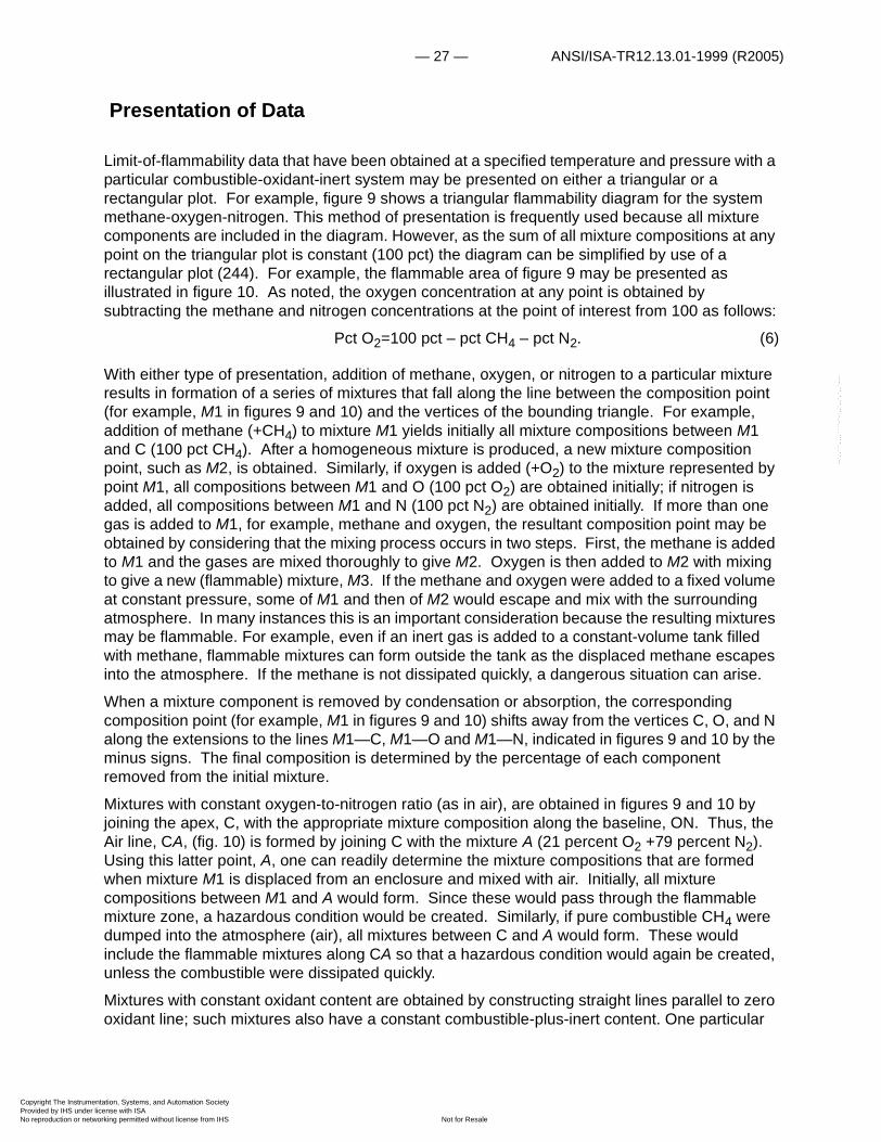
Limit-of-flammability data that have been obtained at a specified temperature and pressure with a particular combustible-oxidant-inert system may be presented on either a triangular or a rectangular plot. For example, figure 9 shows a triangular flammability diagram for the system methane-oxygen-nitrogen. This method of presentation is frequently used because all mixture components are included in the diagram. However, as the sum of all mixture compositions at any point on the triangular plot is constant (100 pct) the diagram can be simplified by use of a rectangular plot (244). For example, the flammable area of figure 9 may be presented as illustrated in figure 10. As noted, the oxygen concentration at any point is obtained by subtracting the methane and nitrogen concentrations at the point of interest from 100 as follows:
Pct O2=100 pct – pct CH4 – pct N2. (6)
With either type of presentation, addition of methane, oxygen, or nitrogen to a particular mixture results in formation of a series of mixtures that fall along the line between the composition point (for example, M1 in figures 9 and 10) and the vertices of the bounding triangle. For example, addition of methane (+CH4) to mixture M1 yields initially all mixture compositions between M1 and C (100 pct CH4). After a homogeneous mixture is produced, a new mixture composition point, such as M2, is obtained. Similarly, if oxygen is added (+O2) to the mixture represented by point M1, all compositions between M1 and O (100 pct O2) are obtained initially; if nitrogen is added, all compositions between M1 and N (100 pct N2) are obtained initially. If more than one gas is added to M1, for example, methane and oxygen, the resultant composition point may be obtained by considering that the mixing process occurs in two steps. First, the methane is added to M1 and the gases are mixed thoroughly to give M2. Oxygen is then added to M2 with mixing to give a new (flammable) mixture, M3. If the methane and oxygen were added to a fixed volume at constant pressure, some of M1 and then of M2 would escape and mix with the surrounding atmosphere. In many instances this is an important consideration because the resulting mixtures may be flammable. For example, even if an inert gas is added to a constant-volume tank filled with methane, flammable mixtures can form outside the tank as the displaced methane escapes into the atmosphere. If the methane is not dissipated quickly, a dangerous situation can arise.
When a mixture component is removed by condensation or absorption, the corresponding composition point (for example, M1 in figures 9 and 10) shifts away from the vertices C, O, and N along the extensions to the lines M1—C, M1—O and M1—N, indicated in figures 9 and 10 by the minus signs. The final composition is determined by the percentage of each component removed from the initial mixture.
Mixtures with constant oxygen-to-nitrogen ratio (as in air), are obtained in figures 9 and 10 by joining the apex, C, with the appropriate mixture composition along the baseline, ON. Thus, the Air line, CA, (fig. 10) is formed by joining C with the mixture A (21 percent O2 +79 percent N2). Using this latter point, A, one can readily determine the mixture compositions that are formed when mixture M1 is displaced from an enclosure and mixed with air. Initially, all mixture compositions between M1 and A would form. Since these would pass through the flammable mixture zone, a hazardous condition would be created. Similarly, if pure combustible CH4 were dumped into the atmosphere (air), all mixtures between C and A would form. These would include the flammable mixtures along CA so that a hazardous condition would again be created, unless the combustible were dissipated quickly.
Mixtures with constant oxidant content are obtained by constructing straight lines parallel to zero oxidant line; such mixtures also have a constant combustible-plus-inert content. One particular
entation, Systems, and Automation Society license with ISA
Not for Resaleworking permitted without license from IHS

ANSI/ISA-TR12.13.01-1999 (R2005) — 28 —
Copyright The InstrumProvided by IHS underNo reproduction or net
constant oxidant line is of special importance—the minimum constant oxidant line that is tangent to the flammability diagram or, in some cases, the one that passes through the extreme upper-limit-of-flammability value. This line gives the minimum oxidant (air, oxygen, chlorine, etc.) concentration needed to support combustion of a particular combustible at a specified temperature and pressure. In figures 9 and 10, the tangent line gives the minimum oxygen value (Min O2,12 volume-percent) required for flame propagation through methane-oxygen-nitrogen mixtures at 26°C and 1 atmosphere.
Another important construction line is that which gives the maximum nonflammable combustible-to-inert ratio (critical C/N). Mixtures along and below this line form nonflammable mixtures upon addition of oxidant. The critical C/N ratio is the slope of the tangent line from the origin (Figs. 9 and 10), 100 percent oxidant, to the lean side of the flammable mixtures curve. The reciprocal of this slope gives the minimum ratio of inert-to-combustible at which nonflammable mixtures form upon addition of oxidant. It is of interest in fire extinguishing.
Figure 9—Flammability Diagram for the System Methane-Oxygen-Nitrogen at Atmospheric Pressure and 26°C.
Flammablemixtures
Critical C/N
OXYGEN, volume-percent
MET
HANE
, volu
me-
perc
ent NITROGEN, volum
e-percent
Min O
100
-CH
+CH
M2
M1
M3 +N
-N -O
+O
+O
0
10
20
30
40
50
60
70
80
90
100
90 80 70 60 50 40 30 20 10 0100
90
80
70
60
50
40
30
20
10
0
Air
2
4
4
2
2 2
2
2
C
NO
--`,,```,,,,````-`-`,,`,,`,`,,`---
entation, Systems, and Automation Society license with ISA
Not for Resaleworking permitted without license from IHS
— 29 — ANSI/ISA-TR12.13.01-1999 (R2005)
Copyright The InstrumProvided by IHS underNo reproduction or net
Figure 10—Flammability Diagram for the System Methane-Oxygen-Nitrogen at Atmospheric Pressure and 26°C. (Data from fig. 9).
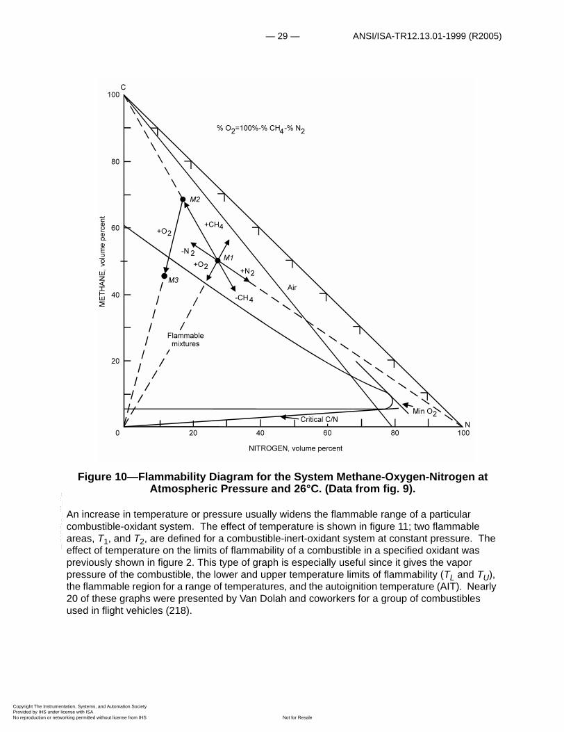
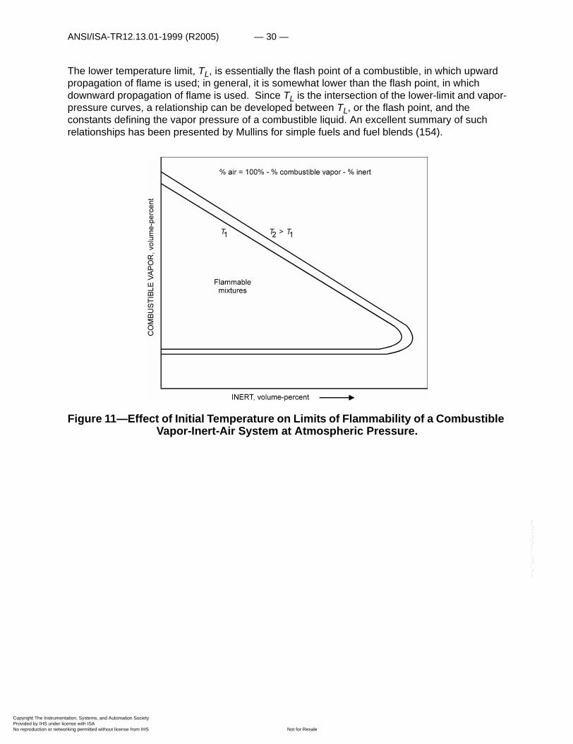
An increase in temperature or pressure usually widens the flammable range of a particular combustible-oxidant system. The effect of temperature is shown in figure 11; two flammable areas, T1, and T2, are defined for a combustible-inert-oxidant system at constant pressure. The effect of temperature on the limits of flammability of a combustible in a specified oxidant was previously shown in figure 2. This type of graph is especially useful since it gives the vapor pressure of the combustible, the lower and upper temperature limits of flammability (TL and TU), the flammable region for a range of temperatures, and the autoignition temperature (AIT). Nearly 20 of these graphs were presented by Van Dolah and coworkers for a group of combustibles used in flight vehicles (218).
--`,,```,,,,````-`-`,,`,,`,`,,`---
entation, Systems, and Automation Society license with ISA
Not for Resaleworking permitted without license from IHS
ANSI/ISA-TR12.13.01-1999 (R2005) — 30 —
Copyright The InstrumProvided by IHS underNo reproduction or net
--`,,```,,,,````-`-`,,`,,`,`,,`---
The lower temperature limit, TL, is essentially the flash point of a combustible, in which upward propagation of flame is used; in general, it is somewhat lower than the flash point, in which downward propagation of flame is used. Since TL is the intersection of the lower-limit and vapor-pressure curves, a relationship can be developed between TL, or the flash point, and the constants defining the vapor pressure of a combustible liquid. An excellent summary of such relationships has been presented by Mullins for simple fuels and fuel blends (154).
Figure 11—Effect of Initial Temperature on Limits of Flammability of a Combustible Vapor-Inert-Air System at Atmospheric Pressure.
entation, Systems, and Automation Society license with ISA
Not for Resaleworking permitted without license from IHS
— 31 — ANSI/ISA-TR12.13.01-1999 (R2005)
Copyright The InstrumProvided by IHS underNo reproduction or net
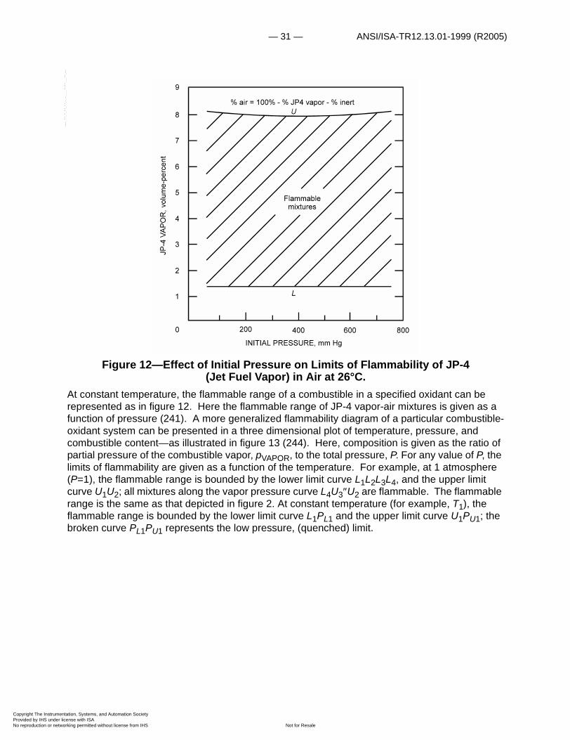
Figure 12—Effect of Initial Pressure on Limits of Flammability of JP-4 (Jet Fuel Vapor) in Air at 26°C.
At constant temperature, the flammable range of a combustible in a specified oxidant can be represented as in figure 12. Here the flammable range of JP-4 vapor-air mixtures is given as a function of pressure (241). A more generalized flammability diagram of a particular combustible-oxidant system can be presented in a three dimensional plot of temperature, pressure, and combustible content—as illustrated in figure 13 (244). Here, composition is given as the ratio of partial pressure of the combustible vapor, pVAPOR, to the total pressure, P. For any value of P, the limits of flammability are given as a function of the temperature. For example, at 1 atmosphere (P=1), the flammable range is bounded by the lower limit curve L1L2L3L4, and the upper limit curve U1U2; all mixtures along the vapor pressure curve L4U3�U2 are flammable. The flammable range is the same as that depicted in figure 2. At constant temperature (for example, T1), the flammable range is bounded by the lower limit curve L1PL1 and the upper limit curve U1PU1; the broken curve PL1PU1 represents the low pressure, (quenched) limit.
Flammablemixtures
% air = 100% - % JP4 vapor - % inert
1
0 200 400 600 800
2
3
4
5
6
7
8 U
L
9
JP-4
VAPO
R,v
olum
e-pe
rcen
t
INITIAL PRESSURE, mm Hg
--`,,```,,,,````-`-`,,`,,`,`,,`---
entation, Systems, and Automation Society license with ISA
Not for Resaleworking permitted without license from IHS

ANSI/ISA-TR12.13.01-1999 (R2005) — 32 —
Copyright The InstrumProvided by IHS underNo reproduction or net
Figure 13—Effect of Temperature and Pressure on Limits of Flammability of a Combustible Vapor in a Specified Oxidant.
The flammable range is the same as that depicted in figure 12. A similar range is defined at temperatures T2, T3, and T4 which are less than T1. However, at T3 and T4 the upper limit curves intersect the vapor pressure curves, so that no upper limits are found above U�3 and U�4. In other words, all compositions U�3U�3 and U�4L4 are flammable. The curve L4PLU�4U�3U2 defines the range of limit mixtures which are saturated with fuel vapor. Further, since L4 is the saturated lower limit mixture at one atmosphere, T4 is the flash point.
Some of the points considered in this and the previous section are illustrated in figure 14 (232). This is the flammability diagram for the system gasoline vapor-water vapor-air at 70°F (21°C) and
entation, Systems, and Automation Society license with ISA
Not for Resaleworking permitted without license from IHS
--`,,```,,,,````-`-`,,`,,`,`,,`---
— 33 — ANSI/ISA-TR12.13.01-1999 (R2005)
Copyright The InstrumProvided by IHS underNo reproduction or net
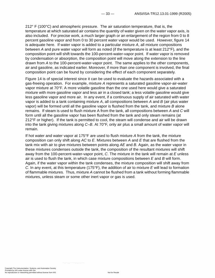
212° F (100°C) and atmospheric pressure. The air saturation temperature, that is, the temperature at which saturated air contains the quantity of water given on the water vapor axis, is also included. For precise work, a much larger graph or an enlargement of the region from 0 to 8 percent gasoline vapor and from 0 to 30 percent water vapor would be used. However, figure 14 is adequate here. If water vapor is added to a particular mixture A, all mixture compositions between A and pure water vapor will form as noted (if the temperature is at least 212°F), and the composition point will shift towards the 100-percent-water-vapor point. If water vapor is removed by condensation or absorption, the composition point will move along the extension to the line drawn from A to the 100-percent-water-vapor point. The same applies to the other components, air and gasoline, as indicated earlier. Moreover, if more than one component is involved, the final composition point can be found by considering the effect of each component separately.
Figure 14 is of special interest since it can be used to evaluate the hazards associated with a gas-freeing operation. For example, mixture A represents a saturated gasoline vapor-air-water vapor mixture at 70°F. A more volatile gasoline than the one used here would give a saturated mixture with more gasoline vapor and less air in a closed tank; a less volatile gasoline would give less gasoline vapor and more air. In any event, if a continuous supply of air saturated with water vapor is added to a tank containing mixture A, all compositions between A and B (air plus water vapor) will be formed until all the gasoline vapor is flushed from the tank, and mixture B alone remains. If steam is used to flush mixture A from the tank, all compositions between A and C will form until all the gasoline vapor has been flushed from the tank and only steam remains (at 212°F or higher). If the tank is permitted to cool, the steam will condense and air will be drawn into the tank giving mixtures along C–B. At 70°F, only air plus a small amount of water vapor will remain.
If hot water and water vapor at 175°F are used to flush mixture A from the tank, the mixture composition can only shift along AC to E. Mixtures between A and E that are flushed from the tank mix with air to give mixtures between points along AE and B. Again, as the water vapor in these mixtures condenses outside the tank, the composition of the resultant mixtures will shift away from the 100-percent-water-vapor point, C. The mixture in the tank will remain at E unless air is used to flush the tank, in which case mixture compositions between E and B will form. Again, if the water vapor within the tank condenses, the mixture composition will shift away from C. In any event, at this temperature (175°F), the addition of air to mixture E will lead to formation of flammable mixtures. Thus, mixture A cannot be flushed from a tank without forming flammable mixtures, unless steam or some other inert vapor or gas is used.
entation, Systems, and Automation Society license with ISA
Not for Resaleworking permitted without license from IHS
--`,,```,,,,````-`-`,,`,,`,`,,`---
ANSI/ISA-TR12.13.01-1999 (R2005) — 34 —
Copyright The InstrumProvided by IHS underNo reproduction or net
Figure 14—Flammability Diagram for the System Gasoline Vapor-Water Vapor-Air at 70°F (21°C) and at 212°F (100°C) and Atmospheric Pressure.
Deflagration and Detonation Processes
Once a flammable mixture is ignited, the resulting flame, if not extinguished, will either attach itself to the ignition source or propagate from it. If it propagates from the source, the propagation rate will be either subsonic (deflagration) or supersonic (detonation) relative to the unburned gas. If it is subsonic, the pressure will equalize at the speed of sound throughout the enclosure in which combustion is taking place so that the pressure drop across the flame (reaction) front will be relatively small. If the rate is supersonic, the rate of pressure equalization will be less than the propagation rate and there will be an appreciable pressure drop across the flame front. Moreover, with most combustible-air mixtures, at ordinary temperatures, the ratio of the peak-to-initial pressure within the enclosure will seldom exceed about 8:1 in the former, but may be more than 40:1 in the latter case. The pressure buildup is especially great when detonation follows a
D
entation, Systems, and Automation Society license with ISA
Not for Resaleworking permitted without license from IHS
--`,,```,,,,````-`-`,,`,,`,`,,`---

— 35 — ANSI/ISA-TR12.13.01-1999 (R2005)
Copyright The InstrumProvided by IHS underNo reproduction or net
--`,,
large pressure rise due to deflagration. The distance required for a deflagration to transit to a detonation depends on the flammable mixture, temperature, pressure, the enclosure, and the ignition source. With a sufficiently powerful ignition source, detonation may occur immediately upon ignition, even in the open. However, the ignition energy required to initiate a detonation is usually many orders of magnitude greater than that required to initiate a deflagration (32, 249).
DEFLAGRATION
Where a deflagration occurs in a spherical enclosure of volume V with central ignition, the approximate pressure rise �P at any instant t after ignition is given by the expressions:
(7)
and
(8)
where K is a constant, Su is the burning velocity, P1 is the initial pressure Pm is the maximum pressure, T1 is the initial temperature, n1 is the number of moles of gas in the initial mixture, nb is the number of moles of gas in the burned gases, is the average molecular weight of the initial mixture, is the average molecular weight of the burned gases, and Tb is the final (adiabatic) temperature of the products. With other enclosures, or with noncentral ignition, the flame front is disturbed by the walls before combustion is completed, so that calculated pressure cannot be expected to approximate actual pressure. Even with spherical enclosures, the flame front is not actually spherical, so that the walls tend to disturb the flame before combustion is complete (118, 130). A graph of the pressure developed by the combustion of a stoichiometric methane-air mixture (central ignition) in a 19.7 cm diameter, 9-liter cylinder is given in figure 15. The calculated pressure for a 9-liter sphere is included for comparison; K in equation (7) was evaluated from the experimental curve at 70 milliseconds. The calculated curve follows the experimental curve closely about 75 milliseconds, when the latter curve has a break. This suggests that the flame front was affected by the cylinder walls in such a way that the rate of pressure rise decreased, and the experimental curve fell below the calculated curve. Further, since the combustion gases were being cooled, the maximum pressure fell below the calculated value. The minimum elapsed time (in milliseconds) required to reach the maximum pressure appears to be about for the paraffin hydrocarbons and fuel blends such as gasoline; V is the volume in cubic feet in this case.
DETONATION
Wolfson and Dunn (52, 230) have expressed the pressure ratio P2/P1 across a detonation front as
�P KP1Su
3t3
V---------= Pm,�
Pm P1nbTbn1T1----------- P1
M1Tb
MbT1-------------==
M1Mb
75 V3
entation, Systems, and Automation Society license with ISA
Not for Resaleworking permitted without license from IHS
```,,,,````-`-`,,`,,`,`,,`---

ANSI/ISA-TR12.13.01-1999 (R2005) — 36 —
Copyright The InstrumProvided by IHS underNo reproduction or net
(9)
where �2 is the specific heat ratio of the burned gases, �1 is the specific heat ratio of the initial mixture, and M1, is the Mach number of the detonation wave with respect to the initial mixture. M1 is given in terms of the temperatures T and molecular weights W of the initial and final mixtures by the expression:
. (10)
Wolfson and Dunn have developed generalized charts that simplify the operations involved in obtaining the pressure ratio as well as the density and temperature/molecular weight ratios across the detonation wave and the energy release in the detonation wave.
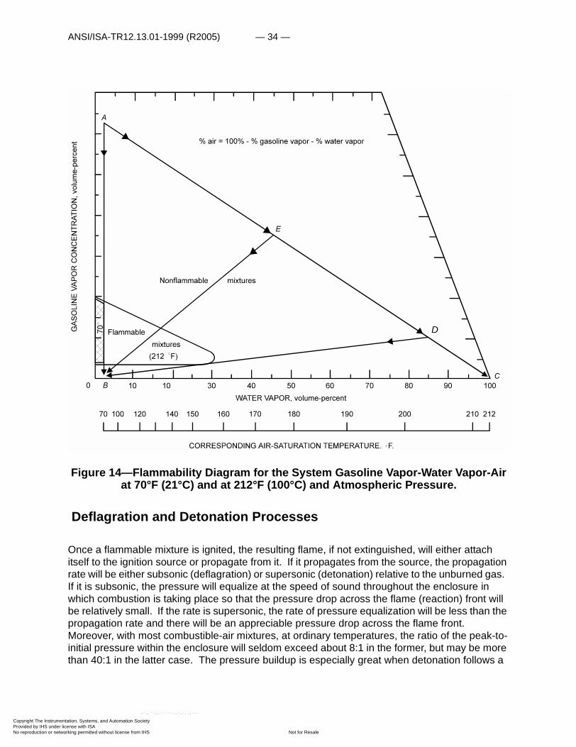
Many investigators have measured and calculated detonation and reflected pressures resulting from detonation waves (54, 57, 204). Figure 16 from the data of Stoner and Bleakney (204) gives the detonation velocity, the static or detonation pressure, and the reflected pressure developed by a detonation wave propagating through hydrogen-oxygen mixtures at atmospheric pressure and 18°C.
Figure 15—Pressure Produced by Ignition of a 9.6 Volume-Percent Methane-Air Mixture in a 9-Liter Cylinder (Experimental).
P2P1------ 1
2 1+-------------- 1M12 1+ �,=
1M12 1+ �
2
1M12-----------------------------
2 1+ �2T2W12T1W2
-----------------------------------=
Calculated(9-liter sphere)
Experimental(9-liter cylinder)
ELAPSED TIME, milliseconds0
20
40
60
80
100Pm
40 80 120 160
PRES
SUR
ER
ISE,
psi
--`,,```,,,,````-`-`,,`,,`,`,,`---
entation, Systems, and Automation Society license with ISA
Not for Resaleworking permitted without license from IHS
— 37 — ANSI/ISA-TR12.13.01-1999 (R2005)
Copyright The InstrumProvided by IHS underNo reproduction or net
BLAST PRESSURE
The pressures produced by a deflagration or a detonation are often sufficient to demolish an enclosure (reactor, building, etc.). As noted, a deflagration can produce pressure rises in excess of 8:1, and pressure rises of 40:1 (reflected pressure) can accompany a detonation. As ordinary structures can be demolished by pressure differentials of 2 or 3 psi, it is not surprising that even reinforced concrete structures have been completely demolished by explosions of near-limit flammable mixtures.
Figure 16—Detonation Velocity, V; Static Pressure, Ps; and Reflected Pressure, Pr, Developed by a Detonation Wave Propagating Through Hydrogen-Oxygen
Mixtures in a Cylindrical Tube at Atmospheric Pressure and 18°C.
Jacobs and coworkers have studied the damage potential of detonation waves in great detail (91, 170). They have considered the principles involved in rupturing of pipes and vessels by detonations and the relevance of engineering and metallurgical data to explosions. More recently, Randall and Ginsburg (171) have investigated bursting of tubular specimens at ordinary and reduced temperatures. They found that the detonation pressure required to burst such specimens was, in general, slightly higher than the corresponding static-bursting pressure. Ductility of the test specimen appeared to have little effect on the bursting pressure, but ductility increased the strength of pipes containing notches or other stress raisers.
(theoretical)
(experimental)
(experimental)
P
V
r
,m/s
ecV ,a
tmP
H , volume-percent2
Pr
Ps
1,50020 30 40 50 60 70 80 90
0
5
10
20
25
30
35
40
45
50
152,000
2,500
3,000
3,500
entation, Systems, and Automation Society license with ISA
Not for Resaleworking permitted without license from IHS
--`,,```,,,,````-`-`,,`,,`,`,,`---

ANSI/ISA-TR12.13.01-1999 (R2005) — 38 —
Copyright The InstrumProvided by IHS underNo reproduction or net
When a detonation causes an enclosure to fail, a shock wave may propagate outward at a rate determined by characteristics of the medium through which it is transmitted, and the available energy. If the shock velocity, V, is known, the resulting overpressure, (P – Po), is given by the expression (204)
, (11)
where ��is the ratio of specific heats, and a is the velocity of sound in the medium through which the shock wave passes. The approximate damage potential can be assessed from the data in table 1 (217).
In conducting experiments in which blast pressures may be generated, special precautions must be taken to protect the personnel and equipment from blast and missiles. Browne, Hileman, and Weger (16) have reviewed the design criteria for suitable barricades. Other authors have considered the design of suitable laboratories and structures to prevent fragment damage to surrounding areas (44, 174, 203, 220).
Table 1 — Conditions of failure of peak over pressure-sensitive elements (217)
Preventive Measures
INERTING
In principle, a gas explosion hazard can be eliminated by removing either all flammable mixtures or all ignition sources (23, 240). However, this is not always practical, as many industrial operations require the presence of flammable mixtures,and actual or potential ignition sources. Accordingly, special precautions must be taken to minimize the damage that would result if an accidental ignition were to occur. One such precaution involves the use of explosive actuators
Structural element Failure Approximate incident blast overpressure (psi)
Glass windows, large and small. Usually shattering, occasional frame failure.
0.5-1.0
Corrugated asbestos siding. Shattering. 1.0-2.0
Corrugated steel or aluminum paneling.
Connection failure, followed by buckling.
1.0-2.0
Wood siding panels, standard house construction.
Usually failure occurs at main connections, allowing a whole panel to be blown in.
1.0-2.0
Concrete or cinderblock wall panels, 8 or 12 inches thick (not reinforced).
Shattering of the wall. 2.0-3.0
Brick wall panel, 8 or 12 inches thick (not reinforced).
Shearing and flexure failures. 7.0-8.0
P Po Po2 1–----------- V
a--- 1–=–
entation, Systems, and Automation Society license with ISA
Not for Resaleworking permitted without license from IHS
--`,,```,,,,````-`-`,,`,,`,`,,`---

— 39 — ANSI/ISA-TR12.13.01-1999 (R2005)
Copyright The InstrumProvided by IHS underNo reproduction or net
--`,,```,,,,````-`-`,,`,,`,`,,`---
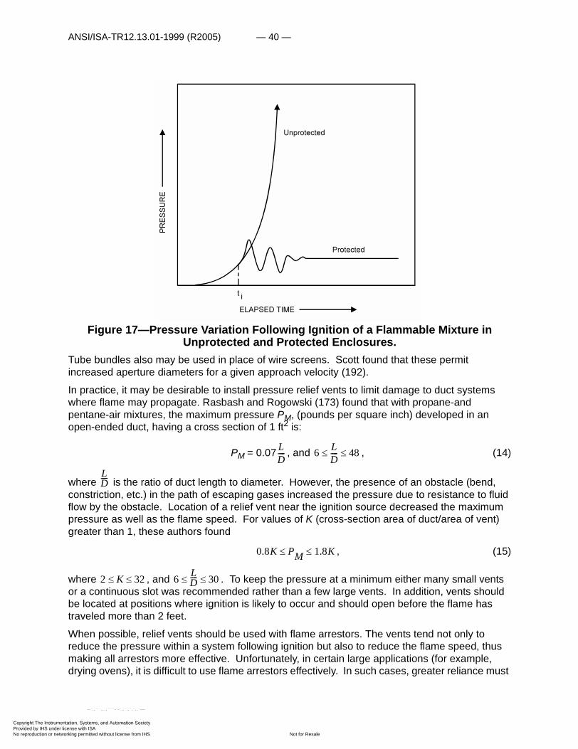
which attempt to add inert material at such a rate that an explosive reaction is quenched before structural damage occurs (70, 72). Figure 17 shows how the pressure varies with and without such protection. In the latter case, the pressure rise is approximately a cubic function of time, as noted earlier. In the former case, inert is added when the pressure or the rate of pressure rise exceeds a predetermined value. This occurs at the time ti in figure 17 when the explosive actuators function to add the inert. As noted, the pressure increases momentarily above the value found in the unprotected case and then falls rapidly as the combustion reaction is quenched by the inert.
FLAME ARRESTORS AND RELIEF DIAPHRAGMS
Inert atmospheres must be used when not even a small explosive reaction can be tolerated. However, when the ignition of a flammable mixture would create little hazard if the burning mixture were vented, flame arrestors and relief diaphragms could be used effectively. The design of such systems is determined by the size and strength of the confining vessels, ducts, etc.
In recent studies of the efficiency of wire gauze and perforated block arrestors (161, 162), Palmer found the velocity of approach of the flame to be the major factor in determining whether flame passed through an arrestor. For these two types of arrestors, he found the critical approach velocity to be
, (12)
and
, (13)
where k is the thermal conductivity of the gas; m is the mesh width; Th is the mean bulk temperature of the flame gases through the arrestor; To is the initial temperature of the arrestor; Q is the heat lost by unit area of flame; xo is the thickness of the flame propagating at the burning velocity, S; d is the diameter of an aperture; A� is the area of a hole in unit area of the arrestor face; and t is the arrestor thickness.
Equations (12) and (13) can be used to determine the mesh width or aperture diameter needed to stop a flame having a particular approach velocity. In practice, application of these equations assumes a knowledge of the flame speed in the system of interest. Some useful data have been made available by Palmer and Rasbash and Rogowski (172, 173), as well as by Jost (118) and Lewis and von Elbe (130).
V�1.75k Th To– �
m0.9Q xo ------------------------------------=
V9.6kA�t Th To– �
d2Q xo -----------------------------------------=
entation, Systems, and Automation Society license with ISA
Not for Resaleworking permitted without license from IHS
ANSI/ISA-TR12.13.01-1999 (R2005) — 40 —
Copyright The InstrumProvided by IHS underNo reproduction or net
Figure 17—Pressure Variation Following Ignition of a Flammable Mixture in Unprotected and Protected Enclosures.
Tube bundles also may be used in place of wire screens. Scott found that these permit increased aperture diameters for a given approach velocity (192).
In practice, it may be desirable to install pressure relief vents to limit damage to duct systems where flame may propagate. Rasbash and Rogowski (173) found that with propane-and pentane-air mixtures, the maximum pressure PM, (pounds per square inch) developed in an open-ended duct, having a cross section of 1 ft2 is:
PM = 0.07 , and , (14)
where is the ratio of duct length to diameter. However, the presence of an obstacle (bend, constriction, etc.) in the path of escaping gases increased the pressure due to resistance to fluid flow by the obstacle. Location of a relief vent near the ignition source decreased the maximum pressure as well as the flame speed. For values of K (cross-section area of duct/area of vent) greater than 1, these authors found
, (15)
where , and . To keep the pressure at a minimum either many small vents or a continuous slot was recommended rather than a few large vents. In addition, vents should be located at positions where ignition is likely to occur and should open before the flame has traveled more than 2 feet.
When possible, relief vents should be used with flame arrestors. The vents tend not only to reduce the pressure within a system following ignition but also to reduce the flame speed, thus making all arrestors more effective. Unfortunately, in certain large applications (for example, drying ovens), it is difficult to use flame arrestors effectively. In such cases, greater reliance must
LD---- 6 L
D---- 48� �
LD----
0.8K PM 1.8K� �
2 K 32� � 6 LD---- 30� �
entation, Systems, and Automation Society license with ISA
Not for Resaleworking permitted without license from IHS
--`,,```,,,,````-`-`,,`,,`,`,,`---
— 41 — ANSI/ISA-TR12.13.01-1999 (R2005)
Copyright The InstrumProvided by IHS underNo reproduction or net
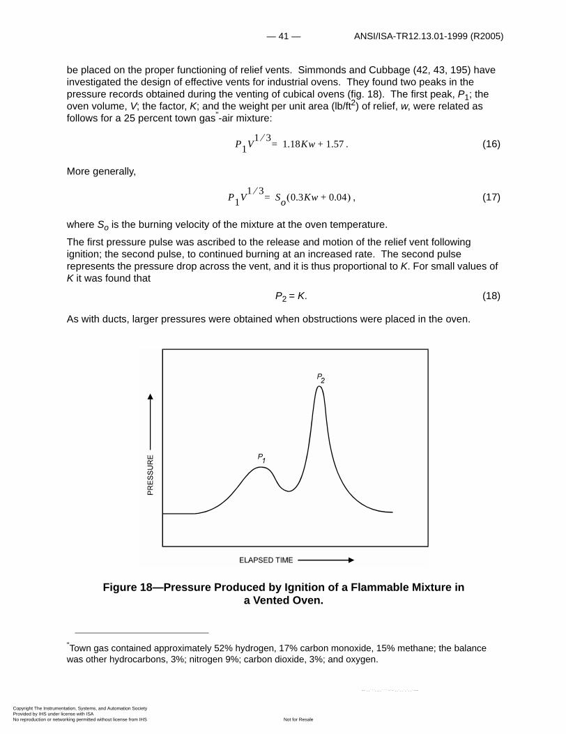
be placed on the proper functioning of relief vents. Simmonds and Cubbage (42, 43, 195) have investigated the design of effective vents for industrial ovens. They found two peaks in the pressure records obtained during the venting of cubical ovens (fig. 18). The first peak, P1; the oven volume, V; the factor, K; and the weight per unit area (lb/ft2) of relief, w, were related as follows for a 25 percent town gas"-air mixture:
. (16)
More generally,
, (17)
where So is the burning velocity of the mixture at the oven temperature.
The first pressure pulse was ascribed to the release and motion of the relief vent following ignition; the second pulse, to continued burning at an increased rate. The second pulse represents the pressure drop across the vent, and it is thus proportional to K. For small values of K it was found that
P2 = K. (18)
As with ducts, larger pressures were obtained when obstructions were placed in the oven.
Figure 18—Pressure Produced by Ignition of a Flammable Mixture in a Vented Oven.
"Town gas contained approximately 52% hydrogen, 17% carbon monoxide, 15% methane; the balance was other hydrocarbons, 3%; nitrogen 9%; carbon dioxide, 3%; and oxygen.
P1V1 3 1.18Kw 1.57+=
P1V1 3 So 0.3Kw 0.04+ �=
entation, Systems, and Automation Society license with ISA
Not for Resaleworking permitted without license from IHS
--`,,```,,,,````-`-`,,`,,`,`,,`---
ANSI/ISA-TR12.13.01-1999 (R2005) — 42 —
Copyright The InstrumProvided by IHS underNo reproduction or net
--`,,```,,,,````-`-`,,`,,`,`,,`---
In designing explosion reliefs for ovens, Simmonds and Cubbage pointed out that (1) the reliefs should be constructed in such a way that they do not form dangerous missiles if an explosion occurs; (2) the weight of the relief must be small so that it opens before the pressure builds up to a dangerous level; (3) the areas and positions of relief openings must be such that the explosion pressure is not excessive; (4) sufficient free space must be utilized around the oven to permit satisfactory operation of the relief and minimize risk of burns to personnel; and (5) oven doors should be fastened securely so that they do not open in the event of an explosion.
Burgoyne and Wilson have presented the results of an experimental study of pentane vapor-air explosions in vessels of 60- and 200-cubic-foot volume (30). They found the rates of pressure rise greater than could be predicted from laminar burning velocity data, so that the effect of a relief area in lowering the peak pressure was less than expected. All experiments were conducted at an initial pressure of 1 atmosphere. Vent data for use at higher initial pressures are summarized in an article by Block (10); a code for designing pressure relief systems has been proposed in this article. Other authors have considered the effects of temperature and characteristics of the flammable mixture on vent requirements (14, 35, 38, 45, 46, 134, 145, 168, 221).
Flammability Characteristics
The flammability data (limits of flammability, flash point, ignition temperature and burning velocity) of the various chemical families exhibit many similarities. Accordingly, the data presented here are grouped under the various commercially important families, blends, and miscellaneous combustibles.
PARAFFIN HYDROCARBONS (CnH2n+2)
Limits in Air
Lower and upper limits of flammability at 25°C (or at the temperature noted) and 1 atmosphere (L25 and U25) for many members of the paraffin hydrocarbon series are given in table 2, together with the molecular weight, M, vapor specific gravity, sp gr, stoichiometric composition in air, Cst (appendix B) and heat of combustion, �Hc (183). At room temperature and atmospheric or reduced pressure, the lower limits of flammability of most of this series fall in the range from 45 to 50 mg combustible vapor per liter of air at standard conditions, that is, 0°C and 760 mm Hg (0.045 to 0.050 oz combustible vapor per cubic foot of air) (247). This is illustrated in figure 19 in which some lower limits of flammability are plotted against molecular weight; except for methane, ethane, and propane all limit values fall in a band between concentrations of approximately 45 and 50 mg/lr.
The following expression may be used to convert from a lower limit L in volume-percent of vapor in the vapor-air mixture to one in milligrams of combustible, per liter of air at standard conditions:
, (19)L mg1-------� �
� � L (vol pct)
100 L (vol pct)–� � sp vol 1mg-------
--------------------------------------------------------------------------=
entation, Systems, and Automation Society license with ISA
Not for Resaleworking permitted without license from IHS
— 43 — ANSI/ISA-TR12.13.01-1999 (R2005)
Copyright The InstrumProvided by IHS underNo reproduction or net
--`,,```,,,,````-`-`,,`,,`,`,,`---
specific volume being volume of combustible vapor per milligram of combustible. At standard conditions (0°C and 760 mm Hg) this is about 22.414/1,000M, where M is the molecular weight of the combustible. Since L (vol pct) of most members of this series is much less than 100 percent, the lower limit can be expressed as
. (20)
At any specified temperature, the ratio of the lower limit to the amount of combustible needed for complete combustion, Cst, also is approximately constant. This was first noted by Jones (95) and later by Lloyd (133), who found that for paraffin hydrocarbons at about 25°C,
. (21)
For the complete combustion of the paraffin hydrocarbons, we have:
, (22)
so that in air
, (23)
where 4.773 is the reciprocal of 0.2095, the molar concentration of oxygen in dry air. The values of Cst (appendix B) are included in table 2. By weight these become
, (24)
or
. (25)
L mg1-------� �
� � 0.45ML (vol pct)�
L25� 0.55Cst�
CnH2n 2+ 1.5n 0.5+ �O2 nCO� 2 n 1+ �H2O+ +
Cst100
1 4.773 1.5n 0.5+ �+---------------------------------------------------- vol pct=
Cst1000 12.01n� 1.008 2n 2 � �+ +
22.414 4.773 1.5n 0.5+ ��----------------------------------------------------------------------------mg
1-------=
Cst 9.34 14.03n 2.02+1.5n 0.5+--------------------------------- mg
1-------=
entation, Systems, and Automation Society license with ISA
Not for Resaleworking permitted without license from IHS

ANSI/ISA-TR12.13.01-1999 (R2005) — 44 —
Copyright The InstrumProvided by IHS underNo reproduction or net
Figure 19—Effect of Molecular Weight on Lower Limits of Flammability of Paraffin Hydrocarbons at 25°C.
entation, Systems, and Automation Society license with ISA
Not for Resaleworking permitted without license from IHS
--`,,```,,,,````-`-`,,`,,`,`,,`---
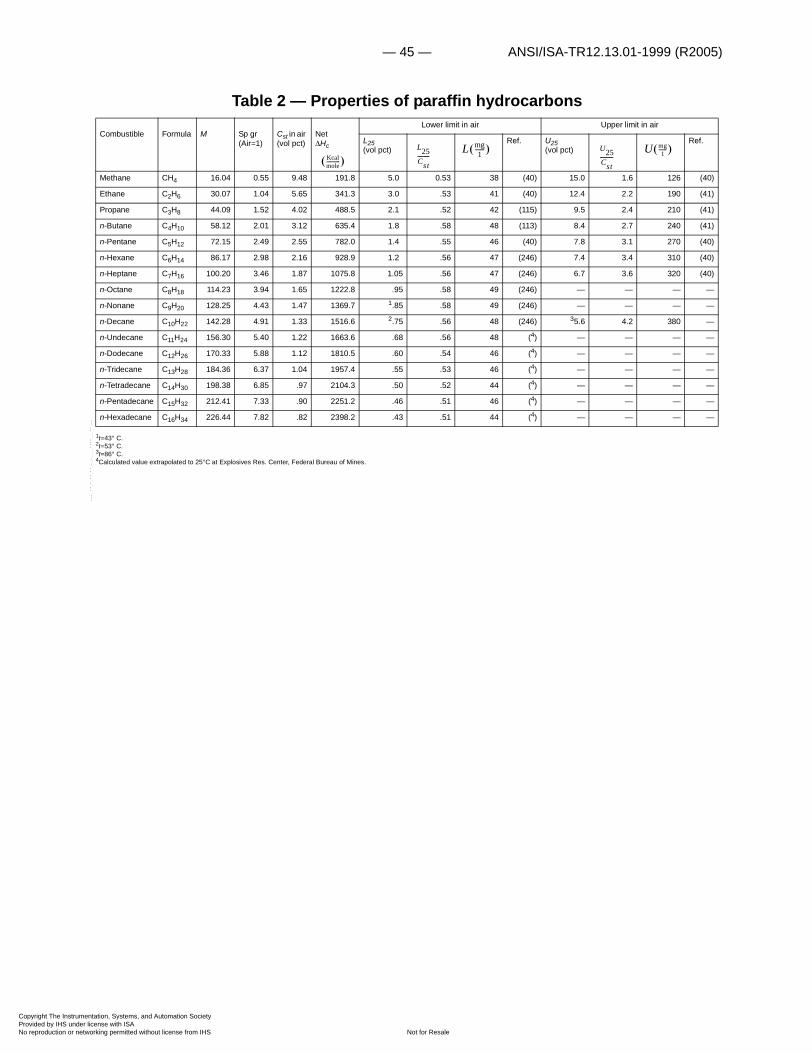
— 45 — ANSI/ISA-TR12.13.01-1999 (R2005)
Copyright The InstrumProvided by IHS underNo reproduction or net
Table 2 — Properties of paraffin hydrocarbons
1t=43° C.2t=53° C.3t=86° C.4Calculated value extrapolated to 25°C at Explosives Res. Center, Federal Bureau of Mines.
Combustible Formula M Sp gr (Air=1)
Cst in air (vol pct)
Net�Hc
Lower limit in air Upper limit in air
L25 (vol pct)
Ref. U25 (vol pct)
Ref.
Methane CH4 16.04 0.55 9.48 191.8 5.0 0.53 38 (40) 15.0 1.6 126 (40)
Ethane C2H6 30.07 1.04 5.65 341.3 3.0 .53 41 (40) 12.4 2.2 190 (41)
Propane C3H8 44.09 1.52 4.02 488.5 2.1 .52 42 (115) 9.5 2.4 210 (41)
n-Butane C4H10 58.12 2.01 3.12 635.4 1.8 .58 48 (113) 8.4 2.7 240 (41)
n-Pentane C5H12 72.15 2.49 2.55 782.0 1.4 .55 46 (40) 7.8 3.1 270 (40)
n-Hexane C6H14 86.17 2.98 2.16 928.9 1.2 .56 47 (246) 7.4 3.4 310 (40)
n-Heptane C7H16 100.20 3.46 1.87 1075.8 1.05 .56 47 (246) 6.7 3.6 320 (40)
n-Octane C8H18 114.23 3.94 1.65 1222.8 .95 .58 49 (246) — — — —
n-Nonane C9H20 128.25 4.43 1.47 1369.7 1.85 .58 49 (246) — — — —
n-Decane C10H22 142.28 4.91 1.33 1516.6 2.75 .56 48 (246) 35.6 4.2 380 —
n-Undecane C11H24 156.30 5.40 1.22 1663.6 .68 .56 48 (4) — — — —
n-Dodecane C12H26 170.33 5.88 1.12 1810.5 .60 .54 46 (4) — — — —
n-Tridecane C13H28 184.36 6.37 1.04 1957.4 .55 .53 46 (4) — — — —
n-Tetradecane C14H30 198.38 6.85 .97 2104.3 .50 .52 44 (4) — — — —
n-Pentadecane C15H32 212.41 7.33 .90 2251.2 .46 .51 46 (4) — — — —
n-Hexadecane C16H34 226.44 7.82 .82 2398.2 .43 .51 44 (4) — — — —
Kcalmole------------� �
L25Cst---------
L mg1
-------� � U25Cst----------
U mg1
-------� �
--`,,```,,,,````-`-`,,`,,`,`,,`---
entation, Systems, and Automation Society license with ISA
Not for Resaleworking permitted without license from IHS
ANSI/ISA-TR12.13.01-1999 (R2005) — 46 —
Copyright The InstrumProvided by IHS underNo reproduction or net
--`,,```,,,,````-`-`,,`,,`,`,,`---
Thus,
mg/1, n� � (26)
Combining this equation with equation (21), we have
, (27)
for paraffin hydrocarbons, except methane, ethane, and propane. Substitution of this value into equation (20) gives
. (28)
The following expression may be used to convert a lower limit value in volume-percent to a fuel-air (weight) ratio:
. (29)
The reciprocal expression gives the air-fuel (weight) ratio:
. (30)
As noted, the lower limits given in figure 19 were determined at room temperature and atmospheric or reduced pressure. Lower limits vary with temperature as shown for methane in figure 20. The limit values obtained with upward propagation of flame (21) fall fairly close to a straight line that passes through the lower limit value at 25°C and the flame temperature (1,225°C). This is in accordance with the White criterion that the flame temperature is constant at the lower limit (222). The data obtained by White with downward propagation of flame fall along a line parallel to the line through the limit values obtained with upward propagation. Taking the value 1,300°C as the approximate flame temperature for the paraffin hydrocarbon series (55), and using the lower limit values at room temperature in table 2, the limits of the first 10 paraffin hydrocarbons are represented as in figures 21 and 22. Figure 21 gives the lower limits in volume-percent and figure 22 in milligrams per liter. By weight, the lower limits of most members of this series again fall in a fairly narrow band ("higher hydrocarbons" region). Individual adiabatic flame temperatures can be determined for lower limit mixtures using the data in table 2 and appendix C (55).
The straight lines of figures 21 and 22 are given by:
, (31)
or
. (32)
Cst 87�
L25�mg1-------� �
� � 48 mg1-------� �
� ��
L25�(vol pct) 107M---------�
L F A � M28.96------------- L (vol pct)
100 L (vol pct)–----------------------------------------=
L A F � 28.96M
------------- 100L (vol pct)------------------------- 1–=
Lt L25�L25�
1300� 25�–-----------------------------– t 25�– �=
LtL25�---------- 1 0.000784– t 25�– �=
entation, Systems, and Automation Society license with ISA
Not for Resaleworking permitted without license from IHS

— 47 — ANSI/ISA-TR12.13.01-1999 (R2005)
Copyright The InstrumProvided by IHS underNo reproduction or net
They are described in more general terms by a plot of Lt,/L25° against the temperature (fig. 23, solid line).
Figure 20—Effect of Temperature on Lower Limit of Flammability of Methane in Air at Atmospheric Pressure.
These data are also correlated fairly well with the modified Burgess-Wheeler Law suggested by Zabetakis, Lambiris, and Scott (242):
, (33)
where t is the temperature in °C and �Hc is the net heat of combustion in kilocalories per mole. Then,
. (34)
Substituting the value 1,040 for L25°·�Hc obtained by Spakowski (201), we have
Lt L25�0.75�Hc----------– t 25�– �=
LtL25�---------- 1 0.75
L25� �Hc�-------------------------– t 25�– �=
--`,,```,,,,````-`-`,,`,,`,`,,`---
entation, Systems, and Automation Society license with ISA
Not for Resaleworking permitted without license from IHS

ANSI/ISA-TR12.13.01-1999 (R2005) — 48 —
Copyright The InstrumProvided by IHS underNo reproduction or net
, (35)
which is also given in figure 23 for a limited temperature range with the broken line.
Only the lower limit at 25°C and atmospheric pressure is needed to use figure 23. For example, assuming a constant flame temperature, the ratio Lt /L25° at 600°C is 0.55. The calculated lower limit of methane at 600°C therefore is 5.0 x 0.55, or 2.75 volume-percent. The same value can be obtained directly from figure 21. From the modified Burgess-Wheeler Law curve, Lt /L25°=0.585 at 600°C, so that L600°=2.92 volume-percent.
Figure 21—Effect of Temperature on Lower Limits of Flammability of 10 Paraffin Hydrocarbons in Air at Atmospheric Pressure.
Limit-of-flammability measurements are complicated by surface and vapor-phase reactions that occur at temperatures above the autoignition temperature. For example, Burgoyne and Hirsch (25) have shown that methane-air mixtures containing up to 5 percent methane burn readily at
LtL25�---------- 1 0.000721– t 25�– �=
entation, Systems, and Automation Society license with ISA
Not for Resaleworking permitted without license from IHS
--`,,```,,,,````-`-`,,`,,`,`,,`---

— 49 — ANSI/ISA-TR12.13.01-1999 (R2005)
Copyright The InstrumProvided by IHS underNo reproduction or net
--`,,```,,,,````-`-`,,`,,`,`,,`---
1,000° C. Experiments were conducted with mixtures containing as little as 0.5 percent methane; figure 20 predicts that a flame would not propagate through such a mixture.
Flammability experiments at elevated temperatures indicate that in the absence of cool flames (87, 88), the upper limit also increases linearly with temperature. The effect of temperature appears to be fairly well correlated by the modified Burgess-Wheeler law:
. (36)
If we assume that the heat release at the upper limit is equal to that at the lower limit, then
. (37)
A plot of Ut /U25° against temperature (fig.24) was used to compare recent experimental values of Rolingson and coworkers (182) for methane-air mixtures at 15 psig with those predicted by the modified Burgess-Wheeler law. The experimental and calculated upper limits are given in table 3 together with the difference, Ucalc – Uexper. In each case, the difference is less than 4 percent of the experimental value, which is approximately within the limit of experimental error. Earlier experiments of White (222) at temperatures to 400° C, with downward flame propagation, also are represented quite adequately by equation (37). For example, White found that the upper limit of pentane in air (downward propagation) increased linearly from 4.50 volume-percent at about 17° C to 5.35 volume-percent at 300° C. The ratio of 5.35: 4.50 is 1.17, which compares quite well with U300°/U25°�1.20 obtained from figure 24.
Ut U25�0.· 75�Hc---------- t 25�– �+=
UtU25�----------- 1 0.000721 t 25�– �+=
entation, Systems, and Automation Society license with ISA
Not for Resaleworking permitted without license from IHS

ANSI/ISA-TR12.13.01-1999 (R2005) — 50 —
Copyright The InstrumProvided by IHS underNo reproduction or net
Figure 22—Effect of Temperature on Lower Limits of Flammability of 10 Paraffin Hydrocarbons in Air at Atmospheric Pressure by Weight.
entation, Systems, and Automation Society license with ISA
Not for Resaleworking permitted without license from IHS
--`,,```,,,,````-`-`,,`,,`,`,,`---

— 51 — ANSI/ISA-TR12.13.01-1999 (R2005)
Copyright The InstrumProvided by IHS underNo reproduction or net
--`,,```,,,,````-`-`,,`,,`,`,,`---
Given the vapor pressure curve and the lower limit of flammability, the lower temperature limit or approximate flash point of a combustible can be calculated from either equation (32) or (35) (218). Approximate flash points were obtained previously, using only the vapor pressure curve and the lower limit at ordinary or elevated temperatures (154). The values obtained with this procedure are somewhat low because the lower limit at any temperature above the flash point is less than at the flash point. The lower temperature limits of paraffin hydrocarbon at atmospheric pressure are given in table 4.
Table 3 — Upper flammability limits, U, of methane-air mixtures at 15 psig.
1 (182).
Temperature (°C) Uexper1 (vol percent) Ucalc (vol percent)
Ucalc–Uexper (vol percent)
25 15.5 15.5 0
100 16.3 16.4 .1
200 17.0 17.5 .5
300 17.9 18.6 .7
entation, Systems, and Automation Society license with ISA
Not for Resaleworking permitted without license from IHS

ANSI/ISA-TR12.13.01-1999 (R2005) — 52 —
Copyright The InstrumProvided by IHS underNo reproduction or net
--`,,```,
Moderate changes in pressure do not ordinarily affect the limits of flammability of the paraffins in air, as shown in figure 25 for pentane, hexane, and heptane in air (241) in a range from 75 to 760 mm Hg. The lower limits coincide, but the upper limits, by weight, increase with increasing molecular weight.
Table 4 — Lower temperature limits and autoignition temperatures of paraffin hydrocarbons at atmospheric pressure.
1Calculated value
Lower temperature limit In air
Autoignition temperature
In air In oxygen
°C °F Ref. °C °F Ref. °C °F Ref.
Methane –187 –305 (1) 537 999 (158) — — —
Ethane –130 –202 (1) 515 959 (237) 506 943 (94)
Propane –102 –152 (1) 466 871 (158) — — —
n-Butane –72 –96 (1) 405 761 (237) 283 542 (191)
Isobutane –81 –114 (1) 462 864 (158) 319 606 (94)
n-Pentane –48 –54 (1) 258 496 (194) 258 496 (144)
n-Hexane –26 –15 (159) 223 433 (194) 225 437 (94)
n-Heptane –4 25 (159) 223 433 (237) 209 408 (94)
n-Octane 13 56 (159) 220 428 (237) 208 406 (191)
n-Nonane 31 88 (159) 206 403 (237) — — —
n-Decane 46 115 (159) 208 406 (237) 202 396 (94)
n-Dodecane 74 165 (159) 204 399 (237) — — —
n-Hexadecane 126 259 (1) 205 401 (237) — — —
,,,````-`-`,,`,,`,`,,`---
entation, Systems, and Automation Society license with ISA
Not for Resaleworking permitted without license from IHS

— 53 — ANSI/ISA-TR12.13.01-1999 (R2005)
Copyright The InstrumProvided by IHS underNo reproduction or net
Figure 23—Effect of Temperature on Lt /L25° Ratio of Paraffin Hydrocarbons in Air at Atmospheric Pressure.
By volume, at atmospheric pressure and 25°C, Spakowski (201) found that the upper and lower limits were related by the expression:
. (38)
However, the data presented here are correlated more precisely by a somewhat simpler expression:
. (39)
Neither expression is applicable when cool flames are obtained. Substitution of equation (21) for L25° into equation (39) gives
. (40)
0
.2
.4
.6
.8
1.0
1.2
0-200 200 400
Constant flame temperature
Modified Burgess-Wheeler Law
600 800 1,000 1,200 1,400
TEMPERATURE, C
t25
L/L
U25� 7.1L25�0.56=
U25� 6.5 L25�=
U25� 4.8 Cst=
entation, Systems, and Automation Society license with ISA
Not for Resaleworking permitted without license from IHS
--`,,```,,,,````-`-`,,`,,`,`,,`---
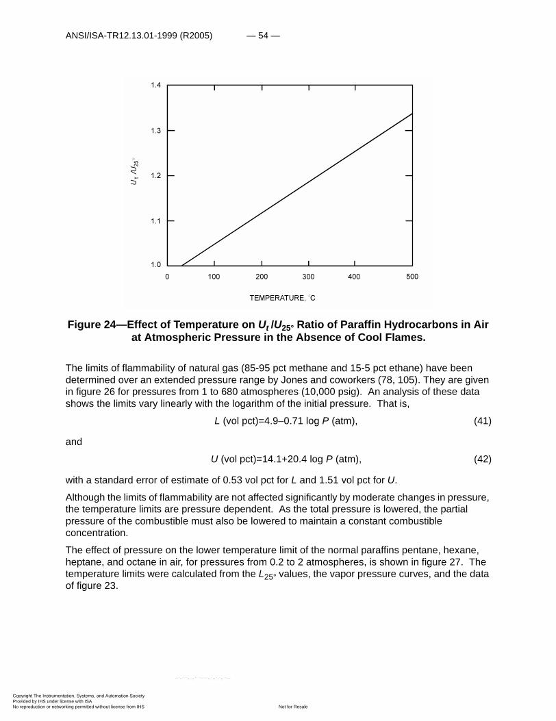
ANSI/ISA-TR12.13.01-1999 (R2005) — 54 —
Copyright The InstrumProvided by IHS underNo reproduction or net
Figure 24—Effect of Temperature on Ut /U25° Ratio of Paraffin Hydrocarbons in Air at Atmospheric Pressure in the Absence of Cool Flames.
The limits of flammability of natural gas (85-95 pct methane and 15-5 pct ethane) have been determined over an extended pressure range by Jones and coworkers (78, 105). They are given in figure 26 for pressures from 1 to 680 atmospheres (10,000 psig). An analysis of these data shows the limits vary linearly with the logarithm of the initial pressure. That is,
L (vol pct)=4.9–0.71 log P (atm), (41)
and
U (vol pct)=14.1+20.4 log P (atm), (42)
with a standard error of estimate of 0.53 vol pct for L and 1.51 vol pct for U.
Although the limits of flammability are not affected significantly by moderate changes in pressure, the temperature limits are pressure dependent. As the total pressure is lowered, the partial pressure of the combustible must also be lowered to maintain a constant combustible concentration.
The effect of pressure on the lower temperature limit of the normal paraffins pentane, hexane, heptane, and octane in air, for pressures from 0.2 to 2 atmospheres, is shown in figure 27. The temperature limits were calculated from the L25° values, the vapor pressure curves, and the data of figure 23.
U/U
1.00 100 200 300 400 500
1.1
1.2
1.3
1.4
TEMPERATURE, C
t25
entation, Systems, and Automation Society license with ISA
Not for Resaleworking permitted without license from IHS
--`,,```,,,,````-`-`,,`,,`,`,,`---
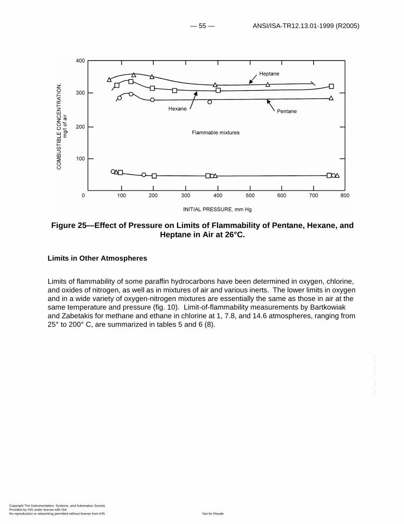
— 55 — ANSI/ISA-TR12.13.01-1999 (R2005)
Copyright The InstrumProvided by IHS underNo reproduction or net
--`,,```,,,,````-`-`,,`,,`,`,,`---
Figure 25—Effect of Pressure on Limits of Flammability of Pentane, Hexane, and Heptane in Air at 26°C.
Limits in Other Atmospheres
Limits of flammability of some paraffin hydrocarbons have been determined in oxygen, chlorine, and oxides of nitrogen, as well as in mixtures of air and various inerts. The lower limits in oxygen and in a wide variety of oxygen-nitrogen mixtures are essentially the same as those in air at the same temperature and pressure (fig. 10). Limit-of-flammability measurements by Bartkowiak and Zabetakis for methane and ethane in chlorine at 1, 7.8, and 14.6 atmospheres, ranging from 25° to 200° C, are summarized in tables 5 and 6 (8).
entation, Systems, and Automation Society license with ISA
Not for Resaleworking permitted without license from IHS
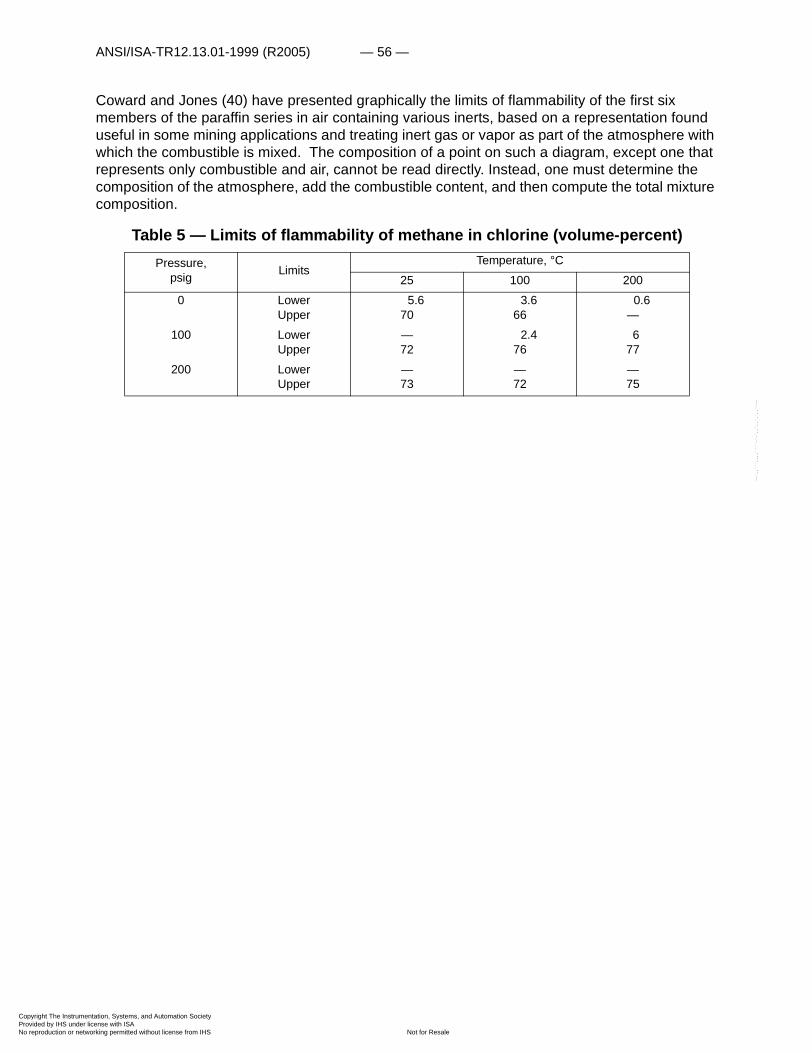
ANSI/ISA-TR12.13.01-1999 (R2005) — 56 —
Copyright The InstrumProvided by IHS underNo reproduction or net
--`,,```,,,,````-`-`,,`,,`,`,,`---
Coward and Jones (40) have presented graphically the limits of flammability of the first six members of the paraffin series in air containing various inerts, based on a representation found useful in some mining applications and treating inert gas or vapor as part of the atmosphere with which the combustible is mixed. The composition of a point on such a diagram, except one that represents only combustible and air, cannot be read directly. Instead, one must determine the composition of the atmosphere, add the combustible content, and then compute the total mixture composition.
Table 5 — Limits of flammability of methane in chlorine (volume-percent)Pressure,
psig LimitsTemperature, °C
25 100 2000 Lower
Upper5.6
703.6
660.6
—100 Lower
Upper—72
2.4 76
677
200 LowerUpper
—73
—72
—75
entation, Systems, and Automation Society license with ISA
Not for Resaleworking permitted without license from IHS
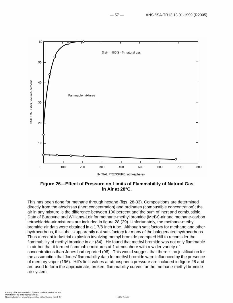
— 57 — ANSI/ISA-TR12.13.01-1999 (R2005)
Copyright The InstrumProvided by IHS underNo reproduction or net
Figure 26—Effect of Pressure on Limits of Flammability of Natural Gas in Air at 28°C.
This has been done for methane through hexane (figs. 28-33). Compositions are determined directly from the abscissas (inert concentration) and ordinates (combustible concentration); the air in any mixture is the difference between 100 percent and the sum of inert and combustible. Data of Burgoyne and Williams-Leir for methane-methyl bromide (MeBr)-air and methane-carbon tetrachloride-air mixtures are included in figure 28 (29). Unfortunately, the methane-methyl bromide-air data were obtained in a 1 7/8-inch tube. Although satisfactory for methane and other hydrocarbons, this tube is apparently not satisfactory for many of the halogenated hydrocarbons. Thus a recent industrial explosion involving methyl bromide prompted Hill to reconsider the flammability of methyl bromide in air (84). He found that methyl bromide was not only flammable in air but that it formed flammable mixtures at 1 atmosphere with a wider variety of concentrations than Jones had reported (96). This would suggest that there is no justification for the assumption that Jones' flammability data for methyl bromide were influenced by the presence of mercury vapor (196). Hill's limit values at atmospheric pressure are included in figure 28 and are used to form the approximate, broken, flammability curves for the methane-methyl bromide-air system.
10
20
30
40
50
60
1000 200 300
NAT
UR
ALG
AS,v
olum
e-pe
rcen
t
Fammable mixtures
%air = 100% - % natural gas
400 500 600 700 800
INITIAL PRESSURE, atmospheres
--`,,```,,,,````-`-`,,`,,`,`,,`---
entation, Systems, and Automation Society license with ISA
Not for Resaleworking permitted without license from IHS
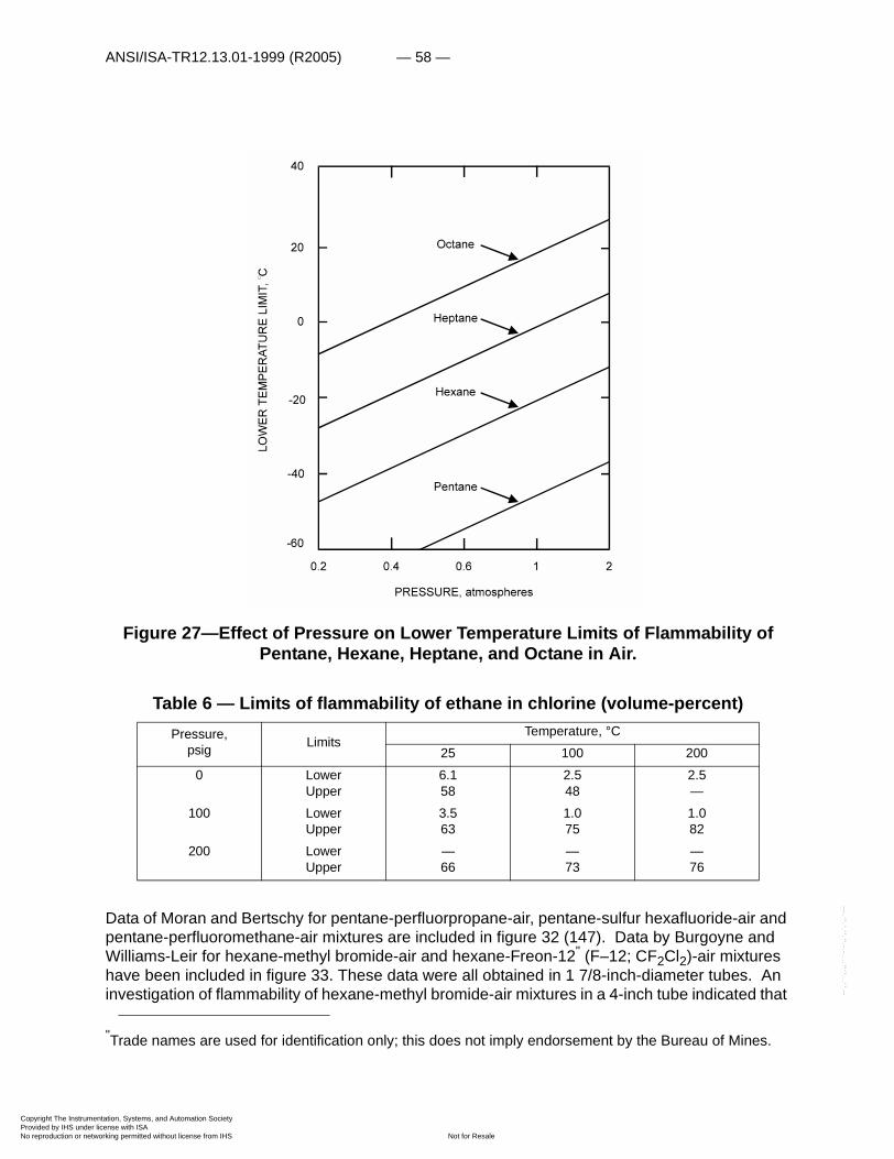
ANSI/ISA-TR12.13.01-1999 (R2005) — 58 —
Copyright The InstrumProvided by IHS underNo reproduction or net
--`,,```,,,,````-`-`,,`,,`,`,,`---
Figure 27—Effect of Pressure on Lower Temperature Limits of Flammability of Pentane, Hexane, Heptane, and Octane in Air.
Table 6 — Limits of flammability of ethane in chlorine (volume-percent)
Data of Moran and Bertschy for pentane-perfluorpropane-air, pentane-sulfur hexafluoride-air and pentane-perfluoromethane-air mixtures are included in figure 32 (147). Data by Burgoyne and Williams-Leir for hexane-methyl bromide-air and hexane-Freon-12" (F–12; CF2Cl2)-air mixtures have been included in figure 33. These data were all obtained in 1 7/8-inch-diameter tubes. An investigation of flammability of hexane-methyl bromide-air mixtures in a 4-inch tube indicated that
Pressure, psig Limits
Temperature, °C25 100 200
0 LowerUpper
6.158
2.548
2.5—
100 LowerUpper
3.563
1.075
1.082
200 LowerUpper
—66
—73
—76
"Trade names are used for identification only; this does not imply endorsement by the Bureau of Mines.
entation, Systems, and Automation Society license with ISA
Not for Resaleworking permitted without license from IHS

— 59 — ANSI/ISA-TR12.13.01-1999 (R2005)
Copyright The InstrumProvided by IHS underNo reproduction or net
--`,,```,,,,````-`-`,,`,,`,`,,`---
an increase in tube size (from 1 7/8-inches to 4-inches-ID) resulted in a narrowing of the flammable range; the upper limit decreased from 7.5 to 5.7 volume-percent n-hexane vapor in air while the lower limit remained constant. The amount of methyl bromide required for extinction decreased from 7.05 volume-percent in the 1 7/8-inch tube to 6.0 volume-percent in the 4-inch tube. However, again this is not in line with the results obtained by Hill with methyl bromide-air mixtures (84). Accordingly, while the data obtained in approximately 2-inch tubes were used to construct figure 33, the Hill data, obtained in a larger apparatus, are also used to form the approximate, broken, flammability curves for the hexane-methyl bromide-air system.
The limits of flammability diagrams for the system n-heptane-water vapor-air at 100° and 200°C (fig. 34) show the effects of temperature on a system that produces both normal and cool flames at atmospheric pressure (192). Interestingly enough, the minimum oxygen requirement for flame propagation (Min O2) at 200°C is the same for the cool and normal flame regions in this instance. Further, the decrease in minimum oxygen requirements (from 13.5±0.3 volume-percent at 100°C to 12.8±0.3 volume-percent at 200°C) is within the range predicted by the modified Burgess-Wheeler law (equation 35 and fig. 23). However, the available data are too meager at present to permit a realistic evaluation of the validity of this law.
entation, Systems, and Automation Society license with ISA
Not for Resaleworking permitted without license from IHS

ANSI/ISA-TR12.13.01-1999 (R2005) — 60 —
Copyright The InstrumProvided by IHS underNo reproduction or net
--`,,```,,,,````-`-`,,`,,`,`,,`---
Figure 28—Limits of Flammability of Various Methane-Inert Gas-Air Mixtures at 25°C and Atmospheric Pressure.
Inspection of the limit-of-flammability curves in figures 28 to 33 reveals that except for methane and ethane, the minimum amounts of carbon dioxide and nitrogen required for flame extinction (peak values) at 25°C and atmospheric pressure are about 28 and 42 volume-percent, respectively. The ratio of these values is approximately inversely proportional to the ratio of their heat capacities at the temperature at which combustion occurs. Accordingly, generalized flammability diagrams of the type given in figure 35 can be constructed for the higher hydrocarbons, ignoring the presence of cool flames. Such diagrams do not appear to be applicable to the halogenated hydrocarbons since these materials tend to decompose even in flames of limit-mixture composition and, as noted, may themselves propagate flame. Coleman
entation, Systems, and Automation Society license with ISA
Not for Resaleworking permitted without license from IHS

— 61 — ANSI/ISA-TR12.13.01-1999 (R2005)
Copyright The InstrumProvided by IHS underNo reproduction or net
--`,,```,,,,````-`-`,,`,,`,`,,`---
(37) has found that the ratios of the peak values of a halogenated hydrocarbon are not constant but are proportional to the heats of combustion of the combustibles to which the halogenated hydrocarbon is added.
Figure 29—Limits of Flammability of Ethane-Carbon Dioxide-Air and Ethane-Nitrogen-Air Mixtures at 25°C and Atmospheric Pressure.
Few data are available for the effects of pressure on the limits of flammability of combustible-inert-air mixtures. One such set of data is summarized in figure 36, which gives the limits of flammability of natural gas (85 pct methane+15 pct ethane) nitrogen-air at 26° C and 0, 500, 1,000 and 2,000 psig (105). Similar data are given for ethane-carbon dioxide-air (fig. 37) and ethane-nitrogen-air (fig. 38) (121), and for propane-carbon dioxide-air (fig. 39) and propane-nitrogen-air (fig. 40) (122). Minimum oxygen requirements for flame propagation (min O2) through natural gas-nitrogen-air, ethane-nitrogen-air, and propane-nitrogen-air at atmospheric
entation, Systems, and Automation Society license with ISA
Not for Resaleworking permitted without license from IHS
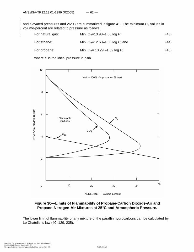
ANSI/ISA-TR12.13.01-1999 (R2005) — 62 —
Copyright The InstrumProvided by IHS underNo reproduction or net
--`,
and elevated pressures and 26° C are summarized in figure 41. The minimum O2 values in volume-percent are related to pressure as follows:
For natural gas: Min. O2=13.98–1.68 log P; (43)
For ethane: Min. O2=12.60–1.36 log P; and (44)
For propane: Min. O2= 13.29 –1.52 log P; (45)
where P is the initial pressure in psia.
Figure 30—Limits of Flammability of Propane-Carbon Dioxide-Air and Propane-Nitrogen-Air Mixtures at 25°C and Atmospheric Pressure.
The lower limit of flammability of any mixture of the paraffin hydrocarbons can be calculated by Le Chatelier's law (40, 129, 235):
,```,,,,````-`-`,,`,,`,`,,`---
entation, Systems, and Automation Society license with ISA
Not for Resaleworking permitted without license from IHS
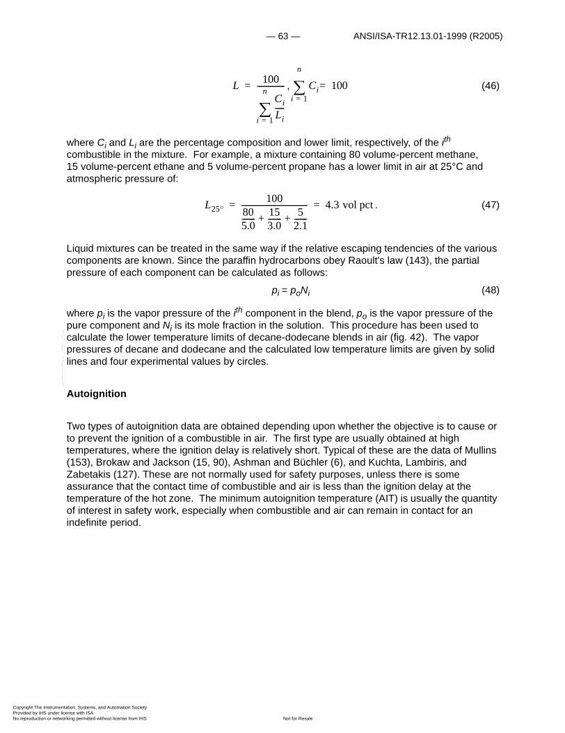
— 63 — ANSI/ISA-TR12.13.01-1999 (R2005)
Copyright The InstrumProvided by IHS underNo reproduction or net
, (46)
where Ci and Li are the percentage composition and lower limit, respectively, of the ith combustible in the mixture. For example, a mixture containing 80 volume-percent methane, 15 volume-percent ethane and 5 volume-percent propane has a lower limit in air at 25°C and atmospheric pressure of:
. (47)
Liquid mixtures can be treated in the same way if the relative escaping tendencies of the various components are known. Since the paraffin hydrocarbons obey Raoult's law (143), the partial pressure of each component can be calculated as follows:
pi = poNi (48)
where pi is the vapor pressure of the ith component in the blend, po is the vapor pressure of the pure component and Ni is its mole fraction in the solution. This procedure has been used to calculate the lower temperature limits of decane-dodecane blends in air (fig. 42). The vapor pressures of decane and dodecane and the calculated low temperature limits are given by solid lines and four experimental values by circles.
Autoignition
Two types of autoignition data are obtained depending upon whether the objective is to cause or to prevent the ignition of a combustible in air. The first type are usually obtained at high temperatures, where the ignition delay is relatively short. Typical of these are the data of Mullins (153), Brokaw and Jackson (15, 90), Ashman and Büchler (6), and Kuchta, Lambiris, and Zabetakis (127). These are not normally used for safety purposes, unless there is some assurance that the contact time of combustible and air is less than the ignition delay at the temperature of the hot zone. The minimum autoignition temperature (AIT) is usually the quantity of interest in safety work, especially when combustible and air can remain in contact for an indefinite period.
L 100
CiLi-----
i 1=
n
�
---------------= Ci 100=i 1=
n
�
L25�100
805.0------- 15
3.0------- 52.1-------+ +
------------------------------------ 4.3 vol pct= =
--`,,```,,,,````-`-`,,`,,`,`,,`---
entation, Systems, and Automation Society license with ISA
Not for Resaleworking permitted without license from IHS
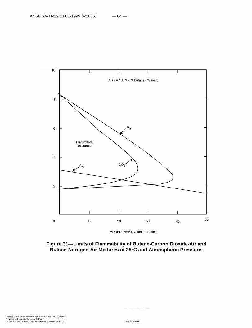
ANSI/ISA-TR12.13.01-1999 (R2005) — 64 —
Copyright The InstrumProvided by IHS underNo reproduction or net
Figure 31—Limits of Flammability of Butane-Carbon Dioxide-Air and Butane-Nitrogen-Air Mixtures at 25°C and Atmospheric Pressure.
entation, Systems, and Automation Society license with ISA
Not for Resaleworking permitted without license from IHS
--`,,```,,,,````-`-`,,`,,`,`,,`---
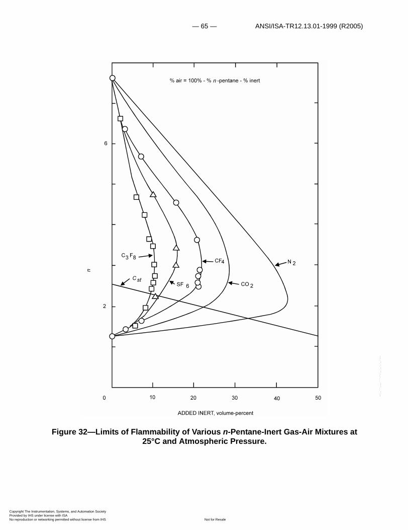
— 65 — ANSI/ISA-TR12.13.01-1999 (R2005)
Copyright The InstrumProvided by IHS underNo reproduction or net
--`,,```,,,,````-`-`,,`,,`,`,,`---
Figure 32—Limits of Flammability of Various n-Pentane-Inert Gas-Air Mixtures at 25°C and Atmospheric Pressure.
entation, Systems, and Automation Society license with ISA
Not for Resaleworking permitted without license from IHS

ANSI/ISA-TR12.13.01-1999 (R2005) — 66 —
Copyright The InstrumProvided by IHS underNo reproduction or net
--`,,```,,,,````-`-`,,`,,`,`,,`---
Figure 33—Limits of Flammability of Various n-Hexane-Inert Gas-Air Mixtures at 25°C and Atmospheric Pressure.
entation, Systems, and Automation Society license with ISA
Not for Resaleworking permitted without license from IHS
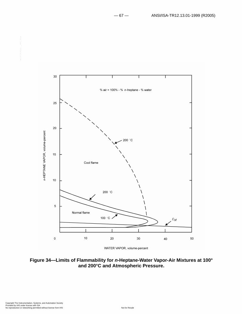
— 67 — ANSI/ISA-TR12.13.01-1999 (R2005)
Copyright The InstrumProvided by IHS underNo reproduction or net
--`,,```,,,,````-`-`,,`,,`,`,,`---
Figure 34—Limits of Flammability for n-Heptane-Water Vapor-Air Mixtures at 100° and 200°C and Atmospheric Pressure.
entation, Systems, and Automation Society license with ISA
Not for Resaleworking permitted without license from IHS
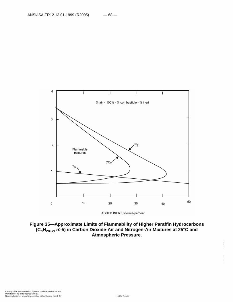
ANSI/ISA-TR12.13.01-1999 (R2005) — 68 —
Copyright The InstrumProvided by IHS underNo reproduction or net
--`,,```,,,,````-`-`,,`,,`,`,,`---
Figure 35—Approximate Limits of Flammability of Higher Paraffin Hydrocarbons (CnH2n+2, n�5) in Carbon Dioxide-Air and Nitrogen-Air Mixtures at 25°C and
Atmospheric Pressure.
entation, Systems, and Automation Society license with ISA
Not for Resaleworking permitted without license from IHS
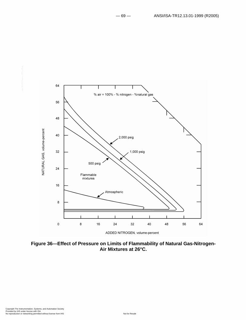
— 69 — ANSI/ISA-TR12.13.01-1999 (R2005)
Copyright The InstrumProvided by IHS underNo reproduction or net
--`,,```,,,,````-`-`,,`,,`,`,,`---
Figure 36—Effect of Pressure on Limits of Flammability of Natural Gas-Nitrogen-Air Mixtures at 26°C.
entation, Systems, and Automation Society license with ISA
Not for Resaleworking permitted without license from IHS
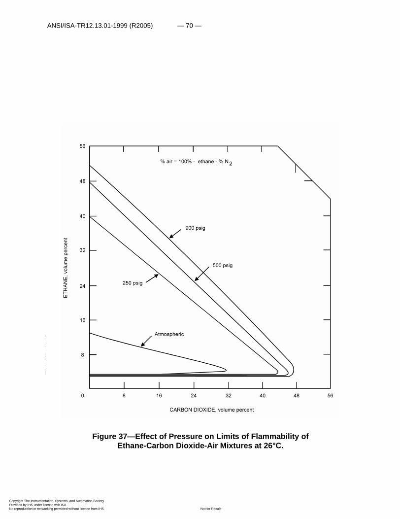
ANSI/ISA-TR12.13.01-1999 (R2005) — 70 —
Copyright The InstrumProvided by IHS underNo reproduction or net
Figure 37—Effect of Pressure on Limits of Flammability of Ethane-Carbon Dioxide-Air Mixtures at 26°C.
--`,,```,,,,````-`-`,,`,,`,`,,`---
entation, Systems, and Automation Society license with ISA
Not for Resaleworking permitted without license from IHS
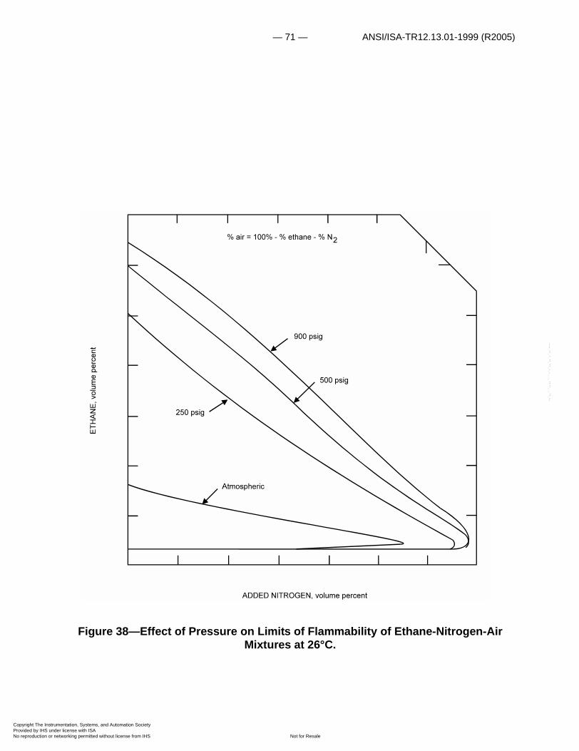
— 71 — ANSI/ISA-TR12.13.01-1999 (R2005)
Copyright The InstrumProvided by IHS underNo reproduction or net
--`,,```,,,,````-`-`,,`,,`,`,,`---
Figure 38—Effect of Pressure on Limits of Flammability of Ethane-Nitrogen-Air Mixtures at 26°C.
entation, Systems, and Automation Society license with ISA
Not for Resaleworking permitted without license from IHS
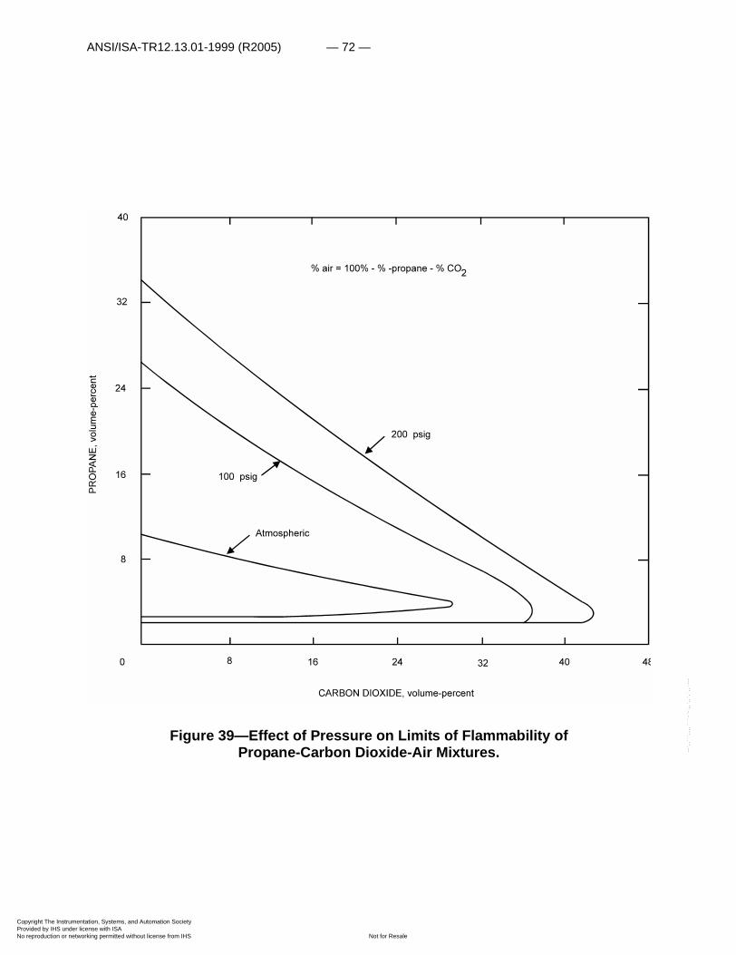
ANSI/ISA-TR12.13.01-1999 (R2005) — 72 —
Copyright The InstrumProvided by IHS underNo reproduction or net
--`,,```,,,,````-`-`,,`,,`,`,,`---
Figure 39—Effect of Pressure on Limits of Flammability of Propane-Carbon Dioxide-Air Mixtures.
entation, Systems, and Automation Society license with ISA
Not for Resaleworking permitted without license from IHS

— 73 — ANSI/ISA-TR12.13.01-1999 (R2005)
Copyright The InstrumProvided by IHS underNo reproduction or net
Figure 40—Effect of Pressure on Limits of Flammability of Propane-Nitrogen-Air Mixtures.
Some AIT values for paraffin hydrocarbons in air obtained by Setchkin in a 1-liter spherical Pyrex flask (194) and by Zabetakis, Furno, and Jones in a 200 cc Pyrex Erlenmeyer flask (237) are given in table 4. Interestingly enough, experiments conducted in these and other flasks generally indicate that flask shape and size are important in determining the AIT. The AIT data obtained in the 200 cc flask may be correlated with molecular structure by plotting them against the average carbon chain length defined as
, (49)Lave
2 giNii
n
�
M M 1– �------------------------=
entation, Systems, and Automation Society license with ISA
Not for Resaleworking permitted without license from IHS
--`,,```,,,,````-`-`,,`,,`,`,,`---

ANSI/ISA-TR12.13.01-1999 (R2005) — 74 —
Copyright The InstrumProvided by IHS underNo reproduction or net
where gi is the number of possible chains each containing Ni carbon atoms and M is the number of methyl (—CH3) groups. For example, n-nonane and 2,2,3,3-tetramethyl pentane each have 9 carbon atoms, but the former has 2 methyl groups and the latter has 6. The former has only one chain of 9 carbon atoms with a methyl group on each end, and the latter has a maximum of 4 chains with 3 carbon atoms, 8 chains with 4 carbon atoms, and 3 chains with 5 carbon atoms. Thus, n-nonane has an average chain length of 9 and 2,2,3,3-tetramethyl pentane has an average of 3.9. The more highly branched a combustible is, the higher its ignition temperature will be. Minimum autoignition temperatures of 20 paraffins were plotted as ordinate against the average chain length as abscissa (fig. 43). The data fall into two regions—a high-temperature region in which the AIT is greater than 400°C and a low temperature region in which the AIT is less than 300°C. These regions coincide with those of Mulcahy who found that oxidation proceeds by one of two different mechanisms (152), and by Frank, Blackham, and Swarts (60). The AIT values of combustibles in the first region are normally much more sensitive to the oxygen concentration of the oxidizing atmosphere and to the spray injection pressure than are the combustibles in the second region. Unfortunately, the available consistent AIT data about the effects of oxygen concentration and injection pressure are too meager to permit a detailed comparison.
The physical processes (206) and reactions that lead to autoignition are of interest in any detailed study of this ignition process. Salooja (184), Terao (207), Affens, Johnson and Carhart (1, 2), and others have studied the autoignition of various hydrocarbons in an effort to determine the mechanisms that lead to the ignition reaction.
An increase in pressure generally decreases the AIT of a combustible in a given oxidant. For example, the AIT of a natural gas in air decreased from 530°C at 1 atmosphere to 240°C at 610 atmospheres (9,000 psig) (78). The AIT's of several hydrocarbons were found to obey Semenov's equation over a limited pressure range (248):
(50)
where T is the AIT at an initial pressure P, and A and B are constants. Accordingly, the AIT values obtained at atmospheric pressure should not be used to assess ignition hazards at high pressures.
PT---
AT--- B+=log
--`,,```,,,,````-`-`,,`,,`,`,,`---
entation, Systems, and Automation Society license with ISA
Not for Resaleworking permitted without license from IHS
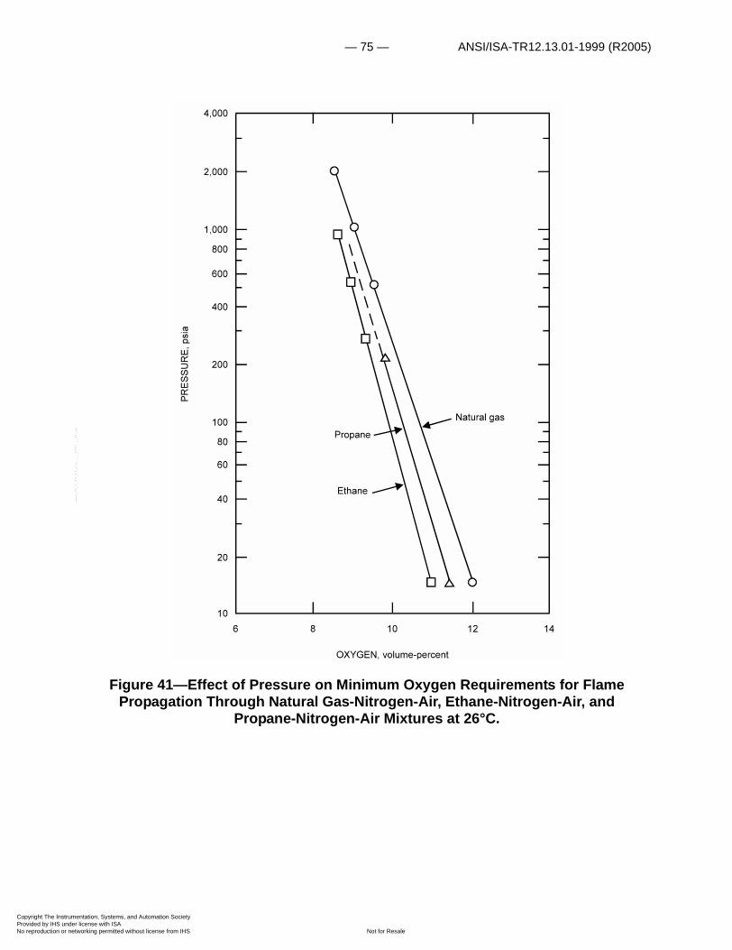
— 75 — ANSI/ISA-TR12.13.01-1999 (R2005)
Copyright The InstrumProvided by IHS underNo reproduction or net
--`,,```,,,,````-`-`,,`,,`,`,,`---
Figure 41—Effect of Pressure on Minimum Oxygen Requirements for Flame Propagation Through Natural Gas-Nitrogen-Air, Ethane-Nitrogen-Air, and
Propane-Nitrogen-Air Mixtures at 26°C.
entation, Systems, and Automation Society license with ISA
Not for Resaleworking permitted without license from IHS
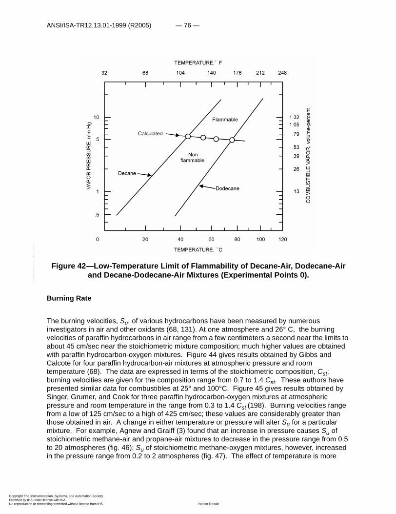
ANSI/ISA-TR12.13.01-1999 (R2005) — 76 —
Copyright The InstrumProvided by IHS underNo reproduction or net
--`,,```,,,,````-`-`,,`,,`,`,,`---
Figure 42—Low-Temperature Limit of Flammability of Decane-Air, Dodecane-Air and Decane-Dodecane-Air Mixtures (Experimental Points 0).
Burning Rate
The burning velocities, Su, of various hydrocarbons have been measured by numerous investigators in air and other oxidants (68, 131). At one atmosphere and 26° C, the burning velocities of paraffin hydrocarbons in air range from a few centimeters a second near the limits to about 45 cm/sec near the stoichiometric mixture composition; much higher values are obtained with paraffin hydrocarbon-oxygen mixtures. Figure 44 gives results obtained by Gibbs and Calcote for four paraffin hydrocarbon-air mixtures at atmospheric pressure and room temperature (68). The data are expressed in terms of the stoichiometric composition, Cst; burning velocities are given for the composition range from 0.7 to 1.4 Cst. These authors have presented similar data for combustibles at 25° and 100°C. Figure 45 gives results obtained by Singer, Grumer, and Cook for three paraffin hydrocarbon-oxygen mixtures at atmospheric pressure and room temperature in the range from 0.3 to 1.4 Cst (198). Burning velocities range from a low of 125 cm/sec to a high of 425 cm/sec; these values are considerably greater than those obtained in air. A change in either temperature or pressure will alter Su for a particular mixture. For example, Agnew and Graiff (3) found that an increase in pressure causes Su of stoichiometric methane-air and propane-air mixtures to decrease in the pressure range from 0.5 to 20 atmospheres (fig. 46); Su of stoichiometric methane-oxygen mixtures, however, increased in the pressure range from 0.2 to 2 atmospheres (fig. 47). The effect of temperature is more
entation, Systems, and Automation Society license with ISA
Not for Resaleworking permitted without license from IHS

— 77 — ANSI/ISA-TR12.13.01-1999 (R2005)
Copyright The InstrumProvided by IHS underNo reproduction or net
,,`,,`,`,,`---
consistent. For a given pressure and mixture composition, an increase in temperature raises Su. In general:
Su = A + BTn (51)
where A and B are constants, T is the temperature and n is a constant for a particular mixture composition. Dugger, Heimel, and Weast (50, 51, 81) obtained a value of 2.0 for n for some of the paraffin hydrocarbons (fig. 48). The burning velocity of the stoichiometric methane-air and methane-oxygen mixtures given in figures 44 and 45 do not agree with the values given in figures 46 to 48 but, in each case, the burning velocity data are internally consistent.
Figure 43—Minimum Autoignition Temperatures of Paraffin Hydrocarbons in Air as a Function of Average Carbon Chain Length.
550
500
450
400
350n-
300
250
200
1 3 5 7 9 11 13 15 17
C
CC
C
CC
C
C
CC-C-C-C-C
C-C-C-C
C-C-C-C
C-C-CC-C-C
C C
C CC-C-C-C-C
CC
CC
C-C-C-C-C
CH
C H
C H
C H
n- C H
n- C H
n- C H
n- C H
n- C H
4
2 6
3 8
4 10
5 12
6 14
7 16
8 18
9 20 n- C H10 22
n- C H16 34
n- C H14 30
n- C H12 26
L avgAVERAGE CARBON CHAIN LENGTH,
entation, Systems, and Automation Society license with ISA
Not for Resaleworking permitted without license from IHS
--`,,```,,,,````-`-`
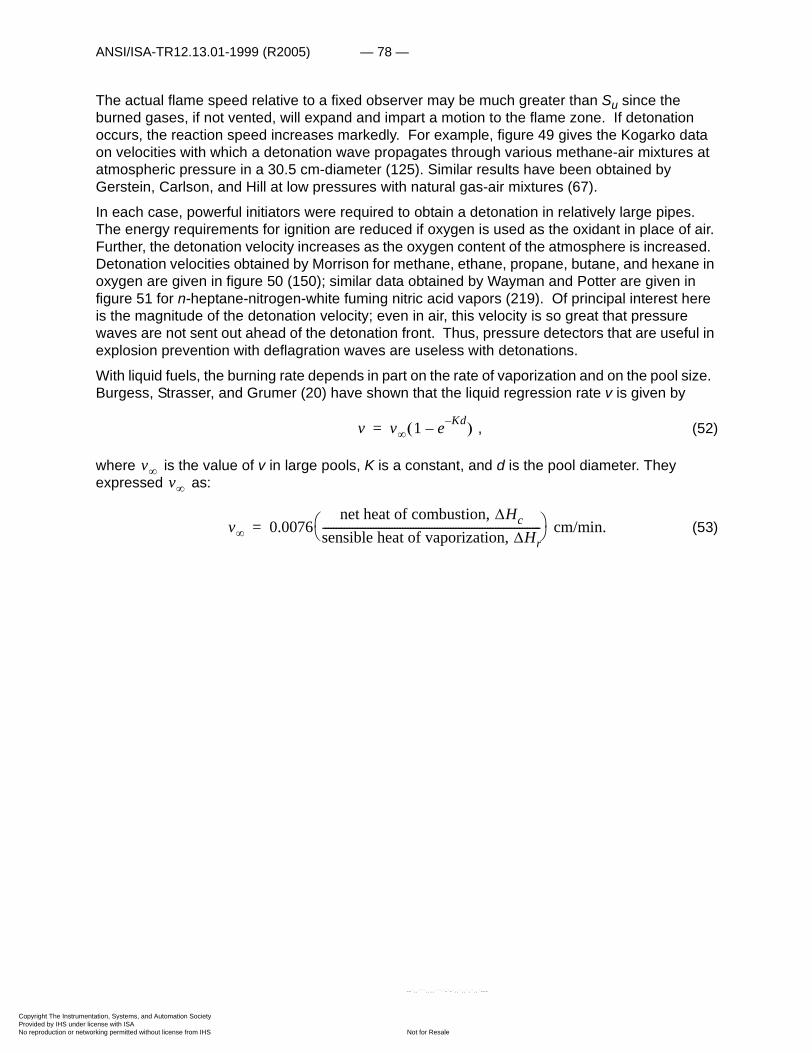
ANSI/ISA-TR12.13.01-1999 (R2005) — 78 —
Copyright The InstrumProvided by IHS underNo reproduction or net
The actual flame speed relative to a fixed observer may be much greater than Su since the burned gases, if not vented, will expand and impart a motion to the flame zone. If detonation occurs, the reaction speed increases markedly. For example, figure 49 gives the Kogarko data on velocities with which a detonation wave propagates through various methane-air mixtures at atmospheric pressure in a 30.5 cm-diameter (125). Similar results have been obtained by Gerstein, Carlson, and Hill at low pressures with natural gas-air mixtures (67).
In each case, powerful initiators were required to obtain a detonation in relatively large pipes. The energy requirements for ignition are reduced if oxygen is used as the oxidant in place of air. Further, the detonation velocity increases as the oxygen content of the atmosphere is increased. Detonation velocities obtained by Morrison for methane, ethane, propane, butane, and hexane in oxygen are given in figure 50 (150); similar data obtained by Wayman and Potter are given in figure 51 for n-heptane-nitrogen-white fuming nitric acid vapors (219). Of principal interest here is the magnitude of the detonation velocity; even in air, this velocity is so great that pressure waves are not sent out ahead of the detonation front. Thus, pressure detectors that are useful in explosion prevention with deflagration waves are useless with detonations.
With liquid fuels, the burning rate depends in part on the rate of vaporization and on the pool size. Burgess, Strasser, and Grumer (20) have shown that the liquid regression rate v is given by
, (52)
where is the value of v in large pools, K is a constant, and d is the pool diameter. They expressed as:
(53)
v v� 1 e Kd–– �=
v�v�
v� 0.0076net heat of combustion, �Hc
sensible heat of vaporization, �Hr----------------------------------------------------------------------------------� �� � cm/min.=
entation, Systems, and Automation Society license with ISA
Not for Resaleworking permitted without license from IHS
--`,,```,,,,````-`-`,,`,,`,`,,`---

— 79 — ANSI/ISA-TR12.13.01-1999 (R2005)
Copyright The InstrumProvided by IHS underNo reproduction or net
--`,,```,,,,````-`-`,,`,,`,`,,`---
Figure 44—Burning Velocities of Methane-, Ethane-, Propane-, and n-Heptane Vapor-Air Mixtures at Atmospheric Pressure and Room Temperature.
entation, Systems, and Automation Society license with ISA
Not for Resaleworking permitted without license from IHS

ANSI/ISA-TR12.13.01-1999 (R2005) — 80 —
Copyright The InstrumProvided by IHS underNo reproduction or net
Figure 45—Burning Velocities of Methane-, Ethane-, and Propane-Oxygen, Mixtures at Atmospheric Pressure and Room Temperature.
entation, Systems, and Automation Society license with ISA
Not for Resaleworking permitted without license from IHS
--`,,```,,,,````-`-`,,`,,`,`,,`---
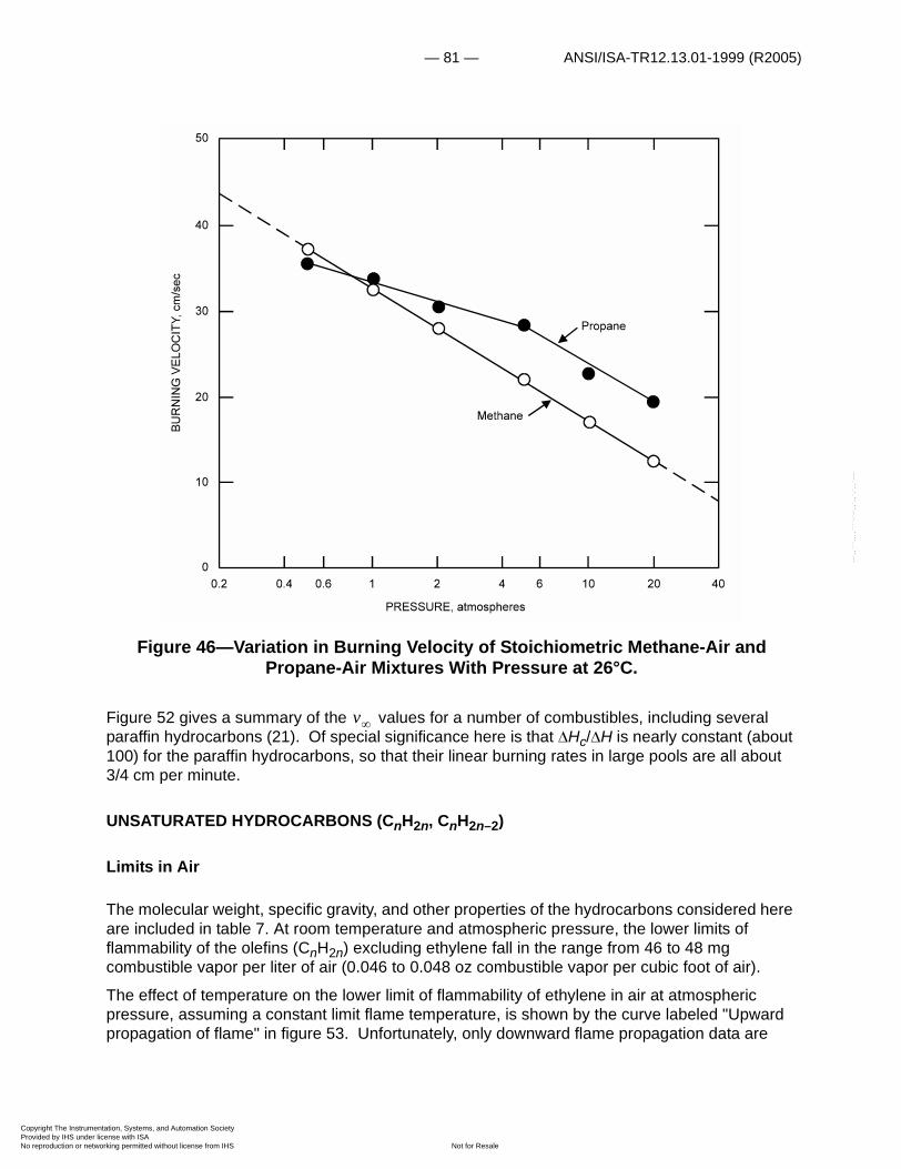
— 81 — ANSI/ISA-TR12.13.01-1999 (R2005)
Copyright The InstrumProvided by IHS underNo reproduction or net
--`,,```,,,,````-`-`,,`,,`,`,,`---
Figure 46—Variation in Burning Velocity of Stoichiometric Methane-Air and Propane-Air Mixtures With Pressure at 26°C.
Figure 52 gives a summary of the values for a number of combustibles, including several paraffin hydrocarbons (21). Of special significance here is that �Hc/�H is nearly constant (about 100) for the paraffin hydrocarbons, so that their linear burning rates in large pools are all about3/4 cm per minute.
UNSATURATED HYDROCARBONS (CnH2n, CnH2n–2)
Limits in Air
The molecular weight, specific gravity, and other properties of the hydrocarbons considered here are included in table 7. At room temperature and atmospheric pressure, the lower limits of flammability of the olefins (CnH2n) excluding ethylene fall in the range from 46 to 48 mg combustible vapor per liter of air (0.046 to 0.048 oz combustible vapor per cubic foot of air).
The effect of temperature on the lower limit of flammability of ethylene in air at atmospheric pressure, assuming a constant limit flame temperature, is shown by the curve labeled "Upward propagation of flame" in figure 53. Unfortunately, only downward flame propagation data are
v�
entation, Systems, and Automation Society license with ISA
Not for Resaleworking permitted without license from IHS

ANSI/ISA-TR12.13.01-1999 (R2005) — 82 —
Copyright The InstrumProvided by IHS underNo reproduction or net
,,,````-`-`,,`,,`,`,,`---
available over an extended temperature range (222); these are included in figure 53. As in the case of similar data obtained with methane, these define a straight line parallel to the "Constant flame temperature," "Upward propagation of flame" line. Again, the modified Burgess-Wheeler law, equation (33), gives a variation in lower limit with temperature that is close to that given by the "Constant flame temperature" line, so that either could be used at temperatures below the AIT of ethylene (490°C). Moreover, as the limit flame temperatures of olefins are not too different from those of paraffin hydrocarbons, the generalized graph for Lt /L25° (fig. 23) can be used for these unsaturated hydrocarbons.
Table 7 — Properties of unsaturated hydrocarbons
1 Figures compiled at Explosive Res. Center, Federal Bureau of Mines.2 Calculated value.
Combustible Formula M Sp gr (Air=1)
Cst in air (vol pct)
Net�Hc
Lower limit in air Upper limit in air
L25 (vol pct)
Ref. U25 (vol pct)
Ref.
Ethylene C2H4 28.05 0.97 6.53 316.2 2.7 0.41 35 (115) 36 5.5 700 (26)
Propylene C3H6 42.08 1.45 4.45 460.4 2.4 .54 46 (101) 11 2.5 210 (40)
Butene-1 C4H8 56.10 1.94 3.37 607.7 1.7 .50 44 (1) 9.7 2.9 270 (1)
cis-Butene-2 C4H8 56.10 1.94 3.37 606.0 1.8 .53 46 (40) 9.7 2.9 270 (40)
Isobutylene C4H8 56.10 1.94 3.37 604.1 1.8 .53 46 (40) 9.6 2.8 260 (26)
3-Methyl-butene-1 C5H10 70.13 2.42 2.72 752.3 1.5 .55 48 (40) 9.1 3.3 310 (40)
Propadiene C3H4 40.06 1.38 4.97 443.7 2.6 .53 48 (2) — — — —
1,3-Butadiene C4H6 54.09 1.87 3.67 576.3 2.0 .54 49 (102) 12 3.3 320 (26)
Kcalmole------------� �� �
L25Cst---------
L mg1-------� �
� � U25Cst----------
U mg1-------� �
� �
entation, Systems, and Automation Society license with ISA
Not for Resaleworking permitted without license from IHS
--`,,```,

— 83 — ANSI/ISA-TR12.13.01-1999 (R2005)
Copyright The InstrumProvided by IHS underNo reproduction or net
--`,,```,,,,````-`-`,,`,,`,`,,`---
Figure 47—Variation in Burning Velocity of Stoichiometric Methane- and Ethylene-Oxygen Mixtures With Pressure at 26°C.
entation, Systems, and Automation Society license with ISA
Not for Resaleworking permitted without license from IHS
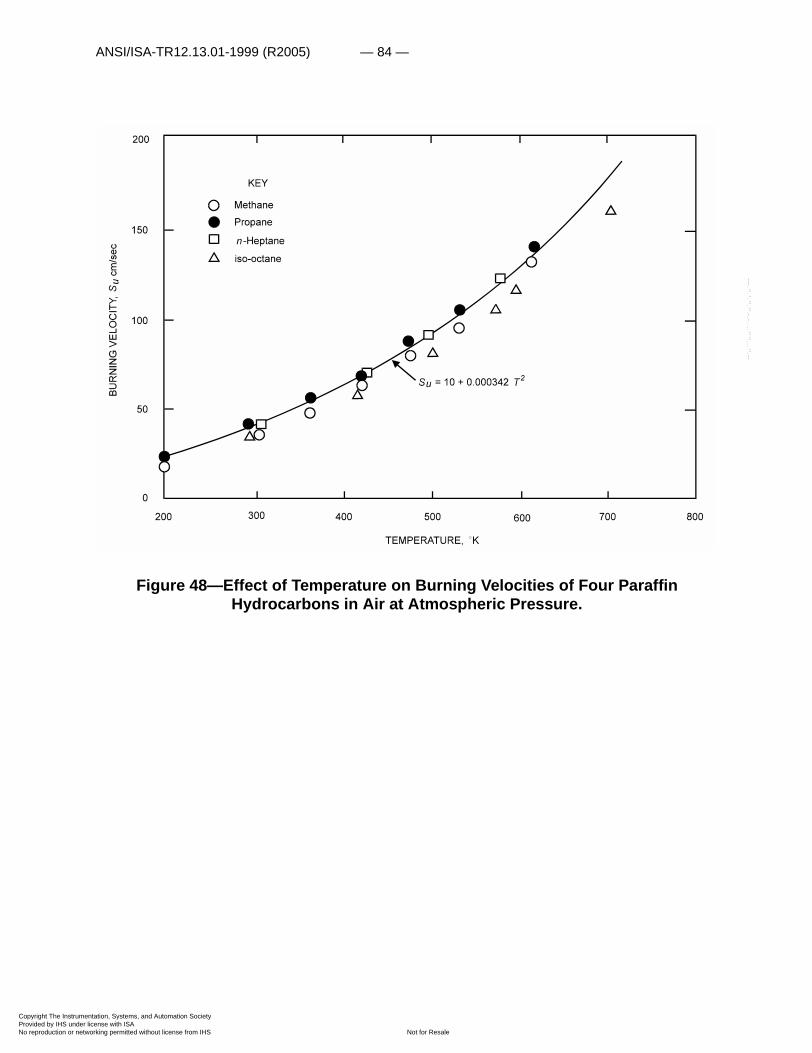
ANSI/ISA-TR12.13.01-1999 (R2005) — 84 —
Copyright The InstrumProvided by IHS underNo reproduction or net
--`,,```,,,,````-`-`,,`,,`,`,,`---
Figure 48—Effect of Temperature on Burning Velocities of Four Paraffin Hydrocarbons in Air at Atmospheric Pressure.
entation, Systems, and Automation Society license with ISA
Not for Resaleworking permitted without license from IHS

— 85 — ANSI/ISA-TR12.13.01-1999 (R2005)
Copyright The InstrumProvided by IHS underNo reproduction or net
Figure 49—Detonation Velocities of Methane-Air Mixtures at Atmospheric Pressure. (Initiator: 50-70 grams of amatol explosive. Pipe diameter: 30.5 cm.)
--`,,```,,,,````-`-`,,`,,`,`,,`---
entation, Systems, and Automation Society license with ISA
Not for Resaleworking permitted without license from IHS
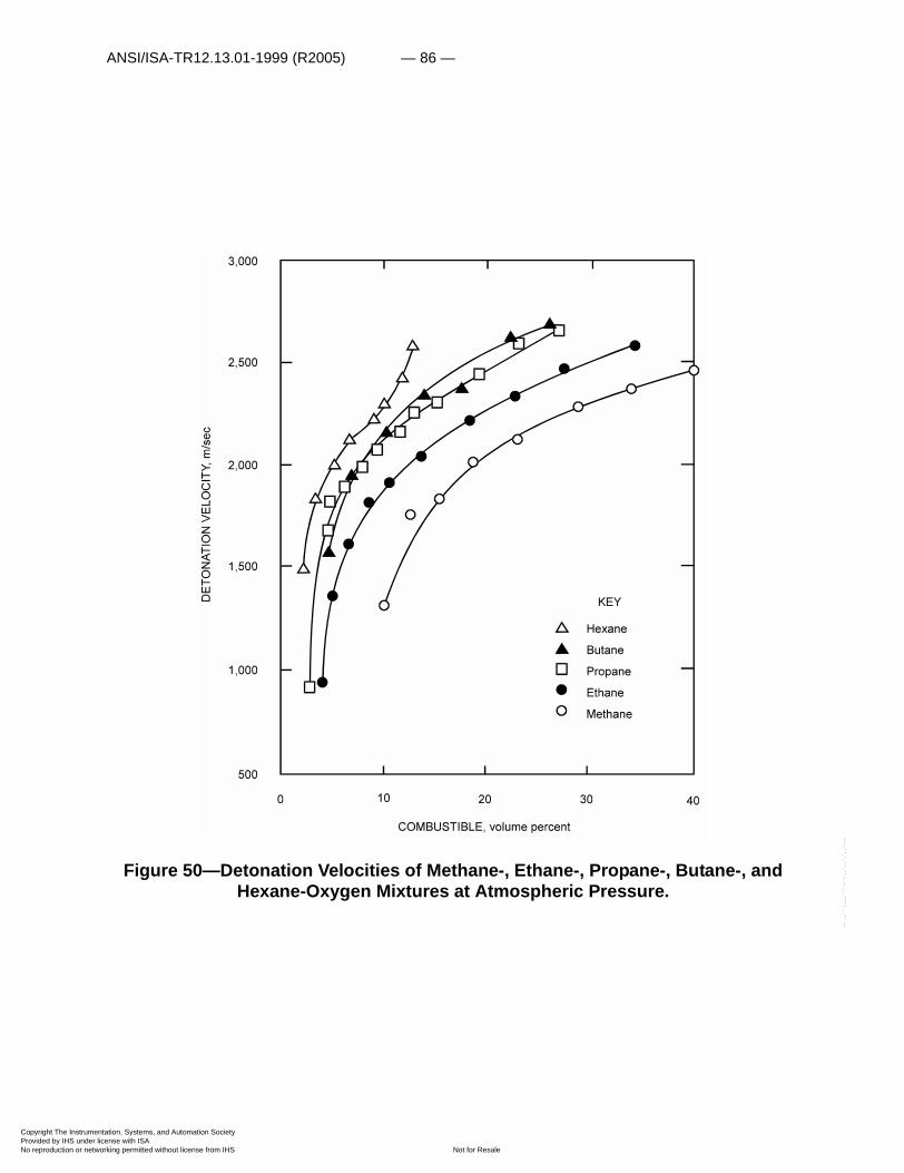
ANSI/ISA-TR12.13.01-1999 (R2005) — 86 —
Copyright The InstrumProvided by IHS underNo reproduction or net
--`,,```,,,,````-`-`,,`,,`,`,,`---
Figure 50—Detonation Velocities of Methane-, Ethane-, Propane-, Butane-, and Hexane-Oxygen Mixtures at Atmospheric Pressure.
entation, Systems, and Automation Society license with ISA
Not for Resaleworking permitted without license from IHS

— 87 — ANSI/ISA-TR12.13.01-1999 (R2005)
Copyright The InstrumProvided by IHS underNo reproduction or net
--`,,```,,,,````-`-`,,`,,`,`,,`---
Figure 51—Detonation Velocities of n-Heptane Vapor in WFNA (White Fuming Nitric Acid)-Nitrogen Gas Mixtures at Atmospheric Pressure and 400°K.
entation, Systems, and Automation Society license with ISA
Not for Resaleworking permitted without license from IHS
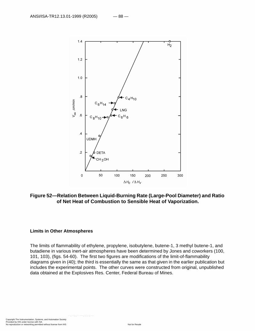
ANSI/ISA-TR12.13.01-1999 (R2005) — 88 —
Copyright The InstrumProvided by IHS underNo reproduction or net
Figure 52—Relation Between Liquid-Burning Rate (Large-Pool Diameter) and Ratio of Net Heat of Combustion to Sensible Heat of Vaporization.
Limits in Other Atmospheres
The limits of flammability of ethylene, propylene, isobutylene, butene-1, 3 methyl butene-1, and butadiene in various inert-air atmospheres have been determined by Jones and coworkers (100, 101, 103), (figs. 54-60). The first two figures are modifications of the limit-of-flammability diagrams given in (40); the third is essentially the same as that given in the earlier publication but includes the experimental points. The other curves were constructed from original, unpublished data obtained at the Explosives Res. Center, Federal Bureau of Mines.
entation, Systems, and Automation Society license with ISA
Not for Resaleworking permitted without license from IHS
--`,,```,,,,````-`-`,,`,,`,`,,`---
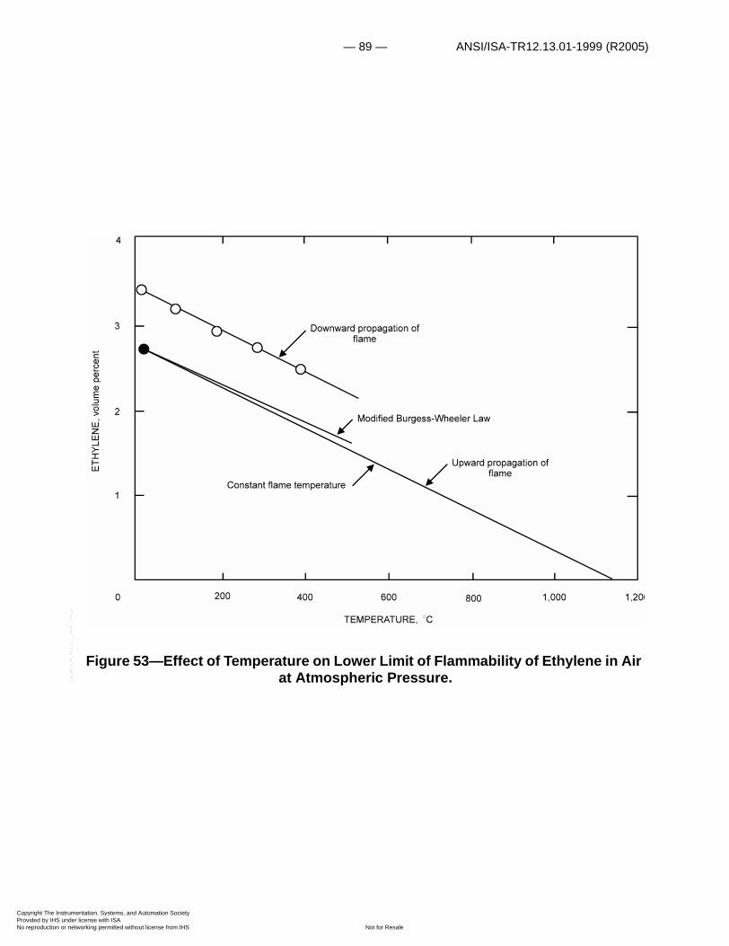
— 89 — ANSI/ISA-TR12.13.01-1999 (R2005)
Copyright The InstrumProvided by IHS underNo reproduction or net
--`,,```,,,,````-`-`,,`,,`,`,,`---
Figure 53—Effect of Temperature on Lower Limit of Flammability of Ethylene in Air at Atmospheric Pressure.
entation, Systems, and Automation Society license with ISA
Not for Resaleworking permitted without license from IHS
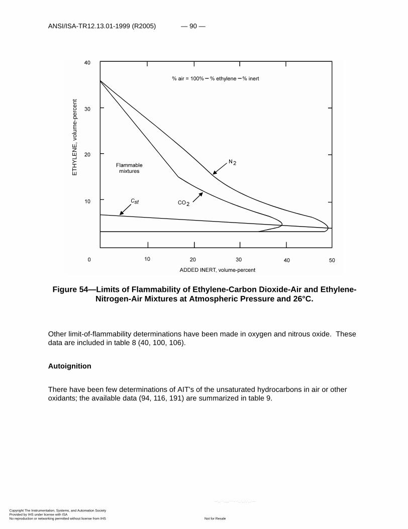
ANSI/ISA-TR12.13.01-1999 (R2005) — 90 —
Copyright The InstrumProvided by IHS underNo reproduction or net
Figure 54—Limits of Flammability of Ethylene-Carbon Dioxide-Air and Ethylene-Nitrogen-Air Mixtures at Atmospheric Pressure and 26°C.
Other limit-of-flammability determinations have been made in oxygen and nitrous oxide. These data are included in table 8 (40, 100, 106).
Autoignition
There have been few determinations of AIT's of the unsaturated hydrocarbons in air or other oxidants; the available data (94, 116, 191) are summarized in table 9.
ETH
YLEN
E, v
olum
e-pe
rcen
t
entation, Systems, and Automation Society license with ISA
Not for Resaleworking permitted without license from IHS
--`,,```,,,,````-`-`,,`,,`,`,,`---

— 91 — ANSI/ISA-TR12.13.01-1999 (R2005)
Copyright The InstrumProvided by IHS underNo reproduction or net
Figure 55—Limits of Flammability of Propylene-Carbon Dioxide-Air and Propylene-Nitrogen-Air Mixtures at Atmospheric Pressure and 26°C.
entation, Systems, and Automation Society license with ISA
Not for Resaleworking permitted without license from IHS
--`,,```,,,,````-`-`,,`,,`,`,,`---

ANSI/ISA-TR12.13.01-1999 (R2005) — 92 —
Copyright The InstrumProvided by IHS underNo reproduction or net
--`,,```,,,,````-`-`,,`,,`,`,,`---
Burning Rate
The burning velocity of ethylene has been determined in air, oxygen, and oxygen-nitrogen atmospheres by numerous investigators (3, 47, 49, 68, 131). In general, it is higher than the velocities of the paraffin hydrocarbons under the same conditions (fig. 47). Similar results are to be expected for other unsaturated hydrocarbons, although the available data are rather meager.
Stability
Many unsaturated hydrocarbon vapors can propagate flame in the absence of air at elevated temperatures and pressures; that is, they have no upper limit of flammability. These combustibles have positive heats of formation,��Hf (table 10) and would therefore liberate heat if decomposed to the elements carbon and hydrogen. Even more heat would be liberated if gases with a negative heat of formation—for example, methane—form from the elements. In practice, a mixture of products results upon decomposition of such combustibles. For example, a propagating decomposition reaction can be initiated in pure ethylene in a 2-inch-ID tube at 23°C and pressures as low as 750 psig, using 2 grams of guncotton. A reaction can be initiated at 21°C and pressures as low as 975 psig with 1 gram of guncotton. The decomposition products are primarily carbon, methane, and hydrogen; approximately 30 Kcal are released per mole of ethylene decomposed. Propylene yielded similar products following explosive decomposition during compression to 4,860 atmospheres (34).
Propadiene and butadiene also decompose readily under the action of powerful ignitors. Propadiene vapor has been decomposed in a 2-inch tube at 120°C and 50 psig using a platinum wire ignitor. Decomposition of butadiene in an industrial accident resulted in a "popcorn" polymer; the reaction was apparently initiated by an unstable peroxide (4).
ACETYLENIC HYDROCARBONS (CnH2n–2)
Limits in Air
Acetylene forms flammable mixtures in air at atmospheric pressure and 25°C, in a range from 2.5 to 100 volume-percent acetylene. Quenched and apparatus limited upper limits have been obtained in 1- , and 2-, and 3-inch diameter tubes (40), but pure acetylene can propagate flame at atmospheric pressure in tubes with diameters of at least 5 inches. Sargent has summarized available data on initial pressure requirements for deflagration and detonation through acetylene in horizontal tubes of about .02 to 6 inches ID at 60°F. (89, 185). His curves are given in figure 61, which also includes an experimental point from the data of Jones and coworkers obtained in a vertical 2-inch-diameter tube. The existence of this point, at a pressure below that given by Sargent's curve for a 2-inch tube, indicates that this curve should be used only for horizontal systems. The point labeled "Industrial explosion" was reported by Miller and Penny (144) and presumably refers to a deflagration. The third experimental point is discussed, along with the detonation curve, in the section on stability.
entation, Systems, and Automation Society license with ISA
Not for Resaleworking permitted without license from IHS

— 93 — ANSI/ISA-TR12.13.01-1999 (R2005)
Copyright The InstrumProvided by IHS underNo reproduction or net
--`,,```,,,,````-`-`,,`,,`,`,,`---
Figure 56—Limits of Flammability of Isobutylene-Carbon Dioxide-Air and Isobutylene-Nitrogen-Air Mixtures at Atmospheric Pressure and 26°C.
entation, Systems, and Automation Society license with ISA
Not for Resaleworking permitted without license from IHS
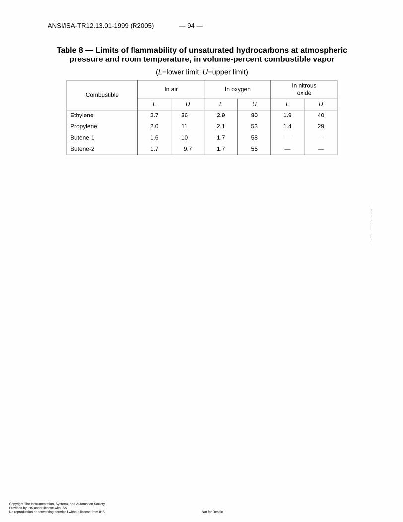
ANSI/ISA-TR12.13.01-1999 (R2005) — 94 —
Copyright The InstrumProvided by IHS underNo reproduction or net
--`,,```,,,,````-`-`,,`,,`,`,,`---
Table 8 — Limits of flammability of unsaturated hydrocarbons at atmospheric pressure and room temperature, in volume-percent combustible vapor
(L=lower limit; U=upper limit)
CombustibleIn air In oxygen In nitrous
oxide
L U L U L U
Ethylene 2.7 36 2.9 80 1.9 40
Propylene 2.0 11 2.1 53 1.4 29
Butene-1 1.6 10 1.7 58 — —
Butene-2 1.7 9.7 1.7 55 — —
entation, Systems, and Automation Society license with ISA
Not for Resaleworking permitted without license from IHS

— 95 — ANSI/ISA-TR12.13.01-1999 (R2005)
Copyright The InstrumProvided by IHS underNo reproduction or net
--`,,```,,,,````-`-`,,`,,`,`,,`---
Table 9 — Minimum autoignition temperatures of unsaturated hydrocarbons at atmospheric pressure
(1)Figures compiled by Explosives Res. Center, Federal Bureau of Mines.
Table 10 — Heats of formation (Kcal/mole) of unsaturated hydrocarbons at 25°C.
1Refs. (124,183).
Autoignition Temperature
CombustibleIn air In oxygen
°C °F Ref. °C °F Ref.
Ethylene 490 914 (116) 485 905 (116)
Propylene 458 856 (94) 423 793 (1)
Butene-1 384 723 (1) 310 590 (1)
Butene-2 324 615 (1) — — —
1,3-Butadiene 418 784 (191) 335 635 (191)
Combustible: �Hf1
Acetylene 54.2
Propadiene 45. 9
Methylacetylene 44.3
1-3, Butadiene 26.8
Ethylene 12.5
Propylene 4.9
1-Butene .3
entation, Systems, and Automation Society license with ISA
Not for Resaleworking permitted without license from IHS
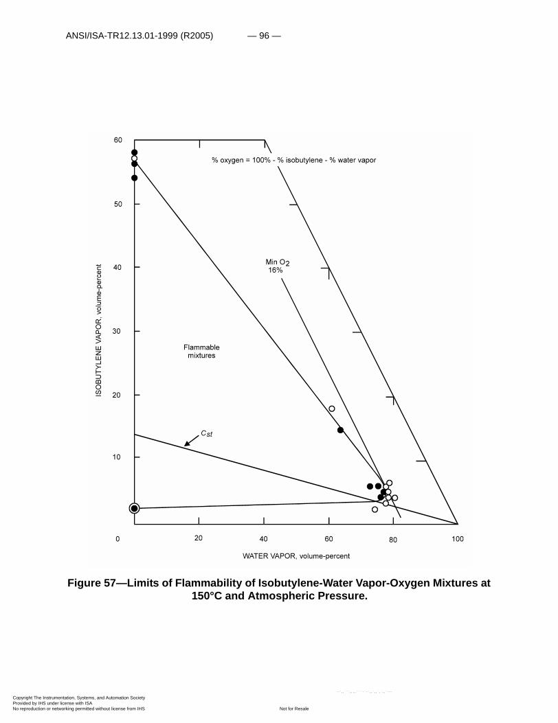
ANSI/ISA-TR12.13.01-1999 (R2005) — 96 —
Copyright The InstrumProvided by IHS underNo reproduction or net
Figure 57—Limits of Flammability of Isobutylene-Water Vapor-Oxygen Mixtures at 150°C and Atmospheric Pressure.
entation, Systems, and Automation Society license with ISA
Not for Resaleworking permitted without license from IHS
--`,,```,,,,````-`-`,,`,,`,`,,`---
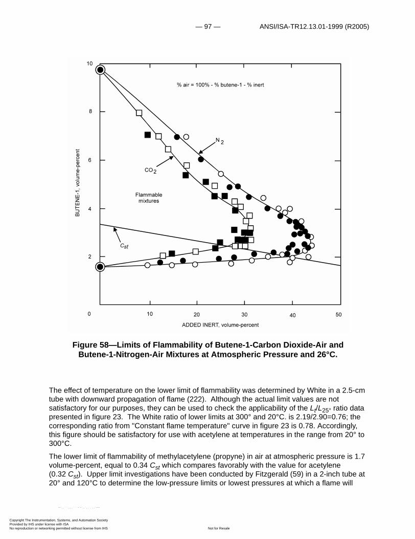
— 97 — ANSI/ISA-TR12.13.01-1999 (R2005)
Copyright The InstrumProvided by IHS underNo reproduction or net
Figure 58—Limits of Flammability of Butene-1-Carbon Dioxide-Air and Butene-1-Nitrogen-Air Mixtures at Atmospheric Pressure and 26°C.
The effect of temperature on the lower limit of flammability was determined by White in a 2.5-cm tube with downward propagation of flame (222). Although the actual limit values are not satisfactory for our purposes, they can be used to check the applicability of the Lt/L25° ratio data presented in figure 23. The White ratio of lower limits at 300° and 20°C. is 2.19/2.90=0.76; the corresponding ratio from "Constant flame temperature" curve in figure 23 is 0.78. Accordingly, this figure should be satisfactory for use with acetylene at temperatures in the range from 20° to 300°C.
The lower limit of flammability of methylacetylene (propyne) in air at atmospheric pressure is 1.7 volume-percent, equal to 0.34 Cst which compares favorably with the value for acetylene (0.32 Cst). Upper limit investigations have been conducted by Fitzgerald (59) in a 2-inch tube at 20° and 120°C to determine the low-pressure limits or lowest pressures at which a flame will
entation, Systems, and Automation Society license with ISA
Not for Resaleworking permitted without license from IHS
--`,,```,,,,````-`-`,,`,,`,`,,`---

ANSI/ISA-TR12.13.01-1999 (R2005) — 98 —
Copyright The InstrumProvided by IHS underNo reproduction or net
--`,,```,,,,````-`-`,,`,,`,`,,`---
propagate through methylacetylene vapor at these temperatures. He found these to be 50 and 30 psig at 20° and 120°C, respectively. In a 4-inch tube, Hall and Straker (77) obtained a low-pressure limit of 43 psig at 20°C. This indicates that the upper limit of flammability of methylacetylene in air is probably less than 100 percent at 20°C and 1 atmosphere.
The quantities of propylene required to prevent flame propagation through methyl-acetylene-propadiene-propylene mixtures at 120°C and 50 and 100 psig have been determined in 1-, 2-, 4-, and 12-inch tubes (fig. 62), and at 120°C and 100 psig in a 24-inch sphere. As noted, the propylene requirements are strongly affected by temperature, pressure, and container size. As the tube diameter increases, the quantity of propylene required to prevent flame propagation increases; this effect is less pronounced in the larger vessels (diameter greater than 4 inches) than in the smaller vessels (diameter less than 4 inches). The results obtained in the 24-inch sphere were similar to those in the 12-inch tube.
Figure 59: Limits of Flammability of 3 Methyl Butene-1-Carbon Dioxide-Air and 3 Methyl-Butene-1-Nitrogen-Air Mixtures at Atmospheric Pressure and 26°C.
entation, Systems, and Automation Society license with ISA
Not for Resaleworking permitted without license from IHS
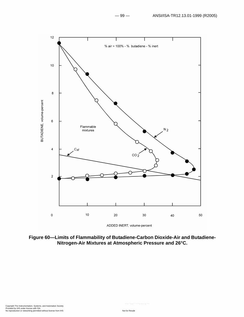
— 99 — ANSI/ISA-TR12.13.01-1999 (R2005)
Copyright The InstrumProvided by IHS underNo reproduction or net
Figure 60—Limits of Flammability of Butadiene-Carbon Dioxide-Air and Butadiene-Nitrogen-Air Mixtures at Atmospheric Pressure and 26°C.
entation, Systems, and Automation Society license with ISA
Not for Resaleworking permitted without license from IHS
--`,,```,,,,````-`-`,,`,,`,`,,`---
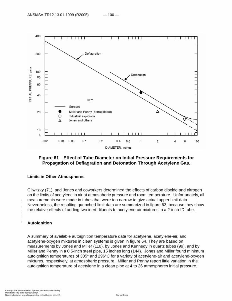
ANSI/ISA-TR12.13.01-1999 (R2005) — 100 —
Copyright The InstrumProvided by IHS underNo reproduction or net
--`,,```,,,,````-`-`,,`,,`,`,,`---
Figure 61—Effect of Tube Diameter on Initial Pressure Requirements for Propagation of Deflagration and Detonation Through Acetylene Gas.
Limits in Other Atmospheres
Gliwitzky (71), and Jones and coworkers determined the effects of carbon dioxide and nitrogen on the limits of acetylene in air at atmospheric pressure and room temperature. Unfortunately, all measurements were made in tubes that were too narrow to give actual upper limit data. Nevertheless, the resulting quenched-limit data are summarized in figure 63, because they show the relative effects of adding two inert diluents to acetylene-air mixtures in a 2-inch-ID tube.
Autoignition
A summary of available autoignition temperature data for acetylene, acetylene-air, and acetylene-oxygen mixtures in clean systems is given in figure 64. They are based on measurements by Jones and Miller (110), by Jones and Kennedy in quartz tubes (99), and by Miller and Penny in a 0.5-inch steel pipe, 15 inches long (144). Jones and Miller found minimum autoignition temperatures of 305° and 296°C for a variety of acetylene-air and acetylene-oxygen mixtures, respectively, at atmospheric pressure. Miller and Penny report little variation in the autoignition temperature of acetylene in a clean pipe at 4 to 26 atmospheres initial pressure.
entation, Systems, and Automation Society license with ISA
Not for Resaleworking permitted without license from IHS
— 101 — ANSI/ISA-TR12.13.01-1999 (R2005)
Copyright The InstrumProvided by IHS underNo reproduction or net
--`,,```,,,,````-`-`,,`,,`,`,,`---
However, the presence of 1 gram of powdered rust, scale, kieselguhr, alumina, silica gel, or charcoal lowered the pipe temperature required for ignition to a 280° to 300°C range. The presence of 1 gram of potassium hydroxide lowered the pipe temperature still further to 170°C. The impact of a 0.25-inch steel ball falling from a height of 15 inches against a fragment of copper acetylide produced a hot spot that ignited the surrounding gaseous acetylene at room temperature and 3 atmospheres.
Burning Rate
The burning velocity data for acetylene in air obtained by Manton and Milliken at 1 atmosphere and room temperature are given in figure 65 (138). The burning velocity ranges from a low of a few centimeters per second near the lower limit to a high of about 160 cm/sec on the rich side of the stoichiometric composition. Parker and Wolfhard (164) have found considerable variation in the burning velocity of acetylene in various oxidants. The burning velocities in stoichiometric mixtures with oxygen, nitrous oxide, nitric oxide, and nitrogen tetroxide were found to be 900, 160, 87, and 135 cm/sec, respectively; for comparison, the burning velocity in a stoichiometric acetylene-air mixture (fig. 65) is 130 cm/sec.
entation, Systems, and Automation Society license with ISA
Not for Resaleworking permitted without license from IHS
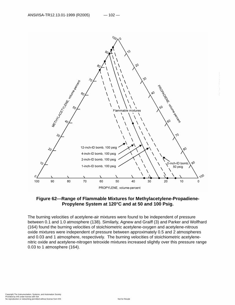
ANSI/ISA-TR12.13.01-1999 (R2005) — 102 —
Copyright The InstrumProvided by IHS underNo reproduction or net
--`,,```,,,,````-`-`,,`,,`,`,,`---
Figure 62—Range of Flammable Mixtures for Methylacetylene-Propadiene-Propylene System at 120°C and at 50 and 100 Psig.
The burning velocities of acetylene-air mixtures were found to be independent of pressure between 0.1 and 1.0 atmosphere (138). Similarly, Agnew and Graiff (3) and Parker and Wolfhard (164) found the burning velocities of stoichiometric acetylene-oxygen and acetylene-nitrous oxide mixtures were independent of pressure between approximately 0.5 and 2 atmospheres and 0.03 and 1 atmosphere, respectively. The burning velocities of stoichiometric acetylene-nitric oxide and acetylene-nitrogen tetroxide mixtures increased slightly over this pressure range 0.03 to 1 atmosphere (164).
entation, Systems, and Automation Society license with ISA
Not for Resaleworking permitted without license from IHS
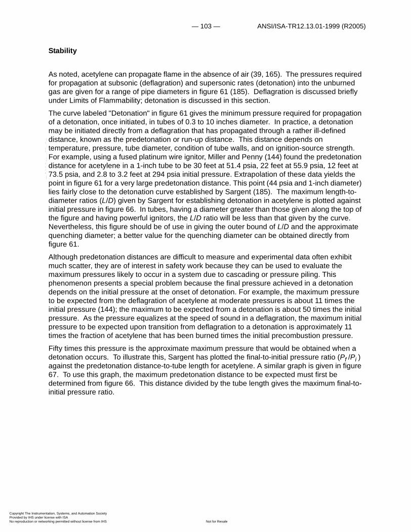
— 103 — ANSI/ISA-TR12.13.01-1999 (R2005)
Copyright The InstrumProvided by IHS underNo reproduction or net
Stability
As noted, acetylene can propagate flame in the absence of air (39, 165). The pressures required for propagation at subsonic (deflagration) and supersonic rates (detonation) into the unburned gas are given for a range of pipe diameters in figure 61 (185). Deflagration is discussed briefly under Limits of Flammability; detonation is discussed in this section.
The curve labeled "Detonation" in figure 61 gives the minimum pressure required for propagation of a detonation, once initiated, in tubes of 0.3 to 10 inches diameter. In practice, a detonation may be initiated directly from a deflagration that has propagated through a rather ill-defined distance, known as the predetonation or run-up distance. This distance depends on temperature, pressure, tube diameter, condition of tube walls, and on ignition-source strength. For example, using a fused platinum wire ignitor, Miller and Penny (144) found the predetonation distance for acetylene in a 1-inch tube to be 30 feet at 51.4 psia, 22 feet at 55.9 psia, 12 feet at 73.5 psia, and 2.8 to 3.2 feet at 294 psia initial pressure. Extrapolation of these data yields the point in figure 61 for a very large predetonation distance. This point (44 psia and 1-inch diameter) lies fairly close to the detonation curve established by Sargent (185). The maximum length-to-diameter ratios (L/D) given by Sargent for establishing detonation in acetylene is plotted against initial pressure in figure 66. In tubes, having a diameter greater than those given along the top of the figure and having powerful ignitors, the L/D ratio will be less than that given by the curve. Nevertheless, this figure should be of use in giving the outer bound of L/D and the approximate quenching diameter; a better value for the quenching diameter can be obtained directly from figure 61.
Although predetonation distances are difficult to measure and experimental data often exhibit much scatter, they are of interest in safety work because they can be used to evaluate the maximum pressures likely to occur in a system due to cascading or pressure piling. This phenomenon presents a special problem because the final pressure achieved in a detonation depends on the initial pressure at the onset of detonation. For example, the maximum pressure to be expected from the deflagration of acetylene at moderate pressures is about 11 times the initial pressure (144); the maximum to be expected from a detonation is about 50 times the initial pressure. As the pressure equalizes at the speed of sound in a deflagration, the maximum initial pressure to be expected upon transition from deflagration to a detonation is approximately 11 times the fraction of acetylene that has been burned times the initial precombustion pressure.
Fifty times this pressure is the approximate maximum pressure that would be obtained when a detonation occurs. To illustrate this, Sargent has plotted the final-to-initial pressure ratio (Pf /Pi ) against the predetonation distance-to-tube length for acetylene. A similar graph is given in figure 67. To use this graph, the maximum predetonation distance to be expected must first be determined from figure 66. This distance divided by the tube length gives the maximum final-to-initial pressure ratio.
--`,,```,,,,````-`-`,,`,,`,`,,`---
entation, Systems, and Automation Society license with ISA
Not for Resaleworking permitted without license from IHS
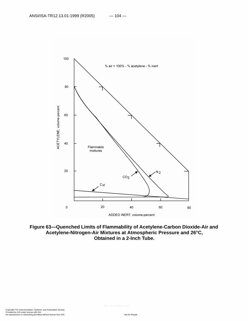
ANSI/ISA-TR12.13.01-1999 (R2005) — 104 —
Copyright The InstrumProvided by IHS underNo reproduction or net
Figure 63—Quenched Limits of Flammability of Acetylene-Carbon Dioxide-Air and Acetylene-Nitrogen-Air Mixtures at Atmospheric Pressure and 26°C,
Obtained in a 2-Inch Tube.
entation, Systems, and Automation Society license with ISA
Not for Resaleworking permitted without license from IHS
--`,,```,,,,````-`-`,,`,,`,`,,`---

— 105 — ANSI/ISA-TR12.13.01-1999 (R2005)
Copyright The InstrumProvided by IHS underNo reproduction or net
--`,,```,,,,````-`-`,,`,,`,`,,`---
Figure 64—Minimum Autoignition Temperatures of Acetylene-Air and Acetylene-Oxygen Mixtures at Atmospheric and Elevated Pressures.
entation, Systems, and Automation Society license with ISA
Not for Resaleworking permitted without license from IHS

ANSI/ISA-TR12.13.01-1999 (R2005) — 106 —
Copyright The InstrumProvided by IHS underNo reproduction or net
--`,,```,,,,````-`-`,,`,,`,`,,`---
Figure 65—Burning Velocity of Acetylene-Air Mixtures at Atmospheric Pressure and Room Temperature.
AROMATIC HYDROCARBONS (CnH2n–6)
Limits in Air
The combustibles considered in this section are listed in table 11, with pertinent properties. At atmospheric pressure and room temperature, the lower limits of flammability of the aromatic hydrocarbons are approximately 50±2 mg/l (0.050±0.002 oz combustible vapor per cubic foot of air).
The lower limit of toluene was determined by Zabetakis and coworkers in air at 30°, 100°, and 200°C (235, 247); the variation in lower limit with temperature is given by equations (31) and (33) derived for paraffin hydrocarbons, and the corresponding curves of figure 23. For example, L200°C/L30°C was found to be 1.07/1.24 or 0.86; the ratio predicted by the curve in figure 23 is 0.87.
entation, Systems, and Automation Society license with ISA
Not for Resaleworking permitted without license from IHS

— 107 — ANSI/ISA-TR12.13.01-1999 (R2005)
Copyright The InstrumProvided by IHS underNo reproduction or net
Figure 66—Maximum L/D Ratio Required for Transition of a Deflagration to a Detonation in Acetylene Vapor at 60°F and from 10 to 70 Psia.
Table 11 — Properties of selected aromatic hydrocarbons
CombustibleFormula M Sp gr
(Air=1)Cst in air (vol pct)
Net�Hc
Lower limit in air1 Upper limit in air1
L100(vol pct)
U100(vol pct)
Benzene C6H6 78.11 2.69 2.72 757.5 1.3 .48 47 7.9 2.9 300
Toluene C7H8 92.13 3.18 2.27 901.5 1.2 .53 50 7.1 3.1 310
Ethyl benzene C8H10 106.16 3.67 1.96 1048.5 1.0 .51 48 6.7 3.4 340
o-Xylene C8H10 106.16 3.67 1.96 1045.9 1.1 .56 53 6.4 3.3 320
m-Xylene C8H10 106.16 3.67 1.96 1045.5 1.1 .56 53 6.4 3.3 320
p-Xylene C8H10 106.16 3.67 1.96 1045.7 1.1 .56 53 6.6 3.4 340
Cumene C9H12 120.19 4.15 1.72 1194.2 .88 .51 48 6.5 3.8 370
p-Cymene C10H14 134.21 4.63 1.53 1341.8 .85 .56 51 6.5 3.6 350
Kcalmole------------ �
L100Cst
------------ L mg1
-------� �� �
U100Cst
------------- U mg1
-------� �� �
entation, Systems, and Automation Society license with ISA
Not for Resaleworking permitted without license from IHS
--`,,```,,,,````-`-`,,`,,`,`,,`---
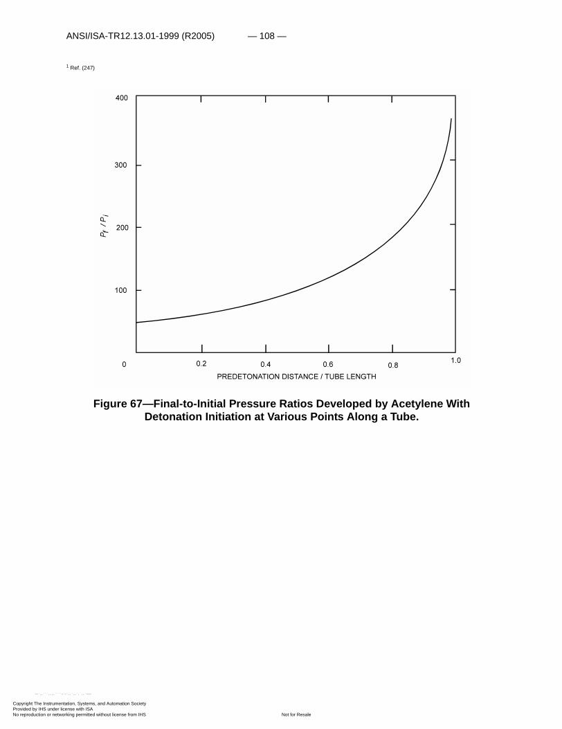
ANSI/ISA-TR12.13.01-1999 (R2005) — 108 —
Copyright The InstrumProvided by IHS underNo reproduction or net
--`,,```,,,,``
1 Ref. (247)
Figure 67—Final-to-Initial Pressure Ratios Developed by Acetylene With Detonation Initiation at Various Points Along a Tube.
entation, Systems, and Automation Society license with ISA
Not for Resaleworking permitted without license from IHS
``-`-`,,`,,`,`,,`---

— 109 — ANSI/ISA-TR12.13.01-1999 (R2005)
Copyright The InstrumProvided by IHS underNo reproduction or net
--`,,```,,,,````-`-`,,`,,`,`,,`---
The upper limits of the aromatics considered here at 100°C are included in table 11 (247). These were obtained at atmospheric pressure in a 2-inch-diameter tube, open at one end. Butler and Webb obtained upper limit data on a commercial grade cumene (93.3 pct cumene) in air at elevated temperatures and atmospheric and elevated pressures in a closed bomb (31). Their values range from 8.8 percent cumene (80°C and atmospheric pressure) to 10.8 percent cumene (146°C and 100 psig pressure).
entation, Systems, and Automation Society license with ISA
Not for Resaleworking permitted without license from IHS
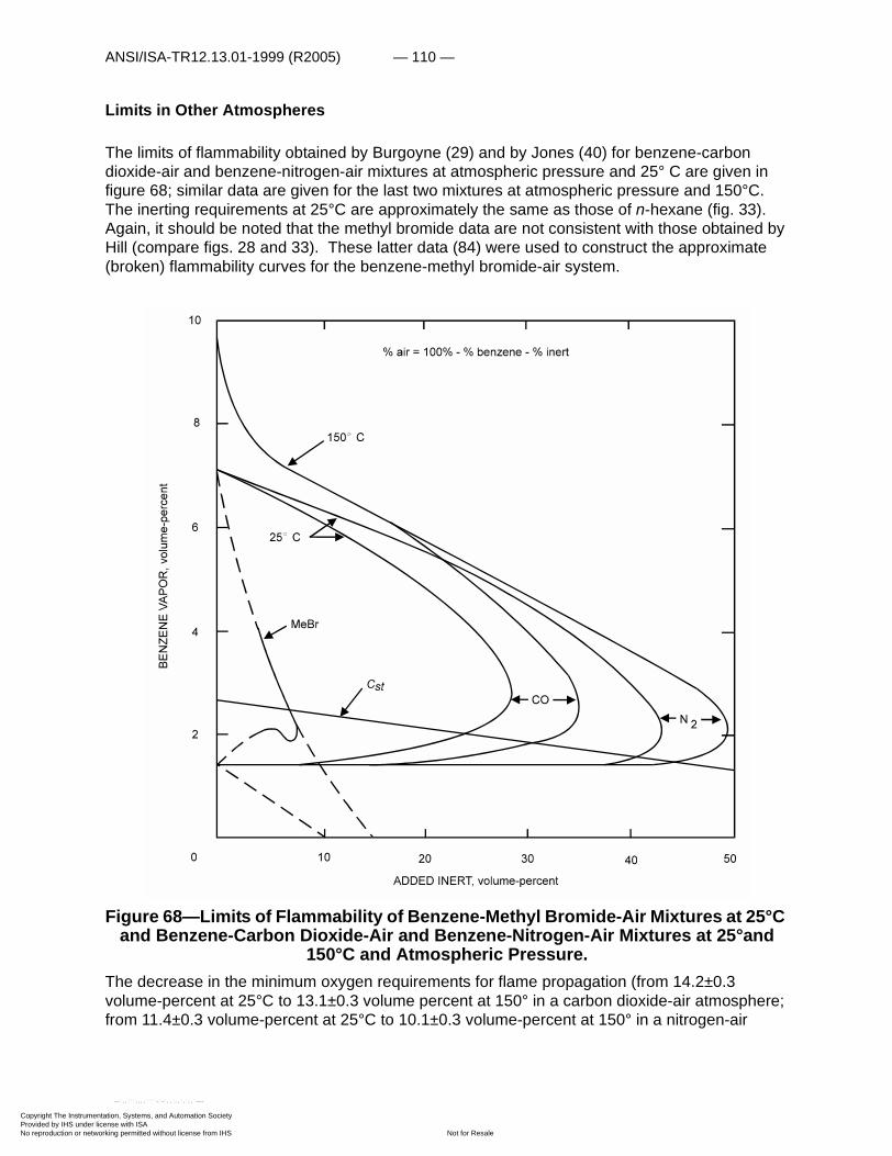
ANSI/ISA-TR12.13.01-1999 (R2005) — 110 —
Copyright The InstrumProvided by IHS underNo reproduction or net
Limits in Other Atmospheres
The limits of flammability obtained by Burgoyne (29) and by Jones (40) for benzene-carbon dioxide-air and benzene-nitrogen-air mixtures at atmospheric pressure and 25° C are given in figure 68; similar data are given for the last two mixtures at atmospheric pressure and 150°C. The inerting requirements at 25°C are approximately the same as those of n-hexane (fig. 33). Again, it should be noted that the methyl bromide data are not consistent with those obtained by Hill (compare figs. 28 and 33). These latter data (84) were used to construct the approximate (broken) flammability curves for the benzene-methyl bromide-air system.
Figure 68—Limits of Flammability of Benzene-Methyl Bromide-Air Mixtures at 25°C and Benzene-Carbon Dioxide-Air and Benzene-Nitrogen-Air Mixtures at 25°and
150°C and Atmospheric Pressure.The decrease in the minimum oxygen requirements for flame propagation (from 14.2±0.3 volume-percent at 25°C to 13.1±0.3 volume percent at 150° in a carbon dioxide-air atmosphere; from 11.4±0.3 volume-percent at 25°C to 10.1±0.3 volume-percent at 150° in a nitrogen-air
entation, Systems, and Automation Society license with ISA
Not for Resaleworking permitted without license from IHS
--`,,```,,,,````-`-`,,`,,`,`,,`---
— 111 — ANSI/ISA-TR12.13.01-1999 (R2005)
Copyright The InstrumProvided by IHS underNo reproduction or net
atmosphere) is within the range predicted by the modified Burgess-Wheeler law (equation (35), fig. 23).
The limits of flammability of orthoxylene (C6H4�(CH3)2)-water-hydrogen peroxide mixtures were determined at 154°C and 1 atmosphere pressure by Martindill, Lang, and Zabetakis (140). The data are presented in a triangular plot in figure 69; compositions are expressed in mole-percent as in the original presentation. This system has no lower limit mixtures, as a flame can be initiated in hydrogen peroxide vapors (186). As a 90-weight-percent hydrogen peroxide was actually used to obtain these flammability data, all compositions were calculated to yield values based on a 100-percent hydrogen peroxide content. This could be done here because only three components are considered. Where four components are considered, the flammability data can be presented in a three-dimensional plot; if two of the components appear in fixed proportions, a triangular plot can be used with the two components (for example, 90-weight-percent hydrogen peroxide) considered as a single component. Such a plot is presented in figure 70 for 90-weight-percent hydrogen peroxide-orthoxylene-formic acid (HCOOH) at 154°C and 1 atmosphere. This was considered to be a plane in a regular tetrahedron in the original article and is therefore not a regular triangle. As before, only an upper limit curve is given because 90-weight-percent hydrogen peroxide is flammable. In addition, a calculated curve based on Le Chatelier's rule is given, as is the upper limit curve obtained with decomposed hydrogen peroxide. Decomposition of the peroxide lowers the upper limit appreciably and yields a system which has a lower limit of flammability (not determined in this study).
Autoignition
The minimum autoignition temperatures of a series of aromatic hydrocarbons in air at atmospheric pressure are given in figure 71 as a function of the correlation parameter Lave. This parameter was determined by use of equation (49), treating the benzene ring as a –CH3 group (241). When the benzene ring contains two side groups, Lave is determined first for the side group that yields the largest average value and to this is added 1/2, 1/3, or 1/4 of the average chain length of the second side group; (1/2, 1/3, and 1/4 correspond to the ortho-, meta-, and para-positions, respectively). The data again fall into high- and low-temperature regions (fig. 43).
Burning Rate
Burning rates and detonation velocities of benzene in air and oxygen appear to be approximately the same as those of the higher paraffin hydrocarbons. For example, the results of Golovina and Fyodorov (211) show that the maximum burning velocities of benzene in nitrogen-oxygen mixtures range from about 295 cm/sec in oxygen to 45 cm/sec in air; the maximum burning velocities of hexane in various nitrogen-oxygen mixtures range from about 260 cm/sec in oxygen to 40 cm/sec in air. Similarly, Fraser (61) found the maximum detonation velocities of benzene and n-octane in oxygen to be 2,510 and 2,540 m/sec, respectively.
entation, Systems, and Automation Society license with ISA
Not for Resaleworking permitted without license from IHS
--`,,```,,,,````-`-`,,`,,`,`,,`---

ANSI/ISA-TR12.13.01-1999 (R2005) — 112 —
Copyright The InstrumProvided by IHS underNo reproduction or net
--`,,```,,,,````-`-`,,`,,`,`,,`---
Figure 69—Limits of Flammability of H2O2-C6H4�(CH3)2-H2O at 154°C and 1 Atmosphere Pressure.
entation, Systems, and Automation Society license with ISA
Not for Resaleworking permitted without license from IHS
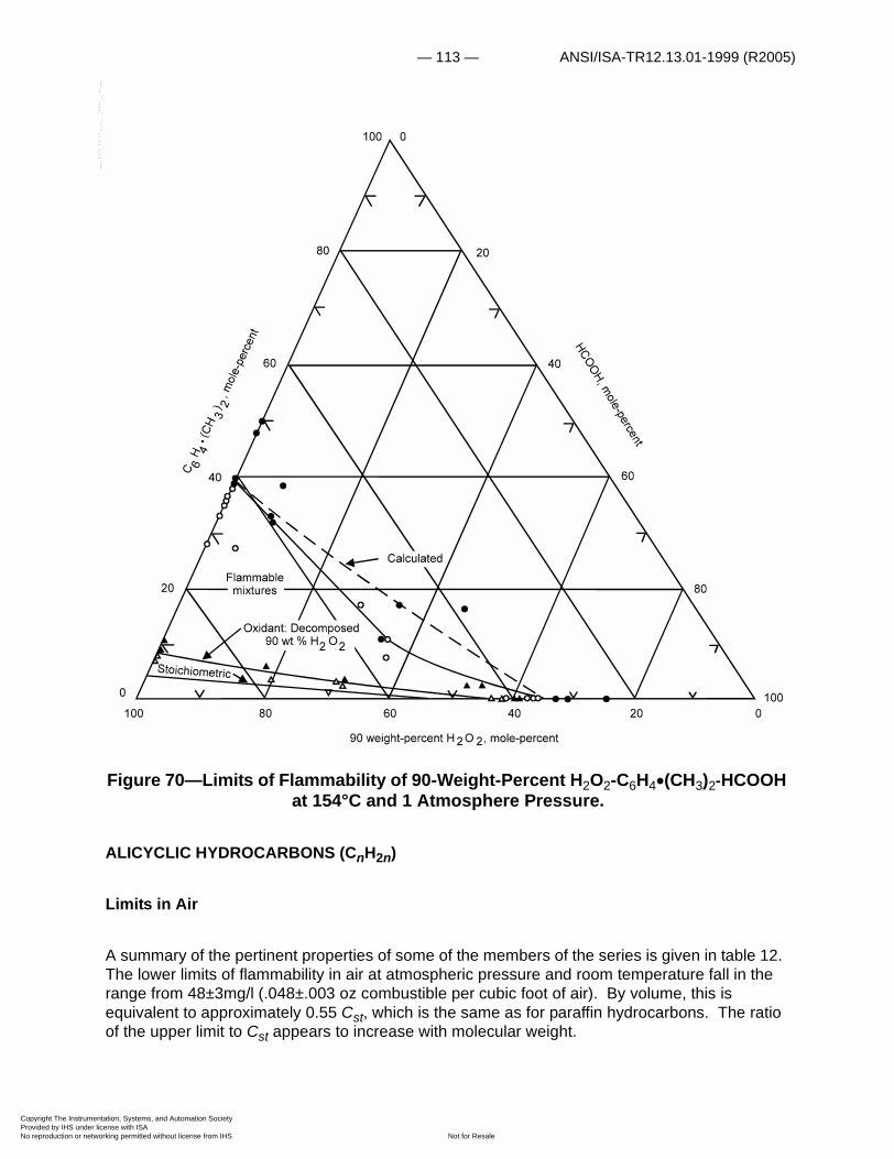
— 113 — ANSI/ISA-TR12.13.01-1999 (R2005)
Copyright The InstrumProvided by IHS underNo reproduction or net
--`,,
Figure 70—Limits of Flammability of 90-Weight-Percent H2O2-C6H4�(CH3)2-HCOOH at 154°C and 1 Atmosphere Pressure.
ALICYCLIC HYDROCARBONS (CnH2n)
Limits in Air
A summary of the pertinent properties of some of the members of the series is given in table 12. The lower limits of flammability in air at atmospheric pressure and room temperature fall in the range from 48±3mg/l (.048±.003 oz combustible per cubic foot of air). By volume, this is equivalent to approximately 0.55 Cst, which is the same as for paraffin hydrocarbons. The ratio of the upper limit to Cst appears to increase with molecular weight.
```,,,,````-`-`,,`,,`,`,,`---
entation, Systems, and Automation Society license with ISA
Not for Resaleworking permitted without license from IHS
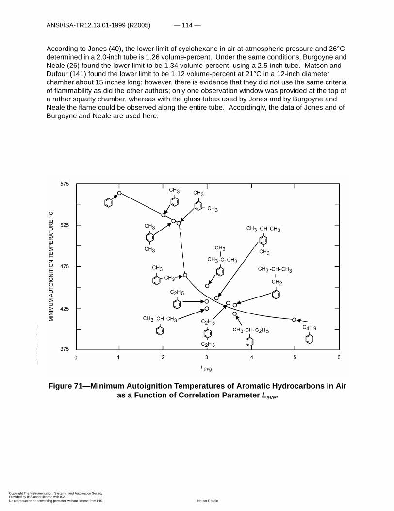
ANSI/ISA-TR12.13.01-1999 (R2005) — 114 —
Copyright The InstrumProvided by IHS underNo reproduction or net
--`,,```,,,,````-`-`,,`,,`,`,,`---
According to Jones (40), the lower limit of cyclohexane in air at atmospheric pressure and 26°C determined in a 2.0-inch tube is 1.26 volume-percent. Under the same conditions, Burgoyne and Neale (26) found the lower limit to be 1.34 volume-percent, using a 2.5-inch tube. Matson and Dufour (141) found the lower limit to be 1.12 volume-percent at 21°C in a 12-inch diameter chamber about 15 inches long; however, there is evidence that they did not use the same criteria of flammability as did the other authors; only one observation window was provided at the top of a rather squatty chamber, whereas with the glass tubes used by Jones and by Burgoyne and Neale the flame could be observed along the entire tube. Accordingly, the data of Jones and of Burgoyne and Neale are used here.
Figure 71—Minimum Autoignition Temperatures of Aromatic Hydrocarbons in Air as a Function of Correlation Parameter Lave.
entation, Systems, and Automation Society license with ISA
Not for Resaleworking permitted without license from IHS
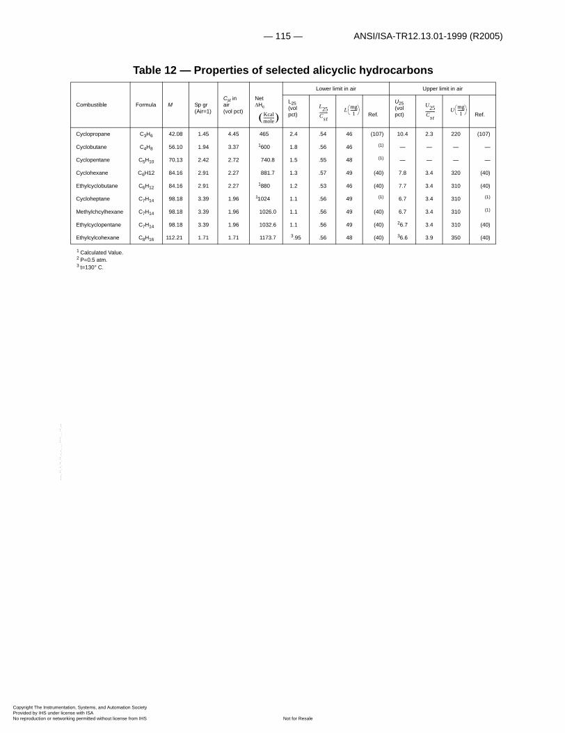
— 115 — ANSI/ISA-TR12.13.01-1999 (R2005)
Copyright The InstrumProvided by IHS underNo reproduction or net
Table 12 — Properties of selected alicyclic hydrocarbons
1 Calculated Value.2 P=0.5 atm.3 t=130° C.
Combustible Formula M Sp gr (Air=1)
Cst in air (vol pct)
Net�Hc
Lower limit in air Upper limit in air
L25(vol pct) Ref.
U25(vol pct) Ref.
Cyclopropane C3H6 42.08 1.45 4.45 465 2.4 .54 46 (107) 10.4 2.3 220 (107)
Cyclobutane C4H8 56.10 1.94 3.37 1600 1.8 .56 46 (1) — — — —
Cyclopentane C5H10 70.13 2.42 2.72 740.8 1.5 .55 48 (1) — — — —
Cyclohexane C6H12 84.16 2.91 2.27 881.7 1.3 .57 49 (40) 7.8 3.4 320 (40)
Ethylcyclobutane C6H12 84.16 2.91 2.27 1880 1.2 .53 46 (40) 7.7 3.4 310 (40)
Cycloheptane C7H14 98.18 3.39 1.96 11024 1.1 .56 49 (1) 6.7 3.4 310 (1)
Methylchcylhexane C7H14 98.18 3.39 1.96 1026.0 1.1 .56 49 (40) 6.7 3.4 310 (1)
Ethylcyclopentane C7H14 98.18 3.39 1.96 1032.6 1.1 .56 49 (40) 26.7 3.4 310 (40)
Ethylcylcohexane C8H16 112.21 1.71 1.71 1173.7 3.95 .56 48 (40) 36.6 3.9 350 (40)
Kcalmole------------ �
L25Cst--------- L mg
1-------� �� �
U25Cst---------- U mg
1-------� �� �
--`,,```,,,,````-`-`,,`,,`,`,,`---
entation, Systems, and Automation Society license with ISA
Not for Resaleworking permitted without license from IHS

ANSI/ISA-TR12.13.01-1999 (R2005) — 116 —
Copyright The InstrumProvided by IHS underNo reproduction or net
--`,,```,,,,
Figure 72—Limits of Flammability of Cyclopropane-Carbon Dioxide-Air, Cyclopropane-Nitrogen-Air, and Cyclopropane Helium-Air Mixtures at 25°C and
Atmospheric Pressure.
Limits in Other Atmospheres
The limits of flammability of cyclopropane-carbon dioxide-air, cyclopropane-nitrogen-air, and cyclopropane-helium-air mixtures at 25°C and atmospheric pressure are given in figure 72 (106). The first two curves are similar to those obtained with paraffin hydrocarbons (fig. 35).
The limits of flammability of cyclopropane-helium-oxygen and cyclopropane-nitrous oxide-oxygen mixtures at 25°C and atmospheric pressure are given in figure 73 (106). The latter curve differs from the former, as both additives are oxidants (oxygen and nitrous oxide).
The limits of flammability of cyclopropane-helium-nitrous oxide mixtures at 25°C and atmospheric pressure are given in figure 74 (106). Here the minimum oxidant concentration (nitrous oxide) required for flame propagation is approximately twice the corresponding concentration of oxygen in the systems cyclopropane-helium-air (fig. 72) and cyclopropane-helium-oxygen (fig. 73).
entation, Systems, and Automation Society license with ISA
Not for Resaleworking permitted without license from IHS
````-`-`,,`,,`,`,,`---
— 117 — ANSI/ISA-TR12.13.01-1999 (R2005)
Copyright The InstrumProvided by IHS underNo reproduction or net
--`,,```,,,,````-`-`,,`,,`,`,,`---
ALCOHOLS (CnH2n+1OH)
Limits in Air
The alcohols considered here are listed in table 13 together with L25° and U25°. The ratios L25°/Cst are approximately 0.5. However, the L (mg/l) values decrease with increase in molecular weight. If L* is taken to be the weight of combustible material (exclusive of the oxygen in the molecule) per liter of air, then for the simple alcohols:
. (54)
This equation gives the values listed in parentheses in the mg/l column; these are in fair agreement with the values obtained for the saturated hydrocarbons. Approximate L (mg/l) values can be obtained from the higher hydrocarbon values given in figure 22 by multiplying these by the ratio M/(M–16). Further, figure 19 can be used to obtain L* and L values in volume-percent.
For example, at 25°C, L* is about 47 mg/l from figure 22; the corresponding L*25 from figure19 for
ethyl alcohol (M=46) is 2.2 volume-percent. Then, from equation (54), L is 3.4 volume-percent; the measured value is 3.3 volume-percent.
The lower limits of methyl alcohol have been determined by Scott and coworkers at 25°, 100°, and 200°C (192). The values at these three temperatures are 6.7, 6.5, and 5.9 volume-percent, respectively. The calculated values obtained from the modified Burgess-Wheeler law (fig. 23) at 100° and 200°C are 6.4 and 5.8 volume-percent, respectively.
L* LM 16–M
-----------------=
entation, Systems, and Automation Society license with ISA
Not for Resaleworking permitted without license from IHS

ANSI/ISA-TR12.13.01-1999 (R2005) — 118 —
Copyright The InstrumProvided by IHS underNo reproduction or net
--`,,```,,,,````-`-`,,`,,`,`,,`---
Figure 73—Limits of Flammability of Cyclopropane-Helium-Oxygen and Cyclopropane-Nitrous Oxide-Oxygen Mixtures at 25°C and Atmospheric Pressure.
entation, Systems, and Automation Society license with ISA
Not for Resaleworking permitted without license from IHS

— 119 — ANSI/ISA-TR12.13.01-1999 (R2005)
Copyright The InstrumProvided by IHS underNo reproduction or net
--`,,```,,,,`
Figure 74—Limits of Flammability of Cyclopropane-Helium-Nitrous Oxide Mixtures at 25°C and Atmospheric Pressure.
Limits in Other Atmospheres
The limits of flammability of methyl alcohol-carbon dioxide-air and methyl alcohol-nitrogen-air mixtures at atmospheric pressure and 25° and 50°C are given in figure 75; flammability determinations on mixtures containing more than 15 percent methyl alcohol vapor were conducted at 50°C. The maximum amounts of carbon dioxide and nitrogen required to prevent flame propagation in these mixtures were compared with the corresponding maxima for paraffin hydrocarbons (figs. 28-35); it was found that appreciably more inert is required to make mixtures containing methyl alcohol nonflammable. Conversely methyl alcohol requires less oxygen to form flammable mixtures, at a given temperature and pressure, than paraffin hydrocarbons do. This may be due in part to the oxygen of the alcohol molecule. For the simple alcohols, we have:
. (55)CnH2n 1+ OH 1.5nO2 nCO2 n 1+ �H2O+�+
entation, Systems, and Automation Society license with ISA
Not for Resaleworking permitted without license from IHS
```-`-`,,`,,`,`,,`---

ANSI/ISA-TR12.13.01-1999 (R2005) — 120 —
Copyright The InstrumProvided by IHS underNo reproduction or net
Figure 75—Limits of Flammability of Methyl Alcohol-Carbon Dioxide-Air and Methyl Alcohol-Nitrogen-Air Mixtures at 25°C and Atmospheric Pressure.
(Broken Curve at 50°C and Atmospheric Pressure.)
--`,,```,,,,````-`-`,,`,,`,`,,`---
entation, Systems, and Automation Society license with ISA
Not for Resaleworking permitted without license from IHS
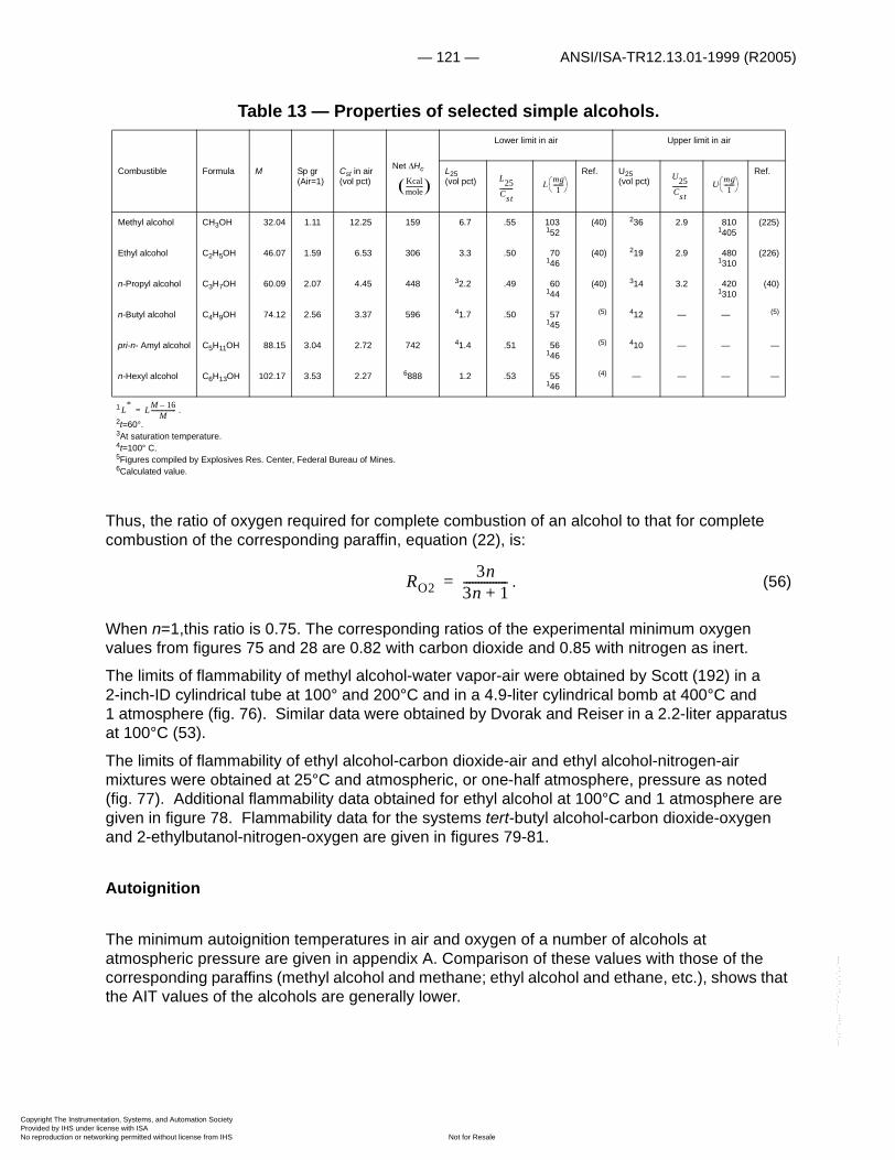
— 121 — ANSI/ISA-TR12.13.01-1999 (R2005)
Copyright The InstrumProvided by IHS underNo reproduction or net
--`,,```,,,,````-`-`,,`,,`,`,,`---
Table 13 — Properties of selected simple alcohols.
1 .2t=60°.3At saturation temperature.4t=100° C.5Figures compiled by Explosives Res. Center, Federal Bureau of Mines.6Calculated value.
Thus, the ratio of oxygen required for complete combustion of an alcohol to that for complete combustion of the corresponding paraffin, equation (22), is:
. (56)
When n=1,this ratio is 0.75. The corresponding ratios of the experimental minimum oxygen values from figures 75 and 28 are 0.82 with carbon dioxide and 0.85 with nitrogen as inert.
The limits of flammability of methyl alcohol-water vapor-air were obtained by Scott (192) in a 2-inch-ID cylindrical tube at 100° and 200°C and in a 4.9-liter cylindrical bomb at 400°C and 1 atmosphere (fig. 76). Similar data were obtained by Dvorak and Reiser in a 2.2-liter apparatus at 100°C (53).
The limits of flammability of ethyl alcohol-carbon dioxide-air and ethyl alcohol-nitrogen-air mixtures were obtained at 25°C and atmospheric, or one-half atmosphere, pressure as noted (fig. 77). Additional flammability data obtained for ethyl alcohol at 100°C and 1 atmosphere are given in figure 78. Flammability data for the systems tert-butyl alcohol-carbon dioxide-oxygen and 2-ethylbutanol-nitrogen-oxygen are given in figures 79-81.
Autoignition
The minimum autoignition temperatures in air and oxygen of a number of alcohols at atmospheric pressure are given in appendix A. Comparison of these values with those of the corresponding paraffins (methyl alcohol and methane; ethyl alcohol and ethane, etc.), shows that the AIT values of the alcohols are generally lower.
Combustible Formula M Sp gr (Air=1)
Cst in air (vol pct)
Net �Hc
Lower limit in air Upper limit in air
L25(vol pct)
Ref. U25(vol pct)
Ref.
Methyl alcohol CH3OH 32.04 1.11 12.25 159 6.7 .55 103152
(40) 236 2.9 8101405
(225)
Ethyl alcohol C2H5OH 46.07 1.59 6.53 306 3.3 .50 70146
(40) 219 2.9 4801310
(226)
n-Propyl alcohol C3H7OH 60.09 2.07 4.45 448 32.2 .49 60144
(40) 314 3.2 4201310
(40)
n-Butyl alcohol C4H9OH 74.12 2.56 3.37 596 41.7 .50 57145
(5) 412 — — (5)
pri-n- Amyl alcohol C5H11OH 88.15 3.04 2.72 742 41.4 .51 56146
(5) 410 — — —
n-Hexyl alcohol C6H13OH 102.17 3.53 2.27 6888 1.2 .53 55146
(4) — — — —
Kcalmole------------ � L25
Cst--------- L mg
1-------� �� �
U25Cst---------- U mg
1-------� �� �
L* LM 16–M
-----------------=
RO23n
3n 1+---------------=
entation, Systems, and Automation Society license with ISA
Not for Resaleworking permitted without license from IHS

ANSI/ISA-TR12.13.01-1999 (R2005) — 122 —
Copyright The InstrumProvided by IHS underNo reproduction or net
--`,,```,,,,````-`-`,,`,,`,`,,`---
Figure 76—Limits of Flammability of Methyl Alcohol-Water Vapor-Air Mixtures at 100°, 200°, and 400°C and Atmospheric Pressure.
entation, Systems, and Automation Society license with ISA
Not for Resaleworking permitted without license from IHS
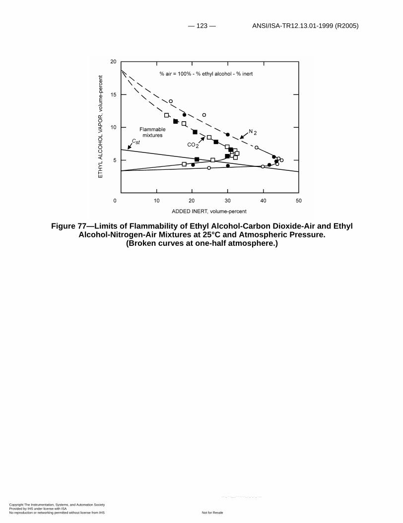
— 123 — ANSI/ISA-TR12.13.01-1999 (R2005)
Copyright The InstrumProvided by IHS underNo reproduction or net
Figure 77—Limits of Flammability of Ethyl Alcohol-Carbon Dioxide-Air and Ethyl Alcohol-Nitrogen-Air Mixtures at 25°C and Atmospheric Pressure.
(Broken curves at one-half atmosphere.)
entation, Systems, and Automation Society license with ISA
Not for Resaleworking permitted without license from IHS
--`,,```,,,,````-`-`,,`,,`,`,,`---

ANSI/ISA-TR12.13.01-1999 (R2005) — 124 —
Copyright The InstrumProvided by IHS underNo reproduction or net
--`,,```,,,,````-`-`,,`,,`,`,,`---
Figure 78—Limits of Flammability of Ethyl Alcohol-Water Vapor-Air Mixtures at 100°C and Atmospheric Pressure.
Burning Rate
The burning velocities of methyl and isopropyl alcohol in air were determined by Gibbs and Calcote for a range of mixture compositions at 25°C; the maximum burning velocities were found to be 50.4 and 41.4 cm/sec, respectively (68). These investigators also obtained the burning velocities of methyl and n-propyl alcohol at 100°C; the maximum values were 72.2 and 64.8 cm/sec, respectively. These values are in fair agreement with the corresponding values of the paraffin hydrocarbons.
The methyl alcohol liquid-burning rate obtained from equation (53) is in fair agreement with that obtained experimentally (fig. 52). The relatively low �Hc/�Hv ratios for the alcohols indicates that they should be characterized by low-burning rates in large pools.
entation, Systems, and Automation Society license with ISA
Not for Resaleworking permitted without license from IHS

— 125 — ANSI/ISA-TR12.13.01-1999 (R2005)
Copyright The InstrumProvided by IHS underNo reproduction or net
Figure 79—Limits of Flammability of tert-Butyl Alcohol-Water Vapor-Air Mixtures at 150°C and Atmospheric Pressure.
entation, Systems, and Automation Society license with ISA
Not for Resaleworking permitted without license from IHS
--`,,```,,,,````-`-`,,`,,`,`,,`---

ANSI/ISA-TR12.13.01-1999 (R2005) — 126 —
Copyright The InstrumProvided by IHS underNo reproduction or net
Figure 80—Limits of Flammability of tert-Butyl Alcohol-Carbon Dioxide-Oxygen Mixtures at 150°C and Atmospheric Pressure.
entation, Systems, and Automation Society license with ISA
Not for Resaleworking permitted without license from IHS
--`,,```,,,,````-`-`,,`,,`,`,,`---

— 127 — ANSI/ISA-TR12.13.01-1999 (R2005)
Copyright The InstrumProvided by IHS underNo reproduction or net
--`,,```,,,,````-`-`,,`,,`,`,,`---
Figure 81—Limits of Flammability of 2-Ethyl-butanol-Nitrogen-Oxygen Mixtures at 150°C and Atmospheric Pressure.
entation, Systems, and Automation Society license with ISA
Not for Resaleworking permitted without license from IHS
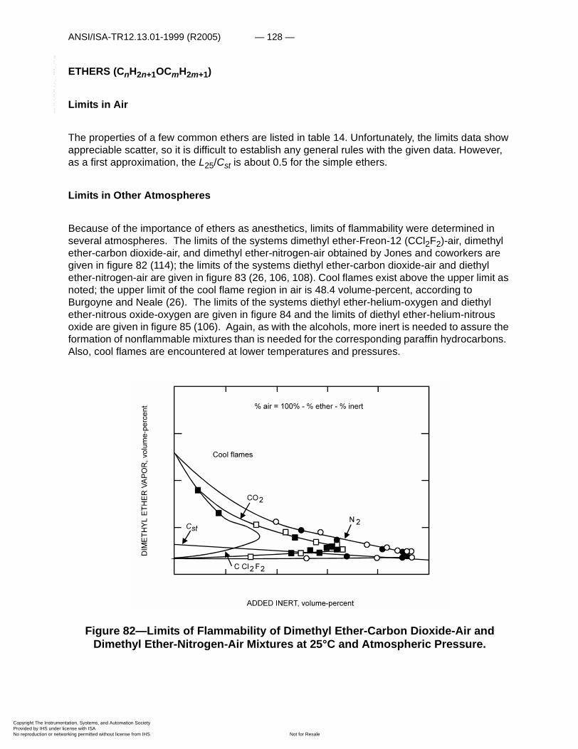
ANSI/ISA-TR12.13.01-1999 (R2005) — 128 —
Copyright The InstrumProvided by IHS underNo reproduction or net
--`,,```,,,,````-`-`,,`,,`,`,,`---
ETHERS (CnH2n+1OCmH2m+1)
Limits in Air
The properties of a few common ethers are listed in table 14. Unfortunately, the limits data show appreciable scatter, so it is difficult to establish any general rules with the given data. However, as a first approximation, the L25/Cst is about 0.5 for the simple ethers.
Limits in Other Atmospheres
Because of the importance of ethers as anesthetics, limits of flammability were determined in several atmospheres. The limits of the systems dimethyl ether-Freon-12 (CCl2F2)-air, dimethyl ether-carbon dioxide-air, and dimethyl ether-nitrogen-air obtained by Jones and coworkers are given in figure 82 (114); the limits of the systems diethyl ether-carbon dioxide-air and diethyl ether-nitrogen-air are given in figure 83 (26, 106, 108). Cool flames exist above the upper limit as noted; the upper limit of the cool flame region in air is 48.4 volume-percent, according to Burgoyne and Neale (26). The limits of the systems diethyl ether-helium-oxygen and diethyl ether-nitrous oxide-oxygen are given in figure 84 and the limits of diethyl ether-helium-nitrous oxide are given in figure 85 (106). Again, as with the alcohols, more inert is needed to assure the formation of nonflammable mixtures than is needed for the corresponding paraffin hydrocarbons. Also, cool flames are encountered at lower temperatures and pressures.
Figure 82—Limits of Flammability of Dimethyl Ether-Carbon Dioxide-Air and Dimethyl Ether-Nitrogen-Air Mixtures at 25°C and Atmospheric Pressure.
entation, Systems, and Automation Society license with ISA
Not for Resaleworking permitted without license from IHS

— 129 — ANSI/ISA-TR12.13.01-1999 (R2005)
Copyright The InstrumProvided by IHS underNo reproduction or net
Figure 83—Limits of Flammability of Diethyl Ether-Carbon Dioxide-Air and Diethyl Ether-Nitrogen-Air Mixtures at 25°C and Atmospheric Pressure.
Table 14 — Properties of selected ethers
1 .2Cool Flames: U25=53 vol pct.3Calculated value.4Cool flames:U25>16 vol pct.5Ref.(155).
Combustible Formula M Sp gr (Air=1)
Cst in air (vol pct)
Net �Hc
Lower limit in air Upper limit in air
L25(vol pct) Ref.
U25(vol pct) Ref.
Dimethyl ether CH3OCH3 46.07 1.59 6.53 316 3.4 .52 72147
(114) 27 4.1 760 (114)
Diethyl ether C2H5OC2H5 74.12 2.56 3.37 605 1.9 .56 64150
(40) 236 11 1880 (40)
Ethyl propyl ether
C2H5OC3H7 88.15 3.28 2.72 3750 1.7 .62 68156
(26) 49 3.3 390 (26)
Di-i-propyl ether C3H7OC3H7 102.17 3.53 2.27 5900 1.4 .57 60151
(40) 7.9 3.5 290 (40)
Divinyl ether C2H3OC2H3 70.09 2.42 4.02 31,770 1.7 .42 54142
(97) 27 6.7 1160 (97)
Kcalmole------------ �
L25Cst--------- L mg
1-------� �� �
U25Cst---------- U mg
1-------� �� �
L* LM 16–M
-----------------=
entation, Systems, and Automation Society license with ISA
Not for Resaleworking permitted without license from IHS
--`,,```,,,,````-`-`,,`,,`,`,,`---
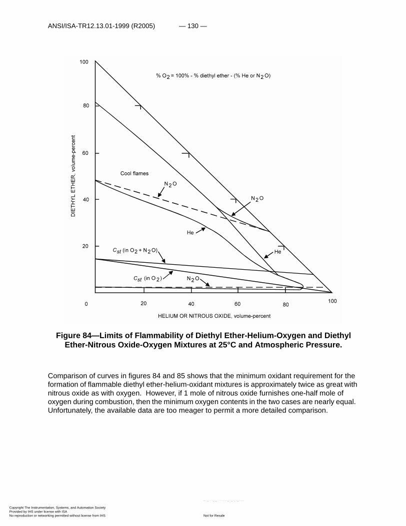
ANSI/ISA-TR12.13.01-1999 (R2005) — 130 —
Copyright The InstrumProvided by IHS underNo reproduction or net
Figure 84—Limits of Flammability of Diethyl Ether-Helium-Oxygen and Diethyl Ether-Nitrous Oxide-Oxygen Mixtures at 25°C and Atmospheric Pressure.
Comparison of curves in figures 84 and 85 shows that the minimum oxidant requirement for the formation of flammable diethyl ether-helium-oxidant mixtures is approximately twice as great with nitrous oxide as with oxygen. However, if 1 mole of nitrous oxide furnishes one-half mole of oxygen during combustion, then the minimum oxygen contents in the two cases are nearly equal. Unfortunately, the available data are too meager to permit a more detailed comparison.
entation, Systems, and Automation Society license with ISA
Not for Resaleworking permitted without license from IHS
--`,,```,,,,````-`-`,,`,,`,`,,`---

— 131 — ANSI/ISA-TR12.13.01-1999 (R2005)
Copyright The InstrumProvided by IHS underNo reproduction or net
--`,,```,,,,````-`-`,,`,,`,`,,`---
Autoignition
In general, ethers are readily ignited by hot surfaces. These combustibles usually have a lower ignition temperature in air and in oxygen than do the corresponding paraffins and alcohols. The available autoignition temperature data are included in Appendix A.
Since the ethers tend to form peroxides under a variety of conditions, they may appear to be unstable at room temperature (233).
Figure 85—Limits of Flammability of Diethyl Ether-Nitrous Oxide-Helium Mixtures at 25°C and Atmospheric Pressure.
ESTERS (CnH2n–1OOCmH2m+1)
The properties of several esters are listed in table 15. The ratio of the lower limit at 25°C to the stoichiometric concentration is about 0.55 for many of these compounds. This is the same ratio as in equation (21) for paraffin hydrocarbons. The lower limit values expressed in terms of the weight of combustible per liter of air (see section about alcohols) are listed in parentheses under L(mg/1). These are larger than the corresponding values for the hydrocarbons and alcohols. The inert requirements and minimum oxygen requirements for the first member of the series, methyl formate, are nearly the same as for methyl alcohol and dimethyl ether (figs. 76, 82, 86). This is not true of the other members for which data compiled at the Explosives Research Center are available—isobutyl formate and methyl acetate (figs. 87, 88). Accordingly, it is rather difficult to make additional generalizations for this series.
The autoignition temperatures of many esters in air and oxygen at atmospheric pressure are given in Appendix A. In general, the AIT values of the esters are lower than are those of the corresponding paraffins.
entation, Systems, and Automation Society license with ISA
Not for Resaleworking permitted without license from IHS

ANSI/ISA-TR12.13.01-1999 (R2005) — 132 —
Copyright The InstrumProvided by IHS underNo reproduction or net
--`,,```,,,,````-`-`,,`,,`,`,,`---
Table 15 — Properties of selected esters
1 .2Calculated value.3t = 90°C.4t = 100°C.5Figures compiled by Explosives Res. Center, Federal Bureau of Mines6P = 0.5 atm.
Combustible Formula M Sp gr (Air=1)
Cst in air (vol pct)
Net �Hc
Lower limit in airr
Upper limit in ai
L25(vol pct) Ref.
U25(vol pct)
Ref.
Methyl formate HCOOCH3 60.05 2.07 9.48 219 5.0 .53 142166
(111) 23.0 2.4 800 (111)
Ethyl formate HCOOC2H5 74.08 2.56 5.65 367 2.8 .50 95154
(40) 16.0 2.8 630 (40)
n-Butyl formate HCOOC4H9 102.13 3.53 3.12 2650 1.7 .54 79150
(40) 8.2 2.6 410 (40)
Methyl acetate CH3COOCH3 74.08 2.56 5.65 358 3.2 .57 106160
(40) 16.0 2.8 630 (40)
Ethyl acetate CH3COOC2H5 88.10 3.04 4.02 504 2.2 .55 88156
(40) 11.0 2.7 510 (175)
n-Propyl acetate CH3COOC3H7 102.13 3.53 3.12 2650 1.8 .58 83157
(40) 38.0 2.6 400 (40)
n-Butyl acetate CH3COOC4H9 116.16 4.01 2.55 — 41.4 .55 73153
(5) 48.0 3.1 450 (5)
n-Amyl acetate CH3COOC5H11 130.18 4.50 2.16 — 41.0 .51 65149
(5) 47.1 3.3 440 (5)
Methyl propionate C2H5COOCH3 88.10 3.04 4.02 — 2.4 .60 97162
(40) 13.0 63.2 580 (40)
Ethyl propionate C2H5COOC2H5 102.13 3.53 3.12 2650 1.8 .58 83157
(40) 11.0 63.5 510 (40)
Kcalmole------------ � L25
Cst--------- L mg
1-------� �� �
U25Cst---------- U mg
1-------� �� �
L* LM 16–M
-----------------=
entation, Systems, and Automation Society license with ISA
Not for Resaleworking permitted without license from IHS
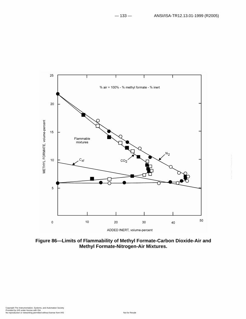
— 133 — ANSI/ISA-TR12.13.01-1999 (R2005)
Copyright The InstrumProvided by IHS underNo reproduction or net
--`,,```,,,,````-`-`,,`,,`,`,,`---
Figure 86—Limits of Flammability of Methyl Formate-Carbon Dioxide-Air and Methyl Formate-Nitrogen-Air Mixtures.
entation, Systems, and Automation Society license with ISA
Not for Resaleworking permitted without license from IHS
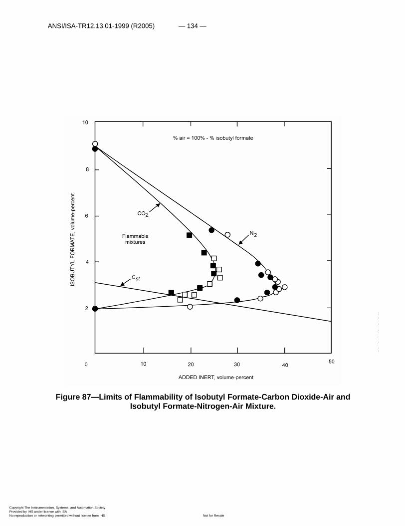
ANSI/ISA-TR12.13.01-1999 (R2005) — 134 —
Copyright The InstrumProvided by IHS underNo reproduction or net
--`,,```,,,,````-`-`,,`,,`,`,,`---
Figure 87—Limits of Flammability of Isobutyl Formate-Carbon Dioxide-Air and Isobutyl Formate-Nitrogen-Air Mixture.
entation, Systems, and Automation Society license with ISA
Not for Resaleworking permitted without license from IHS
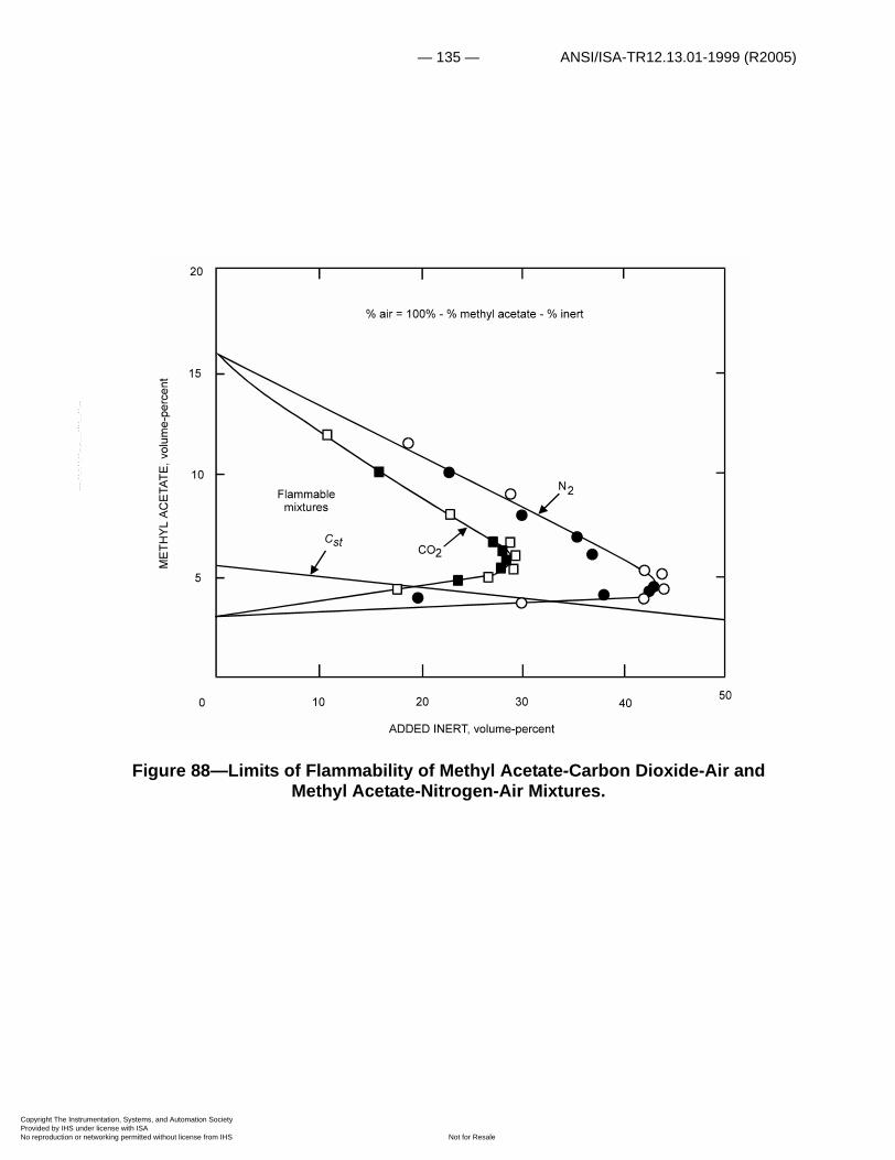
— 135 — ANSI/ISA-TR12.13.01-1999 (R2005)
Copyright The InstrumProvided by IHS underNo reproduction or net
--`,,```,,,,````-`-`,,`,,`,`,,`---
Figure 88—Limits of Flammability of Methyl Acetate-Carbon Dioxide-Air and Methyl Acetate-Nitrogen-Air Mixtures.
entation, Systems, and Automation Society license with ISA
Not for Resaleworking permitted without license from IHS

ANSI/ISA-TR12.13.01-1999 (R2005) — 136 —
Copyright The InstrumProvided by IHS underNo reproduction or net
--`,,```,,,,````-`-`,,`,,`,`,,`---
Figure 89—Effect of Temperature on Lower Limits of Flammability of MEK-Toluene Mixtures in Air at Atmospheric Pressure.
ALDEHYDES AND KETONES (CnH2nO)
Properties of some aldehydes and ketones are given in table 16. The ratio of the lower limit at 25°C in air to the stoichiometric composition is approximately 0.5.
Zabetakis, Cooper, and Furno found that the lower limits of methyl ethyl ketone (MEK) and MEK-toluene mixtures vary linearly with temperature between room temperature and 200°C (235). A summary of these data is given in figure 89; broken curves in this figure were obtained from the modified Burgess-Wheeler law, equation (33), taking the lower limit at 100°C as the reference value. Similar data were obtained for tetrahydrofuran (THF) and THF-toluene mixtures (fig. 90). In addition, it was shown that the systems MEK-toluene and THF-toluene obey Le Chatelier's law, equation (46). Calculated and experimental values for the preceding systems in air are given in figures 91 and 92.
The limits of the systems acetone-carbon dioxide-air, acetone-nitrogen-air, MEK-chlorobromomethane (CBM)-air , MEK-carbon dioxide-air, and MEK-nitrogen-air are given in figures 93 and 94. The data in these figures were obtained by Jones and coworkers (238).
entation, Systems, and Automation Society license with ISA
Not for Resaleworking permitted without license from IHS
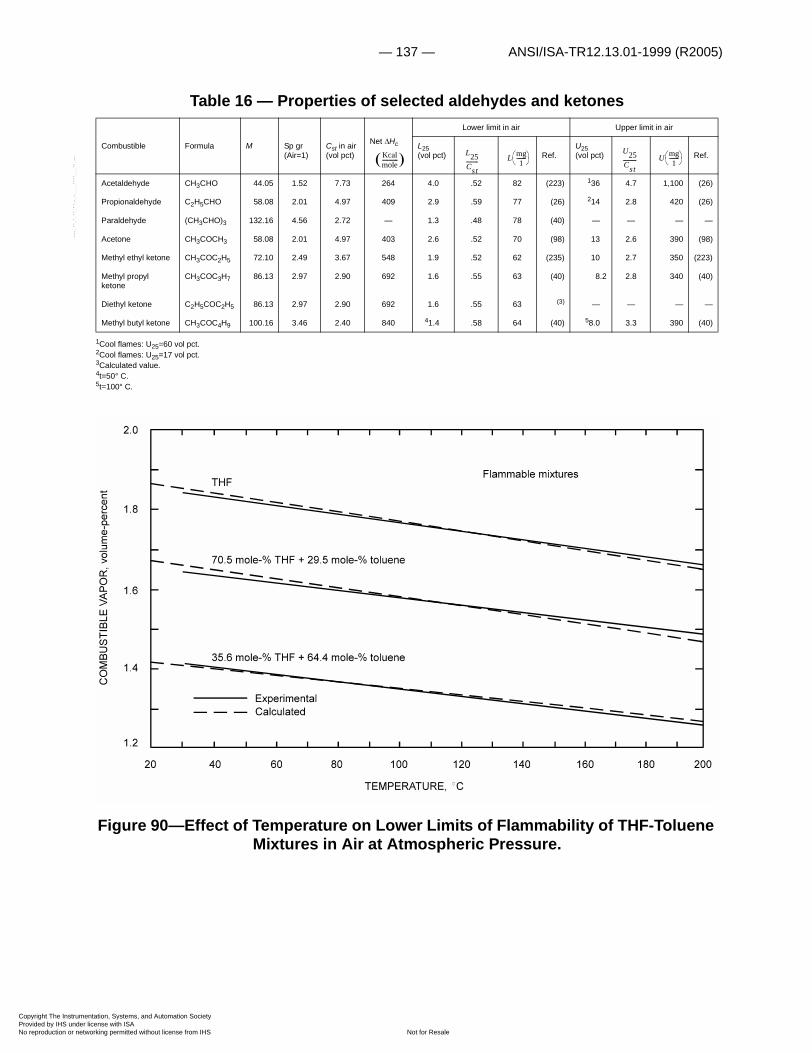
— 137 — ANSI/ISA-TR12.13.01-1999 (R2005)
Copyright The InstrumProvided by IHS underNo reproduction or net
--`,,```,,,,````-`-`,,`,,`,`,,`---
Table 16 — Properties of selected aldehydes and ketones
1Cool flames: U25=60 vol pct.2Cool flames: U25=17 vol pct.3Calculated value.4t=50° C.5t=100° C.
Figure 90—Effect of Temperature on Lower Limits of Flammability of THF-Toluene Mixtures in Air at Atmospheric Pressure.
Combustible Formula M Sp gr (Air=1)
Cst in air (vol pct)
Net �Hc
Lower limit in air Upper limit in air
L25(vol pct) Ref.
U25(vol pct) Ref.
Acetaldehyde CH3CHO 44.05 1.52 7.73 264 4.0 .52 82 (223) 136 4.7 1,100 (26)
Propionaldehyde C2H5CHO 58.08 2.01 4.97 409 2.9 .59 77 (26) 214 2.8 420 (26)
Paraldehyde (CH3CHO)3 132.16 4.56 2.72 — 1.3 .48 78 (40) — — — —
Acetone CH3COCH3 58.08 2.01 4.97 403 2.6 .52 70 (98) 13 2.6 390 (98)
Methyl ethyl ketone CH3COC2H5 72.10 2.49 3.67 548 1.9 .52 62 (235) 10 2.7 350 (223)
Methyl propyl ketone
CH3COC3H7 86.13 2.97 2.90 692 1.6 .55 63 (40) 8.2 2.8 340 (40)
Diethyl ketone C2H5COC2H5 86.13 2.97 2.90 692 1.6 .55 63 (3) — — — —
Methyl butyl ketone CH3COC4H9 100.16 3.46 2.40 840 41.4 .58 64 (40) 58.0 3.3 390 (40)
Kcalmole------------ � L25
Cst--------- L mg
1-------� �� �
U25Cst---------- U mg
1-------� �� �
entation, Systems, and Automation Society license with ISA
Not for Resaleworking permitted without license from IHS

ANSI/ISA-TR12.13.01-1999 (R2005) — 138 —
Copyright The InstrumProvided by IHS underNo reproduction or net
--`,,```,,,,````-`-`,,`,,`,`,,`---
The autoignition temperatures of various aldehydes and ketones in oxygen and air at atmospheric pressure are given in Appendix A. In general, the AIT values are lower than those of the corresponding paraffins.
SULFUR COMPOUNDS
The pertinent properties of sulfur compounds are given in table 17. In general, they have wide flammable ranges and relatively low ignition temperatures (Appendix A).
Flammability diagrams are given for carbon disulfide mixed with carbon dioxide-air, water vapor-air (239) and nitrogen-air (fig. 95); hydrogen sulfide-carbon dioxide-air (fig. 96); and ethyl mercaptan with chlorodifluoromethane and dichlorodifluoromethane in air (117) (fig. 97). Figure 95 is interesting in that it shows not only the wide flammable range of carbon disulfide in air but also the large quantities of inert required to prevent the formation of flammable mixtures.
FUELS AND FUEL BLENDS
Fuels used for propulsion, not covered in other sections, are considered here (table 18).
Ammonia and Related Compounds
This series includes ammonia (NH3), hydrazine (N2H4), monomethylhydrazine (N2H3·CH3) and unsymmetrical dimethylhydrazine (N2H2·(CH3)2).
Ammonia forms flammable mixtures with air and other oxidants in a variety of concentrations, as noted in table 19. White (225) and more recently, Buckley and Husa, (19) reported that, as with hydrocarbons, an increase in either temperature or pressure tends to widen the flammable range. Further, White found that the lower limit flame temperature remains essentially constant with increase in initial temperature.
Table 17 — Properties of selected sulfur compounds
1Figures compiled at Explosives Res. Center, Federal Bureau of Mines.
Combustible Formula M Sp gr (Air=1)
Cst in air (vol pct)
Net �Hc
Lower limit in air Upper limit in air
L25(vol pct) Ref.
U25(vol pct) Ref.
Hydrogen Sulfide H2S 34.08 1.18 12.25 145 4.0 .33 63 (1) 44 3.6 1,190 (1)
Carbon disulfide CS2 76.13 2.63 6.53 252 1.3 .20 45 (239) 50 7.7 3,400 (223)
Methyl mercaptan CH3SH 48.10 1.66 6.53 276 3.9 .60 87 (1) 22 3.4 600 (1)
Ethyl mercaptan C2H5SH 62.13 2.15 4.45 492 2.8 .63 80 (104) 18 4.4 610 (104)
Dimethyl sulfide CH3SCH3 62.13 2.15 4.45 — 2.2 .50 62 (1) 20 4.5 690 (1)
Kcalmole------------ �
L25Cst--------- L mg
1-------� �� �
U25Cst---------- U mg
1-------� �� �
entation, Systems, and Automation Society license with ISA
Not for Resaleworking permitted without license from IHS

— 139 — ANSI/ISA-TR12.13.01-1999 (R2005)
Copyright The InstrumProvided by IHS underNo reproduction or net
Figure 91—Effect of Liquid Composition on Lower Limits of Flammability of MEK-Toluene Mixtures in Air at 30° and 200°C.
--`,,```,,,,````-`-`,,`,,`,`,,`---
entation, Systems, and Automation Society license with ISA
Not for Resaleworking permitted without license from IHS
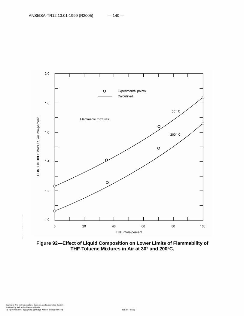
ANSI/ISA-TR12.13.01-1999 (R2005) — 140 —
Copyright The InstrumProvided by IHS underNo reproduction or net
--`,,```,,,,````-`-`,,`,,`,`,,`---
Figure 92—Effect of Liquid Composition on Lower Limits of Flammability of THF-Toluene Mixtures in Air at 30° and 200°C.
entation, Systems, and Automation Society license with ISA
Not for Resaleworking permitted without license from IHS
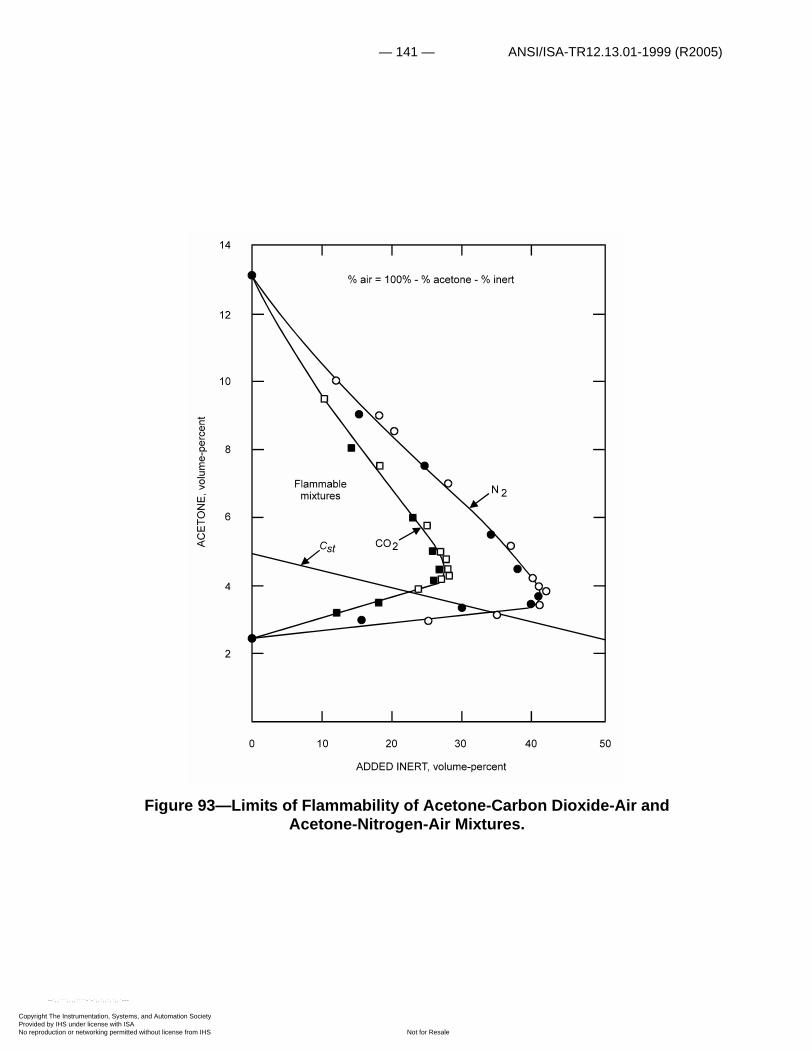
— 141 — ANSI/ISA-TR12.13.01-1999 (R2005)
Copyright The InstrumProvided by IHS underNo reproduction or net
--`,,```,,,,````
Figure 93—Limits of Flammability of Acetone-Carbon Dioxide-Air and Acetone-Nitrogen-Air Mixtures.
entation, Systems, and Automation Society license with ISA
Not for Resaleworking permitted without license from IHS
-`-`,,`,,`,`,,`---

ANSI/ISA-TR12.13.01-1999 (R2005) — 142 —
Copyright The InstrumProvided by IHS underNo reproduction or net
Table 18 — Properties of selected fuels and fuel blends
1Calculated value.2t = 150°C.3t = 100°C.
Combustible Formula M Sp gr (Air=1)
Cst in air (vol pct)
Net �Hc
Lower limit in air Upper limit in air
L25(vol pct)
Ref. U25(vol pct)
Ref.
Ammonia NH3 17.03 0.59 21.83 — 15 0.69 134 (167) 28 1.3 300 (182)
Hydrazine N2H4 32.05 1.11 17.32 — 4.7 .27 70 (188) 100 5.8 — (218)
Monomethylhydrazine N2H3CH3 46.07 1.59 7.73 — 4 .52 86 (218) — — — —
Unsymmetrical dimethylhydrazine
N2H2(CH3)2 60.10 2.08 4.97 — 2 .40 55 (166) 95 19.1 — (218)
Diborane B2H6 27.69 .96 6.53 478 .8 .12 10 (163) 88 13.5 — (163)
Tetraborane B4H10 53.36 1.84 3.67 — .4 .11 10 (1) — — — —
Pentaborane B5H9 63.17 2.18 3.37 1030 .42 .12 12 — — — — —
Decaborane B10H14 122.31 4.23 1.87 — .2 .11 11 (1) — — — —
Aviation gasoline100/130
— — — — — 1.3 — — (241) 7.1 — — (241)
Aviation gasoline 115/145
— — — — — 1.2 — — (241) 7.1 — — (241)
Aviation jet fuel JP-1 — — — — — — — 248 (241) — — 2380 (241)
Aviation jet fuel JP-3 — — — — — 1.4 — — (241) 8 — — (241)
Aviation jet fuel JP-4 — — — — — 1.3 — 48 (241) 8 — 330 (241)
Aviation jet fuel JP-6 — — — — — — — 346 (127) — — 2290 (127)
Hydrogen H2 2.016 .07 29.53 57.8 4.0 .14 3.7 (40) 75 2.54 270 (224)
Kcalmole------------- �
L25Cst--------- L mg
1-------� �� �
U25Cst---------- U mg
1-------� �� �
--`,,```,,,,````-`-`,,`,,`,`,,`---
entation, Systems, and Automation Society license with ISA
Not for Resaleworking permitted without license from IHS
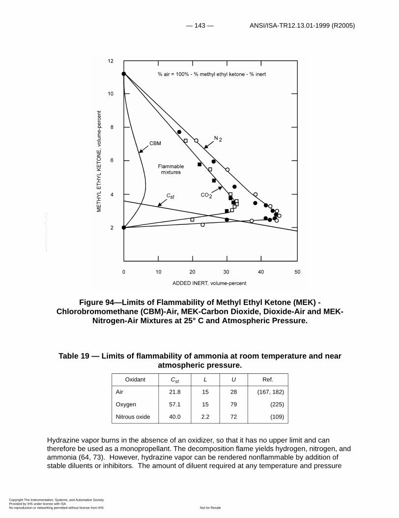
— 143 — ANSI/ISA-TR12.13.01-1999 (R2005)
Copyright The InstrumProvided by IHS underNo reproduction or net
Figure 94—Limits of Flammability of Methyl Ethyl Ketone (MEK) - Chlorobromomethane (CBM)-Air, MEK-Carbon Dioxide, Dioxide-Air and MEK-
Nitrogen-Air Mixtures at 25° C and Atmospheric Pressure.
Table 19 — Limits of flammability of ammonia at room temperature and near atmospheric pressure.
Hydrazine vapor burns in the absence of an oxidizer, so that it has no upper limit and can therefore be used as a monopropellant. The decomposition flame yields hydrogen, nitrogen, and ammonia (64, 73). However, hydrazine vapor can be rendered nonflammable by addition of stable diluents or inhibitors. The amount of diluent required at any temperature and pressure
Oxidant Cst L U Ref.
Air 21.8 15 28 (167, 182)
Oxygen 57.1 15 79 (225)
Nitrous oxide 40.0 2.2 72 (109)
--`,,```,,,,````-`-`,,`,,`,`,,`---
entation, Systems, and Automation Society license with ISA
Not for Resaleworking permitted without license from IHS

ANSI/ISA-TR12.13.01-1999 (R2005) — 144 —
Copyright The InstrumProvided by IHS underNo reproduction or net
--`,,```,,,,````-`-`,,`,,`,`,,`---
appears to be governed in part by the ignition source strength. With a 0.25-inch spark gap and a 15,000-volt, 60-ma-luminous-tube transformer as the energy source, Furno, Martindill, and Zabetakis (63) found that the following quantities of hydrocarbon vapor were needed to inhibit flame propagation in a 1 1/4-inch glass tube" at 125°C and atmospheric pressure: 39.8 pct benzene; 35.0 pct toluene; 27.3 pct m-xylene; 23.8 pct cumene; 21.0 pct n-heptane. On this same basis, 95.3 pct air is needed to revent flame propagation (188); this corresponds to a lower limit of flammability of 4.7 pct hydrazine vapor. The flammable range in air at atmospheric pressure is presented graphically in figure 98, which also gives the flammable ranges of monomethylhydrazine, unsymmetrical dimethylhydrazine, and ammonia for comparison (218). The flammability diagram for the system hydrazine-n-heptane-air at 125°C and atmospheric pressure is given in figure 99. These data were also obtained in a 1 1/4-inch glass tube.
A summary of the autoignition temperature data obtained by Perlee, Imhof, and Zabetakis (166) for hydrazine, MMH, and UDMH in air and nitrogen dioxide (actually, the equilibrium mixture
) is given in figure 100; short horizontal lines indicate the uncertainty in concentrations. These materials may ignite spontaneously at room temperature with
relatively small concentrations in the air; at 25°C, liquid UDMH ignites in NO2*-air
atmospheres that contain more than about 8 volume-percent ; MMH and hydrazine ignite in atmospheres that contain more than about 11 and 14 volume percent , respectively. In general, even smaller concentrations of produce spontaneous ignition of these combustibles at higher initial combustible liquid temperatures. The effect of the hydrazine liquid temperature on the spontaneous ignition temperature in -air atmospheres is illustrated in figure 101. Similar data are given in figures 102 and 103 for MMH and UDMH; there is an apparent anomaly in the data obtained with MMH at 36°, 55°, and 67°C.
"Comparable results were partially obtained in a 2-inch tube.
NO2* NO2 N2O4+�
NO2*
NO2*
NO2*
NO2*
NO2*
NO2*
entation, Systems, and Automation Society license with ISA
Not for Resaleworking permitted without license from IHS

— 145 — ANSI/ISA-TR12.13.01-1999 (R2005)
Copyright The InstrumProvided by IHS underNo reproduction or net
Figure 95—Limits of Flammability of Carbon Disulfide-Carbon Dioxide-Air, Carbon Dioxide-Nitrogen-Air Mixtures at 25°C and Atmospheric Pressure, and Carbon
Disulfide-Water Vapor-Air at 100°C and Atmospheric Pressure.
entation, Systems, and Automation Society license with ISA
Not for Resaleworking permitted without license from IHS
--`,,```,,,,````-`-`,,`,,`,`,,`---
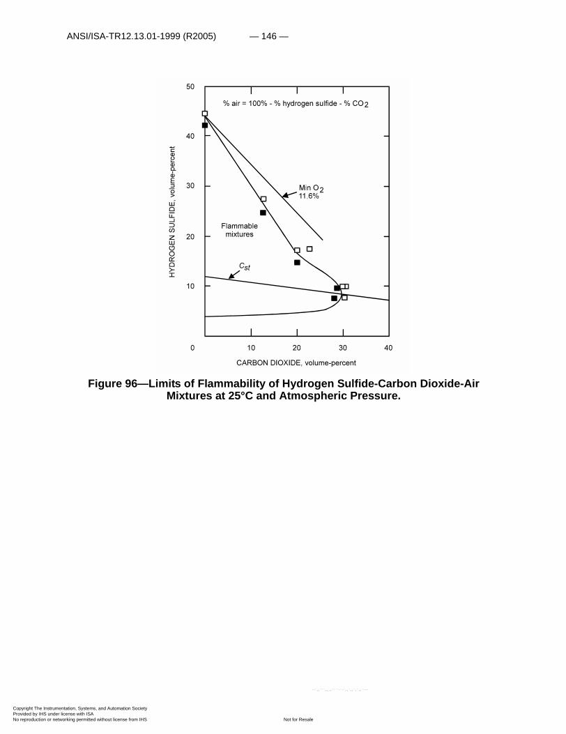
ANSI/ISA-TR12.13.01-1999 (R2005) — 146 —
Copyright The InstrumProvided by IHS underNo reproduction or net
Figure 96—Limits of Flammability of Hydrogen Sulfide-Carbon Dioxide-Air Mixtures at 25°C and Atmospheric Pressure.
entation, Systems, and Automation Society license with ISA
Not for Resaleworking permitted without license from IHS
--`,,```,,,,````-`-`,,`,,`,`,,`---

— 147 — ANSI/ISA-TR12.13.01-1999 (R2005)
Copyright The InstrumProvided by IHS underNo reproduction or net
Figure 97—Limits of Flammability of Ethyl Mercaptan-F-12-Air and Ethyl Mercaptan-F-22-Air Mixtures at Atmospheric Pressure and 27°C.
The use of various helium-oxygen atmospheres in place of air results in the spontaneous ignition temperature curves given in figure 104 for UDMH. Comparison of curve B of this set with curve A of figure 100 indicates that the spontaneous ignition temperature of UDMH in -He-O2 atmospheres is the same as that obtained in -air atmospheres.
Ignition temperature data obtained with UDMH in -air mixtures at 15 and 45 psia are summarized in figure 105. These indicate that although the spontaneous ignition temperature of UDMH in air is not affected appreciably by this pressure change, it is affected in a range of -air mixtures.
NO2*
NO2*
NO2*
NO2*
entation, Systems, and Automation Society license with ISA
Not for Resaleworking permitted without license from IHS
--`,,```,,,,````-`-`,,`,,`,`,,`---

ANSI/ISA-TR12.13.01-1999 (R2005) — 148 —
Copyright The InstrumProvided by IHS underNo reproduction or net
--`,,```,,,,````-`-`,,`,,`,`,,`---
Figure 98—Limits of Flammability of Ammonia, UDMH, MMH, and Hydrazine at Atmospheric Pressure in Saturated and Near-Saturated Vapor-Air Mixtures.
entation, Systems, and Automation Society license with ISA
Not for Resaleworking permitted without license from IHS
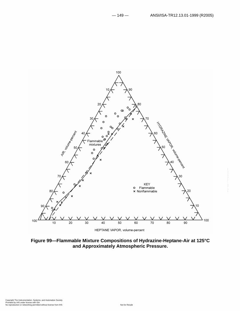
— 149 — ANSI/ISA-TR12.13.01-1999 (R2005)
Copyright The InstrumProvided by IHS underNo reproduction or net
--`,,```,,,,````-`-`,,`,,`,`,,`---
Figure 99—Flammable Mixture Compositions of Hydrazine-Heptane-Air at 125°C and Approximately Atmospheric Pressure.
entation, Systems, and Automation Society license with ISA
Not for Resaleworking permitted without license from IHS

ANSI/ISA-TR12.13.01-1999 (R2005) — 150 —
Copyright The InstrumProvided by IHS underNo reproduction or net
--`,,```,,,,````-`-`,,`,,`,`,,`---
Figure 100—Minimum Spontaneous Ignition Temperatures of Liquid Hydrazine, MMH, and UDMH at an Initial Temperature of 25°C in Contact With -Air
Mixtures at 740±10 mm Hg as a Function of Concentration.
The data presented in figures 100 to 105 were obtained with liquid fuel in contact with vaporized in air. Similar data obtained with vaporized UDMH-air in contact with are given in
figure 106. This figure indicates UDMH-air mixtures that contain more than 9 volume-percent UDMH will ignite spontaneously on contact with ; UDMH-air mixtures that contain more than approximately 2 volume-percent UDMH can be ignited by an ignition source under the same conditions (166).
NO2*
NO2*
NO2* NO2
*
NO2*
entation, Systems, and Automation Society license with ISA
Not for Resaleworking permitted without license from IHS
— 151 — ANSI/ISA-TR12.13.01-1999 (R2005)
Copyright The InstrumProvided by IHS underNo reproduction or net
--`,,```,,,,````-`-`,,`,,`,`,,`---
Boron Hydrides
This series includes diborane (B2H6), tetraborane (B4H10), pentaborane (B5H9), and decaborane (B10H14). However, reliable upper and lower limit data are available only on the first member of this series at the present time. These were obtained by Parker and Wolfhard (163) who determined the limits of flammability of diborane in air in a 5-cm-diameter tube at an initial pressure of 300 mm Hg; this combustible forms flammable mixtures in air in the range from 0.8 to 87.5 volume-percent. A pale blue flame propagated throughout the tube at the upper limit; luminous flames were not visible above 79 volume-percent. Limit of flammability curves for the system diborane-ethane-air are presented in rectangular coordinates in figure 107. Except for the slight dip to the ethane-axis (zero diborane) in the area in which ethane forms flammable mixtures in air, these curves are rather similar to those obtained with other combustible-oxidant-inert systems. Burning velocities in excess of 500 cm/sec were measured in this same study for fuel-rich diborane-air mixtures.
Berl and Renich have prepared a summary report about boron hydrides (9). It includes data obtained by these and other authors; they found the lower limit of pentaborane in air to be 0.42 volume-percent.
The autoignition temperature of diborane in air is apparently quite low. Price obtained a value of 135° C at 16.1 mm Hg (169); that of pentaborane is 30° C at about 8 mm Hg (9).
Gasolines, Diesel and Jet Fuels
Fuels considered in this section are blends that contain a wide variety of hydrocarbons and additives. Accordingly, their flammability characteristics are governed by the method used to extract a vapor sample as well as by the history of the liquid. For example, since the lower limit of flammability, expressed in volume-percent, is inversely proportional to the molecular weight of the combustible vapor, equation (28), the first vapors to come from a blend, such as gasoline, give a higher lower limit value than the completely vaporized sample. Conversely, the heavy fractions or residue give a smaller lower limit value. For this reason, there is some disagreement about the limits of flammability of blends such as gasoline and the diesel and jet fuels. These fuels are, in general, characterized by a wide distillation range; the ASTM distillation curves of two gasolines and three jet fuels considered here are given in figure 108. Unfortunately, such curves give only an approximate measure of the volatile constituents in the liquid blend.
Even relatively nonvolatile high-flashpoint oils may liberate flammable vapors at such a slow rate that the closed vapor space above the liquid may be made flammable at reduced temperatures. Gasolines can produce flammable saturated vapor-air mixture at temperatures below –65° C (241), although the flash points of such fuels are considered to be about –45° C (158). An apparent discrepancy thus exists if flashpoint data are used to predict the lowest temperature at which flammable mixtures can be formed in a closed vapor space above a blend in long-term storage.
As noted earlier, the limits of flammability of hydrocarbon fuels are not strongly dependent on molecular weight when the limits are expressed by weight. However, since results measured by a volume are perhaps more widely used than those measured by weight, typical flammability curves are presented by volume for the light fractions from aviation gasoline, grade 115/145 (fig. 109), and aviation jet fuel, grade JP-4 (fig. 110). Combustible vapor-air-carbon dioxide and vapor-air-nitrogen mixtures at about 25° C and atmospheric pressure are considered for each. Similar data are given in figure 14 for the gasoline vapor-air-water vapor system at 21° and 100°
entation, Systems, and Automation Society license with ISA
Not for Resaleworking permitted without license from IHS
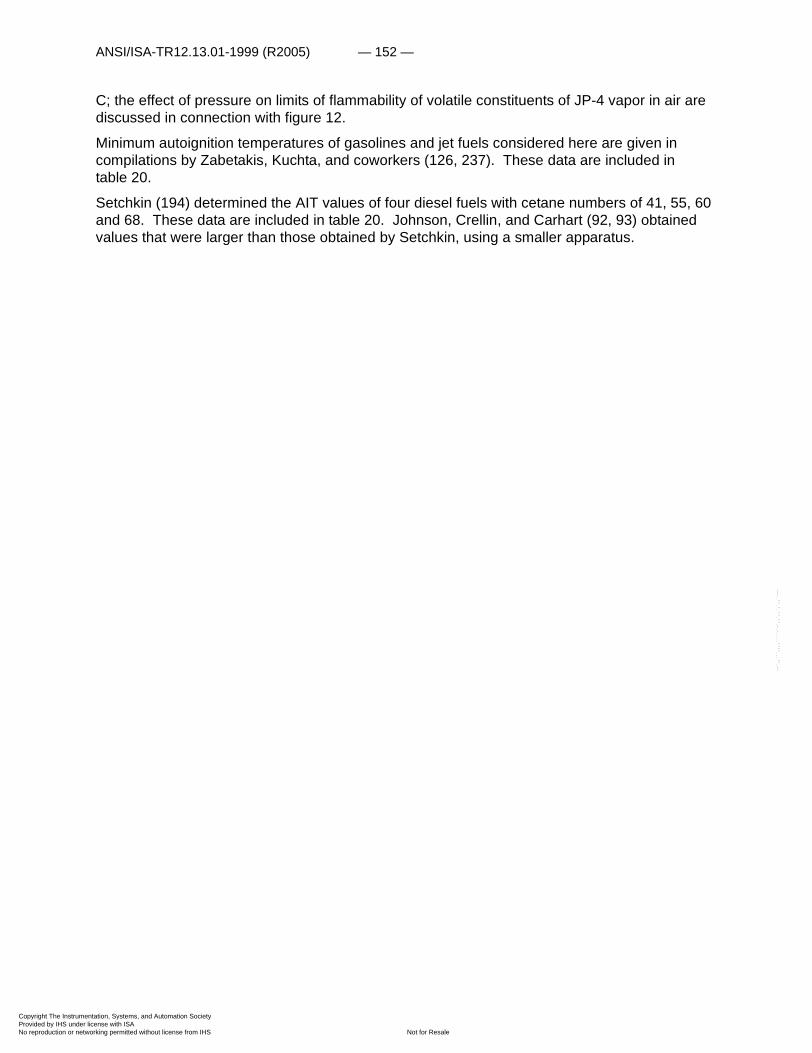
ANSI/ISA-TR12.13.01-1999 (R2005) — 152 —
Copyright The InstrumProvided by IHS underNo reproduction or net
--`,,```,,,,````-`-`,,`,,`,`,,`---
C; the effect of pressure on limits of flammability of volatile constituents of JP-4 vapor in air are discussed in connection with figure 12.
Minimum autoignition temperatures of gasolines and jet fuels considered here are given in compilations by Zabetakis, Kuchta, and coworkers (126, 237). These data are included in table 20.
Setchkin (194) determined the AIT values of four diesel fuels with cetane numbers of 41, 55, 60 and 68. These data are included in table 20. Johnson, Crellin, and Carhart (92, 93) obtained values that were larger than those obtained by Setchkin, using a smaller apparatus.
entation, Systems, and Automation Society license with ISA
Not for Resaleworking permitted without license from IHS
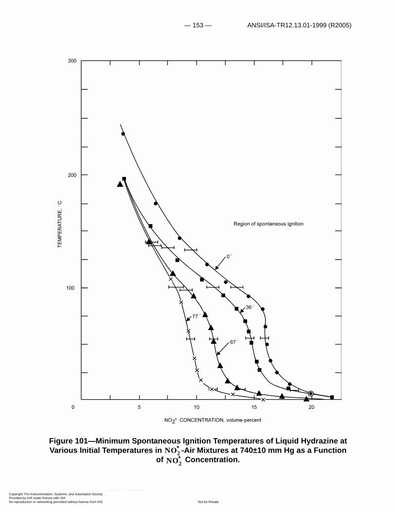
— 153 — ANSI/ISA-TR12.13.01-1999 (R2005)
Copyright The InstrumProvided by IHS underNo reproduction or net
Figure 101—Minimum Spontaneous Ignition Temperatures of Liquid Hydrazine at Various Initial Temperatures in -Air Mixtures at 740±10 mm Hg as a Function
of Concentration.NO2
*
NO2*
entation, Systems, and Automation Society license with ISA
Not for Resaleworking permitted without license from IHS
--`,,```,,,,````-`-`,,`,,`,`,,`---
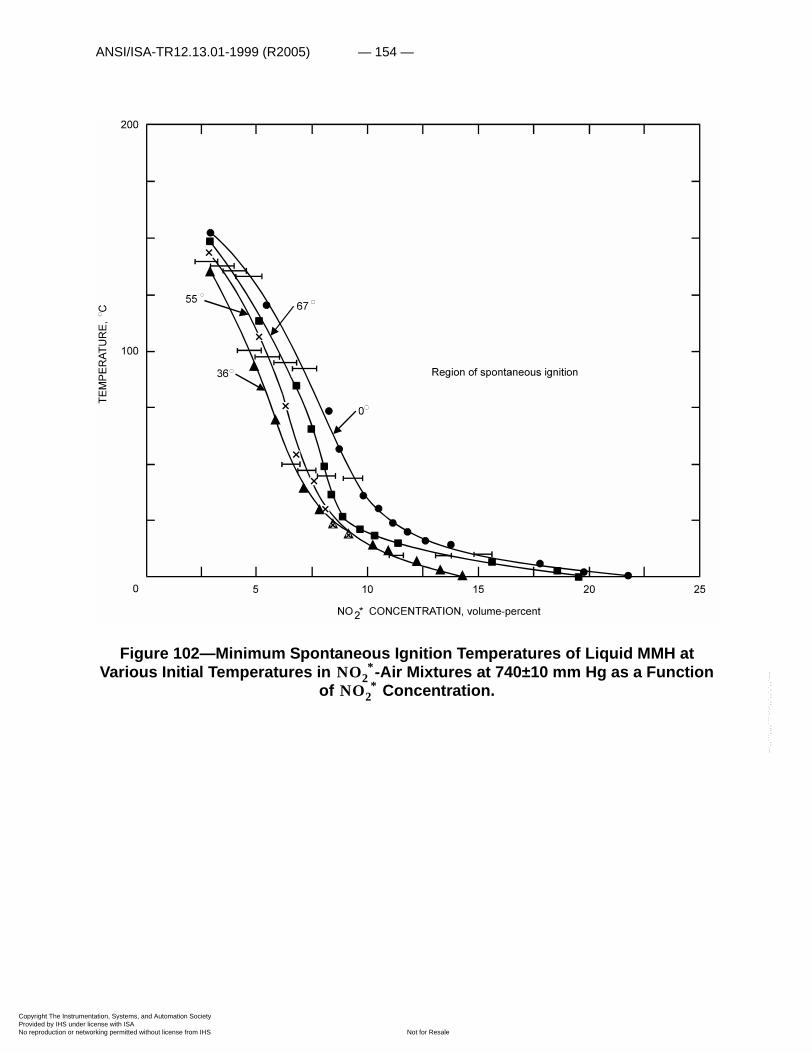
ANSI/ISA-TR12.13.01-1999 (R2005) — 154 —
Copyright The InstrumProvided by IHS underNo reproduction or net
--`,,```,,,,````-`-`,,`,,`,`,,`---
Figure 102—Minimum Spontaneous Ignition Temperatures of Liquid MMH at Various Initial Temperatures in -Air Mixtures at 740±10 mm Hg as a Function
of Concentration.NO2
*
NO2*
entation, Systems, and Automation Society license with ISA
Not for Resaleworking permitted without license from IHS
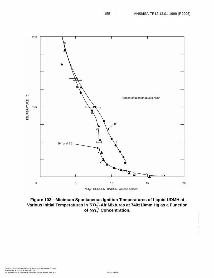
— 155 — ANSI/ISA-TR12.13.01-1999 (R2005)
Copyright The InstrumProvided by IHS underNo reproduction or net
--`,,```,,,,````-`-`,,`,,`,`,,`---
Figure 103—Minimum Spontaneous Ignition Temperatures of Liquid UDMH at Various Initial Temperatures in -Air Mixtures at 740±10mm Hg as a Function
of Concentration.NO2
*
NO2*
entation, Systems, and Automation Society license with ISA
Not for Resaleworking permitted without license from IHS

ANSI/ISA-TR12.13.01-1999 (R2005) — 156 —
Copyright The InstrumProvided by IHS underNo reproduction or net
--`,,```,,,,````-`-`,,`,,`,`,,`---
Figure 104—Minimum Spontaneous Ignition Temperatures of 0.05 cc of Liquid UDMH in He-O2- Atmospheres at 1 Atmosphere for Various He/O2 Ratios.NO2
*
entation, Systems, and Automation Society license with ISA
Not for Resaleworking permitted without license from IHS

— 157 — ANSI/ISA-TR12.13.01-1999 (R2005)
Copyright The InstrumProvided by IHS underNo reproduction or net
--`,,```,,,,````-`-`,,`,,`,`,,`---
Figure 105—Minimum Spontaneous Ignition Temperatures of 0.05 cc of Liquid UDMH in -Air Mixtures at 15 and 45 Psia as a Function of Concentration.NO2
* NO2*
entation, Systems, and Automation Society license with ISA
Not for Resaleworking permitted without license from IHS
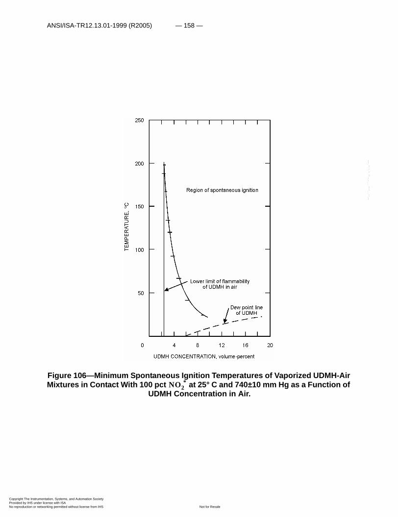
ANSI/ISA-TR12.13.01-1999 (R2005) — 158 —
Copyright The InstrumProvided by IHS underNo reproduction or net
--`,,```,,,,````-`-`,,`,,`,`,,`---
Figure 106—Minimum Spontaneous Ignition Temperatures of Vaporized UDMH-Air Mixtures in Contact With 100 pct at 25° C and 740±10 mm Hg as a Function of
UDMH Concentration in Air.NO2
*
entation, Systems, and Automation Society license with ISA
Not for Resaleworking permitted without license from IHS
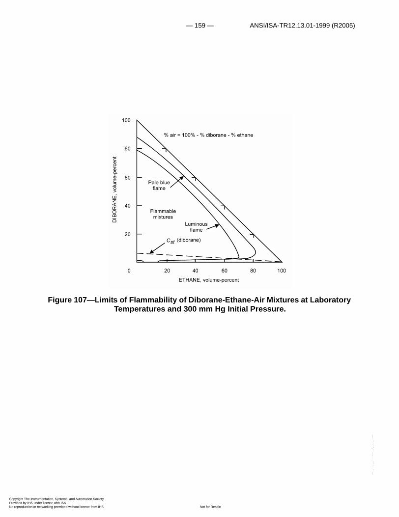
— 159 — ANSI/ISA-TR12.13.01-1999 (R2005)
Copyright The InstrumProvided by IHS underNo reproduction or net
--`,,```,,,,````-`-`,,`,,`,`,,`---
Figure 107—Limits of Flammability of Diborane-Ethane-Air Mixtures at Laboratory Temperatures and 300 mm Hg Initial Pressure.
entation, Systems, and Automation Society license with ISA
Not for Resaleworking permitted without license from IHS
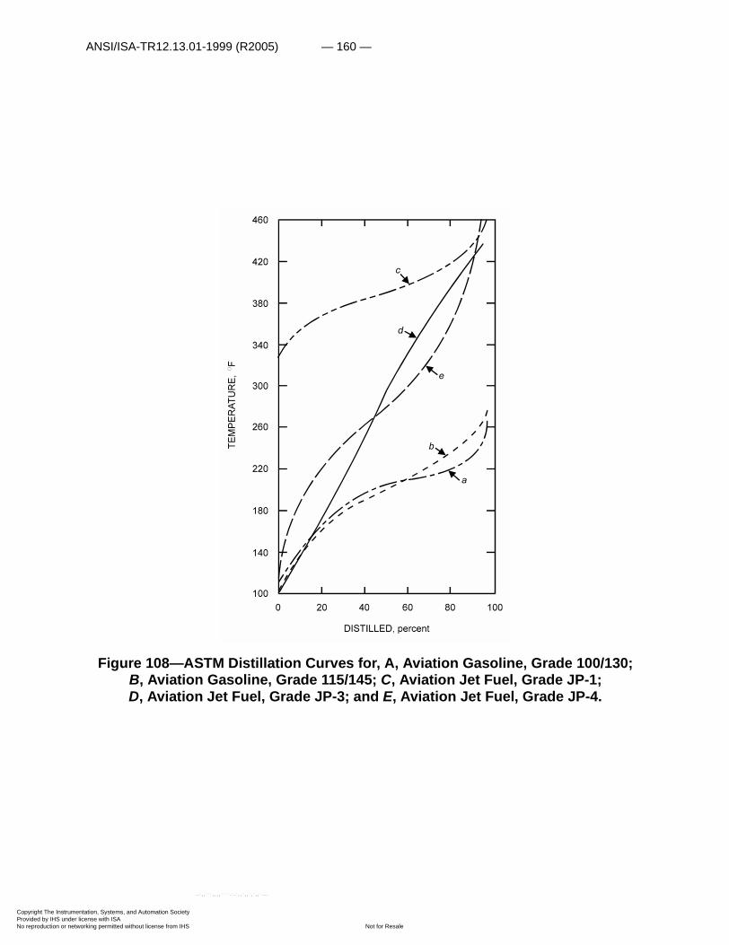
ANSI/ISA-TR12.13.01-1999 (R2005) — 160 —
Copyright The InstrumProvided by IHS underNo reproduction or net
Figure 108—ASTM Distillation Curves for, A, Aviation Gasoline, Grade 100/130; B, Aviation Gasoline, Grade 115/145; C, Aviation Jet Fuel, Grade JP-1; D, Aviation Jet Fuel, Grade JP-3; and E, Aviation Jet Fuel, Grade JP-4.
entation, Systems, and Automation Society license with ISA
Not for Resaleworking permitted without license from IHS
--`,,```,,,,````-`-`,,`,,`,`,,`---

— 161 — ANSI/ISA-TR12.13.01-1999 (R2005)
Copyright The InstrumProvided by IHS underNo reproduction or net
--`,,```,,,,````-`-`,,`,,`,`,,`---
Figure 109—Limits of Flammability of Aviation Gasoline, Grades 115/145 Vapor-Carbon Dioxide-Air and 115/145 Vapor-Nitrogen-Air, at 27°C and
Atmospheric Pressure.
entation, Systems, and Automation Society license with ISA
Not for Resaleworking permitted without license from IHS
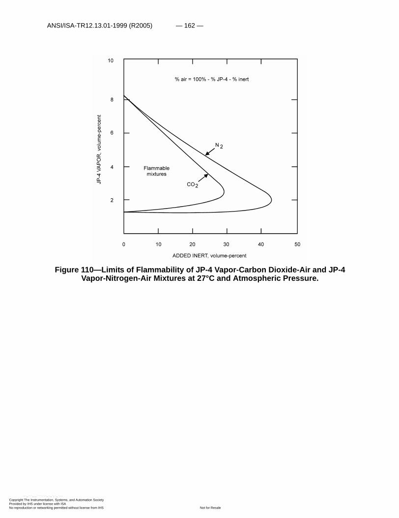
ANSI/ISA-TR12.13.01-1999 (R2005) — 162 —
Copyright The InstrumProvided by IHS underNo reproduction or net
--`,,```,,,,````
Figure 110—Limits of Flammability of JP-4 Vapor-Carbon Dioxide-Air and JP-4 Vapor-Nitrogen-Air Mixtures at 27°C and Atmospheric Pressure.
entation, Systems, and Automation Society license with ISA
Not for Resaleworking permitted without license from IHS
-`-`,,`,,`,`,,`---

— 163 — ANSI/ISA-TR12.13.01-1999 (R2005)
Copyright The InstrumProvided by IHS underNo reproduction or net
--`,,```,,,,````-`-`,,`,,`,`,,`---
Table 20 — Autoignition temperature values of various fuels in air at 1 atmosphere
Burning velocities of the fuels considered here are in the same range as those of the hydrocarbons considered earlier. Values for various fuels have been tabulated by Barnett and Hibbard (156).
Hydrogen
Numerous flammability characteristics studies have been conducted with hydrogen in recent years. Drell and Belles have prepared an excellent survey of these characteristics (48). This survey includes all but the most recent work of interest.
The low pressure limits of flame propagation for stoichiometric hydrogen-air mixtures are somewhat lower than those for stoichiometric ethylene-air mixtures (197) in cylindrical tubes. In the range from 6 to 130 mm Hg, the limit for stoichiometric hydrogen-air mixtures is given by the expression:
log P=3.19–1.19 log D, (57)
where P is the low-pressure limit in millimeters of Hg, and D is the tube diameter in millimeters.
Hydrogen forms flammable mixtures at ambient temperatures and pressures with oxygen, air, chlorine, and the oxides of nitrogen. Limits of flammability in these oxidants at approximately 25°C and 1 atmosphere are listed in table 21.
Flammability diagrams of the systems hydrogen-air-carbon dioxide and hydrogen-air-nitrogen obtained by Jones and Perrott (112) are given in figure 111. Lines that establish minimum oxygen values for each system are also included. Note that although the minimum value occurs
Fuel: AIT, °C
Aviation gasoline:
100/130 440
115/145 471
Aviation jet fuel:
JP-1 228
JP-3 238
JP-4 242
JP-6 232
Diesel fuel:
41 cetane 233
55 cetane 230
60 cetane 225
68 cetane 226
entation, Systems, and Automation Society license with ISA
Not for Resaleworking permitted without license from IHS
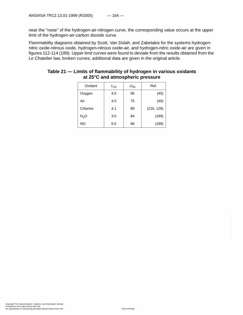
ANSI/ISA-TR12.13.01-1999 (R2005) — 164 —
Copyright The InstrumProvided by IHS underNo reproduction or net
--`,,```,,,,````-`-`,,`,,`,`,,`---
near the "nose" of the hydrogen-air-nitrogen curve, the corresponding value occurs at the upper limit of the hydrogen-air-carbon dioxide curve.
Flammability diagrams obtained by Scott, Van Dolah, and Zabetakis for the systems hydrogen-nitric oxide-nitrous oxide, hydrogen-nitrous oxide-air, and hydrogen-nitric oxide-air are given in figures 112-114 (189). Upper limit curves were found to deviate from the results obtained from the Le Chatelier law, broken curves; additional data are given in the original article.
Table 21 — Limits of flammability of hydrogen in various oxidants at 25°C and atmospheric pressure
Oxidant L25 U25 Ref.
Oxygen 4.0 95 (40)
Air 4.0 75 (40)
Chlorine 4.1 89 (216, 128)
N2O 3.0 84 (189)
NO 6.6 66 (189)
entation, Systems, and Automation Society license with ISA
Not for Resaleworking permitted without license from IHS
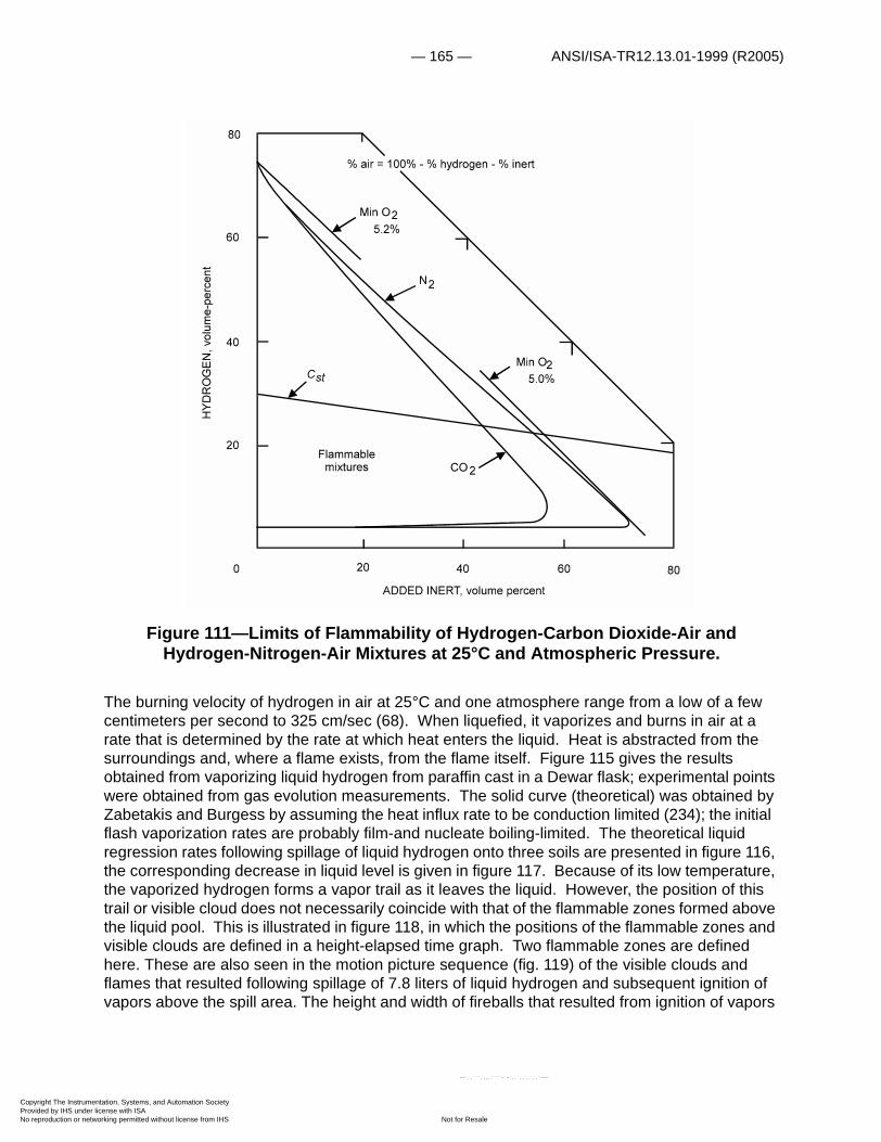
— 165 — ANSI/ISA-TR12.13.01-1999 (R2005)
Copyright The InstrumProvided by IHS underNo reproduction or net
Figure 111—Limits of Flammability of Hydrogen-Carbon Dioxide-Air and Hydrogen-Nitrogen-Air Mixtures at 25°C and Atmospheric Pressure.
The burning velocity of hydrogen in air at 25°C and one atmosphere range from a low of a few centimeters per second to 325 cm/sec (68). When liquefied, it vaporizes and burns in air at a rate that is determined by the rate at which heat enters the liquid. Heat is abstracted from the surroundings and, where a flame exists, from the flame itself. Figure 115 gives the results obtained from vaporizing liquid hydrogen from paraffin cast in a Dewar flask; experimental points were obtained from gas evolution measurements. The solid curve (theoretical) was obtained by Zabetakis and Burgess by assuming the heat influx rate to be conduction limited (234); the initial flash vaporization rates are probably film-and nucleate boiling-limited. The theoretical liquid regression rates following spillage of liquid hydrogen onto three soils are presented in figure 116, the corresponding decrease in liquid level is given in figure 117. Because of its low temperature, the vaporized hydrogen forms a vapor trail as it leaves the liquid. However, the position of this trail or visible cloud does not necessarily coincide with that of the flammable zones formed above the liquid pool. This is illustrated in figure 118, in which the positions of the flammable zones and visible clouds are defined in a height-elapsed time graph. Two flammable zones are defined here. These are also seen in the motion picture sequence (fig. 119) of the visible clouds and flames that resulted following spillage of 7.8 liters of liquid hydrogen and subsequent ignition of vapors above the spill area. The height and width of fireballs that resulted from ignition of vapors
entation, Systems, and Automation Society license with ISA
Not for Resaleworking permitted without license from IHS
--`,,```,,,,````-`-`,,`,,`,`,,`---
ANSI/ISA-TR12.13.01-1999 (R2005) — 166 —
Copyright The InstrumProvided by IHS underNo reproduction or net
--`,,```,,,,````-`-`,,`,,`,`,,`---
produced by rapid vaporization of about 3 to 90 liters of liquid hydrogen are given in figure 120. The data are represented fairly well by the equation
, (58)
where Hmax and Wmax are the maximum flame height and width, respectively, V1 is the volume of liquid hydrogen in liters, and M is the mass of this volume in pounds.
The burning rate of a 6-inch pool of liquid hydrogen in air is given as the regression of the liquid level in figure 121; burning rate data for liquid methane are included for comparison. An extrapolated value of burning rate for large pools of liquid hydrogen is included in figure 52.
Approximate quantity-distance relationships can be established for the storage of liquid hydrogen near inhabited buildings and other storage sites if certain assumptions are made (33, 160, 234). Additional work is required to establish such distances for very large quantities of liquid.
The detonation velocity and the static and reflected pressures developed by a detonation wave propagating through hydrogen-oxygen mixtures are given in figure 16. The predetonation distance in horizontal pipes is reportedly proportional to the square root of the pipe diameter (229); this is presumably applicable to results obtained with a mild ignition source, since a shock front can establish a detonation at essentially zero runup distance. Numerous investigators have examined this and related problems in recent years (11-13, 65, 135-137, 151).
Hmax Wmax 7 V1feet 17.8 M feet== =
entation, Systems, and Automation Society license with ISA
Not for Resaleworking permitted without license from IHS
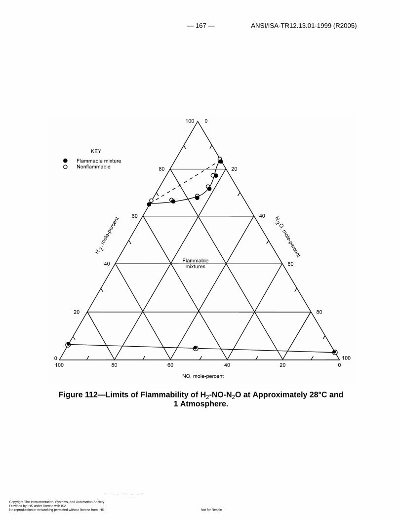
— 167 — ANSI/ISA-TR12.13.01-1999 (R2005)
Copyright The InstrumProvided by IHS underNo reproduction or net
Figure 112—Limits of Flammability of H2-NO-N2O at Approximately 28°C and 1 Atmosphere.
entation, Systems, and Automation Society license with ISA
Not for Resaleworking permitted without license from IHS
--`,,```,,,,````-`-`,,`,,`,`,,`---

ANSI/ISA-TR12.13.01-1999 (R2005) — 168 —
Copyright The InstrumProvided by IHS underNo reproduction or net
--`,,```,,,,````-`-`,,`,,`,`,,`---
Figure 113—Limits of Flammability of H2-N2O-Air at Approximately 28°C and 1 Atmosphere.
entation, Systems, and Automation Society license with ISA
Not for Resaleworking permitted without license from IHS
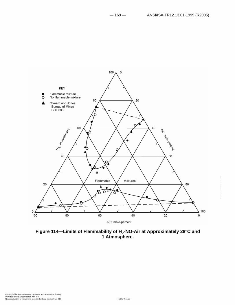
— 169 — ANSI/ISA-TR12.13.01-1999 (R2005)
Copyright The InstrumProvided by IHS underNo reproduction or net
--`,,```,,,,````-`-`,,`,,`,`,,`---
Figure 114—Limits of Flammability of H2-NO-Air at Approximately 28°C and 1 Atmosphere.
entation, Systems, and Automation Society license with ISA
Not for Resaleworking permitted without license from IHS
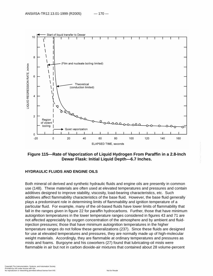
ANSI/ISA-TR12.13.01-1999 (R2005) — 170 —
Copyright The InstrumProvided by IHS underNo reproduction or net
--`,,```,,,,````-`-`,,`,,`,`,,`---
Figure 115—Rate of Vaporization of Liquid Hydrogen From Paraffin in a 2.8-Inch Dewar Flask: Initial Liquid Depth—6.7 Inches.
HYDRAULIC FLUIDS AND ENGINE OILS
Both mineral oil derived and synthetic hydraulic fluids and engine oils are presently in common use (148). These materials are often used at elevated temperatures and pressures and contain additives designed to improve stability, viscosity, load-bearing characteristics, etc. Such additives affect flammability characteristics of the base fluid. However, the base fluid generally plays a predominant role in determining limits of flammability and ignition temperature of a particular fluid. For example, many of the oil-based fluids have lower limits of flammability that fall in the ranges given in figure 22 for paraffin hydrocarbons. Further, those that have minimum autoignition temperatures in the lower temperature ranges considered in figures 43 and 71 are not affected appreciably by oxygen concentration of the atmosphere and by ambient and fluid-injection pressures; those that have minimum autoignition temperatures in the higher temperature ranges do not follow these generalizations (237). Since these fluids are designed for use at elevated temperatures and pressures, they are normally made up of high-molecular weight materials. Accordingly, they are flammable at ordinary temperatures and pressures as mists and foams. Burgoyne and his coworkers (27) found that lubricating-oil mists were flammable in air but not in carbon dioxide-air mixtures that contained about 28 volume-percent
entation, Systems, and Automation Society license with ISA
Not for Resaleworking permitted without license from IHS

— 171 — ANSI/ISA-TR12.13.01-1999 (R2005)
Copyright The InstrumProvided by IHS underNo reproduction or net
carbon dioxide (fig. 35). At elevated temperatures, the oil vapors cracked and produced acetylene and hydrogen, which affected the flammability of the resultant mixture; the vapors are often unstable at elevated temperatures. Chiantella, Affens, and Johnson have determined the effect of elevated temperatures on the stability and ignition properties of three commercial triaryl phosphate fluids (36).
Zabetakis, Scott, and Kennedy have determined the effect of pressure on the autoignition temperatures of commercial lubricants (248). Figure 122 gives the minimum autoignition temperatures for four commercial phosphate ester-base fluids (curves 1-4) and three mineral oils (curves 5-7). In each case, the minimum autoignition temperature was found to decrease with increase in pressure over most of the pressure range considered. A plot of the logarithm of the initial pressure to temperature ratio versus the reciprocal of the temperature is given for curves 1 to 7 in figure 123. The resultant curves are linear over a limited temperature range.
Figure 116—Theoretical Liquid Regression Rates Following Spillage of Liquid Hydrogen Onto, A, an Average Soil; B, Moist Sandy Soil (8 Pct. Moisture); and
C, Dry Sandy Soil.
entation, Systems, and Automation Society license with ISA
Not for Resaleworking permitted without license from IHS
--`,,```,,,,````-`-`,,`,,`,`,,`---

ANSI/ISA-TR12.13.01-1999 (R2005) — 172 —
Copyright The InstrumProvided by IHS underNo reproduction or net
--`,,```,,,,````-`-`,,`,,`,`,,`---
Figure 117—Theoretical Decrease in Liquid Hydrogen Level Following Spillage Onto, A, Dry Sandy Soil; B, Moist Sandy Soil (8 Pct. Moisture); and C, Average Soil.
Figure 118—Extent of Flammable Mixtures and Height of Visible Cloud Formed After Rapid Spillage of 3 Liters of Liquid Hydrogen on a Dry Macadam Surface in a
Quiescent Air Atmosphere at 15°C.
entation, Systems, and Automation Society license with ISA
Not for Resaleworking permitted without license from IHS

— 173 — ANSI/ISA-TR12.13.01-1999 (R2005)
Copyright The InstrumProvided by IHS underNo reproduction or net
Figure 119—Motion Picture Sequence (16 Frames per Second) of Visible Clouds and Flames Resulting From Rapid Spillage of 7.8 Liters of Liquid Hydrogen on a
Gravel Surface at 18°C. Ignition Source: 20 Inches Above Gravel.
--`,,```,,,,````-`-`,,`,,`,`,,`---
entation, Systems, and Automation Society license with ISA
Not for Resaleworking permitted without license from IHS

ANSI/ISA-TR12.13.01-1999 (R2005) — 174 —
Copyright The InstrumProvided by IHS underNo reproduction or net
Figure 120—Maximum Flame Height and Width Produced by Ignition of Vapor-Air Mixtures Formed by Sudden Spillage of 2.8 to 89 Liters of Liquid Hydrogen (V1).
Figure 121—Burning Rates of Liquid Hydrogen and of Liquid Methane at the Boiling Points in 6-Inch-Pyrex Dewar Flasks.
entation, Systems, and Automation Society license with ISA
Not for Resaleworking permitted without license from IHS
--`,,```,,,,````-`-`,,`,,`,`,,`---

— 175 — ANSI/ISA-TR12.13.01-1999 (R2005)
Copyright The InstrumProvided by IHS underNo reproduction or net
--`,,```,,,,````-`-`,,`,,`,`,,`---
The ratio of the final temperature attained by air in an adiabatic compression process to the initial temperature is given in figure 124 as a function of both the final-to-initial pressure ratio and initial-to-final volume ratio. If a lubricating oil is exposed to high temperatures during a compression process, autoignition may occur if the residence or contact time is adequate. Such high temperatures do occur in practice and have been known to cause disastrous explosions (58, 146, 149, 227, 231). The curves in figure 125 show that in the compression pressure range 1 to 10 atmospheres (initial pressure=1 atmosphere), a wide range of ambient temperatures can lead to the autoignition of a mineral oil lubricant (curve 5) if sufficient vapor or mist is in the system. In the same pressure range, only elevated initial temperatures could lead to the autoignition of a phosphate ester (curve 4). If the initial pressure is increased to 10 atmospheres, autoignition can occur at lower air-intake temperatures in every case (248).
MISCELLANEOUS
The flammability characteristics of a number of miscellaneous combustibles not considered elsewhere, are discussed in this section. These include carbon monoxide, n-propyl nitrate, and the halogenated hydrocarbons. The properties of these and a great variety of other materials are included in Appendix A.
The limits of flammability of the systems carbon monoxide-carbon dioxide-air and carbon monoxide-nitrogen-air are presented in figure 126. These curves were constructed from the flammability data obtained by Jones in a 2-inch vertical glass tube with upward flame propagation (112); other representations may be found in the original reference and in the compilation prepared by Coward and Jones (40).
Materials that are oxidized or decomposed readily may yield erratic flammability data under certain conditions. This effect is illustrated in figure 127 which summarizes the lower-limits data obtained by Zabetakis, Mason and Van Dolah with n-propyl nitrate (NPN) in air at various temperatures and pressures (243). An increase in temperature from 75° to 125°C is accompanied by a decrease in the lower-limit values; a further increase in temperature to 150°C results in a further lowering of the lower limit at pressures below 100 psig, but not at the higher pressures. An increase in the temperature to 170°C results in an apparent increase in the lower-limit value because of the slow oxidation of NPN. A complete flammability diagram has been constructed for the NPN vapor system in figure 128; a single lower limit curve and two upper limit curves are given here to show the effect of pressure on the flammable range of a vapor-air system.
The spontaneous ignition of NPN in air was considered earlier at 1,000 psig, (figs. 3, 4). The explosion pressures obtained at this initial pressure in air and in a 10-volume-percent oxygen +90-volume-percent nitrogen atmosphere at various NPN concentrations are presented in figure 129. A summary of the minimum spontaneous ignition and decomposition temperatures obtained with NPN in air and nitrogen respectively are given in figure 130. The data given in this figure exhibit a behavior that is typical of that found with other combustibles at elevated pressures; the minimum spontaneous ignition temperature first decreases with initial increase in pressure and then increases as the pressure is increased still further (120, 248).
entation, Systems, and Automation Society license with ISA
Not for Resaleworking permitted without license from IHS
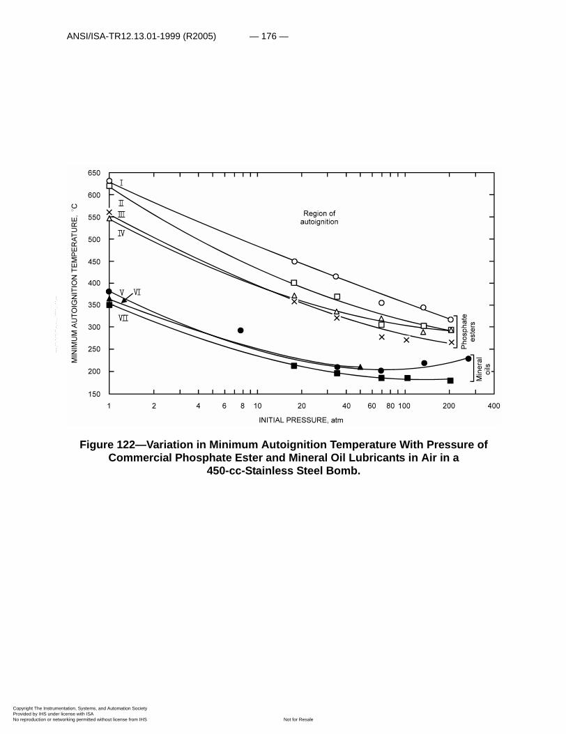
ANSI/ISA-TR12.13.01-1999 (R2005) — 176 —
Copyright The InstrumProvided by IHS underNo reproduction or net
--`,,```,,,,````-`-`,,`,,`,`,,`---
Figure 122—Variation in Minimum Autoignition Temperature With Pressure of Commercial Phosphate Ester and Mineral Oil Lubricants in Air in a
450-cc-Stainless Steel Bomb.
entation, Systems, and Automation Society license with ISA
Not for Resaleworking permitted without license from IHS

— 177 — ANSI/ISA-TR12.13.01-1999 (R2005)
Copyright The InstrumProvided by IHS underNo reproduction or net
Figure 123—Logarithm of Initial Pressure-AIT Ratio of Seven Fluids in Air for Various Reciprocal Temperatures. Data from Figure 122.
--`,,```,,,,````-`-`,,`,,`,`,,`---
entation, Systems, and Automation Society license with ISA
Not for Resaleworking permitted without license from IHS

ANSI/ISA-TR12.13.01-1999 (R2005) — 178 —
Copyright The InstrumProvided by IHS underNo reproduction or net
--`,,```,,,,````-`-`,,`,,`,`,,`---
Figure 124—Variation in Tf /Ti of Air With Vi /Vf and With Pf /Pi in an Adiabatic Compression Process.
entation, Systems, and Automation Society license with ISA
Not for Resaleworking permitted without license from IHS

— 179 — ANSI/ISA-TR12.13.01-1999 (R2005)
Copyright The InstrumProvided by IHS underNo reproduction or net
--`,,```,,,,````-`-`,,`,,`,`,,`---
Figure 125—Variation In Air Temperature With Pf /Pi in an Adiabatic Compression Process for Five Initial Air Temperatures (0°, 25°, 50°, 75°, and 100°C). Regions of autoignition for lubricants IV and V at Pf /Pi Between 1 and 10 Atmospheres and
Pi of Between 1 and 10 Atmospheres.
entation, Systems, and Automation Society license with ISA
Not for Resaleworking permitted without license from IHS
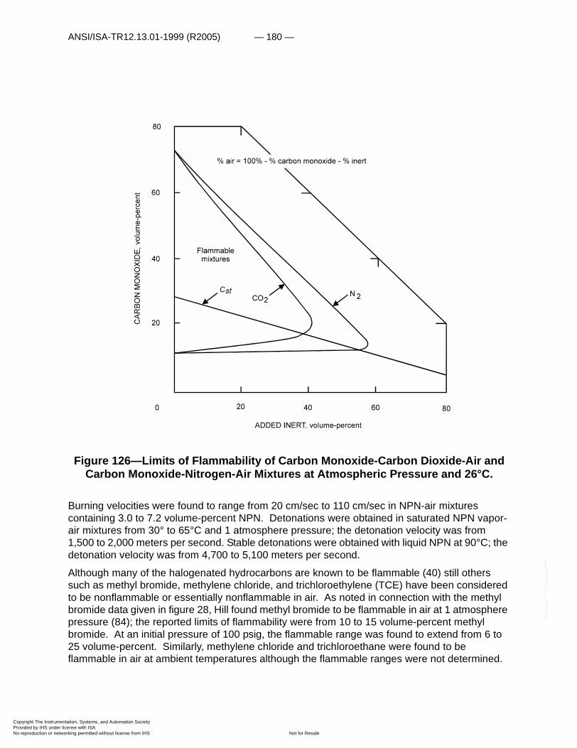
ANSI/ISA-TR12.13.01-1999 (R2005) — 180 —
Copyright The InstrumProvided by IHS underNo reproduction or net
--`,,```,,,,````-`-`,,`,,`,`,,`---
Figure 126—Limits of Flammability of Carbon Monoxide-Carbon Dioxide-Air and Carbon Monoxide-Nitrogen-Air Mixtures at Atmospheric Pressure and 26°C.
Burning velocities were found to range from 20 cm/sec to 110 cm/sec in NPN-air mixtures containing 3.0 to 7.2 volume-percent NPN. Detonations were obtained in saturated NPN vapor-air mixtures from 30° to 65°C and 1 atmosphere pressure; the detonation velocity was from 1,500 to 2,000 meters per second. Stable detonations were obtained with liquid NPN at 90°C; the detonation velocity was from 4,700 to 5,100 meters per second.
Although many of the halogenated hydrocarbons are known to be flammable (40) still others such as methyl bromide, methylene chloride, and trichloroethylene (TCE) have been considered to be nonflammable or essentially nonflammable in air. As noted in connection with the methyl bromide data given in figure 28, Hill found methyl bromide to be flammable in air at 1 atmosphere pressure (84); the reported limits of flammability were from 10 to 15 volume-percent methyl bromide. At an initial pressure of 100 psig, the flammable range was found to extend from 6 to 25 volume-percent. Similarly, methylene chloride and trichloroethane were found to be flammable in air at ambient temperatures although the flammable ranges were not determined.
entation, Systems, and Automation Society license with ISA
Not for Resaleworking permitted without license from IHS
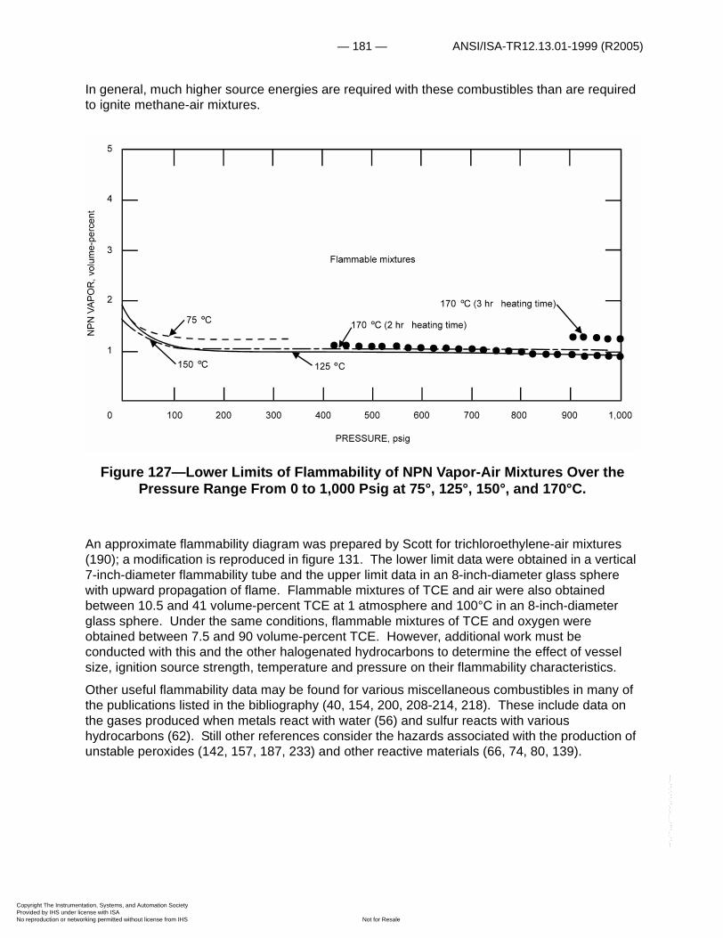
— 181 — ANSI/ISA-TR12.13.01-1999 (R2005)
Copyright The InstrumProvided by IHS underNo reproduction or net
--`,,```,,,,````-`-`,,`,,`,`,,`---
In general, much higher source energies are required with these combustibles than are required to ignite methane-air mixtures.
Figure 127—Lower Limits of Flammability of NPN Vapor-Air Mixtures Over the Pressure Range From 0 to 1,000 Psig at 75°, 125°, 150°, and 170°C.
An approximate flammability diagram was prepared by Scott for trichloroethylene-air mixtures (190); a modification is reproduced in figure 131. The lower limit data were obtained in a vertical 7-inch-diameter flammability tube and the upper limit data in an 8-inch-diameter glass sphere with upward propagation of flame. Flammable mixtures of TCE and air were also obtained between 10.5 and 41 volume-percent TCE at 1 atmosphere and 100°C in an 8-inch-diameter glass sphere. Under the same conditions, flammable mixtures of TCE and oxygen were obtained between 7.5 and 90 volume-percent TCE. However, additional work must be conducted with this and the other halogenated hydrocarbons to determine the effect of vessel size, ignition source strength, temperature and pressure on their flammability characteristics.
Other useful flammability data may be found for various miscellaneous combustibles in many of the publications listed in the bibliography (40, 154, 200, 208-214, 218). These include data on the gases produced when metals react with water (56) and sulfur reacts with various hydrocarbons (62). Still other references consider the hazards associated with the production of unstable peroxides (142, 157, 187, 233) and other reactive materials (66, 74, 80, 139).
entation, Systems, and Automation Society license with ISA
Not for Resaleworking permitted without license from IHS
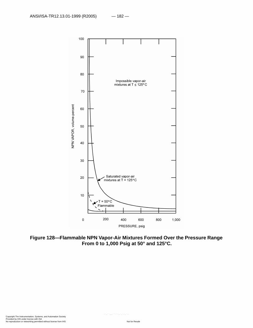
ANSI/ISA-TR12.13.01-1999 (R2005) — 182 —
Copyright The InstrumProvided by IHS underNo reproduction or net
Figure 128—Flammable NPN Vapor-Air Mixtures Formed Over the Pressure Range From 0 to 1,000 Psig at 50° and 125°C.
entation, Systems, and Automation Society license with ISA
Not for Resaleworking permitted without license from IHS
--`,,```,,,,````-`-`,,`,,`,`,,`---

— 183 — ANSI/ISA-TR12.13.01-1999 (R2005)
Copyright The InstrumProvided by IHS underNo reproduction or net
Figure 129—Variation of Explosion Pressure Following Spontaneous Ignition With NPN Concentration, Initial Pressure 1,000 Psig.
Figure 130—Minimum Spontaneous Ignition and Decomposition Temperatures of n-Propyl Nitrate in Air as a Function of Pressure, Type 347 Stainless Steel
Test Chamber.
entation, Systems, and Automation Society license with ISA
Not for Resaleworking permitted without license from IHS
--`,,```,,,,````-`-`,,`,,`,`,,`---
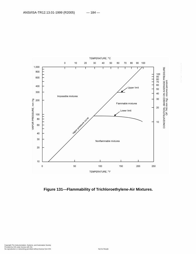
ANSI/ISA-TR12.13.01-1999 (R2005) — 184 —
Copyright The InstrumProvided by IHS underNo reproduction or net
--`,,```,,,,````-`-`,,`,,`,`,,`---
Figure 131—Flammability of Trichloroethylene-Air Mixtures.
entation, Systems, and Automation Society license with ISA
Not for Resaleworking permitted without license from IHS

— 185 — ANSI/ISA-TR12.13.01-1999 (R2005)
Copyright The InstrumProvided by IHS underNo reproduction or net
--`,,```,,,,````-`-`,,`,,`,`,,`---
Acknowledgments
Many of the unpublished data reported here were obtained by the predecessor of the author, the late G. W. Jones, former chief of the gas explosions branch. Other data were obtained by the author and his coworkers, particularly Messrs. George S. Scott, Joseph M. Kuchta, Aldo L. Furno and Henry E. Perlee. In addition, the author is indebted to Drs. David Burgess" and Robert W. Van Dolah for many fruitful discussions of the material contained in the sections on Definitions and Theory, Deflagration and Detonation Processes, and Preventive Measures.
"Presently with Reaction Motors Division, Thiokol Chemical Corporation, Denville, New Jersey.
entation, Systems, and Automation Society license with ISA
Not for Resaleworking permitted without license from IHS

ANSI/ISA-TR12.13.01-1999 (R2005) — 186 —
Copyright The InstrumProvided by IHS underNo reproduction or net
,````-`-`,,`,,`,`,,`---
Bibliography
1) Affens, W. A., J. E. Johnson, and H. W. Carhart. Effect of Chemical Structure on Spontaneous Ignition of Hydrocarbons. J. Chem. Eng. Data, v. 6, 1961, pp. 613-619.
2) _____. Ignition Studies, Part V, Study of the Processes Occurring During the Spontaneous Ignition of the Hexane Isomers. NRL Rept. 5437, January 1960, 15 pp.
3) Agnew, J. T., and L. B. Graiff. The Pressure Dependence of Laminar Burning Velocity by the Spherical Bomb Method. Combustion and Flame, v. 5, 1961, pp. 209-219.
4) Alexander, D. S. Explosions in Butadiene Systems. Ind. and Eng. Chem., v. 51, 1959, pp. 733-738.
5) Anson, D. Influence of the Quality of Atomization on the Stability of Combustion of Liquid Fuel Sprays. Fuel, v. 32, 1953, pp. 39-51.
6) Ashman, L. E., and A. Büchler. The Ignition of Gases by Electrically Heated Wires. Combustion and Flame, v. 5, 1961, pp. 113-121.
7) Bartkowiak, Alphonse, Sotirios Lambiris, and Michael G. Zabetakis. Flame Propagation Through Kerosine Foams. Combustion and Flame, v. 3, 1959, pp. 347-353.
8) Bartkowiak, Alphonse, and Michael G. Zabetakis. Flammability Limits of Methane and Ethane in Chlorine at Ambient and Elevated Temperatures and Pressure. BuMines Rept. of Inv. 5610, 1960, 6 pp.
9) Berl, W. G. and W. Renich. The Combustion of Boron Hydrides. CM-942, Johns Hopkins Univ., Silver Spring, Md., 1958, 53 pp.
10) Block, Benjamin. Emergency Venting for Tanks and Reactors. Chem. Eng., January 1962, pp. 111-118.
11) Bollinger, Loren E., and Rudolph Edse. Thermodynamic Calculations of Hydrogen-Oxygen Detonation Parameters for Various Initial Pressures. ARS J., v. 31, 1961, pp. 251-256.
12) Bollinger, Loren E., Michael G. Fong, and Rudolph Edse. Experimental Measurements and Theoretical Analysis of Detonation Induction Distances. ARS J., 1961, pp. 588-594.
13) Bollinger, Loren E., James A. Laughrey, and Rudolph Edse. Experimental Detonation Velocities and Induction Distances in Hydrogen-Nitrous Oxide Mixtures. ARS J., v. 32, 1962, pp. 81-82.
14) British Chemical Engineering. Use of Bursting Discs at High Temperatures. December 1957, p. 677.
15) Brokaw, Richard S., and Joseph L. Jackson. Effect of Temperature, Pressure, and Composition on Ignition Delays for Propane Flames. 5th Symp. (Internat.) on Combustion, Reinhold Pub. Corp., New York, 1955, pp. 563-569.
16) Browne, Howard C., Harold Hileman, and Lowell C. Weger. Barricades for High Pressure Research. Ind. and Eng. Chem., v. 53, 1961, pp.52A-58A.
entation, Systems, and Automation Society license with ISA
Not for Resaleworking permitted without license from IHS
--`,,```,,,

— 187 — ANSI/ISA-TR12.13.01-1999 (R2005)
Copyright The InstrumProvided by IHS underNo reproduction or net
17) Browning, J. A., and W. G. Krall. Effect of Fuel Droplets on Flame Stability, Flame Velocity, and Inflammability Limits. 5th Symp. (Internat.) on Combustion, Reinhold Pub. Corp., New York, 1955, pp. 159-163.
18) Browning, J. A., T. L. Tyler, and W. G. Krall. Effect of Particle Size on Combustion of Uniform Suspensions. Ind. and Eng. Chem., v. 49, 1957, pp. 142-148.
19) Buckley, William L., and Howard W. Husa. Combustion Propertiesof Ammonia. Chem. Eng. Prog., v. 58, 1962, pp. 81-84.
20) Burgess, D., A. Strasser, and J. Grumer. Diffusive Burning of Liquid Fuels in Open Trays. Fire Res. Abs. and Rev., v. 3, 1961, pp. 177-192.
21) Burgess, David, and Michael G. Zabetakis. Fire and Explosion Hazards Associated With Liquefied Natural Gas. BuMines Rept. of Inv. 6099, 1962, 34 pp.
22) Burgoyne J. H. Mist and Spray Explosions. Chem. Eng. Prog., v. 53, 1957, pp. 121-M-124-M.
23) _____. Principles of Explosion Prevention. Chem. and Process Eng., April 1961, pp. 1-4.
24) Burgoyne, J. H., and L. Cohen. The Effect of Drop Size on Flame Propagation in Liquid Aerosols. Roy. Soc. (London), Proc. v. 225, 1954, pp. 375-392.
25) Burgoyne, J. H., and H. Hirsch. The Combustion of Methane at High Temperatures. Roy. Soc. (London), Proc. v. 227 1954, pp. 73-93.
26) Burgoyne, J. H., and R. F. Neale. Some New Measurements of Inflammability Ranges in Air. Fuel, v. 32, 1953, pp. 5-16.
27) Burgoyne J. H., and J. F. Richardson. The Inflammability of Oil Mists. Fuel, v. 28, 1949, pp. 2-6.
28) Burgoyne, J. H., and A. J. Steel. Flammability of Methane-Air Mixtures in Water-Base Foams. Fire Res. Abs. and Rev., v. 4, Nos. 1 and 2, 1962, pp. 67-75.
29) Burgoyne J. H., and G. Williams-Leir. The Influence of Incombustible Vapours on the Limits of Inflammability of Gases and Vapours in Air. Roy. Soc. (London) Proc., v. 193, 1948, pp. 525-539.
30) Burgoyne, J. H., and M. J. G. Wilson. The Relief of Pentane Vapour-Air Explosions in Vessels. Proc. Symp. on Chem. Process Hazards, Inst. Chem. Eng. (London), 1960, pp. 25-29.
31) Butler, Judson C., and William P. Webb. Upper Explosive Limits of Cumene. Chem. Eng. Data, v. 2, 1957, pp. 42-46.
32) Cassutt, Leon H. Experimental Investigation of Detonation in Unconfined Gaseous Hydrogen-Oxygen-Nitrogen Mixtures. ARS J., 1961, pp. 1122-1128.
33) Cassutt, L. H., F. E. Maddocks, and W. A. Sawyer. A Study of the Hazards in the Storage and Handling of Liquid Hydrogen. Advances in Cryogenic Eng., ed. by K. D. Timmerhaus. Plenum Press, Inc., New York, v. 5, 1960, pp. 55-61.
--`,,```,,,,````-`-`,,`,,`,`,,`---
entation, Systems, and Automation Society license with ISA
Not for Resaleworking permitted without license from IHS
ANSI/ISA-TR12.13.01-1999 (R2005) — 188 —
Copyright The InstrumProvided by IHS underNo reproduction or net
34) Chemical and Engineering News. Explosive Decomposition of Propylene. V. 30, 1952, p. 1239.
35) Chemical Engineering. Pane Relievers Vent Explosive Popoffs. Jan. 22, 1962, pp. 70-72.
36) Chiantella, A. J., W. A. Affens, and J. E. Johnson. The Effect of High Temperatures on the Stability and Ignition Properties of Commercial Triaryl Phosphate Fluids. NRL Rept. 5839, 1962, 15 pp.
37) Coleman, E. H. Effects of Fluorinated Hydrocarbons on the Inflammability Limits of Combustible Vapours. Fuel, v. 31, 1953, pp. 445-447.
38) Conison, Joseph. How to Design a Pressure Relief System. Chem. Eng., 1960, pp. 109-114.
39) Copeland, N. A., and M. A. Youker. German Techniques for Handling Acetylene in Chemical Operations. FIAT Final Rept. No. 720, January 1946, 130 pp.
40) Coward, H. F., and G. W. Jones. Limits of Flammability of Gases and Vapors. BuMines Bull. 503, 1952, 155 pp.
41) Coward, H. F., G. W. Jones, C. G. Dunkle, and B. E. Hess. The Explosibility of Methane and Natural Gas. Carnegie Inst. of Technol., Min. and Met. Inv., Coop. Bull. 30, 1926, 40 pp.
42) Cubbage, P. A., and W. A. Simmonds. An Investigation of Explosion Reliefs for Industrial Drying Ovens. Gas Council, Res. Communication GC23 (London), 1955, 46 pp.
43) _____. An Investigation of Explosion Reliefs for Industrial Drying Ovens. Gas Council, Res. Communication GC43 (London), 1957, 41 pp.
44) Davenport, Donald E., George B. Huber, and Norman R. Zabel. Containment of Fragments From Runaway Nuclear Reactors. Progress in Nuclear Energy, v. 4, Pergamon Press, New York, 1961, pp. 484-503.
45) Davis, D. S. Emergency Vent Size for Tanks Containing Flammable Liquids. British Chem. Eng. Nomogram No. 62, v. 6, 1961, p. 644.
46) Diss, E., H. Karam, and C. Jones. Practical Way to Size Safety Disks. Chem. Eng., 1961, pp. 187-190.
47) Dixon-Lewis, G., and G. L. Isles. Limits of Flammability. 7th Symp. (Internat.) on Combustion, Butterworths Scientific Pub. (London), 1959, pp. 475-483.
48) Drell, Isadore L., and Frank E. Belles. Survey of Hydrogen Combustion Properties. Nat. Advisory Committee for Aeronautics Rept. 1383, 1958, 34 pp.
49) Dugger, Gordon L., and Dorothy D. Graab. Flame Velocities of Propane- and Ethylene-Oxygen-Nitrogen Mixtures. Nat. Advisory Committee for Aeronautics RM E52J24, January 1953, 23 pp.
50) Dugger, Gordon L., and Sheldon Heimel. Flame Speeds of Methane-Air, Propane-Air, and Ethylene-Air Mixtures at Low Initial Temperatures. Nat. Advisory Committee for Aeronautics TN 2624, February 1952, 25 pp.
entation, Systems, and Automation Society license with ISA
Not for Resaleworking permitted without license from IHS
--`,,```,,,,````-`-`,,`,,`,`,,`---
— 189 — ANSI/ISA-TR12.13.01-1999 (R2005)
Copyright The InstrumProvided by IHS underNo reproduction or net
51) Dugger, Gordon L., Robert C. Weast, and Sheldon Heimel. Effect of Preflame Reaction on Flame Velocity of Propane-Air Mixtures. 5th Symp. (Internat.) on Combustion, Reinhold Pub. Corp., New York, 1955, pp. 589-595.
52) Dunn, Robert G., and Bernard T. Wolfson. Single Generalized Chart of Detonation Parameters for Gaseous Mixtures. J. Chem. and Eng. Data, v. 4, 1959, pp. 124-127.
53) Dvorak, Karel, and Arnost Reiser. Influence of Water Vapor on the Flame Extinction of Methanol in Air. Chem. Listy, v. 49, 1955, pp. 467-472.
54) Edwards, D. H., G. T. Williams, and J. D. Breeze. Pressure and Velocity Measurements on Detonation Waves in Hydrogen-Oxygen Mixtures. J. Fluid Mech., November 1959, pp. 497-517.
55) Egerton, Sir Alfred C. Limits of Inflammability. 4th Symp. (Internat.) on Combustion, Williams & Wilkins Co., Baltimore, Md., 1953, pp. 4-13.
56) Epstein, Leo F. Correlation and Prediction of Explosive Metal-Water Reaction Temperatures. Nuclear Sci. and Eng., v. 10, July 1961, pp. 247-253.
57) Evans, Marjorie W., and C. M. Ablow. Theories of Detonation. J. Chem. Rev., v. 129, 1961, pp. 129-178.
58) Faeth, G. M., and D. F. White. Ignition of Hydraulic Fluids by Rapid Compression. Am. Soc. Naval Eng. J., v. 73, 1961, pp. 467-475.
59) Fitzgerald, F. Decomposition of Methylacetylene. Nature, 1960, p. 387.
60) Frank, Charles E., and Angus U. Blackham. Investigation of Hydrocarbon Ignition. Nat. Advisory Committee for Aeronautics TN 2549, 1952, 33 pp.
61) Fraser, R. P. Detonation Velocities in Liquid Fuel Vapours With Air or Oxygen at 100°C and Atmospheric Pressure. 7th Symp. (Internat.) on Combustion, Butterworths Sci. Pub. (London), 1958, pp. 783-788.
62) Furno, Aldo L., George H. Martindill, and Michael G. Zabetakis. Gas Explosion Hazards Associated With the Bulk Storage of Molten Sulfur. BuMines Rept. of Inv. 6185, 1963, 11 pp.
63) _____. Limits of Flammability of Hydrazine-Hydrocarbon Vapor Mixtures. J. Chem. Eng. Data, July 1962, pp. 375-376.
64) Gaydon, A. G., and H. G. Wolfhard. Flames, Their Structure, Radiation and Temperature. Chapman &, Hall, Ltd. (London), 2d ed., 1960, 383 pp.
65) Gealer, Roy L., and Stuart W. Churchill. Detonation Characteristics of Hydrogen-Oxygen Mixtures at High Initial Pressures. AIChE, v. 6, September 1960, pp. 501-505.
66) Gerstein, M. A Study of Alkylsilane Flames. 7th Symp. (Internat.) on Combustion. Butterworths Sci. Pub. (London), 1959, pp. 903-905.
67) Gerstein, Melvin, Edward R. Carlson, and Francis U. Hill. Natural Gas-Air Explosions at Reduced Pressure. Ind. and Eng. Chem., v. 46, 1954, pp. 2558-2562
68) Gibbs, G. J., and H. F. Calcote. Effect of Molecular Structure on Burning Velocity. J. Chem. Eng. Data, v. 5, 1959, pp. 226-237.
--`,,```,,,,````-`-`,,`,,`,`,,`---
entation, Systems, and Automation Society license with ISA
Not for Resaleworking permitted without license from IHS

ANSI/ISA-TR12.13.01-1999 (R2005) — 190 —
Copyright The InstrumProvided by IHS underNo reproduction or net
69) Glasstone, Samuel. Thermodynamics for Chemists. D. Van Nostrand Co., Inc., New York, 1946, 522 pp.
70) Glendinning, W. G., and A. M. MacLennan. Suppression of Fuel-Air Explosions. Nat. Fire Protect. Assoc. Quart., v. 45, July 1951, p. 61.
71) Gliwitzky, W. Prevention of Acetylene-Air Explosions by Addition of Carbon Dioxide and Nitrogen. Autogene Metalbearbeit, v. 33, 1940, pp. 2-5.
72) Grabowski, G. J. Industrial Explosion Protection. J. Am. Oil Chem. Soc., v. 36, 1959, pp. 57-59.
73) Gray, P., and J. C. Lee. Recent Studies of the Oxidation and Decomposition Flames of Hydrazine. 7th Symp. (Internat.) on Combustion, Butterworths Sci. Pub. (London), 1959, p. 61.
74) Greenlee, Kenneth. Butadiene-Crotonaldehyde Explosion. Chem. and Eng. News, v. 26, 1948, p. 1985.
75) Guest, P. G., V. W. Sikora, and Bernard Lewis. Static Electricity in Hospital Operating Suites: Direct and Related Hazards and Pertinent Remedies. BuMines Rept. of Inv. 4833, 1952, 64 pp.
76) Haber, F., and H. Wolff. Mist Explosions. Zeit. angew. Chem., v. 36, 1923, p. 373.
77) Hall, A. R., and R. A. M. Straker. The Methyl-acetylene (Propyne) Decomposition Flame at Pressures of 10, 20 and 40 Atmospheres. Rocket Propulsion Establishment (Westcott), TN 192, 1960, p. 11.
78) Hanna, N. E., M. G. Zabetakis, R. W. Van Dolah, and G. H. Damon. Potential Ignition Hazards Associated With Compressed-Air Blasting Using a Compressor Underground. BuMines Rept. of Inv. 5223, 1956, 33 pp.
79) Harris, D. N., Glenn Karel, and A. L. Ludwig. Electrostatic Discharges in Aircraft Fuel Systems. 41st Ann. API Meeting Preprint, 1961, 10 pp.
80) Heck, W. B., Jr., and R. L. Johnson. Aluminum Alkyls. Ind. and Eng. Chem., v. 54, December 1962, pp. 35-38.
81) Heimel, Sheldon, and Robert C. Weast. Effect of Initial Mixture Temperature on the Burning Velocity of Benzene-Air, n-Heptane-Air, and Isooctane-Air Mixtures. 6th Symp. (Internat.) on Combustion, Reinhold Publishing Corp., New York, 1957, pp. 296-302.
82) Herzog, R. E., E. C. Ballard, and H. A. Hartung. Evaluating Electrostatic Hazard During the Loading of Tank Trucks. 41st Ann. API Meeting Preprint, 1961, 7 pp.
83) Hildebrand, Joel H., and Robert L. Scott. The Solubility of Nonelectrolytes. Reinhold Pub. Corp., New York, 3d ed., 1950, p. 243.
84) Hill, Howard W. Methyl Bromide-Air Explosion, Chem. Eng. Prog., v. 58, August 1962, pp. 46-49.
85) Holdsworth, M. P., J. L. vander Minne, and S. J. Vellenga. Electrostatic Charging During the White Oil Loading of Tankers. 41st Ann. API Meeting Preprint, 1961, 30 pp.
--`,,```,,,,````-`-`,,`,,`,`,,`---
entation, Systems, and Automation Society license with ISA
Not for Resaleworking permitted without license from IHS
— 191 — ANSI/ISA-TR12.13.01-1999 (R2005)
Copyright The InstrumProvided by IHS underNo reproduction or net
86) Holtz, John C., L. B. Berger, M. A. Elliott, and H. H. Schrenk. Diesel Engines Underground. BuMines Rept. of Inv. 3508, 1940, 48 pp.
87) Hsieh, M. S., and D. T. A. Townsend. An Examination of the Mechanism by Which "Cool" Flames May Give Rise to "Normal" Flames. Part I. The Inflammable Ranges of Ether-Air Mixtures in Closed Vessels. J. Chem. Soc. (London), 1939, pp. 337-340.
88) _____. An Examination of the Mechanism by Which "Cool" Flames May Give Rise to "Normal" Flames. Part II. The Inflammable Ranges of Higher Paraffin Hydrocarbons in Air: The Establishment of "Cool" Flame Ranges at Ordinary Temperatures and High Pressures. J. Chem. Soc. (London), 1939, pp. 341-345.
89) International Acetylene Association. Acetylene Transmission for Chemical Synthesis. Internat. Acetylene Assoc., New York (no date), 40 pp.
90) Jackson, J. L., and R. S. Brokaw. Variation of Spontaneous Ignition Delays With Temperature and Composition for Propane-Oxygen-Nitrogen Mixtures at Atmospheric Pressure. Nat. Advisory Committee for Aeronautics Res. Memo. E54B19. 1954, 29 pp.
91) Jacobs, R. B., W. L. Bulkley, J. C. Rhodes, and T.L. Speer. Destruction of a Large Refining Unit by Gaseous Detonation. Chem. Eng. Prog., v. 53, December 1957, pp. 565-573.
92) Johnson, J. Enoch, John W. Crellin, and Homer W. Carhart. A Study of the Autoignition Properties of Certain Diesel Fuels. Naval Res. Laboratory Rept. 3859, 1951, 29 pp.
93) _____. Ignition Studies. Part II. The Spontaneous Ignition Properties of Some Diesel Fuels and Pure Hydrocarbons. NRL Rept. 4202, 1953, 14 pp.
94) Jones, G. W. Fire and Explosion Hazards of Combustible Gases and Vapors. Ind. Hygiene and Toxicology, ed. by Frank A. Patty. Intersci. Pub., Inc., New York, v. 1, ch. 16, 2d rev. ed., 1958, pp. 511-548.
95) _____. Inflammation Limits and Their Practical Application in Hazardous Industrial Operations. Chem. Rev., v. 22, February 1938, pp. 1-26.
96) _____. The Inflammability of Refrigerants. Ind. Eng. Chem., v. 20, 1928, pp. 367-370.
97) Jones, G. W., and B. B. Beattie. Explosive Properties of Divinyl Ether. Ind. and Eng. Chem., v. 26, 1934, pp. 557-560.
98) Jones, G. W., E. S. Harris, and W. E. Miller. Explosive Properties of Acetone-Air Mixtures. BuMines Tech. Paper 544, 1933, 26 pp.
99) Jones, G. W., R. E. Kennedy. Effect of Pressure on Ignition Temperature of Acetylene and Acetylene-Air Mixtures. BuMines Rept. of Inv. 3809, 1945, 7 pp.
100) _____. Extinction of Ethylene Flames by Carbon Dioxide and Nitrogen. Anesthesia and Analgesia, v. 9, 1930, pp. 6-10.
101) _____. Extinction of Propylene Flames by Diluting With Nitrogen and Carbon Dioxide and Some Observations on the Explosive Properties of Propylene. BuMines Rept. of Inv. 3395, 1938, 14 pp.
--`,,```,,,,````-`-`,,`,,`,`,,`---
entation, Systems, and Automation Society license with ISA
Not for Resaleworking permitted without license from IHS

ANSI/ISA-TR12.13.01-1999 (R2005) — 192 —
Copyright The InstrumProvided by IHS underNo reproduction or net
--`,,```,,,,````-`-`,,`,,`,`,,`---
102) _____. Limits of Inflammability of Butadiene in Air. BuMines Rept. of Inv. 3565, 1941, 4 pp.
103) _____. Prevention of Butadiene-Air Explosions by Addition of Nitrogen and Carbon Dioxide. BuMines Rept. of Inv. 3691, 1943, 11 pp.
104) Jones, G. W., R. E. Kennedy, and W. E. Miller. Limits of Inflammability and Ignition Temperature of Ethyl Mercaptan in Air. BuMines Rept. of Inv. 3648, 1942, 6 pp.
105) Jones, G. W., R. E. Kennedy, and I. Spolan. Effect of High Pressures on the Flammability of Natural Gas-Air-Nitrogen Mixtures. BuMines Rept. of Inv. 4557, 1949, 16 pp.
106) Jones, G. W., R. E. Kennedy, and G. J. Thomas. Explosion Hazards of Combustible Anesthetics. BuMines Tech. Paper 653, 1943, 47 pp.
107) _____. Explosive Properties of Cyclopropane. BuMines Rept. of Inv. 3511, 1940, 17pp.
108) _____. Inflammability of Ether-Oxygen-Helium Mixtures. BuMines Rept. of Inv. 3589, 1941, 15pp.
109) Jones, E., and J. C. Kerr. Inflammability Limits of Ammonia, Nitrous Oxide, and Air. J. Soc. Chem. Ind., v. 68, 1949, pp. 31-34.
110) Jones, G. W., and W. E. Miller. Ignition Temperatures of Acetylene-Air and Acetylene-Oxygen Mixtures. BuMines Rept. of Inv. 3567, 1951, 5 pp.
111) Jones, G. W., W. E. Miller, and H. Seaman. Explosive Properties of Methyl-Formate-Air Mixtures. Ind. and Eng. Chem., v. 25, 1933, pp. 694-696.
112) Jones, G. W., and G. St. J. Perrott. Oxygen Required for the Propagation of Hydrogen, Carbon Monoxide, and Methane Flames. Ind. and Eng. Chem., v. 19, 1927, pp. 985-989.
113) Jones, G. W., and F. E. Scott. Extinction of Propane and Butane Flames by Dichlorodifluoromethane. BuMines Rept. of Inv. 3908, 1946, 8 pp.
114) _____. Inflammability of Dimethyl Ether-Dichlorodifluoromethane-Air Mixtures. BuMines Rept. of Inv. 4125, 1947, 4 pp.
115) Jones, G. W., W. P. Yant, W. E. Miller, and R. E. Kennedy. Limits of Inflammability of Diethyl Ether and Ethylene in Air and Oxygen. BuMines Rept. of Inv. 3278, 1935, 5 pp.
116) _____. The Ignition Temperatures of Diethyl Ether and Ethylene in Air and Oxygen. BuMines Rept. of Inv. 3284, 1935, 6 pp.
117) Jones, G. W., M. G. Zabetakis, and G. S. Scott. Elimination of Ethyl Mercaptan Vapor-Air Explosions in Stench Warning Systems. BuMines Rept. of Inv. 5090, 1954, 8 pp.
118) Jost, Wilhelm. Explosion and Combustion Processes in Gases. McGraw-Hill Book Co., New York, 1946, 621 pp.
119) Kharasch, M. S. Heats of Combustion of Organic Compounds. NBS J. Res., v. 2, 1929, pp. 359-430.
entation, Systems, and Automation Society license with ISA
Not for Resaleworking permitted without license from IHS

— 193 — ANSI/ISA-TR12.13.01-1999 (R2005)
Copyright The InstrumProvided by IHS underNo reproduction or net
120) Kennedy, R. E., G. S. Scott, and M. G. Zabetakis. Flammability Limits of Hydrocarbons at High Temperatures and Pressures. Chem. Eng. Prog., v. 53, 1957, pp. 125-126.
121) Kennedy, R. E., I. Spolan, W. K. Mock, and G. S. Scott. Effect of High Pressures on the Explosibility of Mixtures of Ethane, Air, and Carbon Dioxide and Ethane, Air, and Nitrogen. BuMines Rept. of Inv. 4751, 1950, 11 pp.
122) Kennedy, R. E., I. Spolan, and G. S. Scott. Explosibility of Mixtures of Propane, Air, and Carbon Dioxide and of Propane, Air, and Nitrogen at Elevated Pressures. BuMines Rept. of Inv. 4812, 1951, 9 pp.
123) Klinkenberg, A., and J. L. vander Minne. Electrostatics in the Petroleum Industry. Elsevier Publishing Co., New York, 1958, 191 pp.
124) Kobe, Kenneth A., and Ernest G. Long. Thermochemistry for the Petrochemical Industry. Part VI. Acetylenes and Diolefins. Petrol. Refiner, v. 28, 1949, p. 133.
125) Kogarko, S. M. Detonation of Methane-Air Mixtures and the Detonation Limits of Hydrocarbon-Air Mixtures in a Large-Diameter Pipe. Soviet Physics, Tech. Phys., v. 3, 1958, pp. 1904-1916. (Transl. of J. Tech. Phys., USSR, v. 28, pp. 2072-2078.)
126) Kuchta, Joseph M., Alphonse Bartkowiak, Irving Spolan, and Michael G. Zabetakis. Flammability Characteristics of High-Temperature Hydrocarbon Fuels. Wright Air Development Division Tech. Rept. 61-89, 1961, 29 pp.
127) Kuchta, Joseph M., Sotirios Lambiris, and Michael G. Zabetakis. Flammability and Autoignition of Hydrocarbon Fuels Under Static and Dynamic Conditions. BuMines Rept. of Inv. 5992, 1962, 21 pp.
128) Kunin, T. I., and V. I. Serdyukov. Limits and Temperatures of Explosion of Hydrogen-Chlorine Mixtures in Hydrogen Chloride. J. Gen. Chem., USSR, v. 16, 1946, p. 1421-1430.
129) Le Chatelier, H., and O. Boudouard. Limits of Flammability of Gaseous Mixtures. Bull. Soc. chim. (Paris), v. 19, 1898, pp. 483-488.
130) Lewis, Bernard, and Guenther von Elbe. Combustion, Flames and Explosions of Gases. 2d ed. Academic Press, Inc., New York, 1961,731 pp.
131) Linnett, J. W. Methods of Measuring Burning Velocities. 4th Symp. (Internat.) on Combustion. Williams & Wilkins Co., Baltimore, Md., 1953, pp. 20-35.
132) Linnett, J. W., and C. J. S. M. Simpson. Limits of Inflammability. 6th Symp. (Internat.) on Combustion, Reinhold Pub. Corp., New York, 1957, pp. 20-27.
133) Lloyd, P. The Fuel Problem in Gas Turbines. Inst. Mech. Eng. Proc., War Emergency Issue No. 41, v. 159, 1948, p. 220.
134) Lowenstein, J. G. Calculate Adequate Rupture Disk Size. Chem. Eng., v. 65, 1958, pp. 157-158.
135) Luker, James A., and Leonard B. Adler. Effect of Reactor Length on the Formation of Detonation in Saturated Knallgas-Steam Mixtures. J.Chem. Phys., v. 36, 1962, pp. 718-721.
entation, Systems, and Automation Society license with ISA
Not for Resaleworking permitted without license from IHS
--`,,```,,,,````-`-`,,`,,`,`,,`---

ANSI/ISA-TR12.13.01-1999 (R2005) — 194 —
Copyright The InstrumProvided by IHS underNo reproduction or net
--`,,```,,,,````-`-`,,`,,`,`,,`---
136) Luker, James A., and Melvin J. Leibson. Dynamic Loading of Rupture Disks With Detonation Waves. J. Chem. Eng. Data, v. 4, 1959, pp.133-135.
137) Luker, James A., Paul L. McGill, and Leonard B. Adler. Knallgas and Knallgas-Steam Mixtures at High Initial Temperature and Pressure. J. Chem. Eng. Data, v. 4, 1959, pp. 136-142.
138) Manton, J., and B. B. Milliken. Study of Pressure Dependence of Burning Velocity by the Spherical Vessel Method. Gas Dynamics Symp. on Aerothermochem. Proc., 1955, pp. 151-157.
139) Marsel, J., and L. Dramer. Spontaneous Ignition Properties of Metal Alkyls. 7th Symp. (Internat.) on Combustion, Butterworths Sci. Pub. (London), 1959, p. 906.
140) Martindill, G. H., F. W. Lang, and M. G. Zabetakis. Flammability Characteristics of the Vapor System Hydrogen Peroxide-Xylene-Formic Acid-Water. J. Chem. Eng. Data, v. 5, 1960, pp. 355-358.
141) Matson, A. F., and R. E. Dufour. Limits of Flammability of Methyl Ethyl Ketone Vapor in Air at Initial Temperatures of 100°, 150° and 200°. Underwriters Laboratory Bull. Res. 38, 1947, pp. 5-18.
142) McDonald, J. S., and J. E. Owens. Investigation of Tetralin Explosion. Atomics Internat. Rept. NAA-SR-4803, Canoga Park, Calif., 1960, 58 pp.
143) Mellan, lbert. Industrial Solvents. 2d ed. Reinhold Pub. Corp., New York, 1950, 758 pp.
144) Miller, S. A., and E. Penny. Hazards in Handling Acetylene in Chemical Processes, Particularly Under Pressure. Proc. Symp. on Chem. Process Hazards, Inst. of Chem. Eng. (London), 1960, p. 87.
145) Missen, R. W. Pressure Drop in Vapor-Relief Systems. Chem. Eng., 1962, pp. 101-102.
146) Moore, R. H. Fires and Explosions in Compressed Air Systems. Canadian Min. and Met., Bull. No. 609, v. 56, 1963, pp. 18-19.
147) Moran, H. E., Jr., and A. W. Bertschy. Flammability Limits for Mixtures of Hydrocarbon Fuels, Air, and Halogen Compounds. NRL Rept. 4121, 1953, 12 pp.
148) Moreton, D. H. Review of Synthetic Lubricants. Lubrication Eng., 1954, pp. 65-73.
149) Morgan, N. D. The Influence of Lubricants on Explosions in Compressed Air Systems. Canadian Min. and Met. Bull. 609, v. 56, pp. 19-21.
150) Morrison, Richard Boyd. A Shock-Tube Investigation of Detonative Combustion. Univ. of Michigan, UMM-97, 1955, 121 pp.
151) Moyle, Morton P., Richard B. Morrison, and Stuart W. Churchill. Detonation Characteristics of Hydrogen-Oxygen Mixtures. AIChE, March 1960, pp. 92-96.
152) Mulcahy, M. F. R. Oxidation of Lower Paraffins. Disc. Faraday Soc., 1947, No. 2, pp. 128-132.
entation, Systems, and Automation Society license with ISA
Not for Resaleworking permitted without license from IHS

— 195 — ANSI/ISA-TR12.13.01-1999 (R2005)
Copyright The InstrumProvided by IHS underNo reproduction or net
--`,,```,,,,````-`-`
153) Mullins, B. P. Spontaneous Ignition of Liquid Fuels. Butterworths Sci. Pub. (London), 1955, 117 pp.
154) Mullins, B. P., and S. S. Penner. Explosions, Detonations, Flammability and Ignition. Pergamon Press (London), 1959, 287 pp.
155) Murrin, R. W., and S. Goldhagen. Determination of the C-O Bond Energy From the Heats of Combustion of Four Aliphatic Ethers. Naval Powder Factory NPF TR 75, NAVord Report No. 5491, 1957, 14 pp.
156) National Advisory Committee for Aeronautics. Basic Considerations in the Combustion of Hydrocarbon Fuels With Air. Rep't 1300, ed. by Henry C. Barnett and Robert R. Hibbard, 1957, 259 pp.
157) National Board of Fire Underwriters. Fire and Explosion Hazards of Organic Peroxide. Res. Rept. No. 11, 1956, 60 pp.
158) National Fire Protection Association. Fire-Hazard Properties of Flammable Liquids, Gases and Volatile Solids. NFPA 325, 60 Battery march St., Boston 10, Mass., 1960, 126 pp.
159) Nuckolls, A. H. Underwriters' Laboratory Method for the Classification of the Hazards of Liquids. National Board of Fire Underwriters, Chicago, Ill., 1929, 20 pp.
160) Ordnance Corps, U.S. Department of the Army. Ordnance Safety Manual. ORDM 7-224, 1951; Sec. 17, May 15, 1958, 68 pp.
161) Palmer, K. N. The Quenching of Flame by Perforated Sheeting and Block Flame Arrestors. Proc. Symp. on Chemical Process Hazards, Inst. Chem. Eng. (London), 1960, p. 51.
162) _____. The Quenching of Flame by Wire Gauzes. 7th Symp. (Internat.) on Combustion, Butterworths Sci. Pub. (London), 1959, pp. 497-503.
163) Parker, W. G., and H. G. Wolfhard. Properties of Diborane Flames. Fuel, v. 35, 1956, pp. 323-331.
164) _____. Some Characteristics of Flames Supported by NO and NO2. 4th Symp. (Internat.) on Combustion, Williams & Wilkins Co., Baltimore, Md.. 1953, pp. 420-428.
165) Penny, E. The Velocity of Detonation in Compressed Acetylene. Faraday Soc. Disc., No. 22, 1956, pp. 157-161.
166) Perlee, Henry E., Agnes C. Imhof, and Michael G. Zabetakis. Flammability Characteristics of Hydrazine Fuels in Nitrogen Tetroxide Atmospheres. J. Chem. Eng. Data, 1962, pp. 377-379.
167) Pieters, H. A. J., J. W. Hovers, and B. J. Rietveld. Determination of the Explosion Limits of Gases. Fuel, v. 26, 1947, pp. 80-81.
168) Porter, R. L. Unusual Pressure Relief Devices. Ind. and Eng. Chem., v. 54, January 1962, pp. 24-27.
169) Price, Fraser P. First and Second Limits of Explosion of Diborane-Oxygen Mixtures. J. Am. Chem. Soc., v. 72, 1950, pp. 5361-5365.
entation, Systems, and Automation Society license with ISA
Not for Resaleworking permitted without license from IHS
,,`,,`,`,,`---
ANSI/ISA-TR12.13.01-1999 (R2005) — 196 —
Copyright The InstrumProvided by IHS underNo reproduction or net
--`,,```,,,,````-`-`,,`,,`,`,,`---
170) Randall, P. N., J. Bland , W. M. Dudley, and R. B. Jacobs. Effects of Gaseous Detonations Upon Vessels and Piping. J. Chem. Eng. Prog., v. 53, December 1957, pp. 574-580.
171) Randall, P. N., and I. Ginsburgh. Bursting of Tubular Specimens by Gaseous Detonation. ASME, Trans., Paper No. 60-WA-12, 1960, 9 pp.
172) Rasbash, D. J., and Z. W. Rogowski. Gaseous Explosions in Vented Ducts. Combustion and Flame, v. 4, December 1960, pp. 301-312.
173) _____. Relief of Explosions in Duct Systems. Proc. Symp. on Chem. Process Hazards, Inst. Chem. Eng. (London), 1960, p. 58.
174) Rebenstorf, Melvin A. Designing a High Pressure Laboratory. Ind. and Eng. Chem., v. 53, 1961, pp. 40A-42A.
175) Richardson, E. C., and C. R. Sutton. Explosive Properties of Lacquer-Solvent Vapors. Ind. and Eng. Chem., v. 20, 1928, pp. 187-190.
176) Roberts, A., B. R. Pursall, and J. B. Sellers. Methane Layering in Mine Airways. Coll. Guard., v. 205, October 1962, pp. 535-541.
177) _____. Methane Layering in Mine Airways. Part II, The Theory of Layering. Coll. Guard., v. 205, 1962, pp. 588-593.
178) _____. Methane Layering in Mine Airways. Part III. The Theory of Layering (Continued). Coll. Guard., v. 205, 1962, pp. 630-636.
179) _____. Methane Layering in Mine Airways. Part IV, Studying Layering Phenomena in a Laboratory Model. Coll. Guard., v. 205, 1962, pp. 723-732.
180) Roberts, A., B. R. Pursall and J. B. Sellers. Methane Layering in Mine Airways. Part V, Studying Layering Phenomena in a Laboratory Model. Coll. Guard., v. 205, 1962, pp. 756-763.
181) Rogers, D. T., and C. E. Schleckser. Engineering and Theoretical Studies of Static Electricity in Fuel. Proc. 5th World Petrol. Cong., New York, sec. 8, paper 10, 1959, pp. 103-121.
182) Rolingson, W. R., John MacPherson, P. D. Montgomery, and B. L. Williams. Effect of Temperature on the Upper Flammable Limit of Methane, Ammonia, and Air Mixtures. J. Chem. Eng. Data, v. 5, 1960, pp. 349-351.
183) Rossini, F. D. and others. Selected Values of Properties of Hydrocarbons. NBS Circ. C461, 1947, 483 pp.
184) Salooja, K. C. Studies of Combustion Processes Leading to Ignition in Hydrocarbons. Combustion and Flame, v. 4, 1960, pp. 117-136.
185) Sargent, H. B. How to Design a Hazard-Free System to Handle Acetylene. Chem. Eng., February 1957, pp. 250-254.
186) Schumb W. C., C. N. Satterfield, and R. L. Wentworth. Hydrogen Peroxide. Reinhold Pub. Co., New York, 1955, 750 pp.
entation, Systems, and Automation Society license with ISA
Not for Resaleworking permitted without license from IHS

— 197 — ANSI/ISA-TR12.13.01-1999 (R2005)
Copyright The InstrumProvided by IHS underNo reproduction or net
187) Scott, D. A. Hazards With Butadiene and its Properties. Am. Chem. Soc., v. 18, 1940, p. 404.
188) Scott, F. E., J. J. Burns, and B. Lewis. Explosive Properties of Hydrazine. BuMines Rept. of Inv. 4460, 1949, 18 pp.
189) Scott, F. E., R. W. Van Dolah, and M. G. Zabetakis. The Flammability Characteristics of the System H2-NO-N2O-Air. 6th Symp. (Internat.) on Combustion. Reinhold Pub. Co., New York, 1957, pp. 540-545.
190) Scott, G. S. Flammability of Trichloroethylene. BuMines Rept. of Inv. 6190,1963, 5 pp.
191) Scott, G. S., G. W. Jones, and F. E. Scott. Determination of Ignition Temperatures of Combustible Liquids and Gases. Modification of the Drop Method. Anal. Chem., v. 20, 1948, pp. 238-241.
192) Scott, George S., Henry E. Perlee, George H. Martindill, and Michael G. Zabetakis. Review of Fire and Explosion Hazards of Flight Vehicle Combustibles. Aeronautical Systems Division Tech. Rept. 61-278, supp. 1, 1962, 43 pp.
193) Semenov, N. N. Some Problems in Chemical Kinetics and Reactivity. Princeton Univ. Press, Princeton, N.J., v. 2, 1959, 331 pp.
194) Setchkin, Nicholas P. Self-Ignition Temperatures of Combustible Liquids. J. Res. NBS, v. 53, 1954, Res. Paper 2516, pp. 49-66.
195) Simmonds, W. A., and P. A. Cubbage. The Design of Explosion Reliefs for Industrial Drying Ovens. Proc. Symp. on Chem. Process Hazards. Inst. Chem. Eng. (London), 1960, p. 69.
196) Simmons, R. F., and H. G. Wolfhard. The Influence of Methyl Bromide on Flames. Trans. Faraday Soc., v. 51, 1955, p. 1211.
197) Simon, Dorothy M., Frank E. Belles, and Adolph E. Spakowski. Investigation and Interpretation of the Flammability Region for Some Lean Hydrocarbon-Air Mixtures. 4th Symp. (Internat.) on Combustion, Williams & Wilkins Co., Baltimore, Md., 1953, pp. 126-138.
198) Singer, J. M., Joseph Grumer, and E. B. Cook. Burning Velocities by the Bunsen-Burner Method. I. Hydrocarbon-Oxygen Mixtures at One Atmosphere. II. Hydrocarbon-Air Mixtures at Subatmospheric Pressures. Proc. Aerothermochem. Gas Dynamics Symp., 1955, pp. 139-150.
199) Smith, Marion L., and Karl W. Stinson. Fuels and Combustion. McGraw-Hill Book Co., New York, 1952, 340 pp.
200) Solov'ev, N. V., and A. N. Baratov. Dependence of the Lower Limit of Flammability on Molecular Structure. Russian J. Phys. Chem. (Zhur. Fiz. Khim.), v. 34, 1960, pp. 1661-1670.
201) Spakowski, A. E. Pressure Limit of Flame Propagation of Pure Hydrocarbon-Air Mixtures at Reduced Pressures. Nat. Advisory Committee for Aeronautics Res. Memo. E52H15, 1952, 33 pp.
entation, Systems, and Automation Society license with ISA
Not for Resaleworking permitted without license from IHS
--`,,```,,,,````-`-`,,`,,`,`,,`---

ANSI/ISA-TR12.13.01-1999 (R2005) — 198 —
Copyright The InstrumProvided by IHS underNo reproduction or net
202) Spalding, D. B. Some Fundamentals of Combustion. Butterworths Sci. Pub. (London), 1955, 250 pp.
203) Stenberg, John F., and Edward G. Coffey. Designing a High-Pressure Laboratory. Chem. Eng., 1962, pp. 115-118.
204) Stoner, R. G., and W. Bleakney. The Attenuation of Spherical Shock Waves in Air. J. Appl. Phys., v. 19, 1948, pp. 670-678.
205) Sullivan, M. V., J. K. Wolfe, and W. A. Zisman. Flammability of the Higher-Boiling Liquids and Their Mists. Ind. and Eng. Chem., v. 39, 1947, p. 1607.
206) Tamura, Z., and Y. Tanasawa. Evaporation and Combustion of Drop Contacting With a Hot Surface. 7th Symp. (Internat.) on Combustion, Butterworths Sci. Pub. (London), 1959, pp. 509-522.
207) Terao, Kunio. Selbstzundung von Kohlenwasserstoff-Luftgemischen in Stosswellen. J. Phys. Sec. of Japan, v. 15, 1960, pp. 2086-2092.
208) The Combustion Institute. Combustion and Flame. Butterworths Sci. Pub. (London), v. 1-7, 1957-63.
209) _____. 4th Symposium (International) on Combustion. The Williams & Wilkins Co., Baltimore, Md., 1953, 926 pp.
210) _____. 5th Symposium (International) on Combustion. Reinhold Pub. Corp., New York, 1955, 802 pp.
211) _____. 6th Symposium (International) on Combustion. Reinhold Pub. Corp., New York, 1957, 943 pp.
212) _____. 7th Symposium (International) on Combustion. Butterworths Sci. Pub. (London), 1959, 959 pp.
213) _____. 8th Symposium (International) on Combustion. The Williams & Wilkins Co., Baltimore, Md., 1962, 1164 pp.
214) The Institution of Chemical Engineers. Proceedings of the Symposium on Chemical Process Hazards. Inst. Chem. Eng. (London), 1960, 117 pp.
215) Thomas, A. Flame Propagation Through Air-Fuel Foams. 6th Symp. (Internat.) on Combustion, Reinhold Pub. Corp., New York, 1957, pp. 701-707.
216) Umland, A. W. Explosive Limits of Hydrogen-Chlorine Mixtures. J. Electrochem. Soc., v. 101, 1954, pp. 626-631.
217) U.S. Atomic Energy Commission. The Effects of Nuclear Weapons. Ed. by Samuel Glasstone, April 1962, p. 163.
218) Van Dolah, Robert W., Michael G. Zabetakis, David S. Burgess, and George S. Scott. Review of Fire and Explosion Hazards of Flight Vehicle Combustibles. BuMines Inf. Circ. 8137, 1962, 80 pp.
219) Wayman, D. H., and R. L. Potter. Detonations in Gaseous Fuming Nitric Acid-Hydrocarbon Mixtures. Combustion and Flame, Butterworths Sci. Pub. (London), 1957, v. 1, pp. 321-329.
entation, Systems, and Automation Society license with ISA
Not for Resaleworking permitted without license from IHS
--`,,```,,,,````-`-`,,`,,`,`,,`---

— 199 — ANSI/ISA-TR12.13.01-1999 (R2005)
Copyright The InstrumProvided by IHS underNo reproduction or net
--`,,```,,,,````-`-`,,`,,`,`,,`---
220) Weber, J. P., J. Savitt, and K. Kre. Detonation Tests Evaluate High Pressure Cells. Ind. and Eng. Chem., v. 53, 1961, pp. 128A-131A.
221) Weil, N. A. Rupture Characteristics of Safety Diaphragms. J. Appl. Phys., 1959, pp. 621-624.
222) White, A. G. Limits for the Propagation of Flame in Inflammable Gas-Air Mixtures. III. The Effect of Temperature on the Limits. J. Chem. Soc., v. 127, 1925, pp. 672-684.
223) _____. Limits for the Propagation of Flame in Vapor-Air Mixtures. Part 1. Mixtures of Air and One Vapour at the Ordinary Temperature and Pressure. J. Chem. Soc., v. 121, 1922, pp. 1244-1270.
224) _____. Limits for the Propagation of Flame in Inflammable Gas-Air Mixtures. Part 1. Mixtures of Air and One Gas at the Ordinary Temperature and Pressure. J. Chem. Soc., v. 125, 1924, pp. 2387-2396.
225) _____. Limits for the Propagation of Flame at Various Temperatures in Mixtures of Ammonia With Air and Oxygen. J. Chem. Soc., v. 121, 1922, pp. 1688-1695.
226) White, A. G., and T. W. Price. The Ignition of Ether-Alcohol-Air and Acetone-Air Mixtures in Contact With Heated Surfaces. J. Chem. Soc., v. 115. 1919, pp. 1462-1505.
227) White, Douglas F. The Unintentional Ignition of Hydraulic Fluids Inside High Pressure Pneumatic Systems. ASNE J., 1960, pp. 405-413.
228) Winter, E. F. The Electrostatic Problem in Aircraft Fueling. J. Royal Aeronautical Soc., v. 66, 1962, pp. 429-446.
229) Wolfson, Bernard T. Harnessing Explosions. Office of Aerospace Res. Rept. No. 17, 1962, pp. 3-4.
230) Wolfson, Bernard T., and Robert G. Dunn. Generalized Charts of Detonation Parameters for Gaseous Mixtures. J. Chem. Eng. Data, v. 1, 1956, pp. 77-82.
231) Zabetakis, Michael G. Explosion of Dephlegmator at Cities Service Oil Company Refinery, Ponca City, Okla., 1959. BuMines Rept. of Inv. 5645, 1960, 16 pp.
232) _____. Gasfreeing of Cargo Tanks. BuMines Inf. Circ. 7994, 1961, 10 pp.
233) Zabetakis, M. J., M. P. Benoy, and P. M. Gussey. Explosion Hazards of Diethyl Ether. BuMines Rept. of Inv. 6051, 1962, 16 pp.
234) Zabetakis, M. G., and D. S. Burgess. Research on the Hazards Associated With the Production and Handling of Liquid Hydrogen. BuMines Rept. of Inv. 5707, 1961, 50 pp.
235) Zabetakis, M. G., J. C. Cooper, and A. L. Furno. Flammability of Solvent Mixtures Containing Methyl Ethyl Ketone and Tetrahydrofuran in Air. BuMines Rept. of Inv. 6048, 1962, 14 pp.
236) Zabetakis, M. G., and H. H. Engel. Flammable Materials: A Lecture Demonstration. BuMines Inf. Circ. 8005, 1961, 17 pp.
entation, Systems, and Automation Society license with ISA
Not for Resaleworking permitted without license from IHS

ANSI/ISA-TR12.13.01-1999 (R2005) — 200 —
Copyright The InstrumProvided by IHS underNo reproduction or net
--`,,```,,,,````-`-`,,`,,`,`,,`---
237) Zabetakis, M. G., A. L. Furno, and G. W. Jones. Minimum Spontaneous Ignition Temperatures of Combustibles in Air. Ind. and Eng. Chem., v. 46, 1954, pp. 2173-2178.
238) Zabetakis, M. G., P. M. Gussey, and G. S. Scott. Limits of Flammability of Methyl Ethyl Ketone and Methyl Isobutyl Ketone in Bromochloromethane-Air Mixtures. BuMines Rept. of Inv. 5680 1960, 12 pp.
239) Zabetakis, M. G., and G. W. Jones. Flammability of Carbon Disulfide in Mixtures of Air and Water Vapor. Ind. and Eng. Chem., v. 45, 1953, pp. 2079-2080.
240) _____. The Prevention of Industrial Gas Explosion Disasters. Chem. Eng. Prog., v. 51, 1955, pp. 411-414.
241) Zabetakis, Michael G., George W. Jones, George S. Scott, and Aldo L. Furno. Research on the Flammability Characteristics of Aircraft Fuels. Wright Air Development Center, Tech. Rept. 52-35, supp. 4, 1956, 85 pp.
242) Zabetakis, M. G., S. Lambiris, and G. S. Scott. Flame Temperatures of Limit Mixtures. 7th Symp. (Internat.) on Combustion, Butterworths Sci. Pub. (London), 1959, pp. 484-487.
243) Zebatakis, M. G., C. M. Mason, and R. W. Van Dolah. The Safety Characteristics of Normal Propyl Nitrate. BuMines Rept. of Inv. 6058, 1962, 26 pp.
244) Zabetakis, M. G., and J. K. Richmond. The Determination and Graphic Representation of the Limits of Flammability of Complex Hydrocarbon Fuels at Low Temperatures and Pressures 4th Symp. (Internat.) on Combustion, Williams & Wilkins Co., Baltimore, Md., 1953, pp. 121-126.
245) Zabetakis, M. G., and B. H. Rosen. Considerations Involved in Handling Kerosine. Proc. Am. Petrol. Inst., sec. 3, v. 37, 1957, p. 296.
246) Zabetakis M. G., G. S. Scott, and G. W. Jones. Limits of Flammability of Paraffin Hydrocarbons in Air. Ind. and Eng. Chem., v. 43, 1951, pp. 2120-2124.
247) _____. The Flammability Characteristics of the CnH2n-6 Aromatic Series. BuMines Rept. of Inv. 4824, 1951, 9 pp.
248) Zabetakis, M. G., G. S. Scott, and R. E. Kennedy. Autoignition of Lubricants at Elevated Pressures, BuMines Rept. of Inv. 6112, 1962, 10 pp.
249) Zeldovich, Ia. B., S. M. Kogarko, and N. N. Simonov. An Experimental Investigation of Spherical Detonation of Gases. Zhurnal Tekh. Fiziki (J. Tech. Phys. (USSR)), v. 26, 1956, p. 1744.
entation, Systems, and Automation Society license with ISA
Not for Resaleworking permitted without license from IHS

— 201 — ANSI/ISA-TR12.13.01-1999 (R2005)
Copyright The InstrumProvided by IHS underNo reproduction or net
Appendix A
Table A.1: Summary of limits of flammability, lower temperature limits (TL),and minimum autoignition temperatures (AIT) of individual gasesand vapors in air at atmospheric pressure
CombustibleLimits of flammability
(volume-percent) TL (°C) AIT (°C)L25 U25
Acetal 1.6 10 37 230
Acetaldehyde 4.0 60 175
Acetic acid 15.4 40 465
Acetic anhydride 22.7 310 47 390
Acetanilide 41.0 545
Acetone 2.6 13 465
Acetophenone 41.1 570
Acetylacetone 41.7 340
Acetyl chloride 45.0 390
Acetylene 2.5 100 305
Acrolein 2.8 31 235
Acrylonitrile 3.0 –6
Acetone Cyanohydrin 2.2 12
Adipic acid 41.6 420
Aldol 42.0 250
Allyl alcohol 2.5 18 22
Allyl amine 2.2 22 375
Allyl bromide 42.7 295
Allyl chloride 2.9 –32 485
o-Aminodiphenyl .66 4.1 450
Ammonia 15 28
n-Amyl acetate 11.0 17.1 25 360
n-Amyl alcohol 11.4 110 38 300
tert-Amyl alcohol 41.4 435
n-Amyl chloride 51.6 18.6 260
tert-Amyl chloride 61.5 –12 345
n-Amyl ether 4.7 170
Amyl nitrite 41.0 210
n-Amyl propionate 41.0 380
--`,,```,,,,````-`-`,,`,,`,`,,`---
entation, Systems, and Automation Society license with ISA
Not for Resaleworking permitted without license from IHS
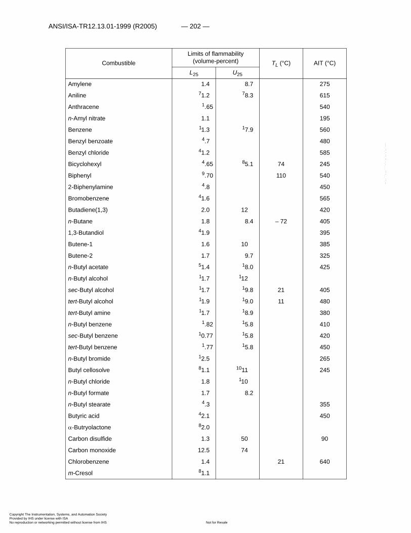
ANSI/ISA-TR12.13.01-1999 (R2005) — 202 —
Copyright The InstrumProvided by IHS underNo reproduction or net
--`,,```,,,,````-`-`,,`,,`,`,,`---
CombustibleLimits of flammability
(volume-percent) TL (°C) AIT (°C)L25 U25
Amylene 1.4 8.7 275
Aniline 71.2 78.3 615
Anthracene 1.65 540
n-Amyl nitrate 1.1 195
Benzene 11.3 17.9 560
Benzyl benzoate 4.7 480
Benzyl chloride 41.2 585
Bicyclohexyl 4.65 85.1 74 245
Biphenyl 9.70 110 540
2-Biphenylamine 4.8 450
Bromobenzene 41.6 565
Butadiene(1,3) 2.0 12 420
n-Butane 1.8 8.4 – 72 405
1,3-Butandiol 41.9 395
Butene-1 1.6 10 385
Butene-2 1.7 9.7 325
n-Butyl acetate 51.4 18.0 425
n-Butyl alcohol 11.7 112
sec-Butyl alcohol 11.7 19.8 21 405
tert-Butyl alcohol 11.9 19.0 11 480
tert-Butyl amine 11.7 18.9 380
n-Butyl benzene 1.82 15.8 410
sec-Butyl benzene 10.77 15.8 420
tert-Butyl benzene 1.77 15.8 450
n-Butyl bromide 12.5 265
Butyl cellosolve 81.1 1011 245
n-Butyl chloride 1.8 110
n-Butyl formate 1.7 8.2
n-Butyl stearate 4.3 355
Butyric acid 42.1 450
�-Butryolactone 82.0
Carbon disulfide 1.3 50 90
Carbon monoxide 12.5 74
Chlorobenzene 1.4 21 640
m-Cresol 81.1
entation, Systems, and Automation Society license with ISA
Not for Resaleworking permitted without license from IHS
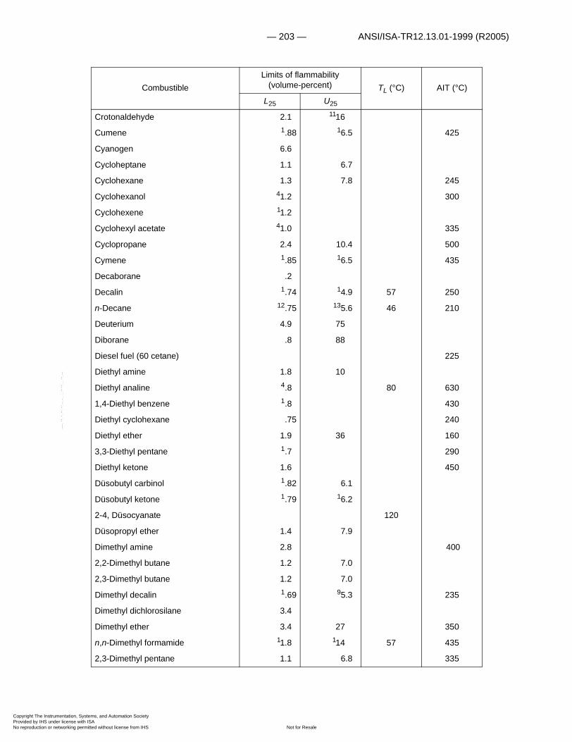
— 203 — ANSI/ISA-TR12.13.01-1999 (R2005)
Copyright The InstrumProvided by IHS underNo reproduction or net
CombustibleLimits of flammability
(volume-percent) TL (°C) AIT (°C)L25 U25
Crotonaldehyde 2.1 1116
Cumene 1.88 16.5 425
Cyanogen 6.6
Cycloheptane 1.1 6.7
Cyclohexane 1.3 7.8 245
Cyclohexanol 41.2 300
Cyclohexene 11.2
Cyclohexyl acetate 41.0 335
Cyclopropane 2.4 10.4 500
Cymene 1.85 16.5 435
Decaborane .2
Decalin 1.74 14.9 57 250
n-Decane 12.75 135.6 46 210
Deuterium 4.9 75
Diborane .8 88
Diesel fuel (60 cetane) 225
Diethyl amine 1.8 10
Diethyl analine 4.8 80 630
1,4-Diethyl benzene 1.8 430
Diethyl cyclohexane .75 240
Diethyl ether 1.9 36 160
3,3-Diethyl pentane 1.7 290
Diethyl ketone 1.6 450
Düsobutyl carbinol 1.82 6.1
Düsobutyl ketone 1.79 16.2
2-4, Düsocyanate 120
Düsopropyl ether 1.4 7.9
Dimethyl amine 2.8 400
2,2-Dimethyl butane 1.2 7.0
2,3-Dimethyl butane 1.2 7.0
Dimethyl decalin 1.69 95.3 235
Dimethyl dichlorosilane 3.4
Dimethyl ether 3.4 27 350
n,n-Dimethyl formamide 11.8 114 57 435
2,3-Dimethyl pentane 1.1 6.8 335
--`,,```,,,,````-`-`,,`,,`,`,,`---
entation, Systems, and Automation Society license with ISA
Not for Resaleworking permitted without license from IHS
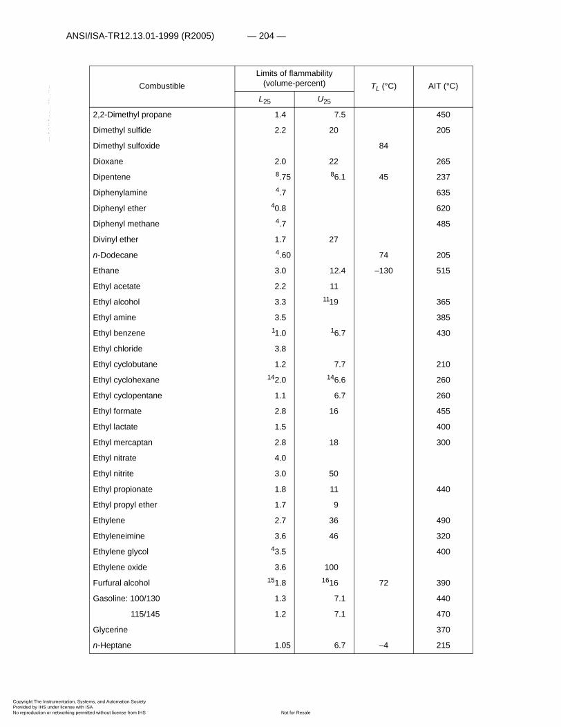
ANSI/ISA-TR12.13.01-1999 (R2005) — 204 —
Copyright The InstrumProvided by IHS underNo reproduction or net
--`,,```,,,,````-`-`,,`,,`,`,,`---
CombustibleLimits of flammability
(volume-percent) TL (°C) AIT (°C)L25 U25
2,2-Dimethyl propane 1.4 7.5 450
Dimethyl sulfide 2.2 20 205
Dimethyl sulfoxide 84
Dioxane 2.0 22 265
Dipentene 8.75 86.1 45 237
Diphenylamine 4.7 635
Diphenyl ether 40.8 620
Diphenyl methane 4.7 485
Divinyl ether 1.7 27
n-Dodecane 4.60 74 205
Ethane 3.0 12.4 –130 515
Ethyl acetate 2.2 11
Ethyl alcohol 3.3 1119 365
Ethyl amine 3.5 385
Ethyl benzene 11.0 16.7 430
Ethyl chloride 3.8
Ethyl cyclobutane 1.2 7.7 210
Ethyl cyclohexane 142.0 146.6 260
Ethyl cyclopentane 1.1 6.7 260
Ethyl formate 2.8 16 455
Ethyl lactate 1.5 400
Ethyl mercaptan 2.8 18 300
Ethyl nitrate 4.0
Ethyl nitrite 3.0 50
Ethyl propionate 1.8 11 440
Ethyl propyl ether 1.7 9
Ethylene 2.7 36 490
Ethyleneimine 3.6 46 320
Ethylene glycol 43.5 400
Ethylene oxide 3.6 100
Furfural alcohol 151.8 1616 72 390
Gasoline: 100/130 1.3 7.1 440
115/145 1.2 7.1 470
Glycerine 370
n-Heptane 1.05 6.7 –4 215
entation, Systems, and Automation Society license with ISA
Not for Resaleworking permitted without license from IHS
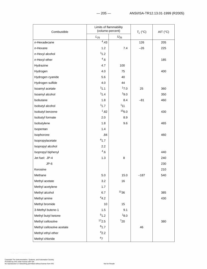
— 205 — ANSI/ISA-TR12.13.01-1999 (R2005)
Copyright The InstrumProvided by IHS underNo reproduction or net
--`,,```,,,,````-`
CombustibleLimits of flammability
(volume-percent) TL (°C) AIT (°C)L25 U25
n-Hexadecane 4.43 126 205
n-Hexane 1.2 7.4 –26 225
n-Hexyl alcohol 11.2
n-Hexyl ether 4.6 185
Hydrazine 4.7 100
Hydrogen 4.0 75 400
Hydrogen cyanide 5.6 40
Hydrogen sulfide 4.0 44
Isoamyl acetate 11.1 17.0 25 360
Isoamyl alcohol 11.4 19.0 350
lsobutane 1.8 8.4 –81 460
Isobutyl alcohol 11.7 111
Isobutyl benzene 1.82 106.0 430
Isobutyl formate 2.0 8.9
Isobutylene 1.8 9.6 465
Isopentan 1.4
Isophorone .84 460
Isopropylacetate 41.7
Isopropyl alcohol 2.2
Isopropyl biphenyl 4.6 440
Jet fuel: JP-4 1.3 8 240
JP-6 230
Kerosine 210
Methane 5.0 15.0 –187 540
Methyl acetate 3.2 16
Methyl acetylene 1.7
Methyl alcohol 6.7 1136 385
Methyl amine 44.2 430
Methyl bromide 10 15
3-Methyl butene-1 1.5 9.1
Methyl butyl ketone 51.2 18.0
Methyl cellosolve 172.5 720 380
Methyl cellosolve acetate 81.7 46
Methyl ethyl ether 42.2
Methyl chloride 47
entation, Systems, and Automation Society license with ISA
Not for Resaleworking permitted without license from IHS
-`,,`,,`,`,,`---

ANSI/ISA-TR12.13.01-1999 (R2005) — 206 —
Copyright The InstrumProvided by IHS underNo reproduction or net
--`,,```,,,,````-`-`,,`,,`,`,,`---
CombustibleLimits of flammability
(volume-percent) TL (°C) AIT (°C)L25 U25
Methyl cyclohexane 1.1 6.7 250
Methyl cyclopentadiene 11.3 17.6 49 445
Methyl ethyl ketone 1.9 10
Methyl ethyl ketone peroxide 40 390
Methyl formate 5.0 23 465
Methyl cyclohexanol 41.0 295
Methyl isobutyl carbinol 41.2 40
Methyl isopropenyl ketone 51.8 59.0
Methyl lactate 12.2
�-Methyl naphthalene 4.8 530
2, Methyl pentane 41.2
Methyl propionate 2.4 13
Methyl propyl ketone 1.6 8.2
Methyl styrene 41.0 49 495
Methyl vinyl ether 2.6 39
Methylene chloride 615
Monoisopropyl bicyclohexyl .52 184.1 124 230
2-Monoisopropyl biphenyl 10.53 183.2 141 435
Monomethylhydrazine 4
Naphthalene 19.88 205.9 526
Nicotine 1.75
Nitroethane 3.4 30
Nitromethane 7.3 33
1-Nitropropane 2.2 34
2-Nitropropane 2.5 27
n-Nonane 21.85 31 205
n-Octane 0.95 13 220
Paraldehyde 1.3
Pentaborane .42
n-Pentane 1.4 7.8 –48 260
Pentamethylene glycol 335
Phthalic anhydride 71.2 229.2 140 570
3-Picoline 41.4 500
Pinane 23.74 237.2
Propadiene 2.16
entation, Systems, and Automation Society license with ISA
Not for Resaleworking permitted without license from IHS
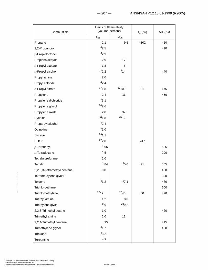
— 207 — ANSI/ISA-TR12.13.01-1999 (R2005)
Copyright The InstrumProvided by IHS underNo reproduction or net
--`,,```,,,,````-`-`,,`,,`,`,,`---
CombustibleLimits of flammability
(volume-percent) TL (°C) AIT (°C)L25 U25
Propane 2.1 9.5 –102 450
1,2-Propandiol 42.5 410
-Propiolactone 32.9
Propionaldehyde 2.9 17
n-Propyl acetate 1.8 8
n-Propyl alcohol 122.2 114 440
Propyl amine 2.0
Propyl chloride 42.4
n-Propyl nitrate 171.8 17100 21 175
Propylene 2.4 11 460
Propylene dichloride 43.1
Propylene glycol 242.6
Propylene oxide 2.8 37
Pyridine 111.8 2512
Propargyl alcohol 52.4
Quinoline 41.0
Styrene 261.1
Sulfur 272.0 247
p-Terphenyl 4.96 535
n-Tetradecane 4.5 200
Tetrahydrofurane 2.0
Tetralin 1.84 85.0 71 385
2,2,3,3-Tetramethyl pentane 0.8 430
Tetramethylene glycol 390
Toluene 11.2 17.1 480
Trichloroethane 500
Trichloroethylene 2812 2540 30 420
Triethyl amine 1.2 8.0
Triethylene glycol 8.9 289.2
2,2,3-Trimethyl butane 1.0 420
Trimethyl amine 2.0 12
2,2,4-Trimethyl pentane .95 415
Trimethylene glycol 41.7 400
Trioxane 43.2
Turpentine 1.7
entation, Systems, and Automation Society license with ISA
Not for Resaleworking permitted without license from IHS

ANSI/ISA-TR12.13.01-1999 (R2005) — 208 —
Copyright The InstrumProvided by IHS underNo reproduction or net
--`,,```,,,,````-`-`,,`,,`,`,,`---
1t=100°C 11t=60°C 21t=43°C2t=47°C 12t=53°C 22t=195°C3t=75°C 13t=86°C 23t=160°C4Calculated 14t=130°C 24t=96°C5t=50°C 15t=72°C 25t=70°C6t=85°C 16t=117°C 26t=29°C7t=140°C 17t=125°C 27t=247°C8t=150°C 18t=200°C 28t=30°C9t=110°C 19t=78°C 29t=203°C10t=-175°C 20t=122°C
CombustibleLimits of flammability
(volume-percent) TL (°C) AIT (°C)
L25 U25
Unsymmetrical dimethylhydrazine 2.0 95
Vinyl acetate 2.6
Vinyl chloride 3.6 33
m-Xylene 11.1 16.4 530
o-Xylene 11.1 16.4 465
p-Xylene 11.1 16.6 530
entation, Systems, and Automation Society license with ISA
Not for Resaleworking permitted without license from IHS

— 209 — ANSI/ISA-TR12.13.01-1999 (R2005)
Copyright The InstrumProvided by IHS underNo reproduction or net
--`,,```,,,,````-`-`,,`,,`,`,,`---
Appendix B Stoichiometric Composition
The stoichiometric composition (Cst) of a combustible vapor CnHmO�Fk in air may be obtained from the equation
.
Thus,
volume-percent,
where 4.773 is the reciprocal of 0.2095, the molar concentration of oxygen in dry air. The following table lists the values of Cst for a range of
values from 0.5 to 30.75:
N1 0 0.25 0.50 0.75
0 — — 29.53 21.83
1 17.32 14.35 12.25 10.69
2 9.48 8.52 7.73 7.08
3 6.53 6.05 5.65 5.29
4 4.97 4.70 4.45 4.22
5 4.02 3.84 3.67 3.51
6 3.37 3.24 3.12 3.01
7 2.90 2.81 2.72 2.63
8 2.55 2.48 2.40 2.34
9 2.27 2.21 2.16 2.10
10 2.05 2.00 1.96 1.91
11 1.87 1.83 1.79 1.75
12 1.72 1.68 1.65 1.62
13 1.59 1.56 1.53 1.50
14 1.47 1.45 1.42 1.40
15 1.38 1.36 1.33 1.31
16 1.29 1.27 1.25 1.24
CnHmOFk n m k– 2�–4
-------------------------+� �� �O2 nCO2
m k–2
-------------� �� �� H2O kHF+�+
Cst100
1 4.773 n m k– 2�–4
-------------------------+� �� �+
----------------------------------------------------------------=
n m k– 2�–4-------------------------+� �
� �
entation, Systems, and Automation Society license with ISA
Not for Resaleworking permitted without license from IHS

ANSI/ISA-TR12.13.01-1999 (R2005) — 210 —
Copyright The InstrumProvided by IHS underNo reproduction or net
--`,,```,,,,````-`-`,,`,,`,`,,`---
1 ; where n, m, �, and k are the number of carbon, hydrogen, oxygen, and halogen atoms, respectively, in the combustible.
For example, the stoichiometric mixture composition of acetyl chloride (C2H3OCl) in air may be found by noting that
.
The entry for N=2.0 in the preceding table is 9.48 volume-percent, which is the value of Cst for this combustible in air.
N1 0 0.25 0.50 0.75
17 1.22 1.20 1.18 1.17
18 1.15 1.13 1.12 1.10
19 1.09 1.08 1.06 1.05
20 1.04 1.02 1.01 1.00
21 .99 .98 .97 .95
22 .94 .93 .92 .91
23 .90 .89 .88 .87
24 .87 .86 .85 .84
25 .83 .82 .81 .81
26 .80 .79 .78 .78
27 .77 .76 .76 .75
28 .74 .74 .73 .72
29 .72 .71 .71 .70
30 .69 .69 .68 .68
N n m k– 2�–4-------------------------+=
N n m k– 2�–4
------------------------- 2 3 1– 2–4
--------------------- 2.0=+=+=
entation, Systems, and Automation Society license with ISA
Not for Resaleworking permitted without license from IHS

— 211 — ANSI/ISA-TR12.13.01-1999 (R2005)
Copyright The InstrumProvided by IHS underNo reproduction or net
--`,,```,,,,````-`-`,,`,,`,`,,`---
Appendix C Heat Contents of Gases
(Kcal/mole1)
1Gordon, J. S. Thermodynamics of High Temperature Gas Mixtures and Application to Combustion Problems. WADC Technical Report 57-33, January 1957, 172 pp.
T, °K CO2 H2O O2 N2
298.16 0 0 0 0
300 .017 .014 .013 .013
400 .941 .823 .723 .709
500 1.986 1.653 1.4541 1.412
600 3.085 2.508 2.2094 2.125
700 4.244 3.389 2.9873 2.852
800 5.452 4.298 3.7849 3.595
900 6.700 5.238 4.5990 4.354
1,000 7.983 6.208 5.4265 5.129
1,100 9.293 7.208 6.265 5.917
1,200 10.630 8.238 7.114 6.717
1,300 11.987 9.297 7.970 7.529
1,400 13.360 10.382 8.834 8.349
1,500 14.749 11.494 9.705 9.178
1,600 16.150 12.627 10.582 10.014
1,700 17.563 13.785 11.464 10.857
1,800 18.985 14.962 12.353 11.705
1,900 20.416 16.157 13.248 12.559
2,000 21.855 17.372 14.148 13.417
2,100 23.301 18.600 15.053 14.278
2,200 24.753 19.843 15.965 15.144
2,300 26.210 21.101 16.881 16.012
2,400 27.672 22.371 17.803 16.884
2,500 29.140 23.652 18.731 17.758
entation, Systems, and Automation Society license with ISA
Not for Resaleworking permitted without license from IHS

Copyright The InstrumProvided by IHS underNo reproduction or net
This page intentionally left blank.
--`,,```,,,,````-`-`,,`,,`,`,,`---
entation, Systems, and Automation Society license with ISA
Not for Resaleworking permitted without license from IHS

— 213 — ANSI/ISA-TR12.13.01-1999 (R2005)
Copyright The InstrumProvided by IHS underNo reproduction or net
Appendix D Definitions of Principal Symbols
Symbol: DefinitionA Constant.A� Area.a Velocity of sound.B Constant.Cst Stoichiometric composition.�Hc Heat of combustion.K Ratio of duct area to vent area.k Thermal conductivity.L Lower limit of flammability.L* Modified lower limit value.Lave Average carbon chain length for paraffin
hydrocarbons and correlation parameter for aromatic hydrocarbons.
Lt Lower limit of flammability at t°C.L/D Length to diameter ratio.M Molecular weight.M1 Mach number.NO2 Equilibrium mixture of NO2 and N2O4 at a
specified temperature and pressure.n Number of moles.P Pressure.Pm Maximum pressure.�P Pressure rise.p Partial pressure.Su Burning velocity,T Absolute temperature.t Temperature.
Time delay before ignition.U Upper limit of flammability.Ut Upper limit of flammability at t°C.V Volume.V� Critical approach velocity.
Liquid regression rate.� Specific heat ratio.
�
�
--`,,```,,,,````-`-`,,`,,`,`,,`---
entation, Systems, and Automation Society license with ISA
Not for Resaleworking permitted without license from IHS

Copyright The InstrumProvided by IHS underNo reproduction or net
This page intentionally left blank.
--`,,```,,,,````-`-`,,`,,`,`,,`---
entation, Systems, and Automation Society license with ISA
Not for Resaleworking permitted without license from IHS

Copyright The InstrumProvided by IHS underNo reproduction or net
entation, Systems, and Automation Society license with ISA
Not for Resaleworking permitted without license from IHS
--`,,```,,,,````-`-`,,`,,`,`,,`---

Copyright The InstrumProvided by IHS underNo reproduction or net
Developing and promulgating technically sound consensus standards, recommended practices, and technical reports is one of ISA’s primary goals. To achieve this goal, the Standards and Practices Department relies on the technical expertise and efforts of volunteer committee members, chairmen, and reviewers.
ISA is an American National Standards Institute (ANSI) accredited organization. ISA administers United States Technical Advisory Groups (USTAGs) and provides secretariat support for International Electrotechnical Commission (IEC) and International Organization for Standardization (ISO) committees that develop process measurement and control standards. To obtain additional information on the Society’s standards program, please write:
ISAAttn: Standards Department67 Alexander DriveP.O. Box 12277Research Triangle Park, NC 27709
ISBN 1-55617-697-Xentation, Systems, and Automation Society license with ISA
Not for Resaleworking permitted without license from IHS
--`,,```,,,,````-`-`,,`,,`,`,,`---