answers to chapter 2 review questions · · 2017-08-29answers to chapter 2 review questions 1....
TRANSCRIPT

Answers to Chapter 2 Review Questions
1. To accept signals from the machine or process devices and to convert them into signals that can be used by the controller
2. To convert controller signals into external signals that are used to control the machine or process
3. a) A rack that is located away from the processor module near the field devices b) To minimize the amount of wiring required
4. By its address
5. Type refers to an input or output Slot refers to the physical location of the I/O module Word and bit refers to the actual module terminal connection
6. Bit level addressing specifies a discrete device that is connected to a specific terminal. Word level addressing specifies an analog device connected to a module that uses a word of information.
7. In tag-based addressing you use a tag (alphanumeric name) to address data (variables). In rack/slot-based addressing a fixed numeric format is used to identify the address data.
8. An input/output PC interface card
9. Combination I/O modules
10. Connections for the power supply
11. For ease of wiring and replacing modules
12. The advantage with the high-density module is that it is possible to install up to 64 inputs or outputs in one slot for greater space savings. The disadvantage is that the high-density output modules cannot handle as much current per output.
13. ON/OFF devices such as selector switches, pushbuttons and limit switches
14. ON/OFF devices such as lights, solenoids and motor starters
15. The backplane supplies current and voltage for the modules from the power supply
16. An optical isolator is used to provide electrical isolation between the field wiring and the PLC backplane internal circuitry.

17. Power and Logic sections
18. Senses when a signal is received Converts the input signal to the correct voltage level Isolates the PLC from the input voltage or current Sends a signal to the processor indicating which sensor originated the signal
19. Triac
20. a) 1 amp per point b) A control relay is connected to the output module. The contacts of the control relay are then used to control the larger load.
21. Transistor
22. A discrete relay-type module uses an electromechanical relay element for switching which allow it to work for AC or DC applications.
23. a) Sinking and sourcing are terms used to describe a current signal flow relationship between field input and output devices in a control system and their power supply. b) Sourcing
24. Discrete I/O modules allow only ON/OFF devices to be connected. Analog I/O modules allow analog or varying voltage or current devices to be connected.
25. Used to convert analog signals to an equivalent digital value
26. Used to convert digital signals to an equivalent analog value
27. Voltage sensing and current sensing
28. Temperature, speed, level, flow, weight, pressure, and position
29. A twisted shielded pair cable is used in wiring the circuit to reduce unwanted electrical noise signals that can be induced in the conductors from other wiring
30. Unipolar modules can accept an input signal that varies in the positive direction only. Bipolar signals swing between a maximum negative value and a maximum positive value.
31. The analog input channel is capable of sensing voltages down to 0.3V increments.
32. The loop power may be supplied by the sensor or may be provided by the analog output module
33. Control valves, chart recorder, electronic drives

34. a) Used to count pulses such as motor encoders that occur at very high speeds b) Allows the use of thumbwheel switches for feeding information to a PLC c) Allows the transmitting and receiving of TTL signals for communication with the PLC’s processor d) Used to monitor the output of incremental or absolute encoders e) Allows the transmitting and receiving of ASCII files f) Provides pulse trains to a stepper-motor translator, which enables control of a stepper motor g) Enables a PLC to operate devices that require BCD-coded signals
35. a) Used to maintain a process variable such as temperature, flow, level, or speed within set limits of a specified set point. b) Used in applications involving accurate high-speed machining and packaging operations c) Used to establish point-to-pint connections with other intelligent devices for the exchange of data
36. a) Specifies the magnitude and type of voltage signal that will be accepted by the input b) Specifies a minimum ON-state voltage that is the minimum voltage at which logic 1 is recognized as absolutely ON; and a maximum OFF-state voltage which is the voltage at which logic 0 is recognized as absolutely OFF c) Specifies the minimum input current that the input devices must be capable of driving to operate the input circuit d) Specifies what the maximum temperature of the air surrounding the I/O modules should be for best operating conditions e) Specifies the maximum time duration required by an input module's circuitry to recognize that a field device has switched ON (input ON-delay) or switched OFF (input OFF-delay) f) Specifies the magnitude and type of user supply voltage at which a discrete output module is designed to operate g) Specifies the maximum current that a single output and the module as a whole can safely carry under load (at rated voltage) h) Specifies the maximum inrush current and duration for which an output circuit can exceed its maximum continuous current rating i) This specification will designate whether the particular module's design has individual protection for each circuit or if fuse protection is provided for groups (e.g. 4 or 8) of outputs j) Specifies the amount of current still conducting through an output circuit even after the output has been turned off k) Rates the module's capacity for sustaining an excessive voltage at its input or output terminal l) This specification defines the number of field inputs or outputs that can be connected to a single module m) This value indicates the amount of current the module requires from the backplane
37. a) Specifies the number of analog channels that can be connected to the module b) The voltage or current signal ranges that an analog input module is designed to accept c) This specification defines the current or voltage signal ranges that a particular analog

output module is designed to output under program control d) Analog input circuits are usually protected against accidentally connecting a voltage that exceeds the specified input voltage range e) This specification determines the smallest measureable unit of current or voltage the module can measure f) For analog I/Os, these values must be matched to the external device connected to the module g) Refers to an analog module’s ability to prevent noise from interfering with data integrity on a single channel and from channel to channel on the module
38. The CPU section executes the program and makes the decisions needed by the PLC to operate and communicate with other modules. The memory section electronically stores the PLC program along with other retrievable digital information
39. a) The power supply converts 115 VAC or 230 VAC into the usable DC voltage required by the CPU, memory, and I/O electronic circuitry b) the length of time a PLC can tolerate a power loss
40. Allows transfer of control to the second processor in the event of a processor fault
41. Run mode, program mode, and remote mode
42. Timing, counting, latching, comparing, motion control and complex math functions
43. Ground yourself by touching a conductive surface before handling static-sensitive components Wear a wrist strap that provides a path to bleed off any charge that may build up during work Be careful not to touch the backplane connector or connector pins of the PLC system (always handle the circuit cards by the edge if possible) Be careful not to touch other circuit components in a module when you configure or replace its internal components When not in use, store modules in its static-shield bag.
44. a) Data are stored in memory locations by a process called writing b) Data are retrieved from memory by what is referred to as readingc) Individual piece of memory in the form of 1’s or 0’s d) Memory location refers to an address in the CPU’s memory where a binary word can be stored e) Memory utilization refers to the number of memory locations required to store each type of instruction
45. a) The status of all input and output devices b) 1 c) 0 d) 1

e) 0
46. To be sure that the PLC memory has not been corrupted
47. Volatile: Loses all its stored information if all operating power is lost or removed. Memory is easily altered and usually supported by a battery backup power supply Nonvolatile: Retains stored information when the power is accidentally or intentionally removed. Memory is generally unalterable.
48. ROM is normally used to store the programs and data that define the capabilities of the PLC.
49. RAM is used as a temporary storage area of data that may need to be quickly changed
50. An EEPROM memory module is used to store, back up, or transfer PLC programs
51. They are extremely fast at saving and retrieving files
52. Allows the user to enter, change or monitor a PLC program
53. Handheld programmers are compact, inexpensive, and easy to use but they have limited display capabilities.
54. Appropriate programming software
55. Typical capabilities of the programming software include on-line and off-line program editing, on-line program monitoring, program documentation, diagnosing malfunctions in the PLC and troubleshooting the controlled system
56. One
57. Replace hard-wired pushbuttons and pilot lights with realistic-looking icons Show operations in graphic format Allow the operator to change timer and counter presets Show alarms, complete with time of occurrence and locations Display variables as they change over time
58. Set up the communication with the PLC. Create the tag database.
Insert the graphical objects on the screen. Animate the objects.
59. Values of process variables, such as flow, temperature over a period of time.
60. The changing a input or output quantity from one notation to another.
61. A transducer converts a field device's variable (e.g., pressure, temperature etc.) into a very low-level electric signal (current or voltage).

62. A base tag defines a memory location where data are stored. An alias tag is used to create an alternate name (alias) for a tag.
Copyright (c) 2017 McGraw-Hill Education. All rights reserved. No reproduction or distribution without the prior written consent of McGraw-Hill Education.
1
CHAPTER 2 PLC Hardware Components
TEST 2 . 1
Choose the letter that best completes the statement. Answer
1. A ____ is an example of a device that could be used to 1. d
provide a discrete input to a PLC.
a) pushbutton
b) selector switch
c) limit switch
d) all of the above
2. A ____ is an example of an actuator that could be 2. b
controlled by a discrete output from a PLC.
a) pushbutton
b) motor starter
c) limit switch
d) all of the above
3. A/An ____ input or output is a continuously variable 3. d
signal within a designated range.
a) discrete
b) digital
c) BCD
d) analog

Copyright (c) 2017 McGraw-Hill Education. All rights reserved. No reproduction or distribution without the prior written consent of McGraw-Hill Education.
2
4. One function of a PLC input interface module is to: 4. a
a) accept signals from field devices and convert them
into signals that can be used by the processor.
b) convert signals from the processing unit into values that
can be used to control the machine or process.
c) input signals from the programming device and convert them
into signals that can be used by the CPU.
d) interpret and execute the user program that controls the machine
or process.
5. The location of a specific input or output field device is 5. d
identified by the processor by means of its:
a) voltage rating. c) wattage rating.
b) current rating. d) address.
6. A discrete output interface module is designed to provide: 6. c
a) output voltages only in the 5 VDC range.
b) varying AC or DC voltages depending on the type of module selected.
c) ON/OFF switching of the output field device.
d) binary-coded outputs.
7. The following statement that does not apply to the 7. b
optical isolator circuit used in I/O modules is that it:
a) separates high voltage and low voltage circuits
b) rectifies AC signals.
c) prevents damage caused by line voltage transients.
d) reduces the effect of electrical noise.

Copyright (c) 2017 McGraw-Hill Education. All rights reserved. No reproduction or distribution without the prior written consent of McGraw-Hill Education.
3
8. Individual outputs of a typical AC output interface module 8. a
usually have a maximum current rating of about:
a) 1 A or 2 A. c) 50 mA or 100 mA.
b) 25 A or 50 A. d) 250 µA or 500 µA
9. Which of the following input field devices would most 9. d
likely be used with an analog interface input module?
a) Pushbutton c) Selector switch
b) Limit switch d) Thermocouple
10. The "ON state input voltage range" specification refers to: 10. d
a) the type of voltage device that will be accepted by the input.
b) range of leakage voltage present at the input in its ON state.
c) minimum and maximum output operating voltages.
d) voltage at which the input signal is recognized as being ON.
11. Volatile memory elements can be classified as those that: 11. a
a) do not retain stored information when the power is removed.
b) retain stored information when the power is removed.
c) do not require a battery backup.
d) both b and c.
12. ______ memory is used by the PLC's operating system. 12. d
a) RAM c) Flash
b) EEPROM d) ROM

Copyright (c) 2017 McGraw-Hill Education. All rights reserved. No reproduction or distribution without the prior written consent of McGraw-Hill Education.
4
13. _____ is a type of memory commonly used for temporary 13. a
storage of data that may need to be quickly changed.
a) RAM c) EPROM
b) ROM d) EEPROM
14. The most common form of memory used to store, back up, 14. d
or transfer PLC programs is:
a) RAM c) EEPROM
b) Flash EEPROM d) both b and c
15. In event of a power interruption, a _____ is used in some 15. b
processors to provide power to the RAM.
a) inductor c) transistor
b) capacitor d resistor
16. Which of the following is not a function of a 16. c
PLC programming device?
a) To enter the user program
b) To change the user program
c) To execute the user program
d) To monitor the user program
17. Status indicators are provided on each output 17. d
of an output module to indicate that the:
a) load has been operated.
b) input associated with the output is active.
c) module fuse has blown.

Copyright (c) 2017 McGraw-Hill Education. All rights reserved. No reproduction or distribution without the prior written consent of McGraw-Hill Education.
5
d) output is active.
18. The I/O system provides an interface between: 18. b
a) input modules and output modules.
b) the CPU and field equipment.
c) the CPU and I/O rack.
d) the I/O rack and I/O modules.
19. The PLC chassis comes in different sizes 19. c
according to the:
a) size of the program. c) number of slots they contain.
b) type of I/O modules used. d) all of the above.
20. The Allen-Bradley SLC-500 address I:2/4 refers to an: 20. c
a) Input module in slot 4, terminal 2.
b) Output module in slot 4, terminal 2.
c) Input module in slot 2, terminal 4.
d) Output module in slot 2, terminal 4.
21. The Allen-Bradley SLC-500 address O:3/0 refers to an: 21. b
a) Input module in slot 3, terminal 0.
b) Output module in slot 3, terminal 0.
c) Input module in slot 0, terminal 3.
d) Output module in slot 0, terminal 3.
22. For the I/O module of Figure 2-1, the arrows point to the: 22. d
a) status indicator connections.

Copyright (c) 2017 McGraw-Hill Education. All rights reserved. No reproduction or distribution without the prior written consent of McGraw-Hill Education.
6
b) input connections.
c) output connections.
d) power supply connections.
Figure 2-1 I/O module for question 22.
23. For the block diagram of the input module shown in 23. c
Figure 2-2, Section #1 represents the ____ and #2 the ____.
a) AC, DC.
b) DC, AC.
c) power, logic.
d) logic, power.
Figure 2-2 Block diagram for question 23.

Copyright (c) 2017 McGraw-Hill Education. All rights reserved. No reproduction or distribution without the prior written consent of McGraw-Hill Education.
7
24-1. The schematic diagram of Figure 2-3 is that of a(n): 24-1. c
a) discrete output module. c) discrete input module.
b) analog output module. d) analog input module.
24-2. The purpose of the filter section is to: 24-2. c
a) aid in fault diagnosis.
b) set the minimum level of voltage that can be detected.
c) protect against electrical noise interference.
d) separate the higher line voltage from the logic circuits .
24-3 The purpose of the zener diode (ZD) is to: 24-3. b
a) aid in fault diagnosis.
b) set the minimum level of voltage that can be detected.
c) protect against electrical noise interference.
d) separate the higher line voltage from the logic circuits .
24-4 The purpose of the LED indicator is to: 24-4. a
a) aid in fault diagnosis.
b) set the minimum level of voltage that can be detected.
c) protect against electrical noise interference.
d) separate the higher line voltage from the logic circuits .
24-5 The purpose of the optical isolator is to 24-5. d
a) aid in fault diagnosis.
b) set the minimum level of voltage that can be detected.
c) protect against electrical noise interference.
d) separate the higher line voltage from the logic circuits .

Copyright (c) 2017 McGraw-Hill Education. All rights reserved. No reproduction or distribution without the prior written consent of McGraw-Hill Education.
8
Figure 2-3 Schematic diagram for question 24.
25. For the block diagram of the output module shown in 25. b
Figure 2-4, the input comes from the:
a) input field device
b) processor.
c) output field device.
d) line power supply.
Figure 2-4 Block diagram for question 25.
26-1. The schematic diagram of Figure 2-5 is that of a(n): 26-1. a
a) discrete output module. c) discrete input module.
b) analog output module. d) analog input module.
26-2. The input signal to the module comes from: 26-2. c
a) the input field device.

Copyright (c) 2017 McGraw-Hill Education. All rights reserved. No reproduction or distribution without the prior written consent of McGraw-Hill Education.
9
b) the output field device.
c) internal logic circuitry of the processor.
d) either a or b.
26-3 The purpose of the triac switch is to: 26-3. a
a) turn the load ON and OFF.
b) vary the current flow to the load in accordance with the input
signal level.
c) vary the voltage across the load in accordance with the input
signal level.
d) both b and c.
26-4 When the triac is in the OFF state: 26-4. b
a) zero current always flows through the load.
b) a small leakage current may flow through the load.
c) the rated surge current flows through the lamp.
d) the rated nominal current flows through the lamp.
Figure 2-5 Schematic diagram for question 26.

Copyright (c) 2017 McGraw-Hill Education. All rights reserved. No reproduction or distribution without the prior written consent of McGraw-Hill Education.
10
27. The schematic diagram of Figure 2-6 is an example of 27. d
how a PLC output module is connected to:
a) isolate the load from the controller. c) vary the speed of a motor.
b) control a high resistance. d) control a high current load.
Figure 2-6 Schematic diagram for question 27.
28. Which of the following devices can be used for switching 28. d
the output of a discrete DC output module?
a) Transistor. c) relay.
b) Triac. d) either a or c.
29. The current sourcing sensor shown in Figure 2-7 29. a
must be matched with a _____ PLC input module.
a) current sinking.
b) current sourcing.
c) alternating current.
d) either a or b.

Copyright (c) 2017 McGraw-Hill Education. All rights reserved. No reproduction or distribution without the prior written consent of McGraw-Hill Education.
11
Figure 2-7 Current sourcing sensor for question 29.
30. Typical analog inputs and outputs can vary from 30. d
a) 0 to 20 mA
b) 4 to 20 mA
c) 0 to 10 volts
d) all of the above
31. For the block diagram of the analog PLC control 31. d
shown in Figure 2-8, which part has a binary
input and analog output value?
a) Level transmitter c) Processor
b) Input module d) Output module
Figure 2-8 Block diagram for question 31.
Copyright (c) 2017 McGraw-Hill Education. All rights reserved. No reproduction or distribution without the prior written consent of McGraw-Hill Education.
12
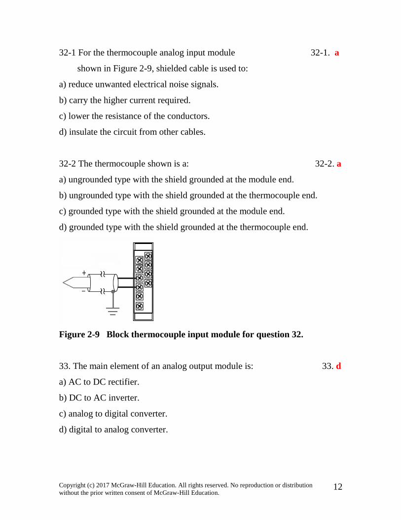
32-1 For the thermocouple analog input module 32-1. a
shown in Figure 2-9, shielded cable is used to:
a) reduce unwanted electrical noise signals.
b) carry the higher current required.
c) lower the resistance of the conductors.
d) insulate the circuit from other cables.
32-2 The thermocouple shown is a: 32-2. a
a) ungrounded type with the shield grounded at the module end.
b) ungrounded type with the shield grounded at the thermocouple end.
c) grounded type with the shield grounded at the module end.
d) grounded type with the shield grounded at the thermocouple end.
Figure 2-9 Block thermocouple input module for question 32.
33. The main element of an analog output module is: 33. d
a) AC to DC rectifier.
b) DC to AC inverter.
c) analog to digital converter.
d) digital to analog converter.

Copyright (c) 2017 McGraw-Hill Education. All rights reserved. No reproduction or distribution without the prior written consent of McGraw-Hill Education.
13
34. For the PLC analog I/O control system shown in 34. a
Figure 2-10, the fluid flow is controlled by
a) varying the amount of the valve opening.
b) switching the valve ON and OFF.
c) switching the level sensor ON and OFF.
d) varying the position of the level sensor.
Figure 2-10 Analog I/O system for question 34.
35. Which of the following special I/O modules would 35. b
be used to operate a seven-segment LED Display?
a) Encoder-counter module.
b) BCD-output module.
c) Stepper-motor module.
d) High-speed counter module.
36. A ______ module is used to establish connections 36. b
for the exchange of data.
a) thumbwheel
b) communication
c) servo
d) PID

Copyright (c) 2017 McGraw-Hill Education. All rights reserved. No reproduction or distribution without the prior written consent of McGraw-Hill Education.
14
37. High-density I/O modules: 37. a
a) may have up to 64 inputs or outputs per module.
b) require more space.
c) can handle greater amounts of current per output.
d) all of the above.
38. Discrete I/O modules can be classified as: 38. a
a) bit oriented. c) processor oriented.
b) word oriented. d) power supply oriented.
39. Which of the following specifications defines the number of 39. b
field inputs or outputs that can be connected to a single module?
a) Electrical isolation.
b) Points per module.
c) Threshold voltage.
d) Current per input.
40. The _______ of an analog I/O module specifies how 40. c
accurately an analog value can be represented digitally.
a) number of inputs and outputs per card
b) input impedance and capacitance
c) resolution
d) common mode rejection ratio
41. The processor module of the PLC is where the: 41. a
a) ladder logic program is stored.
b) input connections are made.

Copyright (c) 2017 McGraw-Hill Education. All rights reserved. No reproduction or distribution without the prior written consent of McGraw-Hill Education.
15
c) output connections are made.
d) sensors are located.
42. For the processor module shown in Figure 2-11, 42. d
Block 1 represents the ___ and Block 2 the ___.
a) input, output
b) output, input
c) memory, CPU
d) CPU, memory
Figure 2-11 Processor module for question 42.
43. When placed in the______ mode, the processor 43. a
does not scan/execute the ladder program.
a) program c) test
b) run d) remote

Copyright (c) 2017 McGraw-Hill Education. All rights reserved. No reproduction or distribution without the prior written consent of McGraw-Hill Education.
16
44. The most commonly used programming device is a: 44. a
a) personal computer.
b) dedicated industrial programming terminal.
c) hand-held programmer.
d) proprietary programming device.
45. Electronic components found in PLC modules 45. d
a) are not effected by electrostatic voltages.
b) can be damaged by electrostatic voltages.
c) can have their performance degraded by electrostatic voltages.
d) both b and c.
46. Batteries are used in a PLC's processor to 46. b
a) operate the status lights LEDs.
b) maintain data in volatile memory when line power is
removed from the processor.
c) maintain data in nonvolatile memory when line power is
removed from the processor.
d) maintain outputs through a power failure.
47. The ___ tag is often used to create a tag name to represent 47. c
a real world input or output.
a) base c) alias
b) predefined b) INT

Copyright (c) 2017 McGraw-Hill Education. All rights reserved. No reproduction or distribution without the prior written consent of McGraw-Hill Education.
17
48. The resizing of a signal to meet the requirements of the 48. a
using component of a PLC system is known as
a) scaling c) amplification
b) grading b) protocol
49. For the HMI package shown, the unlabeled block 49. b
represents the
a) processor c) input module
b) tag database b) output module
50. A fault condition which is present but the HMI alarm 50. a
message has not been acknowledged by the operator is
said to be in the ___ state.
a) active c) ready
b) inactive b) OK
51. Which of the following HMI program features provides the 51 a
ability to chart the progress of a process in real time in a
manner similar to that of a strip chart recorder?
a) Tend c) Graphics Library
b) Alarms b) Event History

Copyright (c) 2017 McGraw-Hill Education. All rights reserved. No reproduction or distribution without the prior written consent of McGraw-Hill Education.
18
CHAPTER 2
PLC Hardware Components
TEST 2 . 2
Place the answers to the following questions in the
answer column at the right. Answer
1. An analog input or output is a signal that varies 1. True
continuously within a certain range. (True of False)
2. The I/O section of a PLC system can consist 2. modules
of an I/O rack and individual I/O __ .
3. The location of a module within a rack and the terminal 3. address
number of a module to which an input or output device
is connected will determine the device's ____.
4. Most input modules have blown fuse indicators. 4. False
(True or False)
5. The I/O address is used by the processor to identify 5. located
where the device is ____.
6. A standard I/O module consists of a(n) 6a. circuit
(a) _________ board and a(n) (b) ____ assembly. 6b. terminal

Copyright (c) 2017 McGraw-Hill Education. All rights reserved. No reproduction or distribution without the prior written consent of McGraw-Hill Education.
19
7. I/O modules are designed to plug into a slot or connector. 7. True
(True or False)
8. Discrete I/O interfaces allow only ___ type devices to 8. ON/OFF
be connected.
9. I/O modules' circuitry can be divided into two 9a power
basic sections: the (a) _______ section and the 9b logic
(b) ________ section.
10. Optical isolation used in I/O modules helps to 10. True
reduce the effects of electrical noise. (True or False)
11. AC output modules often use a solid-state device 11. Triac
such as a(n) _____ to switch the output ON and OFF.
12. I/O modules are keyed to prevent unauthorized 12. False
personnel from removing them from the I/O rack.
(True or False)
13. The maximum current rating for the individual 13. False
outputs of an AC output module is usually in
the 20 to 30 ampere range. (True or False)
14. A(n) ________ relay is used for controlling 14. interposing
larger load currents.

Copyright (c) 2017 McGraw-Hill Education. All rights reserved. No reproduction or distribution without the prior written consent of McGraw-Hill Education.
20
15. Analog input interface modules contain 15. Analog to Digital
a(n) _____ converter circuit.
16. A thermocouple would be classified as an analog 16. True
input sensing device. (True or False)
17. Shielded twisted pair cable is used for connecting 17. True
to thermocouple inputs to reduce unwanted
electrical noise. (True or False)
18. Electrical noise usually causes permanent 18. False
operating errors. (True or False)
19. Match each of the following specifications with the appropriate description.
Place the number from the specifications list in the answer column.
SPECIFICATIONS
1) nominal current per input
2) ON-state input voltage range
3) OFF-state leakage current
4) electrical isolation
5) input delay
6) nominal input voltage
7) surge current
8) output voltage range
9) maximum output current rating
10) nominal output voltage
DESCRIPTIONS

Copyright (c) 2017 McGraw-Hill Education. All rights reserved. No reproduction or distribution without the prior written consent of McGraw-Hill Education.
21
a) Maximum voltage isolation between the I/O circuits 19a. 4
and the controller logic circuitry.
b) Maximum value of current that flows through the 19b. 3
output in its OFF state.
c) Maximum inrush current and duration an output 19c. 7
module can withstand.
d) Maximum current that a single output and the 19d. 9
module as a whole can safely carry.
e) Minimum and maximum output operating voltages. 19e. 8
f) Magnitude and type of voltage source that can be 19f. 10
controlled by the output.
g) Duration for which the input must be ON before 19g. 5
being recognized as a valid input.
h) Minimum input current that the input device must 19h. 1
be capable of driving to operate the input circuit.
i) Voltage level at which the input signal is 19i. 2
recognized as being ON.
j) Magnitude and type of voltage signal that will be 19j. 6
accepted by the input.
20. The processor continually interacts with the 20. I/O
_________ to interpret and execute the user program.
21. The processor may perform functions such as timing, 21. True
counting, and comparing in addition to
logic processing. (True or False)

Copyright (c) 2017 McGraw-Hill Education. All rights reserved. No reproduction or distribution without the prior written consent of McGraw-Hill Education.
22
22. Memory is where the control plan is held or 22. True
stored in the controller. (True or False)
23. One ___ is a memory location that may store one 23. bit
binary number that has the value of either 1 or 0.
24. A volatile memory will lose its programmed contents 24. True
if operating power is lost. (True or False)
25. A nonvolatile memory will retain its programmed 25. True
contents if operating power is lost. (True or False)
26. RAM memory is nonvolatile. (True or False) 26. False
27. Information stored in a RAM memory location 27. True
can be written into or read from. (True or False)
28. When a new program is loaded into a PLC’s memory, 28. True
the old program that was stored in the same locations
is over-written and essentially erased. (True or False)
29. The type of battery typically used PLC processors 29. lithium
is ____.
30. Flash memory functions similar to ___ memory. 30. EEPROM

Copyright (c) 2017 McGraw-Hill Education. All rights reserved. No reproduction or distribution without the prior written consent of McGraw-Hill Education.
23
31. Most PLC programming software will allow you to 31. False
develop programs on another manufacturer's PLC.
(True or False)
32. Analog signals can have only two states. 32. False
(True or False)
33. Memory modules used to copy a program from one 33. EEPROM
PLC to another usually contain ___ memory.
34. A modular PLC that has room for several I/O modules, 34. True
is capable of being customized for a particular application.
(True or False)
35. Remote I/O racks are linked to the local 35. communications
rack through a(n) ____ module.
36. In general, rack/slot-based addressing elements 36a. Type
include: (a) __, (b) __, and (c) __. 36b. Slot
36c. Word and Bit
37. I/O modules are normally installed or removed 37. False
while the PLC is powered. (True or False)
38. A module inserted into the wrong slot could 38. True
be damaged. (True or False)

Copyright (c) 2017 McGraw-Hill Education. All rights reserved. No reproduction or distribution without the prior written consent of McGraw-Hill Education.
24
39. Modules receive voltage and current for proper 39. backplane
operation from the _____ of the rack enclosure.
40. The two basic types of analog input modules are 40a. voltage
(a) ___sensing and (b) ___sensing. 40b. current
41. Intelligent I/O modules have their 41.microprocessor
own ____ on board.
42. A redundant PLC system is configured using 42. __True
two processors. (True or False)
43. Most PLC electronic components are not sensitive 43. __False
to electrostatic discharge. (True or False)
44. Answer each of the following for the I/O module and
status table shown in Figure 2-12.
a) The type of module shown is a(n) 44a. discrete
__ (discrete or analog) module.
b) The type of image table shown is a(n) __ image table. 44b. input
c) The status light indicator associated with device #1 44c. ON
would be ____. (ON or OFF)
d) The status light indicator associated with device #2 44d. OFF
would be ____. (ON or OFF)
e) The value stored in memory for device #1 would be ___. 44e. 1
f) The value stored in memory for device #2 would be ___. 44f. 0

Copyright (c) 2017 McGraw-Hill Education. All rights reserved. No reproduction or distribution without the prior written consent of McGraw-Hill Education.
25
Figure 2-12 I/O module and table for question 44.
45. Answer each of the following for the I/O module and
status table shown in Figure 2-13.
a) The type of module shown is a(n) 45a. discrete
__ (discrete or analog) module.
b) The type of image table shown is a(n) __ image table. 45b. output
c) The status light indicator associated with PL1 45c. ON
would be ____. (ON or OFF)
d) The status light indicator associated with PL2 45d. ON
would be ____. (ON or OFF)
e) PL1 would be switched ___. (ON or OFF). 45e. ON
f) PL2 would be switched ___. (ON or OFF). 45f. ON
Figure 2-13 I/O module and table for question 45.

Copyright (c) 2017 McGraw-Hill Education. All rights reserved. No reproduction or distribution without the prior written consent of McGraw-Hill Education.
26
46. One advantage of discrete relay contact output modules 46. True
is that they can be used with AC or DC devices. (True or False)
47. If you had a hand-held programming terminal 47. True
from one manufacturer you can program only
that manufacture's PLC using it. (True or False)
48. Hot swappable I/O modules are designed to be changed 48. True
with the power on and the PLC operating. (True or False)
49. Identify data types (a) __ , (b) __, and (c) shown 49a. bit
in Figure 2-14. 49b. byte
49c. word
Figure 2-14 Data types for question 49.
50. HMI screens are developed using a software package 50. True
on a PC which is downloaded into the PLC operator
interface device. (True or False)
51. Discrete means that each input or output has two states: 51. True
true (on) or false (off). (True or False)
52. Light is used in I/O modules to separate the real-world 52. True
electrical signals from the PLC internal electronic system.

Copyright (c) 2017 McGraw-Hill Education. All rights reserved. No reproduction or distribution without the prior written consent of McGraw-Hill Education.
27
53. Digital modules are also called discrete modules. 53. True
(True or False)
54. The sum of the backplane current drawn for all modules 54. True
in a chassis is used to select the appropriate chassis power
supply rating. (True or False)
Programming Assignments
For Chapter 2
1. For the PLC you will be working with, summarize the specifications for
the:
(a) input module(s)
(b) output module(s)
(c) processor
(d) power supply
Answers will vary according to the PLC used.
2. (a) Program your controller to operate according to Figure 2-15.
(b) Download the program to the PLC
(c) Run the program and observe the status of the bits stored in the
input and output image tables.

Copyright (c) 2017 McGraw-Hill Education. All rights reserved. No reproduction or distribution without the prior written consent of McGraw-Hill Education.
28
Figure 2-15 Program for assignment 2.
Answers will vary according to the PLC used.
3. (a) Program your controller to operate according to Figure 2-16.
(b) Download the program to the PLC
(c) Run the program and observe the status of the bits stored in the
input and output image tables.
Figure 2-16 Program for assignment 3.
Answers will vary according to the PLC used.
4. (a) Program your controller to operate according to Figure 2-17.
(b) Download the program to the PLC
(c) Run the program and observe the status of the bits stored in the
input and output image tables.

Copyright (c) 2017 McGraw-Hill Education. All rights reserved. No reproduction or distribution without the prior written consent of McGraw-Hill Education.
29
Figure 2-17 Program for assignment 4.
Answers will vary according to the PLC used.
5. (a) Program your controller to operate according to Figure 2-18.
(b) Download the program to the PLC
(c) Run the program and observe the status of the bits stored in the
input and output image tables.
Figure 2-18 Program for assignment 5.
Answers will vary according to the PLC used.

Copyright © 2017 McGraw-Hill Education. All rights reserved. No reproduction or distribution without
the prior written consent of McGraw-Hill Education.
Answers to Chapter 1 Review Problems
1.
2. 35 mV
3. a) 0.012 s
b) 0.00095 A
c) 140°F
4. a) I1:12/05
b) O0:20/07
5. The device would remain ON or energized at all times.
6. Programming software installed in the computer for each model of PLC to be programmed.