antenna and wave propagation iii b.tech-ii...
TRANSCRIPT
ANTENNA AND WAVE PROPAGATION
III B.TECH-II SEM
DEPT.OF.ECE
Prepared by
Mr.U.NARESH
Asst.Professor

ANTENNASS BASICS
• Definition of antenna parameters :
– Gain,
– Directivity,
– Effective aperture,
– Radiation Resistance,
– Band width,
– Beam width,
– Input Impedance.
• Matching – Baluns,
• Polarization mismatch,
• Antenna noise temperature,
• Radiation from oscillating dipole, Half wave dipole. Folded
dipole, Yagi array.

Antenna Background
• Maxwell (1831-79) Fundamental equations. (Scottish)
• Hertz (1857-94) First aerial propagation (German)
• Marconi (1874-1937) Transatlantic transmission (Italian)
• DeForest (Triode tube 1920) Signal generators (American)
• World War II (1939-45) Intense war-driven development

What is an Antenna?
An antenna is a way of converting the guided wavespresent in a waveguide, feeder cable or transmission lineinto radiating waves travelling in free space, or viceversa.
An antenna is a passive structure that serves astransition between a transmission line and air used totransmit and/or receive electromagnetic waves.
Converts Electrons to Photons of EM energy
It is a transducer which interfaces a circuit andfreespace

5
Only accelerated (or decelerated) charges radiate EM waves. A current with a time-harmonic variation (AC current) satisfies this
requirement.

6
The role of antennas
Antennas serve four primary functions:
• Spatial filterdirectionally-dependent sensitivity
• Polarization filterpolarization-dependent sensitivity
• Impedance transformer (50 Ω to 377Ω)transition between free space and transmission line
• Propagation mode adapterfrom free-space fields to guided waves
(e.g., transmission line, waveguide)

7
Antenna types
Horn antenna Parabolic reflector antennaHelical antenna

• Solid angle, WA and Radiation intensity, U
• Radiation pattern, Pn, sidelobes, HPBW
• Far field zone, rff
• Directivity, D or Gain, G
• Antenna radiation impedance, Rrad
• Effective Area, Ae
All of these parameters are expressed in terms of a transmission antenna, but are identically applicable to a receiving antenna. We’ll also study:
Antenna parameters

Isotropic antenna
• It’s an hypothetic antenna, i.e., it does not exist in real life, yet it’s used as a measuring bar for real antenna characteristics.
• It’s a point source that occupies a negligible space. Has no directional preference.
• Its pattern is simply a sphere so it has ,
beam area (WA) = Wisotropic= 4p [steradians].
4sin)1(
)1(
0
2
0
4
isotropic
dd
d

Isotropic Radiator:
A hypothetical lossless antenna having equal radiation in all directions.
Omnidirectional Radiator:
An antenna having an essentially nondirectional pattern in a given plane (e.g., in
azimuth) and a directional pattern in any orthogonal plane.
Directional Radiator:
An antenna having the property of radiating or receiving more effectively in some
directions than in others. Usually the maximum directivity is significantly greater
than that of a half-wave dipole.

Spherical coordinates
z (zenith)
x
y
= azimuth
= elevation=90=0
=0
=90=90

Solid Angle
s1 = r d s2 = r sin døs = r = arco dA = s1 s2
dA = r2 sin dø d= r2 dΩ

Radiation Intensity
• Is the power density per solid angle:
vector.Poynting asknown
alsodensity power theis
][W/m ˆRe 2
r
2
rH*E½
where
rU
r
P
P [W/sr]

Radiation Pattern
),(
),(
),(
),(),(
maxmax
U
UFn
P
P
Field pattern:),(
),(),(
max
E
EEn
Power pattern:
• A radiation pattern is a three-dimensional, graphicalrepresentation of the far-field radiation properties of an antennaas a function of space coordinates. The far-field region is a regionfar enough for the radiation pattern to be independent of thedistance from the antenna. The radiation pattern of a particularantenna can be measured by experiment or can be calculated, ifthe current distribution is known.
• Typically measured in two planes:
– E Plane
– H Plane

15
Three-dimensional representation of the
radiation pattern of a dipole antenna
Radiation pattern – variation of the field intensity of an antenna as an angular function with respect to the axis

16
Radiation Pattern Characteristics
• 3 dB beamwidth (HPBW)
• Sidelobes
• Nulls
• Front-to-back ratio
• Gain (approximate)
•Maximum signal
position

Antenna Pattern Parameters


Directivity and GAIN
G=ηD
“The ratio of the radiation intensity in a given direction
from the antenna to the radiation intensity averaged
over all directions.”
Max Radiation intensity from subject or test antenna
Max Radiation Intensity from reference (Isotropic)antenna with same power input.

Directivity and GAIN of an Antenna
The Directivity or Gain of an antenna is defined as the ratio of the maximum
value of the power radiated per unit solid angle to the average power radiated
per unit solid angle
Directivity is a fundamental antenna parameter. It is a measure of how
'directional' an antenna's radiation pattern is. An antenna that radiates equally in
all directions would have effectively zero directionality, and the directivity of
this type of antenna would be 1 (or 0 dB).
It measures the power density of the antenna radiates in the direction of its
strongest emission, versus the power density radiated by an ideal Isotropic
Radiator (which emits uniformly in all directions) radiating the same total
power.
Directivity is a component of its Gain, If lossless antenna, G=D

Gain or Directivity
An isotropic antenna and a practical antenna fed with the same power. Their patterns would compare as in the figure on the right.

Directivity and Gain
• All practical antennas radiate more than the isotropic antenna
in some directions and less in others.
• Gain is inherently directional; the gain of an antenna is
usually measured in the direction which it radiates best.
aveave /UUDD maxmaxmax /),( PP
“The directivity of an antenna is equal to the ratio of
the maximum power density Pmax to its average value
over a sphere as observed in the far field of an antenna”

Gain or Directivity
• Gain is measured by comparing an antenna to
a model antenna, typically the isotropic
antenna which radiates equally in all
directions.
rad
AVEP
r
dAA
D),(4
1/),(
2
P
P
),P(PP
/ /44
AisotropicAmax
rad
oP
UD
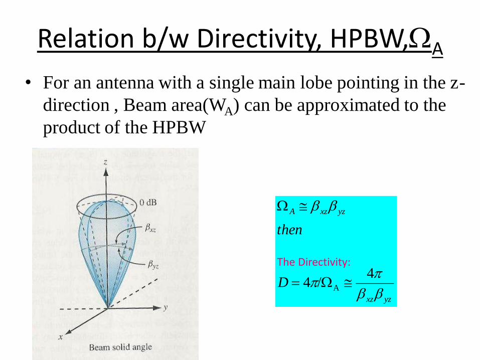
Relation b/w Directivity, HPBW,A
• For an antenna with a single main lobe pointing in the z-
direction , Beam area(WA) can be approximated to the
product of the HPBW
yzxz
yzxzA
D
then
4 /4 A
The Directivity:

Effective Aperture
“A useful parameter in calculating the received
power of an antenna is the effective area or effective
aperture”
Effective area or Effective aperture (square meters)
The effective area corresponds to the effective absorbance area
presented by an antenna to an incident plane wave. For an
aperture antenna, it is equal to or smaller than the physical
aperture. The relationship between the gain and the
wavelength isG Ae
42

THANK YOU

Prepared by
Mr.U.Naresh
Asst.Professor
Antennas Wave and Propagation

Wave Propagation
Ground-wave propagation
Sky-wave propagation
Line-of-sight propagation

Ground Wave Propagation

Ground Wave Propagation
Follows contour of the earth
Can Propagate considerable distances
Frequencies up to 2 MHz
Example
AM radio

Sky Wave Propagation

Sky Wave Propagation
Signal reflected from ionized layer of atmosphere back down to
earth
Signal can travel a number of hops, back and forth between
ionosphere and earth’s surface
Reflection effect caused by refraction
Examples
Amateur radio
CB radio

Line-of-Sight Propagation

Line-of-Sight Propagation
Transmitting and receiving antennas must be within line of sight Satellite communication – signal above 30 MHz not reflected by
ionosphere
Ground communication – antennas within effective line of site due to refraction
Refraction – bending of microwaves by the atmosphere Velocity of electromagnetic wave is a function of the density of the
medium
When wave changes medium, speed changes
Wave bends at the boundary between mediums

Line-of-Sight Equations
Optical line of sight
Effective, or radio, line of sight
d = distance between antenna and horizon (km)
h = antenna height (m)
K = adjustment factor to account for refraction, rule of
thumb K = 4/3
hd 57.3
hd 57.3

Line-of-Sight Equations
Maximum distance between two antennas for LOS
propagation:
h1 = height of antenna one
h2 = height of antenna two
2157.3 hh
Attenuation
Strength of signal falls off with distance over transmission
medium
Attenuation factors for unguided media:
Received signal must have sufficient strength so that circuitry in the
receiver can interpret the signal
Signal must maintain a level sufficiently higher than noise to be received
without error
Attenuation is greater at higher frequencies, causing distortion

Free Space Loss
Free space loss, ideal isotropic antenna
Pt = signal power at transmitting antenna
Pr = signal power at receiving antenna
= carrier wavelength
d = propagation distance between antennas
c = speed of light (» 3 ´ 10 8 m/s)
where d and are in the same units (e.g., meters)
2
2
2
244
c
fdd
P
P
r
t

Free Space Loss
Free space loss equation can be recast:
d
P
PL
r
tdB
4log20log10
dB 98.21log20log20 d
dB 56.147log20log204
log20
df
c
fd

Free Space Loss
Free space loss accounting for gain of other antennas
Gt = gain of transmitting antenna
Gr = gain of receiving antenna
At = effective area of transmitting antenna
Ar = effective area of receiving antenna
trtrtrr
t
AAf
cd
AA
d
GG
d
P
P2
22
2
224

Free Space Loss
Free space loss accounting for gain of other antennas
can be recast as
rtdB AAdL log10log20log20
dB54.169log10log20log20 rt AAdf

Types of Fading
Fast fading
Slow fading
Flat fading
Selective fading
Rayleigh fading
Rician fading