antenna array testing - conducted and over the air: the ... · pdf fileantenna array testing -...
TRANSCRIPT

Antenna Array Testing - Conducted and Over the Air: The Way to 5G White Paper
Products:
ı R&S®ZVA
ı R&S®ZNB
ı R&S®ZNC
ı R&S®ZNBT
ı R&S®ZVT
ı R&S®TS8991
ı R&S®TS7124
ı R&S®NRPM3
ı R&S®ZN-Z84
ı R&S®ZN-Z85
ı R&S®SMW200A
ı R&S®SMBV100A
ı R&S®FSW
ı R&S®FSVA
ı R&S®DST200
ı R&S®NRPM-A66
5G networks will need to offer more capacity and flexibility while lowering the operational expenses of the
system. Two new technologies can simultaneously address both the increase in capacity and the increase
in energy efficiency: Virtualization & Massive MIMO. This white paper provides an overview of test
solutions addressing current and future requirements for antenna verification including both conducted and
over-the-air (OTA) test methods, which result from applying Massive MIMO antenna technology.
This white paper complements the "Millimeter-Wave Beamforming: Antenna Array Design Choices &
Characterization" white paper (1MA276) from Rohde & Schwarz [9], which introduces fundamental theory
behind beamforming antennas and provides calculation methods for radiation patterns, a number of
simulation results as well as some real world measurement results for small linear arrays.
Note:
Please find the most up-to-date document on our homepage
http://www.rohde-schwarz.com/appnote/1MA286
Whi
te P
aper
M. K
ottk
amp,
C. R
owel
l
11.2
016 –
1MA
286_
2e

Table of Contents
1MA286_2e Rohde & Schwarz Antenna Array Testing - Conducted and Over the Air: The Way to 5G
2
1 Introduction: What is 5G? .................................................................. 3
2 Background ......................................................................................... 5
2.1 Radiated Fields ............................................................................................................ 5
2.2 Active Antenna Systems ............................................................................................. 6
2.3 Antenna Arrays ............................................................................................................ 7
2.4 Beamforming Architectures ....................................................................................... 9
2.5 Array Calibration ........................................................................................................10
2.6 Development Process of an Antenna Array ............................................................11
3 Conducted Antenna Measurements ................................................ 12
3.1 Measurements using Vector Network Analyzers ...................................................12
3.2 R&S Solutions for Conducted Measurements ........................................................13
4 Over-the-Air (OTA) Antenna Measurements ................................... 14
4.1 Base Station OTA Measurements in 3GPP Release 13/14 ....................................18
4.1.1 Radiated Requirements ...............................................................................................19
4.1.2 Radiated Transmitter Characteristics ..........................................................................20
4.1.3 Radiated Receiver Characteristics ..............................................................................21
4.2 R&S Solutions for OTA Measurements ...................................................................22
5 Conclusion ........................................................................................ 27
6 Literature ........................................................................................... 28
7 Ordering Information ........................................................................ 29

Introduction: What is 5G?
1MA286_2e Rohde & Schwarz Antenna Array Testing - Conducted and Over the Air: The Way to 5G
3
1 Introduction: What is 5G?
5G carries different meanings for different segments, ranging from new use cases of
massive Machine Type Communications (mMTC) and Ultra-Reliable & Low Latency
Communications (URLLC) in addition to the increase of capacity to new ultra-high
frequency bands in the millimeter wave region. From a business perspective, the new
5G networks will need to offer more capacity and flexibility while lowering the
operational expenses (OPEX) of the system. The simplest method to increase capacity
is to increase the numbers of base stations in the network, but due to the cost of real
estate and energy consumption, the expenses will scale at almost the same rate of
capacity improvement. Since revenues do not scale at the same rate, this method will
have limited implementation; rather it is better to use new technology that targets both
an increased capacity while lowering the energy consumption of a base station. As
illustrated in Figure 1-1, the bulk of the base-station OPEX is energy consumption and
real-estate rental. Two new technologies can simultaneously address both the increase
in capacity and the increase in energy efficiency: Virtualization & Massive MIMO.
Figure 1-1: Revenue and Expenses of Cellular Networks
By centralizing the base-band processing into a data center using Centralized-Radio
Access Network (C-RAN) technology, the air conditioning costs can be reduced
significantly, leading to a reduction in OPEX of up to 50% [6]. Each base station
becomes a virtual machine inside the data center, leading to enhanced capacity gains
using Coordinated Multi-Point (CoMP) and coordinated radio (Figure 1-2). This concept
can be further extended to additional network components to form a software-defined
network (SDN).
MIMO increases cell capacity without modification of waveforms, multiple access
schemes, etc. by transmitting parallel data streams. Current 4G systems use single
user MIMO where the user equipment (UE) calculates the inverse channel matrix in
order to extract the separate data streams (Figure 1-3). The system complexity resides
in the UE, leading to shorter battery lifetimes when MIMO processing is used. Multi-

Introduction: What is 5G?
1MA286_2e Rohde & Schwarz Antenna Array Testing - Conducted and Over the Air: The Way to 5G
4
user MIMO (MU-MIMO) moves the
complexity from the UE into the base
station by using a pre-coding matrix
such that each data stream is
received independently by separate
receivers. In order to transmit
different power levels to different
users (generalized case) in an MU-
MIMO scheme, beamforming is
required.
In addition to facilitating the adoption
of MU-MIMO to increase the cell
capacity, beamforming can
significantly reduce the energy
consumption as well by targeting
individual UEs with their assigned
signal. In a normal base station
without beamforming, the extra energy that is not received by the UE gets absorbed
into the environment or creates interference for adjacent UEs.
Figure 1-3: MU-MIMO with Beamforming
This white paper provides an overview of test solutions addressing current and future
requirements for antenna verification including both conducted and over-the-air (OTA)
test methods.
Multi-User MIMOAnt 1
Ant 2
Tx
Ant 1
Ant 2
Rxx1(t )
x2 (t )
Channel H 12
W12
Rx
y1(t )
y2 (t )
Single User MIMO
Ant 1
Ant 2
Tx
Ant 1
Ant 2
Rx
x1(t )
x2 (t )
Channel
H 12
H -1
12
y1(t )
y2 (t )
Number of Antennas < Number of Users
Normalized Output Power of Base Station
1
...
PBS = 0.008PBS = 1
Wasted Power
Number of Antennas = 120; Number of Users = 1
Normalized Output Power of Base Station
0.008
Virtual Basestation Pool (Real-time Cloud BBU)
BS1: GSM Phy/Mac
BS2: LTE Phy/Mac
BS3: 5G Phy/Mac
...
RTOS RTOS RTOS...
Hypervisor
General Purpose Processor Platform
Distributed configurable wideband RRU
High bandwidth optical transport network
Figure 1-2: C-RAN Virtualization

Background
1MA286_2e Rohde & Schwarz Antenna Array Testing - Conducted and Over the Air: The Way to 5G
5
2 Background
2.1 Radiated Fields
The electromagnetic fields from any antenna can be described and measured in two
different regions: the near field and the far field. In the near-field region of the antenna,
defined as less than twice the square of the antenna aperture divided by the
wavelength of operation (Figure 2-1) the field consists of both reactive and radiated
components; whereas the far field of an antenna has only the radiated component. For
an OTA system, this means that in order to characterize the antenna radiation
performance, the measurement can be performed in either the near-field or the far-field
region. In the near-field region, a precise measurement of both the phase and the
magnitude of the received electromagnetic field is required for mathematical
transformation to the far-field region, resulting in the antenna 2D and 3D gain patterns.
A measurement in the far-field region only needs the magnitude of the field in order to
calculate the beam pattern of the antenna.
Figure 2-1: Electromagnetic fields outside a basestation antenna array of eight circular microstrip
antenna patches at 2.70 GHz with uniform excitation D is the maximum antenna aperture or size [5]
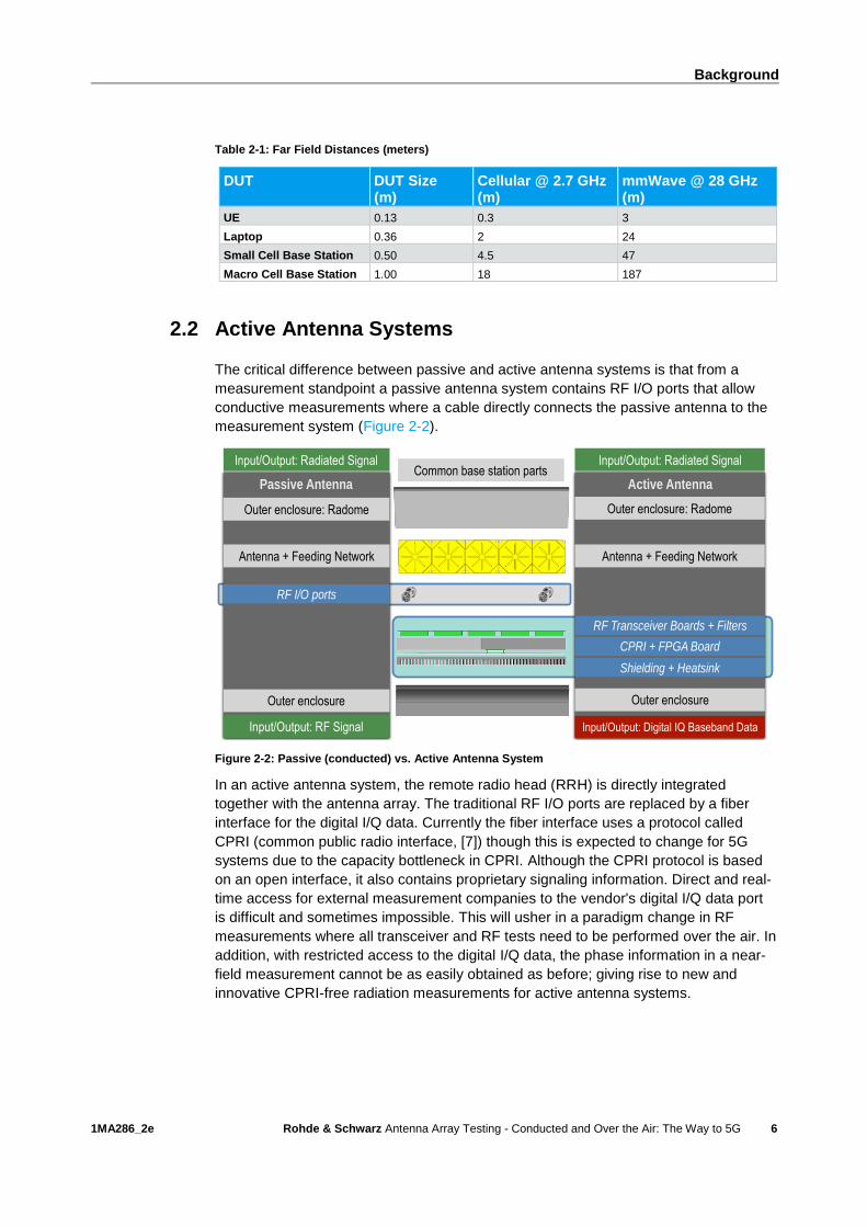
Table 2-1 lists the distances of the boundary between near and far fields for different
devices (UE terminal equipment and basestations) for both traditional cellular
frequencies and the new millimeter wave (mmWave) frequencies being considered for
5G. For lower frequencies and smaller devices, it is possible to measure in the far-field
region, consequently only requiring a magnitude or power measurement. In the
mmWave region, the size of the device dominates over the smaller wavelength and it
becomes impractical to measure in the far field for anything larger than a small device
under test (DUT).
Basestation 8 Element Array at 2.7 GHz
Radiated Near Field Region Phase & Magnitude
2D 2 / l = 4.5 m0.62 D 3 / l = 0.6 m
Reactive Near Field Region (< 0.6m)
Antenna Aperture: D = 0.5 m
Far Field Magnitude
Reactive Near Field Region
D
Background
1MA286_2e Rohde & Schwarz Antenna Array Testing - Conducted and Over the Air: The Way to 5G
6
Table 2-1: Far Field Distances (meters)
DUT DUT Size (m)
Cellular @ 2.7 GHz (m)
mmWave @ 28 GHz (m)
UE 0.13 0.3 3
Laptop 0.36 2 24
Small Cell Base Station 0.50 4.5 47
Macro Cell Base Station 1.00 18 187
2.2 Active Antenna Systems
The critical difference between passive and active antenna systems is that from a
measurement standpoint a passive antenna system contains RF I/O ports that allow
conductive measurements where a cable directly connects the passive antenna to the
measurement system (Figure 2-2).
Figure 2-2: Passive (conducted) vs. Active Antenna System
In an active antenna system, the remote radio head (RRH) is directly integrated
together with the antenna array. The traditional RF I/O ports are replaced by a fiber
interface for the digital I/Q data. Currently the fiber interface uses a protocol called
CPRI (common public radio interface, [7]) though this is expected to change for 5G
systems due to the capacity bottleneck in CPRI. Although the CPRI protocol is based
on an open interface, it also contains proprietary signaling information. Direct and real-
time access for external measurement companies to the vendor's digital I/Q data port
is difficult and sometimes impossible. This will usher in a paradigm change in RF
measurements where all transceiver and RF tests need to be performed over the air. In
addition, with restricted access to the digital I/Q data, the phase information in a near-
field measurement cannot be as easily obtained as before; giving rise to new and
innovative CPRI-free radiation measurements for active antenna systems.
Passive Antenna Active Antenna
Outer enclosure: Radome
Antenna + Feeding Network
Outer enclosure
RF I/O ports
Outer enclosure: Radome
Antenna + Feeding Network
Outer enclosure
RF Transceiver Boards + Filters
Shielding + Heatsink
CPRI + FPGA Board
Input/Output: Radiated Signal
Input/Output: RF Signal Input/Output: Digital IQ Baseband Data
Input/Output: Radiated SignalCommon base station parts

Background
1MA286_2e Rohde & Schwarz Antenna Array Testing - Conducted and Over the Air: The Way to 5G
7
2.3 Antenna Arrays
It is desirable for an antenna system to be able to focus its energy in a particular
direction in order to maximize the signal power towards a particular device. Using a
half-wavelength dipole as an example, the gain can be increased using two methods
(Figure 2-3):
● Antenna aperture: By increasing the aperture (or size of the antenna), the larger
antenna becomes more directive due to the periodic current distribution across the
antenna. Although this method does not require external circuitry for control, the
direction of the beam is fixed and the number of sidelobes increases. Examples
include electrically long dipoles, horns, and waveguides.
● Antenna array: If the single dipole element is instead repeated according to the
periodicity of the current distribution, an antenna array is created. The amplitude
and phase of the signals to individual elements can be adjusted to control both the
beam direction and sidelobe levels, creating a “phased array”. This results in a
significantly more complex feeding network with higher losses than the first
method. Examples include RADAR for automotive, aircraft, ships, and satellites.
Figure 2-3: Antenna Arrays
Figure 2-4 illustrates the basic mechanism of a phased antenna array with M antenna
elements. The antenna elements are usually separated by a distance of half-
wavelength in order to minimize mutual coupling. Larger separations result in higher
grating lobes. In order to form a beam pointed in a particular direction of θ, the phase
differences between antennas are set to particular values. Figure 2-5 shows that by
setting a 90 degree phase difference between 8 dipoles separated by half-length, then
the beam direction is steered 30 degrees. The resulting main beam has a 0.5 degree
broader 3 dB beamwidth and a reduction of peak gain by 0.5 dB.
l = 5λ/2
Single Element Antenna Array
Five λ/2 antennas
Phased Array
Feeding Network

Background
1MA286_2e Rohde & Schwarz Antenna Array Testing - Conducted and Over the Air: The Way to 5G
8
Figure 2-4: Phased Antenna Array
The beam steering capabilities of an antenna array can create both a high gain beam
towards a specific direction as well as creating a null in a specific direction in order to
mitigate interference in a MU-MIMO system. Therefore, in addition to phase shifting,
weighting of the signal amplitude is applied to reduce the side lobes (Figure 2-5). For
example, a symmetric linear tapering of the signal amplitudes in the array results in
sidelobes that are 10 dB to 15 dB lower, but in a broader beamwidth of the main lobe
(5 degree increase).
Figure 2-5: Phase and Amplitude Weighting for Antenna Arrays (simulated using CST Microwave
Studio)
. . .
. . .
. . .Phase Shifters
Attenuators
Antennas
To far-field
d
Broadside
θ
φ1 φ2 φ3
φM
Df =2p
ldsinq

Background
1MA286_2e Rohde & Schwarz Antenna Array Testing - Conducted and Over the Air: The Way to 5G
9
2.4 Beamforming Architectures
Figure 2-6: Beamforming Architectures for Active Antenna Systems
There are three types of beamforming architectures used for antenna arrays (Figure
2-6):
● Analog beamforming (ABF): The traditional way to form beams is to use
attenuators and phase shifters as part of the analogue RF circuit where a single
data stream is divided into separate paths. The advantage of this method is that
there is only one RF chain (PA, LNA, filters, switch/circulator) required. The
disadvantage is the loss from the cascaded phase shifters at high power.
● Digital beamforming (DBF): Digital beamforming assumes there is a separate RF
chain for each antenna element. The beam is then "formed" by matrix-type
operations in the baseband where artificial amplitude and phase weighting is
performed. For frequencies lower than 6 GHz, this is the preferred method since
the RF chain components are comparatively inexpensive and can combine MIMO
and beamforming into a single array. For frequencies of 28 GHz and above, the
PAs and ADCs are very lossy for standard CMOS components. If exotic materials,
such as gallium arsenide and gallium nitrate are used, the losses decrease at the
expense of high cost.
● Hybrid beamforming (HBF): Hybrid beamforming combines digital beamforming
with analog beamforming in order to allow the flexibility of MIMO plus beamforming
while reducing the cost and losses of the beamforming unit (BFU). Each data
stream has its own separate analog BFU with a set of M antennas. If there are N
data streams, then there are NxM antennas. The analog BFU loss due to phase
shifters can be mitigated by replacing the adaptive phase shifters with a selective
beamformer such as a Butler matrix. One proposed architecture uses the digital
BFU to steer the direction of the main beam while the analog BFU steers the beam
within the digital envelop (Figure 2-7).
Analog Beamforming (ABF)
PAx(t) ...
ABF
Phase shifters
N = 1
Ant 1
Ant M
...
N = 1, M Antennas
Digital Beamforming (DBF)
N TRx = M Antennas
...
TRx 1 Ant 1
Ant M
PA
PA
DBF
Baseband Beam-
formingTRx N
x1(t)
xN(t)
... ...
...
Hybrid Beamforming (HBF)
N < M
...
TRx 1 Ant 1
Ant M
PA
PA
DBF
Baseband Beam-
formingTRx N
x1(t)
xN(t)
...
...
ABF 1
Ant p
...
Ant q
...
ABF N
From Analog .... ... To Digital … ... To Hybrid

Background
1MA286_2e Rohde & Schwarz Antenna Array Testing - Conducted and Over the Air: The Way to 5G
10
Figure 2-7: Comparison between Analog, Digital, and Hybrid Beamforming [10]
2.5 Array Calibration
Figure 2-8: Static and dynamic tolerances in antenna arrays
Due to the sensitivity of the antenna array beamsteering to the phase differences
between the antenna elements, each array must be calibrated for the following
tolerances (Figure 2-8):
● Phase: Phase error can have a large effect on the antenna beam depending on its
statistical properties. If the phase error is uniformly distributed across the array,
then the main beam direction does not change. Instead, the nulls that are often
used to block interference are severely affected, losing 10 dB to 20 dB. If there is a
more deterministic phase error distribution, then this will steer the beam in a
different direction. Phase error can be caused by manufacturing tolerances in the
RF feeding network, thermal effects in the PAs and LNAs, and group delay
Phase/Magnitude/Frequency Tolerances (Static & Dynamic)
RFIC RFIC
LOFPGA
Digital IQ
RF Feeding Network
Dynamic Thermal Effects in PAs
Timing Errors in ADCs
Frequency Drift Between Modules
General Manufacturing Tolerances of
Components & Thermal Effects
Phase Shifter Tolerances
Group Delay Variations

Background
1MA286_2e Rohde & Schwarz Antenna Array Testing - Conducted and Over the Air: The Way to 5G
11
variations in the filters. It is recommended to keep the phase error between
antenna elements below ±5° (commercial specification for AAS).
● Amplitude: Amplitude error does not affect the direction of the beam, but rather the
peak gain and the sidelobe levels and is generally due to the thermal effects on the
active components (PA and LNA). Recommended error should be below ±0.5 dB
(commercial specification for AAS).
● Timing/Frequency: Depending on the circuit architecture, if a common LO network
is not used between modules, there will be frequency drift in addition to the timing
errors in the ADCs. Recommended level of frequency drift is 0.5 ppm (commercial
specification for AAS).
2.6 Development Process of an Antenna Array
Figure 2-9 shows the simplified typical product development process of an antenna
array for an infrastructure supplier. The different phases in this product development
process require different measurement and verification methods, thereby using various
approaches to measure a Massive MIMO system will require different test interfaces to
both the complete antenna array and individual antenna elements.
Figure 2-9: Product development process of an antenna array
Antenna arrays with 64 or more elements (corresponding to an 8x8 cross-polarized
antenna array) may not provide any individual antenna connectors in the final
assembly. In earlier phases of the product design, however, antenna elements are
typically accessible with connectors to verify the S-parameters of individual antennas.
Verification and qualification of antenna arrays is required in all product development
process phases from initial R&D design to final production test. Mutual coupling (S21)
between antenna elements has an adverse effect on network capacity. Therefore
simultaneous multiport passive (conducted) measurements for accurate
characterization are required.

Conducted Antenna Measurements
1MA286_2e Rohde & Schwarz Antenna Array Testing - Conducted and Over the Air: The Way to 5G
12
3 Conducted Antenna Measurements
In the design phase, when antenna connectors are still accessible, a vector network
analyzer is used as described in Section 3.1. The VNA, together with a switch matrix,
can be used to measure the S-parameters of antenna arrays up to 288 elements.
3.1 Measurements using Vector Network Analyzers
For antenna arrays, the most common measurement with a vector network analyzer
are the S-parameter measurements (both transmission and reflection coefficients). The
S-parameters contain magnitude and phase information which can be used to measure
both near-field and far-field quantities.
ı Reflection coefficient: = S11 = b1/a1 (reflected power at antenna 1 / injected
power at antenna 1)
ı Transmission coefficient: = S21 = b2/a1 (transmitted power at antenna 2 /
injected power at antenna 1)
Figure 3-1: Planar antenna array DUT of 64 elements & Mutual coupling between array elements
An example of an antenna array is shown in Figure 3-1 with 64 dual-polarized
antennas and 128 antenna ports. Due to the high number of ports, connecting cables
and subsequent calibration of the VNA is difficult and time consuming. There are two
methods to measure the S-parameters of this array:
1. VNA with two or four ports and a switch matrix
The VNA is attached to a switch matrix that is connected to the DUT. This
method, however, can only measure two to four simultaneous ports. This is not
enough ports to accurately measure the total mutual coupling (one antenna
element has eight co-polarized neighbors and 17 co-/cross-polarized neighbors).
AAS Square Array Mutual Coupling: 8 Adjacent Dual Polarized Antenna Neighbors
17 Adjacent Antenna Feeds

Conducted Antenna Measurements
1MA286_2e Rohde & Schwarz Antenna Array Testing - Conducted and Over the Air: The Way to 5G
13
2. Multiport VNA with multiple ports
Multiport VNAs simultaneously measure all ports in order to reduce the test
duration and perform a complete mutual coupling measurement between one
antenna element and its surrounding neighbors. If the number of antenna
elements is higher than the number of simultaneous ports (e.g. higher than 24 for
the R&S®ZNBT8), switch matrixes can also be added. An additional benefit is that
specific tests like “active return loss” (S11, S22, S33, …, S2424) can be measured in
parallel with many ports stimulated simultaneously. This method provides deeper
insights into antenna array in the design phase which has an effect on the real
world operation case in terms of network capacity.
Figure 3-2 illustrates the effect of antenna mutual coupling on the capacity of the cell.
Comparing a uniform linear array (ULA) with a uniform square array (USA), it is shown
that the element spacing between elements on a USA needs to be three times greater
than between elements on a ULA to maintain the same network capacity.
Figure 3-2: Network capacity as a function of mutual coupling [8]
3.2 R&S Solutions for Conducted Measurements
Vector network analyzers from Rohde & Schwarz offer optimum performance and
functionality for use in antenna measurement systems with a wide range of solutions
for multiport network analysis. The solutions are flexible, allowing for the choice of
either a true multiport vector network analyzer or a switched-matrix solution (optional
R&S switch matrices) as summarized in Table 3-1.
Table 3-1: R&S Multiport Vector Network Analyzers
R&S Vector Network Analyzer
Frequency Range (model dependent)
Number of Ports Maximum Ports with Switch Matrix
R&S®ZVA 300 kHz to 110 GHz Up to 4 Custom Solutions
R&S®ZNB 9 kHz to 40 GHz 2 or 4 48 with R&S®ZN-Z84
12 with R&S®ZN-Z85
R&S®ZNBT8 9 kHz to 8.5 GHz 4 to 24 (in groups of 4) 288 with R&S®ZN-Z84
R&S®ZNBT20 100 kHz to 20 GHz 8 to 16 (in groups of 4) 48 with R&S®ZN-Z85
Antenna Spacing (λ)
Capacity (bits/c
hannel)
6
5
4
3
2
1
0.5 1 1.5 2 2.5
Array Type Affects Capacity
Perfect Conditions
Normal BTx: ULA
5G AAS: USA
Unifo
rm L
ine
ar
Arr
ay (
UL
A)
Uniform Square Array (USA)

Over-the-Air (OTA) Antenna Measurements
1MA286_2e Rohde & Schwarz Antenna Array Testing - Conducted and Over the Air: The Way to 5G
14
4 Over-the-Air (OTA) Antenna Measurements
An antenna array applying massive MIMO in both the sub-6 GHz and mmWave
frequency range will not provide antenna connectors due to added complexity and
cost, physical size limitations, and resulting insertion loss. Consequently, OTA tests
are required. OTA tests measuring the three-dimensional antenna pattern can be
performed either in near field or in far field. Measurements in near field allow smaller
anechoic chambers for the measurement, but require an additional near-field to far-
field transformation for antenna gain patterns. Section 4.1 describes the status of
3GPP standardization with respect to OTA tests of Active Antenna Systems (AAS).
OTA measurement parameters can be divided into two general categories: R&D for
more complete investigation of the DUT radiated properties, and production for
calibration, verification, and functional testing as summarized below:
● R&D Measurements
– Gain patterns: Gain patterns are either 2D from one of the three principal
planes (E1, E2, or H-plane) or a complete 3D pattern. For antenna arrays with
one or more beams, the 3D gain pattern is more useful (Figure 4-1). Additional
information on pattern characterization is available with [8] including an
example of a radiation pattern measurement at 28GHz.
– Radiated power: The effective radiated power (ERP) or effective isotropic
radiated power (EIRP) is used to measure an active antenna system either as
a UE or a basestation. For UE testing, total radiated power (TRP) is used
instead where TRP is the weighted integral of the ERP values over a sphere.
– Receiver sensitivity: Receiver sensitivity is characterized by the parameter
effective isotropic sensitivity (EIS) and measures the block error rate as a
function of the receive power equal to the specified receiver sensitivity.
– Transceiver and receiver characterization: Each individual transceiver in the
active antenna system needs to be verified through an OTA interface. This
includes a range of measurements for both the transmitter and the receiver as
listed in Table 4-1. It is assumed that each transceiver will turn on for individual
verification.
Table 4-1: Transceiver and receiver tests
Transmitter Test Receiver Test
Maximum Output Power Sensitivity
EVM Dynamic Range
ACLR Band Selection
Spurious Emissions Blocking (IBB, OOB, NBB)
Intermodulation Adjacent Channel Selectivity
– Beam steering & beam tracking: Due to the high path loss and limited range of
a mmWave wireless system, precise beam tracking and fast beam acquisition
is required for mobile users. Whereas with antenna implementation for existing
cellular technologies static beam pattern characterization was sufficient,
mmWave systems will require dynamic beam measurement systems.

Over-the-Air (OTA) Antenna Measurements
1MA286_2e Rohde & Schwarz Antenna Array Testing - Conducted and Over the Air: The Way to 5G
15
● Production Testing
– Antenna/relative calibration: In order to accurately form beams, the phase
misalignment between RF signal paths needs to be below ±5°. This
measurement can be performed for both passive and active antenna systems
using either a phase-coherent receiver to measure the relative difference
between all antenna elements. This is then compiled into a lookup table for the
AAS to use as a reference for beam generation or to calibrate the internal self-
calibration circuits inside the AAS unit.
– Transceiver calibration: Due to the lack of RF ports on some Massive MIMO
systems, the individual transceivers will need to be calibrated using OTA
techniques. This includes both transmitters and receivers.
– Five point beam test: The AAS manufacturer specifies a reference beam
direction, maximum EIRP, and accordingly EIRP values for each declared
beam. For conformance the maximum EIRP point, and four additional points
corresponding to the most extreme steering positions are measured (as further
discussed in Section 4.1).
– Functional tests: This is the final test performed on the completely assembled
unit in production. It can consist of a simple radiated test, a five point beam
test, and aggregate transceiver functionality, such as an EVM measurement of
all transceivers.
Figure 4-1: Example 3D antenna pattern for a small antenna array (16 elements) at 2.1GHz
OTA measurement systems can be classified into three distinct types depending on
which part of the radiated field is being sampled (Figure 2-1). The field regions are
separated according to the power distribution of the electromagnetic field. In the
reactive near-field region, determining the power requires knowledge about magnitude
and phase of the electromagnetic field whereas the radiated field in the far-field region
allows determining power only based on the magnitude of the electromagnetic wave.
The region between these two extremes is the radiated near field where both the
phase and magnitude of the field need to be measured.
For small devices (in terms of wavelengths), such as UEs, the device size is small
enough such that the required chamber size for far-field conditions is dominated by the
measurement wavelength. For larger devices, such as base stations or Massive
MIMO, the required chamber size becomes very large. Huygen’s principle in

Over-the-Air (OTA) Antenna Measurements
1MA286_2e Rohde & Schwarz Antenna Array Testing - Conducted and Over the Air: The Way to 5G
16
electromagnetics states that if the tangential electric and magnetic fields are known on
an arbitrary surface enclosing the antenna, then the equivalent far-field radiation
properties can be calculated using Fourier transforms. Chamber sizes can be reduced
significantly as long as the measurement system accurately samples the phase and
magnitude of the electromagnetic field on the entire enclosing surface.
Figure 4-2: Types of OTA Measurement Systems
Most measurements take place either in the radiated near field or in the far field of the
DUT due to the difficulty in measuring the reactive near field without coupling to the
DUT as summarized below and in Figure 4-2:
● Far field
– Far-field chamber size: Measuring in the far-field region only requires a direct
measurement of the field magnitude of the plane waves. Such chambers are
generally quite large where the length is set by a combination of the DUT size
and the measurement frequencies.
– Near-field chamber size: Although the far field is generally measured at a
suitable distance from the DUT, it is possible to manipulate the
electromagnetic fields such that a near-field chamber can be used to directly
measure the plane wave magnitudes. There are two possible techniques:
i) Compact range chambers: The simplest method to form a planar wave at
the surface of the DUT is to extend the path of the electromagnetic fields
by using reflectors, similar to optical reflectors. Due to the expense in
constructing accurate reflectors, this technique is used mostly for large
DUTs such as aircrafts and satellites.
ii) Plane Wave Converter (PWC): A second method to create a planar wave
at the DUT is to replace the measurement antenna with an antenna array.
Similar to using lenses in an optics system, the antenna array can
generate a planar far field at a targeted zone in the region of the DUT
(Figure 4-3).

Over-the-Air (OTA) Antenna Measurements
1MA286_2e Rohde & Schwarz Antenna Array Testing - Conducted and Over the Air: The Way to 5G
17
Figure 4-3: Plane Wave Converter 3GPP Submission
● Radiated near field: Measurements in the near-field region require both the field
phase and magnitude sampled over an enclosed surface (spherical, linear, or
cylindrical) in order to calculate the field magnitude using Fourier spectral
transforms.
This measurement is usually performed using a vector network analyzer with one
port at the DUT and the other port at the measurement antenna. For active
antennas or Massive MIMO, there are often no dedicated antenna or RF ports, so
the OTA measurement system must be able to retrieve the phase in order to
complete the transformation into far field. There are two methods of performing
phase-retrieval for active antenna systems (Figure 4-4):
– Interferometric: This method uses a second antenna with a known phase used
as a reference. The reference signal is mixed with the DUT signal with
unknown phase. Using post-processing, the phase of the DUT signal can be
extracted and used for the near-field to far-field transformation.
– Multiple surfaces or probes: Instead of using a second antenna for the phase
reference, this method uses a second surface volume as the phase reference
with at least one wavelength separation between the two measurement radii.
As an alternative to the measurement of multiple surfaces, two probes with
different antenna field characteristics can be used instead over a single
measurement surface. The two probes need to be separated by at least half-
wavelength to minimize mutual coupling.
3GPP TSG-RAN WG4 Meeting #78 R4-161372
Over-the-Air (OTA) Antenna Measurements
1MA286_2e Rohde & Schwarz Antenna Array Testing - Conducted and Over the Air: The Way to 5G
18
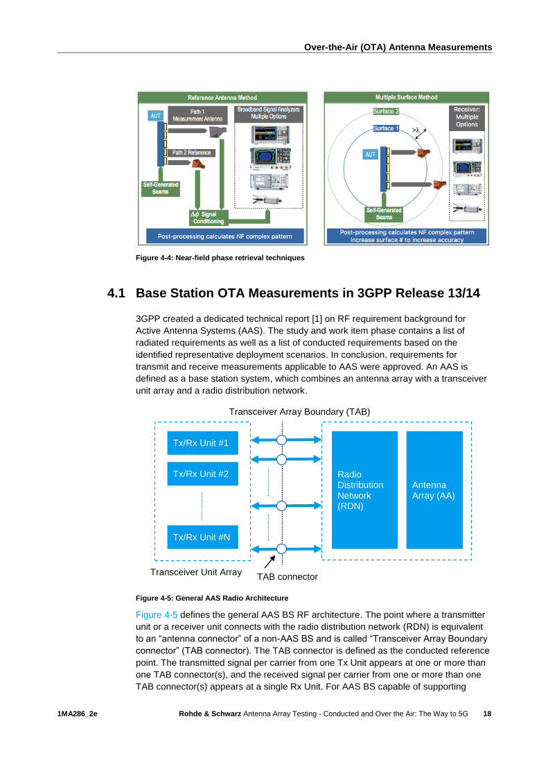
Figure 4-4: Near-field phase retrieval techniques
4.1 Base Station OTA Measurements in 3GPP Release 13/14
3GPP created a dedicated technical report [1] on RF requirement background for
Active Antenna Systems (AAS). The study and work item phase contains a list of
radiated requirements as well as a list of conducted requirements based on the
identified representative deployment scenarios. In conclusion, requirements for
transmit and receive measurements applicable to AAS were approved. An AAS is
defined as a base station system, which combines an antenna array with a transceiver
unit array and a radio distribution network.
Figure 4-5: General AAS Radio Architecture
Figure 4-5 defines the general AAS BS RF architecture. The point where a transmitter
unit or a receiver unit connects with the radio distribution network (RDN) is equivalent
to an “antenna connector” of a non-AAS BS and is called “Transceiver Array Boundary
connector” (TAB connector). The TAB connector is defined as the conducted reference
point. The transmitted signal per carrier from one Tx Unit appears at one or more than
one TAB connector(s), and the received signal per carrier from one or more than one
TAB connector(s) appears at a single Rx Unit. For AAS BS capable of supporting
Tx/Rx Unit #1
Tx/Rx Unit #2
Tx/Rx Unit #N
Radio Distribution Network (RDN)
Antenna Array (AA)
Transceiver Array Boundary (TAB)
TAB connector Transceiver Unit Array

Over-the-Air (OTA) Antenna Measurements
1MA286_2e Rohde & Schwarz Antenna Array Testing - Conducted and Over the Air: The Way to 5G
19
applications employing beamforming, all or subgroups of TAB connectors can be
configured with designated amplitude and phase weights such that one or more beams
are radiated from the antenna array (analog, digital, or hybrid beamforming). Note that
from testing perspective requirements are defined with respect to a point of reference
in the far field.
4.1.1 Radiated Requirements
3GPP defines the OTA requirements in terms of electromagnetic and spatial
parameters. The electromagnetic parameters are specified either in terms of power
(dBm) or field strength (dBµV/m). The spatial parameters are specified in a Cartesian
coordinate system (x, y, z) using spherical coordinates (r, θ, ɸ), see Figure 4-6.
Figure 4-6: Orthogonal representation of coordinate system
The chosen method requires the manufacturer to declare the number of beams
intended for cell-wide coverage. Requirements are then to be verified per declared
beam. The vendor declares the location of the coordinate system origin in reference to
an identifiable physical feature of the AAS BS enclosure. A few basic definitions apply:
The declared beam direction pair is associated with the beam center direction and a
beam peak direction. A beam center direction and a beam peak direction characterize
the capability of the AAS to create a beam. The center direction equals to the
geometric center of the -3 dB EIRP contour of the beam. The beam peak direction is
the direction where the maximum EIRP is to be found (Figure 4-7).
Figure 4-7: Examples of beam direction pairs (left: peak at the 3dB contour center, right: peak not at
the 3dB contour center)
z
y
x
ɸ
θ
Beam center
direction and
beam peak
direction
Beam peak
direction Beam center
direction
x
Over-the-Air (OTA) Antenna Measurements
1MA286_2e Rohde & Schwarz Antenna Array Testing - Conducted and Over the Air: The Way to 5G
20
The reference beam direction is the declared beam direction pair achieving the
intended maximum EIRP. The beamwidth of a beam is defined as the angles
describing the major and minor axes of an ellipsoid closest fit to an essentially elliptic
half-power contour of the beam. Each beam supported is defined with a unique beam
identifier. With respect to characterizing each supported single beam, the manufacturer
declares highest intended EIRP including narrowest and widest intended beamwidth in
both azimuth and elevation (θ, ɸ).
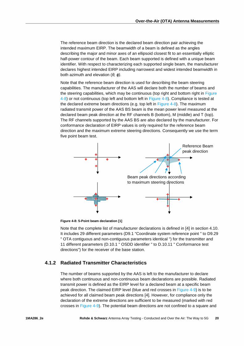
Note that the reference beam direction is used for describing the beam steering
capabilities. The manufacturer of the AAS will declare both the number of beams and
the steering capabilities, which may be continuous (top right and bottom right in Figure
4-8) or not continuous (top left and bottom left in Figure 4-8). Compliance is tested at
the declared extreme beam directions (e.g. top left in Figure 4-8). The maximum
radiated transmit power of the AAS BS beam is the mean power level measured at the
declared beam peak direction at the RF channels B (bottom), M (middle) and T (top).
The RF channels supported by the AAS BS are also declared by the manufacturer. For
conformance declaration of EIRP values is only required for the reference beam
direction and the maximum extreme steering directions. Consequently we use the term
five point beam test.
Figure 4-8: 5-Point beam declaration [1]
Note that the complete list of manufacturer declarations is defined in [4] in section 4.10.
It includes 29 different parameters (D9.1 "Coordinate system reference point " to D9.29
" OTA contiguous and non-contiguous parameters identical ") for the transmitter and
11 different parameters (D.10.1 " OSDD identifier " to D.10.11 " Conformance test
directions") for the receiver of the base station.
4.1.2 Radiated Transmitter Characteristics
The number of beams supported by the AAS is left to the manufacturer to declare
where both continuous and non-continuous beam declarations are possible. Radiated
transmit power is defined as the EIRP level for a declared beam at a specific beam
peak direction. The claimed EIRP level (blue and red crosses in Figure 4-9) is to be
achieved for all claimed beam peak directions [4]. However, for compliance only the
declaration of the extreme directions are sufficient to be measured (marked with red
crosses in Figure 4-9). The potential beam directions are not confined to a square and
Beam peak directions according
to maximum steering directions
Reference Beam
peak direction

Over-the-Air (OTA) Antenna Measurements
1MA286_2e Rohde & Schwarz Antenna Array Testing - Conducted and Over the Air: The Way to 5G
21
can be specified according to any arbitrary surface by the manufacturer. Those beam
directions that are compliant are included in the EIRP accuracy compliance
specifications.
Figure 4-9: Simplified example of AAS non-continuous beam declarations
The requirement defined in [4] reads
For each beam, the requirement is based on declarations (see table 4.10-1) of a beam
identifier (D9.3), reference beam direction pair (D9.7), rated beam EIRP at the beam's
reference direction pair (D9.8), EIRP accuracy directions set (D9.10), the beam
direction pairs at the maximum steering directions (D9.11) and their associated rated
beam EIRP (D9.12) and beamwidth(s) for reference beam direction pair and maximum
steering directions (D9.13).
And references the requirement defined in [2] including a specific accuracy as follows:
"For each declared beam, in normal conditions, for any specific beam peak direction
associated with a beam direction pair within the EIRP accuracy directions set , a
manufacturer claimed EIRP level in the corresponding beam peak direction shall be
achievable to within +2,2 dB and -2,2 dB of the claimed value."
Additionally [4] defines acceptable uncertainties of the test system according to Table
4-2. Consequently the requirement tested against during the test procedure comprises
the minimum requirement and this test uncertainty.
Table 4-2: Maximum Test System uncertainty for transmitter tests
Subclause Maximum Test System Uncertainty
Derivation of Test System Uncertainty
6.2 Radiated transmit power ±1.0 dB, f ≤ 3.0 GHz See 3GPP TR 37.842 [1], subclause 10.3.2.2. ±1.2 dB, 3.0 GHz < f ≤ 4.2 GHz
4.1.3 Radiated Receiver Characteristics
Similar to the power measurement in downlink direction, in uplink a sensitivity
requirement is defined based on the declaration of one or more OTA sensitivity
directions declarations (OSDD). The receiver is required to achieve a certain data
throughput at a particular OTA sensitivity power level.
The effective isotropic sensitivity (EIS) is defined as the power level relative to an
isotropic antenna that is incident on the AAS array from a specified azimuth/elevation
direction (angle of arrival) in order to meet the specified receiver sensitivity requirement
where the angle of arrival can be described as a combination of Φ and (Figure 4-10).
xx dBm

Over-the-Air (OTA) Antenna Measurements
1MA286_2e Rohde & Schwarz Antenna Array Testing - Conducted and Over the Air: The Way to 5G
22
The AAS may support multiple RoAoA (Range of Angles of Arrival), which describe the
overall redirection range capabilities of the antenna. For sensitivity testing the stimulus
signal is the same as the fixed reference measurement channel (FRC) for target
throughputs in non-AAS requirements [3]. The OTA sensitivity requirement applies per
polarization, under the assumption of polarization matching. It is up to the
manufacturer to declare whether or not dual polarization is supported by the AAS. As
in the downlink case, conformance is to be demonstrated at the extreme directions
marked with red crosses in Figure 4-10.
Figure 4-10: Five different directions of a sensitivity Range of Angles of Arrival (RoAoA - purple)
comprising the target redirection range (green contour) of an OSDD
The received signal level can be represented as a field-strength or EIS power level.
The relation between field-strength and EIS is [1]
2.77)(log20,, 10 fEEIS [dBm]
4.2 R&S Solutions for OTA Measurements
R&S has a wide selection of chambers, absorbers, measurement equipment, and
positioners as part of its integrated solutions for OTA measurements. The OTA
products range in size from benchtop systems to large anechoic chambers and with
measurement capabilities in frequency bands from 400 MHz to over 90 GHz.
Depending on the antenna array layout/design, there are two modes that require
different sets of measurement equipment (but can both use the same chamber,
absorbers, and positioner):
1. If the antenna system is passive (DUT has external RF ports for direct RF signal
transmission and reception) use a vector network analyzer with one port at the
DUT and the other ports for measurement antennas. Rohde & Schwarz offer two-
or four port network analyzers such as the R&S®ZVA, R&S®ZNB and R&S®ZNC.
Additionally multiport network analyzers such as the R&S®ZNBT and R&S®ZVT
are available.
2. If the system comprises of a remote radio head integrated together with an
antenna array with no external RF ports (AAS) perform an active antenna
measurement with a combination of a vector signal generator R&S®SMW200A or
R&S®SMBV100A and a signal and spectrum analyzer R&S®FSW or R&S®FSVA.
Φ
Fixed Reference Channel
at sensitivity level
Throughput
OSDD
RoAoA
Receiver target reference
direction for declared OSDD

Over-the-Air (OTA) Antenna Measurements
1MA286_2e Rohde & Schwarz Antenna Array Testing - Conducted and Over the Air: The Way to 5G
23
There are four types of R&S products for OTA for both passive and active antenna
systems:
ı Compliance Systems (R&S®TS8991): These include a series of turnkey solutions
for OTA measurements of UEs compliant to CTIA, 3GPP, and other wireless
standards and test cases, using far-field measurement techniques; see Table 4-3.
Table 4-3: Wireless Performance Test Chamber (WPTC) Turn-key Solutions
Specification DST200 WPTC XS WPTS S WPTC M WPTC L WPTC XL
Application UE UE, Small DUT
UE, Small DUT
UE, Medium DUT
UE, Large DUT
UE, Large DUT
Dimensions (L x W x H)
77x70x76cm 2.4x2.4x2.4m 3.5x3.0x3.0m 4.6x3.7x3.45m 5.2x4.3x4m 5.8x5.2x5.2m
Frequency Range (GHz)
0.7-6; 6-90 (ver2)
0.7-18 0.7-18 0.7-18 0.4-18 0.4-18
Range Length 30 cm 62 cm 102 cm 130 cm 138 cm 183 cm
CTIA Compliant No No No Yes Yes Yes
CTIA Test Cases (BH, HHH)
No Yes Yes Yes Yes Yes
ı R&S spiral scanner: The spiral scan can be used for both near-field and far-field
measurements. Traditional near-field measurements use a single probe stepping
through a uniform grid (typically on a spherical or cylindrical surface). This
approach results in long measurement times for higher frequencies (smaller grid
spacing in order to have sufficient samples) with almost 3 hours to measure a
DUT at 6 GHz. The speed can be improved by distributing the probes across an
arc for a spherical system or along a line for a rectilinear system. While this can
significantly reduce measurement times, the use of multiple probes introduces two
new problems: increased calibration times and mutual-coupling effects between
probes.
R&S combines two new technologies into its near-field scanner system in order to
address the problems of speed, calibration, and mutual coupling: Fast Irregular
Antenna Field Transformation Algorithm (FIAFTA) and the spiral scan. FIAFTA is
a new near-field to far-field transformation that allows the use of arbitrary grids
instead of uniform grids in the OTA measurement system. Figure 4-11 shows the
algorithm accuracy of a FIAFTA near-field measurement compared to a far-field
measurement in an accredited external laboratory.
Figure 4-11: FIAFTA Near-field accuracy COMPANY
RESTRICTED
FIAFTA Algorithm Accuracy
R&S Test Chamber External Accredited Lab Difference
Gain IEEE [dBi] 16.16 16.36 ± 0.12 -0.2
7

Over-the-Air (OTA) Antenna Measurements
1MA286_2e Rohde & Schwarz Antenna Array Testing - Conducted and Over the Air: The Way to 5G
24
The near-field scanner has a single dual-polarized probe (faster calibration and no
mutual coupling) that rotates along the measurement surface at the same time as
the DUT rotates at a faster speed. This combination of two rotating axes results in
a spiral scan that reduces the measurement time for a DUT at 6 GHz to below 6
minutes (Figure 4-12).
Figure 4-12: R&S spiral scanner
● Benchtop chambers & probes: Benchtop chambers are often used for rapid
antenna design and prototyping. R&S offers two benchtop systems for small DUTs
that can either measure the 3D beam pattern in a passive or active antenna
system or measure the real-time beam steering and beam acquisition capability of
the DUT. In a production line, the emphasis shifts from comprehensive DUT
analysis to calibration and faster functional testing. R&S production verification
systems are based on benchtop systems with some customization for specific
measurements. A functional test to measure the entire AAS unit can consist of
beam-pattern verification using the five point 3GPP method and/or simultaneous
excitation of the transceivers for joint transmitter or receiver tests (subset of the
test items listed in Table 4-1). For production, it is expected that the 5G DUTs will
follow a multi-step process for calibration and verification performed within the
near-field region of the DUT in Figure 2-1.
▪ R&S®DST200: This is the larger of the two benchtop systems with a size of
770 mm x 760 mm x 695 mm that can measure the 3D radiation patterns of
UE-sized devices from 1 GHz to 77 GHz (Figure 4-13). There is a space at
the top of the box to insert the measurement antenna (either horn or an R&S
wide-band Vivaldi antenna). The shielding effectiveness is over 100 dB for
frequencies below 18 GHz and over 75 dB up to 77 GHz. Automated
positioners allow a two-axis rotation of the DUT. The DST200 has many
applications and is used for automotive radar and 5G (both sub-6 GHz and
mmWave). It can also be used for antenna and transceiver calibration
measurements in production lines (as described in more detail below).
Uniform Grid Spiral Scan
3.8 GHz
0.6 x 0.6 m
6.0 GHz
radius 0.45 m
Grid Spiral Scan Spiral Scan
Angular resolution 5° 3°
Measurement time 2:45 min 5:30 min
Improvement (vs. Uniform grid)
32 times faster 40 times faster
R&S Near field Spiral Scanner

Over-the-Air (OTA) Antenna Measurements
1MA286_2e Rohde & Schwarz Antenna Array Testing - Conducted and Over the Air: The Way to 5G
25
Figure 4-13: R&S®DST200 Benchtop 3D Radiation Pattern System
▪ R&S®TS7124: This chamber is smaller compared to the R&S®DST200 with a
size of 450 mm x 400 mm x 480 mm. It is designed as a rack-mountable
solution (19” rack integration) with both an automatic pneumatic version for
production lines and a manual version for R&D measurements. It supports a
wide frequency range, providing shielding effectiveness of over 65 dB up to
67 GHz. This shielded box is designed such that the DUT is surrounded by
several stationary measurement antennas or probes (see Figure 4-14). A
typical setup places probes surrounding the DUT in order to perform and
monitor real-time beam steering and beam tracking for devices in the
mmWave region. Alternatively, the shielded box can be used at lower
frequencies for UE functional testing in production lines.
▪ R&S®NRPM: At higher frequencies in the mmWave region, received signals
suffer from high attenuation, and the measurement system becomes very
sensitive to mechanical arrangements, requiring frequent calibrations of the
system. R&S has an option to replace the antennas with OTA power sensor
probes (R&S®NRPM OTA power measurement solution). By placing the
power sensor diode directly on the wide-band Vivaldi antenna, the system
only requires a low frequency cable between the measurement probe
(R&S®NRPM-A66) and the power meter, thereby alleviating the attenuation
and frequent calibration issues for mmWave measurements.

Over-the-Air (OTA) Antenna Measurements
1MA286_2e Rohde & Schwarz Antenna Array Testing - Conducted and Over the Air: The Way to 5G
26
Figure 4-14: R&S®NRPM OTA power measurement solution & R&S®TS7124
Conclusion
1MA286_2e Rohde & Schwarz Antenna Array Testing - Conducted and Over the Air: The Way to 5G
27
5 Conclusion
In summary, due to the elimination of RF test ports and the use of frequencies in the
centimeter and millimeter wave length region, OTA will become an essential tool for
characterizing the performance of not just the antenna arrays of an Active Antenna
System of a Massive MIMO array, but the internal transceivers as well. For this reason
there will be a high demand for OTA chambers and measurement equipment to not
only measure the strict radiative properties of antennas, but substituting traditional
conducted transceiver measurements as well. Rohde & Schwarz with its wide range of
anechoic chambers and measurement equipment expertise is well situated to deliver
solutions even for future customer requirements.

Literature
1MA286_2e Rohde & Schwarz Antenna Array Testing - Conducted and Over the Air: The Way to 5G
28
6 Literature
[1] 3GPP TR 37.842 v13.1.0 TSG RAN E-UTRA and UTRA; Radio Frequency (RF)
requirement background for Active Antenna System (AAS) Base Station (BS). -
2016.
[2] 3GPP TS 36.105 v13.3.0 TSG RAN Active Antenna System (AAS) Base Station
(BS) transmission and reception.
[3] 3GPP TS 36.141 v13.3.0 TSG RAN E-UTRA; Base Station (BS) conformance
testing. - 2016.
[4] 3GPP TS 37.145-2 v. 13.1.0 TSG RAN; Active Antenna System (AAS) Base
Station (BS) conformance testing; Part 2: radiated conformance testing. - 2016.
[5] Balanis Constantine Antenna Theory: Analysis & Design [Book]. - New Jersey :
John Wiley & Sons, 2005.
[6] China Mobile Research Institute C-RAN: The Road Towards Green RAN //
Whitepaper. - 2013.
[7] Ericsson AB, Huawei Technologies Co. Ltd, NEC Corporation, Alcatel
Lucent and Nokia Networks CPRI Specification V7.0 (2015-10-09) [Report]. -
[s.l.] : www.CPRI.info, 2015.
[8] F. Rusek et al Scaling Up MIMO: Opportunities and Challenges with Very Large
Arrays [Journal]. - 2013. - Vols. IEEE Signal Processing Magazine, vol. 30, no.
1.
[9] Lloyd, Reil Millimeter-Wave Beamforming: Antenna Arrays and Characterization
(1MA276). - 2016.
[10] Shuangfeng Han et al Large-Scale Antenna Systems with Hybrid Analog and
Digital Beamforming for Millimeter Wave 5G [Journal] // IEEE Communications
Magazine. - 2015.

Ordering Information
1MA286_2e Rohde & Schwarz Antenna Array Testing - Conducted and Over the Air: The Way to 5G
29
7 Ordering Information
Designation Type Order No.
Vector Network Analyzer R&S®ZVAx 1145.1110.xx
Vector Network Analyzer R&S®ZNBx 1311.6010.xx
Vector Network Analyzer R&S®ZNC 1311.6004.12
Vector Network Analyzer R&S®ZNBT8 1318.7006.24
Vector Network Analyzer R&S®ZNBT20 1332.9002.24
Vector Network Analyzer R&S®ZVT8 1300.0000.08
Vector Network Analyzer R&S®ZVT20 1300.0000.20
Switch matrix R&S®ZN-Z84 1319.4500.02
Switch matrix R&S®ZN-Z85 1326.4777.03
Vector Signal Generator R&S®SMW200A 1412.0000.02
Vector Signal Generator R&S®SMBV100A 1407.6004.02
Three-Channel Sensor Module R&S®NRPM3 1425.8563.02
Single-Polarized Antenna Module R&S®NRPM-A66 1425.8740.02
Signal and Spectrum Analyzer R&S®FSWxx 1312.8000.Kxx
Signal and Spectrum Analyzer R&S®FSVAxx 1321.3008.xx
OTA Performance Test System R&S®TS8991
RF Diagnostic Chamber R&S®DST200 1510.9047.02
RF Shielded Box R&S®TS7124M 1525.8564.xx
RF Shielded Box R&S®TS7124AS 1525.8587.xx
Rohde & Schwarz
The Rohde & Schwarz electronics group offers
innovative solutions in the following business fields:
test and measurement, broadcast and media, secure
communications, cybersecurity, radiomonitoring and
radiolocation. Founded more than 80 years ago, this
independent company has an extensive sales and
service network and is present in more than 70
countries.
The electronics group is among the world market
leaders in its established business fields. The
company is headquartered in Munich, Germany. It
also has regional headquarters in Singapore and
Columbia, Maryland, USA, to manage its operations
in these regions.
Regional contact
Europe, Africa, Middle East +49 89 4129 12345 [email protected] North America 1 888 TEST RSA (1 888 837 87 72) [email protected] Latin America +1 410 910 79 88 [email protected] Asia Pacific +65 65 13 04 88 [email protected]
China +86 800 810 82 28 |+86 400 650 58 96 [email protected]
Sustainable product design
ı Environmental compatibility and eco-footprint
ı Energy efficiency and low emissions
ı Longevity and optimized total cost of ownership
This white paper and the supplied programs may
only be used subject to the conditions of use set
forth in the download area of the Rohde & Schwarz
website.
R&S® is a registered trademark of Rohde & Schwarz GmbH & Co.
KG; Trade names are trademarks of the owners.
Rohde & Schwarz GmbH & Co. KG
Mühldorfstraße 15 | 81671 Munich, Germany
Phone + 49 89 4129 - 0 | Fax + 49 89 4129 – 13777
www.rohde-schwarz.com
PA
D-T
-M: 3573.7
380.0
2/0
2.0
5/E
N/