anti-skid braking system (abs)
TRANSCRIPT

ANTI-SKID BRAKINGSYSTEM (ABS) <4WD>

35C-2
For the items below, refer to GROUP35A.
SEALANTS
ON-VEHICLE SERVICEBrake Pedal Check and Adjustment
Stop Lamp Switch Inspection
Brake Booster Operating Test
Check Valve Operation Check
Brake Booster Vacuum Switch Check
Load Sensing Spring Length Check andAdjustment
Load Sensing Proportioning Valve FunctionTest
Front Disc Brake Rotor Check
Brake Lining Thickness Check
Brake Drum Inside Diameter Check
Brake Lining and Brake Drum ConnectionCheck
BRAKE PEDAL
LOAD SENSING PROPORTIONING VALVE
REAR DRUM BRAKE
For the items below, refer to GROUP35B.
ON-VEHICLE SERVICEBleeding
Disc Brake Pad Check and Replacement
Wheel Speed Sensor Output Voltage Check
Hydraulic Unit Check
Solenoid Valve Check
Motor Operation Check
Motor Relay and Valve Relay Continuity Check
Remedy for a Flat Battery
MASTER CYLINDER AND BRAKEBOOSTER
HYDRAULIC UNIT
ABS-ECU

ABS <4WD> – General Information 35C-3
GENERAL INFORMATION 35200010130
The ABS consists of wheel speed sensors, stoplamp switch hydraulic unit and the ABS-ECU. Ifa problem occurs in the system, the malfunctioningsystem can be identified by means of the diagnosisfunction, and the trouble symptom memory will notbe erased even if the ignition switch is turned to
OFF. (However, it will be erased if the battery isdisconnected.)In addition, reading of diagnosis codes and datalist and actuator of testing are possible using theMUT-II .
Items Specifications
Speed sensor Magnet coil type
Front rotor teeth 47
Rear rotor teeth 47
CONSTRUCTION DIAGRAM
NOTE*1: For R.H. drive vehicles, those parts are installed at the right side.*2: Diesel-powered vehicles – L.H. drive vehicles.*3: Except diesel-powered vehicles – L.H. drive vehicles.
12
3*1 4*1
5
6
7*18*1
9*2
10
11
12
13
14
9*3
6
5
6 5
1. ABS valve relay2. ABS motor relay3. ABS warning lamp4. Stop lamp switch5. Rotor6. Wheel speed sensor7. ABS-ECU
8. Diagnosis connector9. Hydraulic unit
10. G-sensor11. 4WD position detection switch12. Free wheel engage switch13. Rear differential lock-ECU14. 4WD indicator-ECU

ABS <4WD> – Service Specification/Lubricants/Special Tools35C-4
SERVICE SPECIFICATION 35200030143
Items Standard value Limit
Front disc brake pad thickness mm 10 2.0
G-sensor output voltage V When installed 2.4 – 2.6 –
When removed witharrow mark facingdown
3.4 – 3.6 –
LUBRICANTS 35200040030
Items Specified lubricant
Brake fluid DOT3 or DOT4
Brake piston seal Repair kit grease
Guide pin boot inner surfaces
Lock pin boot inner surfaces
Piston boot mounting grooves
Brake piston boot inner surfaces
Lock pin bush inner surfaces
Piston cup surface
SPECIAL TOOLS 35200060142
Tool Number Name Use
MB991502 MUT-II sub assembly For checking of ABS (Diagnosiscode display when using theMUT-II )
MB991529 ABS check harness For checking of ABS (Diagnosiscode display when using the ABSwarning lamp)
MB991348 Test harness set For checking of G-sensor
MB990964MB990520
Brake tool set Pushing-in of the brake piston

ABS <4WD> – Troubleshooting 35C-5
TROUBLESHOOTING 35101110143
STANDARD FLOW OF DIAGNOSTIC TROUBLESHOOTINGRefer to GROUP 00 – How to Use Troubleshooting/Inspection Service Points.
NOTES WITH REGARD TO DIAGNOSISThe phenomena listed in the following table are not abnormal.
Phenomenon Explanation of phenomenon
System check sound When starting the engine, a thudding sound can sometimes be heard coming from insidethe engine compartment, but this is because the system operation check is beingperformed, and is not an abnormality.
ABS operation sound 1. Sound of the motor inside the ABS hydraulic unit operation. (whine)2. Sound is the generated along with vibration of the brake pedal. (scraping)3. When ABS operates, sound is generated from the vehicle chassis due to repeated
brake application and release.(Thump: suspension; squeak: tyres)
ABS operation (Long braking distance)
For road surfaces such as snow-covered roads and gravel roads, the braking distance forvehicles with ABS can sometimes be longer than that for other vehicles. Accordingly, advisethe customer to drive safely on such roads by lowering the vehicle speed and not being toooverconfident.
Shock during systemoperation check
Shock may be felt when the brake pedal is depressed slightly at a low driving speed. Thisoccurs due to ABS operation check (check at a vehicle speed of 8 km/h after starting), anddoes not indicate any malfunction.
Diagnosis detection condition can vary depending on the diagnosis code.Make sure that checking requirements listed in the “Comment” are satisfied when checking the troublesymptom again.
DIAGNOSIS FUNCTION 35201120108
DIAGNOSIS CODES CHECKRead a diagnosis code by the MUT-II or ABS warning lamp.(Refer to GROUP 00 – How to Use Troubleshooting/InspectionService Points.)
ERASING DIAGNOSIS CODESRefer to GROUP 00 – How to Use Troubleshooting/InspectionService Points.

ABS <4WD> – Troubleshooting35C-6
INSPECTION CHART FOR DIAGNOSIS CODES 35201130163
Inspect according to the inspection chart that is appropriate for the malfunction code.
Diagnosiscode No.
Inspection item Diagnosis content Reference page
11 Front right wheel speed sensor Open or short circuit Refer to GROUP 35B – Troubleshooting.
12 Front left wheel speed sensor
13 Rear right wheel speed sensor
14 Rear left wheel speed sensor
15 Wheel speed sensor Abnormal output signal Refer to GROUP 35B – Troubleshooting.
16 Power supply system Refer to GROUP 35B – Troubleshooting.
21 Front right wheel speed sensor Abnormal Refer to GROUP 35B – Troubleshooting.
22 Front left wheel speed sensor
23 Rear right wheel speed sensor
24 Rear left wheel speed sensor
25 Free wheel engage switch 35C-7
26 4WD position detection switch 35C-8
27 Rear differential lock detection switch 35C-9
32 G-sensor system 35C-10
33 Stop lamp switch system Refer to GROUP 35B – Troubleshooting.
41 Front right solenoid valve Refer to GROUP 35B – Troubleshooting.
42 Front left solenoid valve
43 Rear solenoid valve
51 Valve relay Refer to GROUP 35B – Troubleshooting.
53 Motor relay, motor Refer to GROUP 35B – Troubleshooting.
63 ABS-ECU Refer to GROUP 35B – ABS-ECU.(Replace the ABS-ECU )
64(Re lace the ABS-ECU.)

ABS <4WD> – Troubleshooting 35C-7
INSPECTION PROCEDURE CLASSIFIED BY DIAGNOSIS CODESFor diagnosis code numbers other than those listed below, refer to GROUP 35B – Troubleshooting.
Code No. 25 Free wheel engage switch Probable causeABS-ECU determines that an open circuit exists in the free wheel engage switchsystem.
Malfunction of wiring harness or connector Malfunction of 4WD indicator-ECU Malfunction of ABS-ECU
Does the 4WD indicator lamp operatenormally?
No4WD indicator-ECU check. (Refer toGROUP 22 – 4WD indicator-ECU.)
NGReplace the 4WD indicator-ECU.
Yes
Measure at ABS-ECU connector C-64. Disconnect the connector and
measure at the harness side. Ignition switch ON Voltage between 45 and body earth
OK: System voltage <when in2WD> or 0 V <when in 4WD>
NGCheck the following connectors.C-64 and A-02
NGRepair
OK
Check trouble symptom.NG
Check the harness between free wheelengage switch and the ABS-ECU, andrepair if necessary.
OK
Check the following connector.C-64
NGRepair
OK
Check trouble symptom.NG
Replace the ABS-ECU.

ABS <4WD> – Troubleshooting35C-8
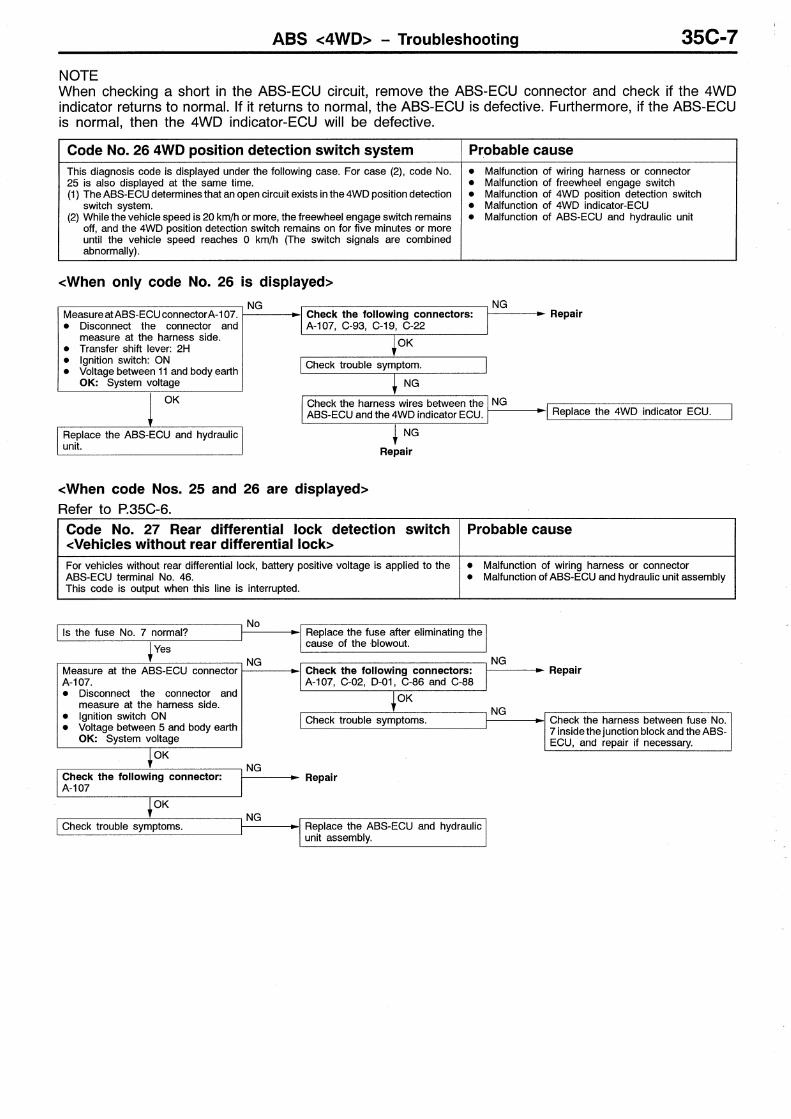
Code No. 26 4WD position detection switch Probable causeThis code is output at the following times:ABS-ECU determines that an open circuit exists in the 4WD detection switch system.The free wheel engage switch is off and the 4WD detection switch is on at a vehiclespeed of 15km/h or more for 5 seconds or more.
Malfunction of wiring harness or connector Malfunction of free wheel engage switch Malfunction of 4WD indicator-ECU Malfunction of 4WD position detection switch Malfunction of ABS-ECU
No
OK
Check trouble symptom.NG
Check the harnesses between 4WDposition detection switch and the ABS-ECU, and repair if necessary.
OKCheck the following connector.C-64
NGRepair
OK
Check trouble symptom.NG
Replace the ABS-ECU.
Yes
Measure at ABS-ECU connec-tor C-64. Disconnect the connector
and measure at the harnessside.
Ignition switch ON Transfer lever:2H Voltage between 35 and
body earthOK: System voltage
NGCheck the following connector.C-64
NGRepair
Does the 4WD indicator lamp operatenormally?
Trouble symptom Main cause Remedy
Even when the transfer shift lever isin the ”4H” position, the 4WD frontwheel indicator lamp does notilluminate.
Broken harness wire between the 4WDindicator-ECU and the free-wheelengage switch, or broken earth wirefrom the free wheel engage switch
Repair the harness.
Free wheel engage switch is defective. Replace the switch.
Even when the transfer shift lever isin the ”4H” position, the free wheeldifferential indicator lamp does notilluminate
Broken harness wire between the 4WDindicator-ECU and the 4WD positiondetection switch
Repair the harness.
illuminate.Broken wire in the 4WD indicator-ECUcircuit
4WD indicator-ECU inspection (Re-fer to GROUP 22 – 4WD indicator-ECU.)
Free wheel differential indicatorlamp illuminates regardless of theposition of the transfer shift lever
Short in the harness wire in the 4WDposition detection switch circuit
Repair the harness.
position of the transfer shift lever.4WD position detection switch isdefective.
Replace the switch.
Short in the ABS-ECU circuit Replace the ABS-ECU.
Short in the 4WD indicator-ECU circuit 4WD indicator-ECU inspection (Re-fer to GROUP 22 – 4WD indicator-ECU.)
No indicator is illuminated Power circuit in the 4WD indicator-ECUis defective.
Repair the harness.
4WD indicator-ECU is defective. 4WD indicator-ECU inspection (Re-fer to GROUP 22 – 4WD indicator-ECU.)
NOTEWhen checking a short in the ABS-ECU circuit, remove the ABS-ECU connector and check if the 4WDindicator returns to normal. If it returns to normal, the ABS-ECU is defective. Furthermore, if the ABS-ECUis normal, then the 4WD indicator-ECU will be defective.

ABS <4WD> – Troubleshooting 35C-9
Code No. 27 Rear differential lock detection switch<Vehicles with rear differential lock>
Probable cause
The ABS-ECU determines that an open circuit occurs in rear differential detectionswitch system.
Malfunction of wiring harness or connector Malfunction of rear differential lock-ECU Malfunction of ABS-ECU
Does the 4WD indicator lamp (rear dif-ferential lamp) operate normally?
NoRear differential lock-ECU check.
NGReplace the rear differential lock-ECU.
Yes
Measure at the ABS-ECU connectorC-64. Disconnect the connector and
measure at the harness side. Ignition switch: ON Rear differential lock switch: OFF Voltage between 46 and body earth
OK: System voltage
NGCheck the following connectors.C-88, C-86, C-02 and C-64
NGRepair
OK
Check trouble symptom.NG
Check the harness between rear differ-ential detection switch and the ABS-ECU, and repair if necessary.
OK
Check the following connector.C-64
NGRepair
OK
Check trouble symptoms.NG
Replace the ABS-ECU.
Code No. 27 Rear differential lock detection switch<Vehicles without rear differential lock>
Probable cause
For vehicles without rear differential lock, battery positive voltage is applied to theABS-ECU terminal No. 46.This code is output when this line is interrupted.
Malfunction of wiring harness or connector Malfunction of ABS-ECU
Is the fuse No. 7 normal?No
Replace the fuse after eliminating thecause of the blowout.Yes
Measure at the ABS-ECU connectorC-64. Disconnect the connector and
measure at the harness side. Ignition switch ON Voltage between 46 and body earth
OK: System voltage
NGCheck the following connectors.C-88, C-86, C-02 and C-64
NGRepair
OK
Check trouble symptoms.NG
Check the harness between fuse No.7 inside the junction block and the ABS-ECU, and repair if necessary.
OK
Check the following connector.C-64
NGRepair
OK
Check trouble symptoms.NG
Replace the ABS-ECU.

ABS <4WD> – Troubleshooting35C-10
Code No. 32 G-sensor system Probable causeThis code is output at the following times:The G-sensor output is less than 0.5 V or more than 4.5 V.An open or short circuit is present in the G-sensor system.
Malfunction of G-sensor Malfunction of wiring harness or connector Malfunction of ABS-ECU
G-sensor check (Refer to P. 35C-20.)NG
Replace the G-sensor.
OK
Measure at ABS-ECU connector C-62. Ignition switch ON Voltage between 4 and 17
OK: 2.4 – 2.6 V
NGCheck the following connector.C-02
NGRepair
OK
Check trouble symptom.NG
Check the harness between the G-sen-sor and the ABS-ECU, and repair if nec-essary.
OK
Check the following connector.C-62
NGRepair
OK
Check trouble symptom.
NG
Replace the ABS-ECU.
ABS WARNING LAMP INSPECTION 35201200086
Refer to GROUP 35B – Troubleshooting.
INSPECTION CHART FOR TROUBLE SYMPTOMS 35201140159
Refer to GROUP 35B – Troubleshooting.
ABS <4WD> – Troubleshooting 35C-11
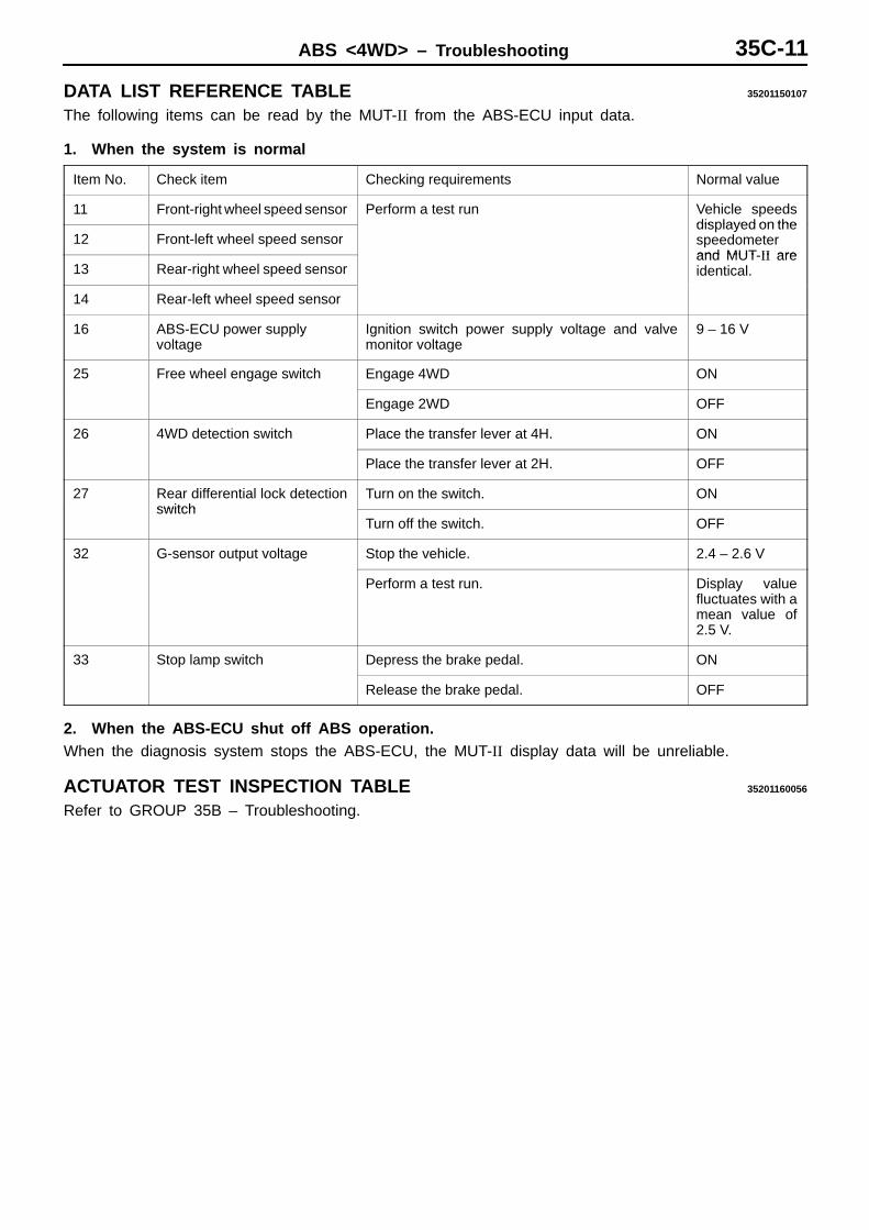
DATA LIST REFERENCE TABLE 35201150107
The following items can be read by the MUT-II from the ABS-ECU input data.
1. When the system is normal
Item No. Check item Checking requirements Normal value
11 Front-right wheel speed sensor Perform a test run Vehicle speedsdisplayed on the
12 Front-left wheel speed sensordis layed on thespeedometerand MUT II are
13 Rear-right wheel speed sensorand MUT-II areidentical.
14 Rear-left wheel speed sensor
16 ABS-ECU power supply voltage
Ignition switch power supply voltage and valvemonitor voltage
9 – 16 V
25 Free wheel engage switch Engage 4WD ON
Engage 2WD OFF
26 4WD detection switch Place the transfer lever at 4H. ON
Place the transfer lever at 2H. OFF
27 Rear differential lock detectionswitch
Turn on the switch. ONswitch
Turn off the switch. OFF
32 G-sensor output voltage Stop the vehicle. 2.4 – 2.6 V
Perform a test run. Display valuefluctuates with amean value of2.5 V.
33 Stop lamp switch Depress the brake pedal. ON
Release the brake pedal. OFF
2. When the ABS-ECU shut off ABS operation.When the diagnosis system stops the ABS-ECU, the MUT-II display data will be unreliable.
ACTUATOR TEST INSPECTION TABLE 35201160056
Refer to GROUP 35B – Troubleshooting.

ABS <4WD> – Troubleshooting35C-12
CHECK AT ABS-ECU 35201180137
TERMINAL VOLTAGE CHECK CHART1. Measure the voltages between terminals (15), (16), (25) and (42) (earth terminals) and each respective
terminal.
NOTEDo not measure terminal voltage for approx. 3 seconds after the ignition switch is turned on. TheABS-ECU performs the initial check for that period.
2. The terminal layouts are shown in the illustrations below.
ConnectorterminalNo.
Signal Checking requirements Normal condition
1 Output to front-left hydraulicunit solenoid valve (OUT side)
Ignition switch: ON(When solenoid valve is off approximately1 second after engine is started)
System voltage
2 Output to rear hydraulic unitsolenoid valve (OUT side)
1 second after engine is started)
3 Output to rear hydraulic unitsolenoid valve (IN side)
4 G-sensor signal Ignition switch: ON 2.4 – 2.6 V (Horizontalcondition)
13 ABS-ECU power supply Ignition switch: ON System voltage
Ignition switch: START 0 V
14 Output to front-left hydraulicunit solenoid valve (IN side)
Ignition switch: ON (When solenoid valveis off approximately 1 second after engineis started)
System voltage
17 G-sensor earth Always 0 V
26 Output to relay power supply Ignition switch: ON System voltage
31 Free wheel engage switch Ignitionswitch: ON
2WD System voltageswitch: ON
4WD 1 V or less
32 Memory power supply Always System voltage
34 Input from stop lamp switch Ignitionswitch: ON
Stop lamp switch ON System voltageswitch: ON
Stop lamp switch OFF 1 V or less
35 Input from 4WD detectionswitch
Ignitionswitch: ON
Transfer lever position: 2H System voltageswitch switch: ON
Transfer lever position: 4H 1 V or less
36 MUT-II Connect the MUT-II . Serial communicationwith MUT-II
Do not connect the MUT-II . 1 V or less

ABS <4WD> – Troubleshooting 35C-13
ConnectorterminalNo.
Signal Checking requirements Normal condition
37 Output to valve relay Ignitionswitch: ON
Approximately 1 secondafter engine is started.The relay is on.
2 V or less
The system runs down.The relay is off.
System voltage
38 Output to motor relay Ignition switch: ON(Approximately 1 second
Motor is on 2 V or less(A roximately 1 secondafter engine is started) Motor is off System voltage
39 Idle-up solenoid valve (+) Ignition switch: ON (When motor is onapproximately 1 second after engine isstarted)
System voltage
41 Output to front-right hydraulicunit solenoid valve (OUT side)
Ignition switch: ON (When solenoid valveis off approximately 1 second afterengine is started)
System voltage
43 Idle-up solenoid valve (–) Ignition switch: ON (When motor is onapproximately 1 second after engine isstarted)
2 V or less
45 Input from free wheel engageswitch
Ignitionswitch: ON
Engage 2WD System voltageswitch switch: ON
Engage 4WD 1 V or less
46*1 Ignition switch Ignition switch: ON System voltage
Ignition switch: START 0 V
46*2 Input from rear differentiallock detection switch
Ignitionswitch: ON
Rear differential lockswitch: ON
0 V
Rear differential lockswitch: OFF
System voltage
47 Input from diagnosisindication selection
Connect the MUT-II . 0 Vindication selection
Do not connect the MUT-II . Approx. 12 V
48 Input from valve relay monitor Ignition switch: ON System voltage
49 Motor monitor Ignition switch: ON(Approximately 1 second
Motor is on System voltage(A roximately 1 secondafter engine is started) Motor is off 0.5 V or less
50 Output to ABS warning lamp Ignitionswitch: ON
The lamp is switched off System voltageswitch: ON
The lamp illuminates 0 – 2 V
52 Output to front-right hydraulicunit solenoid valve (IN side)
Ignition switch: ON (When solenoid valveis off approximately 1 second afterengine is started)
System voltage
NOTE*1: Vehicles without rear differential lock*2: Vehicles with rear differential lock

ABS <4WD> – Troubleshooting35C-14
RESISTANCE AND CONTINUITY BETWEEN HARNESS-SIDE CONNECTOR TERMINALS1. Turn the ignition switch off and disconnect the ABS-ECU connectors before checking resistance and
continuity.2. Check them between the terminals indicated in the table below.3. The terminal layouts are shown in the illustrations below.
Connector terminal No. Signal Normal condition
1 – Body earth Front-left solenoid valve (OUT side) 2.2 Ω
2 – Body earth Rear solenoid valve (OUT side) 2.2 Ω
3 – Body earth Rear solenoid valve (IN side) 5.0 Ω
7 – 20 Front-left wheel speed sensor (+ wire)
1.2 – 1.4 kΩ
8 – 21 Rear-right wheel speed sensor (+ wire)
1.2 – 1.4 kΩ
9 – 22 Rear-left wheel speed sensor (+ wire) 1.2 – 1.4 kΩ
10 – 23 Front-right wheel speed sensor (+ wire)
1.2 – 1.4 kΩ
14 – Body earth Front-left solenoid valve (IN side) 5.0 Ω
15 – Body earth ABS-ECU earth Continuity
16 – Body earth
25 – Body earth
39 – 43 Idle-up solenoid valve 37 – 44 Ω
41 – Body earth Front-right solenoid valve (OUT side) 2.2 Ω
42 – Body earth ABS-ECU earth Continuity
48 – Body earth Input from valve relay monitor Continuity
49 – Body earth Motor monitor Continuity
52 – Body earth Front-right solenoid valve (IN side) 5.0 Ω

ABS <4WD> – Front Disc Brake 35C-15
FRONT DISC BRAKE 35200600023
REMOVAL AND INSTALLATION
Pre-removal Operation Brake Fluid Draining
Post-installation Operation Brake Fluid Supplying Brake Line Bleeding
(Refer to GROUP 35B – On-vehicle Service.)
90 Nm
90 Nm
15 Nm1
2
3
4
Removal steps1. Brake tube2. Front brake assembly (Refer to
GROUP 35B – Front Disc Brake.)3. Brake hose bracket4. Brake disc (Refer to GROUP 26 –
Front Hub Assembly.)

ABS <4WD> – Front Disc Brake35C-16
DISASSEMBLY AND REASSEMBLY 35200620029
74 Nm
6
CautionThe piston seal inside the seal andboot kit is coated with special grease,so do not wipe this grease off.
Brake fluid: DOT3 or DOT4
Brake caliper kit Pad kit Seal and boot kit
Grease
8 Nm
1
2
3
4
5
678
9
10
1112
13
14
8
9
14
2
13
59
87
6
1314
11
12
14
1213
9 7 5
35
Caliper assembly disassemblysteps
A 1. Lock pinA 2. Guide pin
3. Bushing4. Caliper support
(Pad, clip and shim)5. Pin boot6. Boot ring
A 7. Piston bootA 8. PistonB 9. Piston seal
10. Caliper body
Pad assembly disassembly stepsA 1. Lock pinA 2. Guide pin
3. Bushing4. Caliper support
(Pad, clip and shim)11. Pad and wear indicator assembly12. Pad assembly13. Outer shim14. Clip

ABS <4WD> – Front Disc Brake 35C-17
DISASSEMBLY SERVICE POINTSWhen disassembling the disc brakes, disassemble both sides(left and right) as a set.
APISTON BOOT/PISTON REMOVALPump in compressed air through the brake hose installationhole and remove the pistons and piston boot.
CautionWhen removing the pistons, be sure to use the handleof a plastic hammer and adjust the height of the twopistons while pumping air slowly in so that the pistonsprotrude evenly.Do not remove one piston completely before trying toremove the other piston because it will becomeimpossible to remove the second piston.
BPISTON SEAL REMOVAL(1) Remove piston seal with finger tip.
CautionDo not use a screwdriver or other tool to preventdamage to inner cylinder.
(2) Clean piston surface and inner cylinder withtrichloro-ethylene, alcohol or specified brake fluid.
Specified brake fluid: DOT3 or DOT 4
REASSEMBLY SERVICE POINTA LOCK PIN/GUIDE PIN INSTALLATIONInstall the lock pin and the guide pin to the caliper bodyas illustrated.
INSPECTION 35200630015
Check cylinder for wear, damage or rust. Check piston surface for wear, damage or rust. Check caliper body or sleeve for wear. Check pad for damage or adhesion of grease, check
backing metal for damage.
Piston seal
Guide pin
Lock pin

ABS <4WD> – Front Disc Brake35C-18
PAD WEAR CHECKMeasure thickness at the thinnest and worn area of the pad.Replace pad assembly if pad thickness is less than the limitvalue.
Standard value: 10 mm
Limit: 2.0 mm
Caution1. When the limit is exceeded, replace the pads at both
sides, and also the brake pads for the wheels onthe opposite side at the same time.
2. If there is a significant difference in the thicknessesof the pads on the left and right sides, check thesliding condition of the piston, lock pin and guidepin.

ABS <4WD> – Wheel Speed Sensor 35C-19
WHEEL SPEED SENSOR 35200830170
REMOVAL AND INSTALLATION
Post-installation Operation Wheel Speed Sensor Output Voltage Checking
(Refer to GROUP 35B – On-vehicle Service.)
1
2
1. Front speed sensor2. Front rotor
(Refer to GROUP 26 – Front Hub.)
NOTEThe rear wheel speed sensor is the same as 2WD.
INSPECTION 35200840135
Refer to GROUP 35B.

ABS <4WD> – G-Sensor35C-20
G-SENSOR 35201010078
REMOVAL AND INSTALLATION
CAUTION: SRSWhen removing and installing the G-sensorfrom/to vehicles equipped with SRS, do not let itbump against the SRS diagnostic unit or othercomponents.
Pre-removal and Post-installation Operation SRS diagnostic unit Removal and Installation
(Refer to GROUP 52B.)
1
2
3
Removal steps1. G-sensor assembly2. G-sensor bracket3. G-sensor
CautionDo not drop the G-sensor or subject it to shocks.
INSPECTION 35201020057
(1) Disconnect the G-sensor connector and connect thespecial tool between the terminals of the disconnectedconnector.
(2) Turn the ignition switch to ON and take a reading ofthe following output voltage.Between terminals (2) and (3).
Standard value: 2.4 – 2.6 V
(3) With the special tool still connected, secure the G-sensorso that the arrow mark on the sensor mounting surfacefaces straight down, and then take a reading of thefollowing output voltage between terminals (2) and (3).
Standard value: 3.4 – 3.6 V
(4) If the voltages is outside the standard value, after checkingto be sure that there is no abnormality in the power supplyand earth wires, replace the G-sensor.
MB991348