anvil csi 3 part masterformat specifications · pdf filew. manufacturers standardization...
TRANSCRIPT
Anvil CSI 3 Part MasterFormat Specifications
BASIC MECHANICAL METHODS AND MATERIALS SECTION 23 05 00
PART 1 GENERAL
1.1 SECTION INCLUDES
A. Piping, couplings, fittings and valves for piped building systems.
1.2 RELATED SECTIONS
A. Section 23 05 29 - Hangers and Supports for HVAC Piping and Equipment.
B. Section 21 11 00 - Facility Fire-Suppression Water-Service Piping.
C. Section 22 30 00 - Plumbing Equipment.
D. Section 23 50 00 - Central Heating Equipment.
E. Section 23 60 00 - Central Cooling Equipment.
1.3 REFERENCES
A. American Society of Mechanical Engineers (ASME) B31.1 - Power Piping (SI Edition).
B. American Society of Mechanical Engineers (ASME) B31.3 - Chemical Plant and Petroleum Refinery Piping.
C. American Society of Mechanical Engineers (ASME) B31.9 - Building Services Piping.
D. ASTM International (ASTM) A36 - Standard Specification for Carbon Structural Steel.
E. ASTM International (ASTM) A47 - Standard Specification for Ferritic Malleable Iron Castings.
F. ASTM International (ASTM) A48 - Standard Specification for Gray Iron Castings.
G. ASTM International (ASTM) A53 - Standard Specification for Pipe, Steel, Black and Hot-Dipped, Zinc-Coated, Welded and Seamless.
H. ASTM International (ASTM) A123 - Standard Specification for Zinc (Hot-Dip Galvanized) Coatings on Iron and Steel Products.
I. ASTM International (ASTM) A153 - Specification for Zinc Coating (Hot Dip) on Iron & Steel Hardware.
J. ASTM International (ASTM) A240 - Standard Specification for Chromium and Chromium-Nickel Stainless Steel Plate,
Sheet, and Strip for Pressure Vessels and for General Applications.
K. ASTM International (ASTM) A387 - Standard Specification for Pressure Vessel Plates, Alloy Steel, Chromium-Molybdenum.
L. ASTM International (ASTM) A515 - Standard Specification for Pressure Vessel Plates, Carbon Steel, for Intermediate-and
Higher-Temperature Service.
M. ASTM International (ASTM) A536 - Standard Specification for Ductile Iron Castings.
N. ASTM International (ASTM) A575 - Standard Specification for Steel Bars, Carbon, Merchant Quality, M-Grades.
O. ASTM International (ASTM) A668 - Standard Specification for Steel Forgings, Carbon and Alloy, for General Industrial Use.
P. ASTM International (ASTM) A1011 - Standard Specification for Steel, Sheet and Strip, Hot-Rolled, Carbon, Structural,
High-Strength Low-Alloy and High-Strength Low-Alloy with Improved Formability.
Q. ASTM International (ASTM) B633 - Standard Specification for Electrodeposited Coatings of Zinc on Iron and Steel.
R. Manufacturers Standardization Society of The Valve and Fittings Industry (MSS) SP-58 Pipe Hangers and Supports - Materials,
Design and Manufacture.
S. Manufacturers Standardization Society of The Valve and Fittings Industry (MSS) SP-69 Pipe Hangers and Supports - Selection
and Application.
T. Manufacturers Standardization Society of The Valve and Fittings Industry (MSS) SP-77 Guidelines for Pipe Support Contractual
Relationships.
U. Manufacturers Standardization Society of The Valve and Fittings Industry (MSS) SP-89 Pipe Hangers and Supports - Fabrication
and Installation Practices.
V. Manufacturers Standardization Society of The Valve and Fittings Industry (MSS) SP-90 Guidelines on Terminology for Pipe
Hangers and Supports.
W. Manufacturers Standardization Society of The Valve and Fittings Industry (MSS) SP-127 Bracing for Piping Systems Seismic-
Wind-Dynamic Design, Selection, Application.
1.4 SYSTEM DESCRIPTION
A. Grooved Mechanical Products: Couplings, fittings, valves and grooved components shall be used as the piping method.
1. Product: Gruvlok as manufactured by Anvil International.
B. System Design Requirements:
1. Grooved products shall meet National and Local Piping and/or Building Codes. Mechanical commercial and industrial
piping products shall have a minimum 300-psi (2.4 MPa) working pressure with 3 to 1 or greater safety working pressure
with the exception of plain-end end fittings, which shall have a minimum of 175-psi (1.2MPa) working pressure.
2. Fire Protection UL/ULC listed and FM approved products shall conform to NFPA working pressures.
3. Incorporate in construction pipe hangers and supports to manufacturer’s recommendations utilizing manufacturer’s
regular production components, parts and assemblies. Grooved piping installation shall meet ANSI B-31.1 - ANSI B-31.9
standards for horizontal and vertical pipe support design criteria.
1.5 SUBMITTALS
A. Submit under provisions of Section 01 30 00.
B. [Product Data]: Manufacturer’s data sheets on each product to be used, including:
1. Preparation instructions and recommendations.
2. Installation methods.
C. Certifications:
1. Product certificates signed by manufacturer certifying materials comply with specified performance characteristics and
criteria and physical requirements. Certificates shall be furnished only as required by specific codes, upon request.
D. Selection Samples: For each finish product specified, two complete sets of color chips representing manufacturer’s full
range of available colors and patterns.
E. Verification Samples: For each finish product specified, two samples, minimum size 6 inches square, representing
actual product, color, and patterns.
F. Closeout Submittals:
1. Warranty: Warranty documents.
2. Operation and Maintenance Data: Operation and maintenance data for installed products in accordance with Division 1
Closeout Submittals (Maintenance Data and Operation Data) Section. Include methods for maintaining installed
products, and precautions against cleaning materials and methods detrimental to finishes and performance.
1.6 QUALITY ASSURANCE
A. Manufacturer Qualifications:
1. Manufacturing facilities shall be registered to ISO 9001:2000 and assessed to ISO 9000:2000 standard. A copy of the
current certificate shall be available upon request.
B. Conduct pre-installation meeting to verify project requirements, coordinate with other trades, and establish condition and
completeness of substrate. Review manufacturer’s installation instructions and manufacturer’s warranty requirements.
1.7 DELIVERY, STORAGE, AND HANDLING
A. Store products in manufacturer’s unopened packaging until ready for installation.
B. Store and dispose of solvent-based materials, and materials used with solvent-based materials, in accordance with
requirements of local authorities having jurisdiction.
1.8 PROJECT CONDITIONS
A. Maintain environmental conditions (temperature, humidity, and ventilation) within limits recommended by manufacturer
for optimum results. Do not install products under environmental conditions outside manufacturer’s absolute limits.
1.9 WARRANTY
A. Manufacturer’s Warranty: Submit, for Owner’s acceptance, manufacturer’s standard warranty document executed by
authorized company official. Manufacturer’s warranty is in addition to, and not a limitation of, other rights. Owner may
have under Contract Documents.
PART 2 PRODUCTS
2.1 MANUFACTURERS
A. Acceptable Manufacturer: Anvil International, which is located at: 2 Holland Way; Exeter, NH 03833;
Tel: 603-418-2800; Email: [email protected]; Web: www.anvilintl.com
B. Substitutions: Not permitted.
C. Requests for substitutions will be considered in accordance with provisions of Section 01 60 00.
2.2 PIPING
A. Steel Piping: Black Steel and/or galvanized pipe conforming to ASTM A-53, Grade A or B. Grooving shall conform to

Gruvlok published grooving specifications.
B. Steel Piping: Black Steel and/or galvanized pipe conforming to ASTM A-135 or A-795. Grooving shall conform to Gruvlok
published grooving specifications.
C. Steel Piping: Black Steel and/or galvanized pipe conforming to ASTM A-53, Grade A or B. Standard schedule 40 pipe
shall be roll or cut grooved. Grooving shall conform to Gruvlok published grooving specifications.
D. Steel Piping: Black Steel and/or galvanized pipe conforming to ASTM A-53, Grade A or B. Schedule 10 pipe and below
shall be roll grooved. Grooving shall conform to Gruvlok published grooving specifications.
E. Copper Tubing: Copper tube to comply with ASTM B-88.
1. Types K, L, M, and DWV shall be used in conjunction with the Gruvlok Copper Tube sizes grooving specifications.
2.3 FITTINGS
A. Material:
1. Couplings and Grooved Flange Adapters shall conform to ASTM A-536 Ductile Grade 65-45-12
2. Coupling Track Head Bolts shall conform to ASTM A-183 Grade 2.
3. Hex nuts shall conform to ASTM A-563 Grade A. Bolts and nuts shall be zinc electroplated to ASTM B-633.
4. Fittings shall conform to Cast Ductile ASTM A-536.
5. Forged steel fittings shall conform to ASTM A-234 or A-105.
6. Segmental welded fittings shall conform to ASTM A-53.
7. Coatings shall be (Orange) rust inhibiting lead free coating.
8. Coating shall be hot dipped galvanized fittings shall conform to ASTM A-153.
9. Standard coupling gaskets for building services shall be Grade “EP” EPDM conforming to ASTM D-2000 with operating
temperature range from -40 degrees F to +250 degrees F (-40 degrees C to 121 degrees C). or “E” EPDM conforming to
ASTM D-2000 with operating temperature range from -40 degrees F to +230 degrees F (-40 degrees C to 110 degrees C).
Or “E” type A Pre-Lubed EPDM for Fire Protection conforming to ASTM D-2000 with operating temperatures range from
-40 degrees F to 150 degrees F (-40 degrees C to 66 degrees C).
B. Gasket Lubricant: Coupling gaskets except where noted shall be lubricated with approved lubricant.
1. Copper Systems: Gruvlok Xtreme Lubricant.
2. Environments below -20 degrees F (-28 degrees C), and above 150 degrees F (66 degrees C) and systems subject to
continuous cycle temperature changes: Gruvlok Xtreme Lubricant.
3. Systems Subject to Thermal Cycling: Gruvlok Xtreme Lubricant.
4. “E” type A Pre-lubed Fire Protection Gaskets: No Lube required. Gruvlok Xtreme Lubricant required for dry pipe
applications.
C. Grooved Couplings for Steel Pipe Systems and other Approved Piping:
1. Sizes 1 inch to 30 inches; Gruvlok Style 7401 Rigidlok couplings shall be used including style
7788 flange adapters fittings or 7012 Flange adaptor.
2. Gruvlok Style 7402 SlideLOK ready to install coupling sizes 2 inch to 8 inch shall be used for rigid connections.
3. Gruvlok Style 7001 (Flexible) couplings shall be used for vibration attenuation and noise suppression at equipment
locations.
4. Combination rigid, flexible, and outlet couplings shall be used for vibration, noise suppression and seismic tremor.
5. Mechanical Clamp Tees style 7045, 7046 shall be used for branch outlets, cross configuration can be made with style
7047, 7048, & 7049.
6. Standard coupling gaskets for building services shall be Grade “EP” EPDM conforming to ASTM D-2000 with operating
temperature range from -40 degrees F to +250 degrees F (-40 degrees C to 121 degrees C). or “E” EPDM conforming to
ASTM D-2000 with operating temperature range from -40 degrees F to +230 degrees F (-40 degrees C to 110 degrees C).
Or “E” type A Pre-Lubed EPDM for Fire Protection conforming to ASTM D-2000 with operating temperatures range from
-40 degrees F to 150 degrees F (-40 degrees C to 66 degrees C).
7. Use other gasket materials as recommended for petroleum service and other applications, contact and Anvil Represenative
for gasket compatibility questions.
8. Flexible or other style couplings designed for axial motion or other movements shall be supported in strict accordance
with industry standards.
D. Grooved Couplings for Copper Tube Systems: Coupling working pressure not to exceed 300 psig (2.0 MPa).
1. Gruvlok style 6400 Rigidlite and style 6084 coupling flange adapters fittings.
2. Grade “EP” EPDM Flush Gap Gasket.
3. Gruvlok Xtreme Lubricant.
E. Grooved Flange Adapters:
1. Style 7788 Flange adaptor fittings shall be used to transition from grooved to flange connection.
a. Sizes 2 inches through 12 inches are rated at 300 psig (2.0 MPa).
b. Conforms to ANSI class 125 or 150.
1. Style 7012 & 7013 shall be used when space is at a premium .
a. Figures 7012 and 7013 flange adapters require sealing rings when used with certain flanged products.
b. Figure 7012: Conforms to ANSI class 125 or 150.
c. Sizes 2 inches through 20 inches are rated at 300 psig (2.0 MPa).
d. Size 24 inches is rated at 250 psig (1.72 MPa).
4. Figure 7013: 2 inches through 12 inches available for ANSI class 250 or 300 lb bolt pattern and
is rated at 750 psig (5 MPa).
F. Grooved Fittings for Steel Piping Systems - Shall be Gruvlok cast ductile, malleable, forged steel, and/or segmental welded
steel fittings.
1. Sizes 1 inches to 30 inches diameter:
a. Cast ductile conforms to ASTM A-536 or ASTM A-47.
b. Forged steel conforms to ASTM A-234.
c. Segmental welded conforms to ASTM A-53.
2. Fittings shall be coated with an rust inhibiting lead free coating.
3. Zinc electroplated fittings conform to ASTM B-633.
4. Hot Dip Galvanized fittings conform to ASTM A-153.
5. Standard Fittings shall be schedule 40 or standard wall. Other fittings are schedule 80 or light wall as dsigned.
G. Grooved Copper Fittings: Gruvlok Wrot Copper fittings per ASTM B-75 and ANSI B-16.22, alloy C12200.
1. Wrought Copper fittings size 2 inches to 8 type K, L, M, or DWV. Copper fittings shall be 99.9 percent lead free.
2. Couplings and Wrought Copper Fittings shall be NSF-61, UPC Plumbing Code, & low lead approved.
H. DI-LOK Gruvlok CTS Groove to IPS Groove Dielectric Fitting.
1. Carbon steel conforming to ASTM A106, Nylon coated
2. Operating Temperature -40 degrees F to +230 degrees F (-40 degrees C to 100 degrees C).
3. Size range 2 inch to 6 inch.
4. NSF-61, low lead approved.
I. Di-Electric Insulated Pipe Connections: Di-LOK Figure 7088 or 7089 grooved by grooved or grooved by thread insulating nipples.
1. Shall inhibit the formation of a galvanic cell between dissimilar metals.
2. Housing: Steel tube to comply with ASTM A513; zinc plated.
3. Liner: Polypropylene rated at 300 psig (2 MPa).
4. Operating Temperature -40 degrees F to +230 degrees F (-40 degrees C to 100 degrees C).
5. Size range is 1 inch to 6 inches diameter.
J. Branch Outlets: Shall be Gruvlok Clamp-T Styles 7045 and 7046, and Clamp-T Cross Figure 7047, 7048 and 7049 with
grooved or threaded outlets.
1. Designated as a bolted-on positive pipe engagement branch outlet. Working pressure on schedule 40 pipe rated to 500 psi
(3.5 KPa).
2. Run Sizes 2 inches to 8 inches.
3. Branch outlets from 1/2 inch to 3 inches diameter.
K. Outlet Couplings: Shall be Gruvlok Figure 7042 with grooved or threaded outlets. Working pressure shall be 500-psig minimum.
1. Run sizes 1-1/2 inches to 6 inches.
2. Branch outlets from 1/2 inch to 2 inches diameter.
L. Plain End Couplings and Fittings: Gruvlok Roughneck coupling Style 7005 and plain-end fittings to match.
1. Size range is 2 inches to 16 inches diameter.
2. Materials conform to ASTM A-536.
3. Intended for working pressures 300 to 750 psig (2.0 KPa to 5.2 KPa) with bolts fully torque to factory recommend torque
requirements on plain-end or beveled standard wall steel pipe and Gruvlok Plain-End fittings.
M. Plain End “Sock-it” Method: Gruvlok Sock-it fitting series 7100 through 7107.
1. Size range is 1 inch to 2-1/2 inches diameter.
2. Material conforms to ASTM A-126 Class A Cast Iron.
3. Working pressures from 175 - 300 psi (1.2 KPa to 2.0 KPa) UL/ULC listed and FM approved.
N. Gaskets for Industrial and Other Piping Systems: Systems with different media products shall be provided with industrial
grade gaskets as scheduled. Contact and Anvil Representative Gruvlok for application questions.
O. Track Head Bolts and Hex Nuts: Couplings shall be furnished with heat-treated; oval neck track head bolts conforming to
ASTM A-183 Grade 2. Bolts shall meet minimum tensile strength of 110,000 psi (758 KPa). Hex nuts shall be carbon
steel conforming to ASTM A-563 Grade A. Bolts and nuts shall be zinc electroplated per ASTM B-633.
2.4 GROOVED CONNECTION FLOW CONTROL VALVES
A. Gruvlok Tri-Service Valves - Model FTV-S.
B. Gruvlok Tri-Service Valves - Model FTV-A.
1. Size: As indicated on drawings.
2. Body and Yoke: Ductile iron; comply with ASTM A395 or ASTM A536.
3. Disc: Cast iron, comply with ASTM A126.
4. Stem: Bronze, comply with ASTM B21.
5. Seat-Guide: Bronze, comply with ATM B584.
6. Disc Guide: Cast iron, comply with ASTM A126.
7. Seat: Bronze.
8. Flanged Gland: Cast iron, comply with ASTM A126.
9. Packing: Graphited, non-asbestos packing.
10. Spring: 302 stainless steel.
11. Stem Guide: Ductile iron; comply with ASTM A395 or ASTM A536.
C. Gruvlok Balancing Valves - Model GBV-S (Soldered).
D. Gruvlok Balancing Valves - Model GBV-T (Threaded).
1. Size: As indicated on drawings.
2. Material: Cast bronze.
3. Type and Description: Y-style globe valve with 4 full-turn adjustment, pressure differential ports on both sides of the
valve, with positive shutoff and micrometer type handwheel adjustment. Provide tamperproof memory stop.
E. Gruvlok Balancing Valves - Model GBV-G (Grooved-End Straight).
F. Gruvlok Balancing Valves - Model GBV-A (Grooved-End Angle).
1. Size: As indicated on drawings.
2. Body: Ductile iron, comply with ASTM A536.
3. Disc: Bronze, comply with ASTM B584.
4. Seat: Ultra-high strength engineered resin.
5. Trim: Brass C-37700.
6. O-ring: Nitrile.
G. Gruvlok Butterfly Valves - Series 7700:
1. Size: As indicated on drawings.
2. Body: Ductile iron; comply with ASTM A536, Grade 65-42-12.
3. Body Coating: Nylon.
4. Disc: Ductile iron; comply with ASTM A536, Grade 65-42-12.
5. Grade: Grade E - EPDM.
6. Grade: Grade T - Nitrile.
7. Upper and Lower Shaft: Type 416 stainless steel.
2.5 EQUIPMENT ANCHOR BOLTS AND TEMPLATES
A. Provide templates to ensure accurate location of anchor bolts.
PART 3 EXECUTION
3.1 EXAMINATION
A. Do not begin installation until substrates have been properly prepared.
B. If substrate preparation is the responsibility of another installer, notify Architect of unsatisfactory preparation before proceeding.
3.2 PREPARATION
A. Clean surfaces thoroughly prior to installation.
B. Prepare surfaces using the methods recommended by the manufacturer for achieving the best result for the substrate under
the project conditions.
3.3 INSTALLATION
A. General: Grooved piping installation shall meet ANSI B-31.1 - ANSI B-31.9 Codes for Pressure Piping.
B. Install in accordance with manufacturer’s instructions.
C. Pipe ends shall be clean and free from indentations, burrs, rust or damage.
D. Field grooving or pipe cutting of galvanized pipe may require repair of possible damaged galvanized pipe ends. Two coats
of spray-on “liquid-galvanize” are recommended.
E. Install rigid couplings with tongue-and-groove housing for precise coupling alignment and engagement. Install tines in the
housing key section to provide a rigid-like pipe connection.
F. Companion or mating flanges shall have a flat hard surface and shall be free from gouges, undulations or deformities. Use
flange gasket sealing rings if mating surfaces are not uniform.
G. Plain-end coupling and fitting installation shall comply with specific torque and installation requirements. Consult current
manufacturer’s product installation data.
H. Gasket lubricant shall be used to assure proper coupling gasket seating, and conformance with gasket service usage.
3.4 VALVE INSTALLATION
A. Tri-Service Valves - Models FTV-S, FTV-A:
1. Mount valve to a spool piece on the discharge side of the pump. Spool piece required is based on a minimum recommended
space of 12 inches for pump sizes 2 inches by 2 inches to 6 inches by 6 inches and 24 inches for pump sizes 8
inches by 8 inches to 12 inches by 12 inches.
2. Do not mount valve directly to pump to avoid causing undesirable noise in the system.
3. Leave sufficient clearance around valve for valve removal or repair.
4. Install valve in the direction of flow arrows on valve body.
5. Mount valve to flanged equipment using Gruvlok Flange Adapter or industry standard grooved coupling, suitable for
system pressure and temperatures encountered.
6. Valve body has been designed to handle the weight of the pump on vertical in-line installations. The valve body is not
designed to support the piping weight. Support piping by hangers. Provide pipe supports under valve and strainer bodies.
B. Globe Valves - Model GBV-S (Soldered), GBV-T (Threaded), Balancing Valves - Model GBV-G (Grooved-End Straight),
GBV-A (Grooved-End Angle):
1. To ensure accuracy of measurement of GBV-S, GBV-T, GBV-G and GBV-A valves, locate valves at least 5 pipe diameters
downstream from any fitting and at least 10 pipe diameters downstream from a pump.
2. Install no fittings within 2 pipe diameters downstream of valve.
3. Install valves with flow in the direction of the arrow on the valve body.
4. Provide easy access to probe metering ports (PMPs), drain ports and handwheel.
5. For solder applications, solder valve body in line using 95/5 solder.
6. Install valve-bonnet assembly into body, making sure non-asbestos gasket is in place.
7. Install valves in horizontal or vertical piping as indicated.
8. Do not install metering ports below the pipe (pointing down), as this will allow system sediment to accumulate in the ports.
9. Metering ports and body/drain plugs may be interchanged for improved accessibility.
END OF SECTION
HANGERS AND SUPPORTS SECTION 23 05 29
PART 4 GENERAL
4.1 SECTION INCLUDES
A. Hangers and supports for mechanical piping, ducting and equipment.
4.2 RELATED SECTIONS
A. Division 3 Section: Cast-in-Place Concrete.
B. Division 5 Section: Structural Steel.
C. Division 5 Section: Metal Fabrications.
4.3 REFERENCES
A. American Society of Mechanical Engineers (ASME):
1. B31.1 - Power Piping (SI Edition).
2. B31.3 - Chemical Plant and Petroleum Refinery Piping.
3. B31.9 - Building Services Piping.
B. ASTM International (ASTM):
1. A36 - Standard Specification for Carbon Structural Steel.
2. A47 - Standard Specification for Ferritic Malleable Iron Castings.
3. A48 - Standard Specification for Gray Iron Castings.
4. A53 - Standard Specification for Pipe, Steel, Black and Hot-Dipped, Zinc-Coated, Welded and Seamless.
5. A123 - Standard Specification for Zinc (Hot-Dip Galvanized) Coatings on Iron and Steel Products.
6. A240 - Standard Specification for Chromium and Chromium-Nickel Stainless Steel Plate, Sheet, and Strip for Pressure
Vessels and for General Applications.
7. A387 - Standard Specification for Pressure Vessel Plates, Alloy Steel, Chromium-Molybdenum.
8. A515 - Standard Specification for Pressure Vessel Plates, Carbon Steel, for Intermediate-and Higher-Temperature Service.
9. A536 - Standard Specification for Ductile Iron Castings.
10. A575 - Standard Specification for Steel Bars, Carbon, Merchant Quality, M-Grades.
11. A668 - Standard Specification for Steel Forgings, Carbon and Alloy, for General Industrial Use.
12. A1011 - Standard Specification for Steel, Sheet and Strip, Hot-Rolled, Carbon, Structural, High-Strength Low-Alloy and
High-Strength Low-Alloy with Improved Formability.
13. B633 - Standard Specification for Electrodeposited Coatings of Zinc on Iron and Steel.
C. Manufacturers Standardization Society of The Valve and Fittings Industry (MSS) Standard Practices:
1. SP-58 Pipe Hangers and Supports - Materials, Design and Manufacture.
2. SP-69 Pipe Hangers and Supports - Selection and Application.
3. SP-77 Guidelines for Pipe Support Contractual Relationships.
4. SP-90 Guidelines on Terminology for Pipe Hangers and Supports.
5. SP-127 Bracing for Piping Systems Seismic-Wind-Dynamic Design, Selection, Application.
4.4 SYSTEM DESCRIPTION
A. Contractor General Requirements:
1. Incorporate in construction pipe hangers and supports to manufacturer’s recommendations utilizing manufacturer’s
regular production components, parts and assemblies.
2. Comply with maximum load ratings with consideration for allowable stresses prescribed by ASME B31.1 or MSS SP-58.
3. Provide supports, guides and anchors that do not transmit unacceptable heat and vibration to building structure.
4. The selection of pipe hangers and supports shall be based upon the overall design concept of the piping systems and
any special requirements, which may be called for in the specifications. The support systems shall provide for, and
control, the free or intended movement of the piping including its movement in relation to that of connected equipment.
(Extracted from ANSI/MSS-SP69, 2003, Page 1, Section 4.2, with permission of the publisher, the Manufacturers
Standardization Society.)
5. Provide for vertical adjustments after installation of supported material and during commissioning, where feasible, to
ensure pipe is at design elevation and slope.
B. Selection of Hangers and Supports for Pipe Movement:
1. Select hangers and supports to perform under all conditions of operation, allowing free expansion and contraction,
and to prevent excessive stresses being introduced into piping system and connected equipment.
2. Angularity of rod hanger resulting from horizontal movement of the piping system from cold to hot positions shall not
to exceed 4 degrees from vertical.
3. Where horizontal pipe movement is greater than 1/2 inch offset pipe hanger and support so that rod
hanger is vertical in hot position.
4. Where significant vertical movement of the pipe occurs at the hanger location, a resilient support must be used. Selection
of resilient supports shall be based on permissible load variation and effects on adjacent equipment. Support selection
for typical load variations are shown in Table 2 of MSS-SP-69. Load and movement calculations shall be made for the
proper selection of spring hangers. Vertical movement and load transfer from riser expansion to horizontal runs shall
be given consideration when applying spring hangers. Spring Cushion Hangers may be used where vertical movement
does not exceed 1/4 inch, and where formal load and movement calculations are not required. Variable spring
Hangers shall be used for all other resilient support requirements. Constant Support Hangers shall be used on piping
systems where the deviation in supporting force must be limited to 6 percent and which cannot be accommodated by
a Variable Spring Hanger. (Extracted from ANSI/MSS-SP69, 2003, Page 7, Section 7.4 and 7.4.1 to 7.4.3, inclusive,
with permission of the publisher, the Manufacturers Standardization Society.)
C. Hanger Spacing: (Extracted from ANSI/MSS-SP69, 2003, Page 8, Table 3, with permission of the publisher, the Manufacturers
Standardization Society.)
D. Pipe Attachments for Insulated Lines:
1. The connections to pipe attachments shall be outside the insulation so that movement of the line shall not cause damage
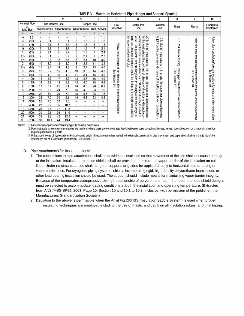
D. Pipe Attachments for Insulated Lines:
1. The connections to pipe attachments shall be outside the insulation so that movement of the line shall not cause damage
to the insulation. Insulation protection shields shall be provided to protect the vapor barrier of the insulation on cold
lines. Under no circumstances shall hangers, supports or guides be applied directly to horizontal pipe or tubing on
vapor barrier lines. For cryogenic piping systems, shields incorporating rigid, high-density polyurethane foam inserts or
other load bearing insulation should be used. The support should include means for maintaining vapor barrier integrity.
Because of the temperature/compressive strength relationship of polyurethane foam, the recommended shield designs
must be selected to accommodate loading conditions at both the installation and operating temperature. (Extracted
from ANSI/MSS-SP69, 2003, Page 10, Section 10 and 10.1 to 10.3, inclusive, with permission of the publisher, the
Manufacturers Standardization Society.)
2. Deviation to the above is permissible when the Anvil Fig 260 ISS (Insulation Saddle System) is used when proper
insulating techniques are employed including the use of mastic and caulk on all insulation edges, and final taping.
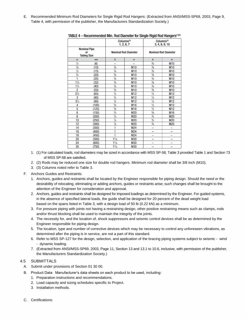
E. Recommended Minimum Rod Diameters for Single Rigid Rod Hangers: (Extracted from ANSI/MSS-SP69, 2003, Page 9,
Table 4, with permission of the publisher, the Manufacturers Standardization Society.)
1. (1) For calculated loads, rod diameters may be sized in accordance with MSS SP-58, Table 3 provided Table 1 and Section 73
of MSS SP-58 are satisfied.
2. (2) Rods may be reduced one size for double rod hangers. Minimum rod diameter shall be 3/8 inch (M10).
3. (3) Columns noted refer to Table 3.
F. Anchors Guides and Restraints:
1. Anchors, guides and restraints shall be located by the Engineer responsible for piping design. Should the need or the
desirability of relocating, eliminating or adding anchors, guides or restraints arise; such changes shall be brought to the
attention of the Engineer for consideration and approval.
2. Anchors, guides and restraints shall be designed for imposed loadings as determined by the Engineer. For guided systems,
in the absence of specified lateral loads, the guide shall be designed for 20 percent of the dead weight load
based on the spans listed in Table 3, with a design load of 50 lb (0.22 kN) as a minimum.
3. For pressure piping with joints not having a restraining design, other positive restraining means such as clamps, rods
and/or thrust blocking shall be used to maintain the integrity of the joints.
4. The necessity for, and the location of, shock suppressors and seismic control devices shall be as determined by the
Engineer responsible for piping design.
5. The location, type and number of corrective devices which may be necessary to control any unforeseen vibrations, as
determined after the piping is in service, are not a part of this standard.
6. Refer to MSS SP-127 for the design, selection, and application of the bracing piping systems subject to seismic - wind
- dynamic loading.
7. (Extracted from ANSI/MSS-SP69, 2003, Page 11, Section 13 and 13.1 to 10.6, inclusive, with permission of the publisher,
the Manufacturers Standardization Society.)
4.5 SUBMITTALS
A. Submit under provisions of Section 01 30 00.
B. Product Data: Manufacturer’s data sheets on each product to be used, including:
1. Preparation instructions and recommendations.
2. Load capacity and sizing schedules specific to Project.
3. Installation methods.
C. Certifications:
1. Product certificates signed by manufacturer certifying materials comply with specified performance characteristics and
criteria and physical requirements. Certificates shall be furnished only as required by specific codes, upon request.
D. Shop Drawings:
1. Bases, hangers and supports.
2. Connections to equipment and structure.
3. Structural assemblies.
E. Selection Samples: For each finish product specified, two complete sets of color chips representing manufacturer’s full
range of available colors and patterns.
F. Verification Samples: For each finish product specified, two samples, minimum size 6 inches square, representing
actual product, color, and patterns.
G. Closeout Submittals:
1. Warranty: Warranty documents.
2. Operation and Maintenance Data: Operation and maintenance data for installed products in accordance with Division 1
Closeout Submittals (Maintenance Data and Operation Data) Section. Include methods for maintaining installed products,
and precautions against cleaning materials and methods detrimental to finishes and performance.
4.6 QUALITY ASSURANCE
A. Manufacturer Qualifications:
1. Manufacturing facilities shall be registered to ISO 9001.2000 and assessed to ISO 9000.2000 standard. A copy of the
current certificate shall be available upon request.
B. Installer Qualifications:
1. Utilize an installer experienced in performing work of this section who is experienced in installation of work similar
to that required for this project and per the minimum requirements of MSS SP-89.
C. Conduct pre-installation meeting to verify project requirements, coordinate with other trades, and establish condition and
completeness of substrate. Review manufacturer’s installation instructions and manufacturer’s warranty requirements.
4.7 DELIVERY, STORAGE, AND HANDLING
A. Store products in manufacturer’s unopened packaging until ready for installation.
B. Store and dispose of solvent-based materials, and materials used with solvent-based materials, in accordance with
requirements of local authorities having jurisdiction.
4.8 PROJECT CONDITIONS
A. Maintain environmental conditions (temperature, humidity, and ventilation) within limits recommended by manufacturer
for optimum results. Do not install products under environmental conditions outside manufacturer’s absolute limits.
4.9 WARRANTY
A. Manufacturer’s Warranty: Submit, for Owner’s acceptance, manufacturer’s standard warranty document executed by
authorized company official. Manufacturer’s warranty is in addition to, and not a limitation of, other rights, Owner may
have under Contract Documents.
PART 5 PRODUCTS
5.1 MANUFACTURERS
A. Acceptable Manufacturer: Anvil International, which is located at: 2 Holland Way; Exeter, NH 03833;
Tel: 603-418-2800; Email: [email protected]; Web: www.anvilintl.com
B. Substitutions: Not permitted.
C. Requests for substitutions will be considered in accordance with provisions of Section 01 60 00.
5.2 MANUFACTURED UNITS - APPLICATION REQUIREMENTS
A. Fabricate hangers, supports and sway braces to comply with building codes.
B. Do not use installed hangers for rigging or erection purposes.
C. Materials available by product type. Provide materials to comply with location and application requirements unless noted
otherwise on drawings and schedules.
1. Pipe rings - Malleable iron, carbon steel, stainless steel.
2. Clevis - Carbon steel, stainless steel.
3. Steel pipe clamps - Carbon steel, alloy, stainless steel.
4. Socket clamps - Carbon steel.
5. Beam clamps - Malleable/ductile iron, hardened steel, carbon steel, forged steel.
6. Structural attachments - Carbon steel, malleable iron.
7. Ceiling plates/ceiling flanges - Plastic, cast iron, malleable iron.
8. Concrete inserts and attachments – Malleable iron, carbon steel; stainless steel body, fiberglass bars, polypropylene
disc (iron cross design).
9. Rod attachments - Carbon steel, malleable iron, forged steel.
10. Pipe supports - Carbon steel, cast iron.
11. Pipe shields and saddles - Carbon steel, alloy steel, stainless steel.
12. Pipe rolls - Cast iron, carbon steel.
13. Guides - Carbon steel; slides, carbon steel with PTFE slide plates.
14. Engineered hangers - Carbon steel, stainless steel, chrome molybdenum steel.
D. Finishes: Provide finishes to comply with location and application requirements unless noted otherwise on drawings and
schedules.
1. Electro-plating galvanizing process per ASTM B633.
2. Hot Dipped galvanizing process per ASTM A153.
3. Epoxy paint.
4. Zinc-rich paint.
5. Standard primer shall meet Fed Spec TT-P-636.
E. Application Requirements: Use components for intended service conditions only. Comply with service requirements
below unless noted otherwise on drawings and schedules.
1. Steel hangers in contact with copper piping shall be copper plated, copper painted or epoxy coated.
2. Exterior utility and mechanical yard areas shall use piping that is hot dip galvanized.
3. Interior piping to be black iron.
4. Hydronics and plumbing piping hangers shall be manufactured from carbon steel, cast malleable iron or cast iron.
5. Steam piping hangers shall be manufactured from Chrome Molybdenum steel.
6. Submerged piping hangers shall be manufactured from 316 stainless steel.
5.3 MANUFACTURED UNITS - MSS-SP-69 TYPES NOTED FOR PRODUCTS THAT ARE IN COMPLIANCE
A. Copper Tubing Hangers: Fig. Numbers.
1. CT65 Light Weight Adjustable Clevis.
2. CT69 Adjustable Swivel Ring, MSS-SP-69 (Type 10).
3. CT109 Split Tubing Ring (Ring Only), MSS-SP-69 (Type 11).
4. CT121 Copper Tubing Riser Clamp, MSS-SP-69 (Type 8).
5. CT121C Copper Tubing Riser Clamp.
6. CT128R Rod Threaded Ceiling Flange.
7. CT138R Extension Split Tubing Clamp (Rod Threaded), MSS-SP-69 (Type 12).
8. CT255 Copper Tubing Alignment Guide.
9. 67F Copper Tube Felt Lined Hanger.
10. 69F Adjustable Swivel Ring Felt Lined.
B. CPVC Hangers
1. 185 One Hole Pipe Strap
2. 186 Two Hole Pipe Strap
3. 187 Two Hole 90 Degree Side Mount Strap
4. 188 Two Hole Stand Off Strap
B. Pipe Rings: Fig. Numbers.
1. 67 Pipe or Conduit Hanger, MSS-SP-69 (Type 5).
2. 69 Adjustable Swivel Ring, Tapped per NFPA Standards, MSS-SP-69 (Type 10).
3. 104 Adjustable Swivel Ring, Split Ring Type, MSS-SP-69 (Type 6).
4. 108 Split Pipe Ring, MSS-SP-69 (Type 11).
5. 138R Extension Split Pipe Clamp (Rod Threaded), MSS-SP-69 (Type 12).
C. Clevis: Fig. Numbers.
1. 65 Light Duty Adjustable Clevis.
2. 67 Pipe or Conduit Hanger, MSS-SP-69 (Type 5).
3. 260 ISS (Insulation Saddle System) for support of insulated pipe operating between –40 degrees F to 200 degrees F.
See section 2.3.P.11 for additional information.
4. 260 Adjustable Clevis Hanger, MSS-SP-69 (Type 1).
5. 300 Adjustable Clevis for Insulated Lines, MSS-SP-69 (Type 1).
6. 590 Adjustable Clevis for Ductile or Cast Iron Pipe, MSS-SP-69 (Type 1).
D. Steel Pipe Clamps: Fig. Numbers.
1. 40 Riser Clamp - Standard, MSS-SP-69 (Type 42).
2. 100 Extended Pipe Clamp.
3. 103 Offset Pipe Clamp.
4. 212 Medium Pipe Clamp, MSS-SP-69 (Type 4).
5. 212FP Earthquake Bracing Clamp, MSS-SP-69 (Type 4).
6. 216 Heavy Pipe Clamp, MSS-SP-69 (Type 4).
7. 224 Alloy Steel Pipe Clamp, MSS-SP-69 (Type 2).
8. 246 Heavy Duty Alloy Steel Pipe Clamp, MSS-SP-69 (Type 2).
9. 261 Extension Pipe or Riser Clamp, MSS-SP-69 (Type 8).
10. 295 Double Bolt Pipe Clamp, MSS-SP-69 (Type 3).
11. 295A Alloy Double Bolt Pipe Clamp, MSS-SP-69 (Type 3).
12. 295H Heavy Duty Double Bolt Pipe Clamp, MSS-SP-69 (Type 3).
E. Steel Riser Clamps: Fig. Numbers.
1. 40 Riser Clamp - Standard, MSS-SP-69 (Type 42).
2. 261 Extension Pipe or Riser Clamp, MSS-SP-69 (Type 8).
F. Socket Clamps (AWWA/Ductile/Cast Iron Pipe Sizes Only): Fig. Numbers.
1. 594 Socket Clamp Washer.
2. 595 Socket Clamp for Ductile Iron or Cast Iron Pipe, MSS-SP-69 (Type 8).
3. 599 Socket Clamp Washer.
4. 600 Socket Clamp for Ductile Iron or Cast Iron Pipe, MSS-SP-69 (Type 8).
G. Beam Clamps: Fig. Numbers.
1. 14 Adjustable Side Beam Clamp, MSS-SP-69 (Type 27).
2. 86 C-Clamp with Set Screw & Lock Nut, MSS-SP-69 (Type 23).
3. 87 C-Clamp with Set Screw & Fig. 89 Retaining Clip, MSS-SP-69 (Type 23).
4. 88 C-Clamp with Set Screw Only, MSS-SP-69 (Type 23).
5. 89 Retaining Clip.
6. 89X Retaining Clip.
7. 92 Universal C-type Clamp (Standard Throat), MSS-SP-69 (Type 19 and 23).
8. 93 Universal C-type Clamp (Wide Throat), MSS-SP-69 (Type 19 and 23).
9. 94 Wide Throat Top Beam C-Clamp, MSS-SP-69 (Type 19).
10. 95 C-Clamp with Locknut, MSS-SP-69 (Type 23).
11. 133 Standard Duty Beam Clamp, MSS-SP-69 (Type 21).
12. 134 Heavy Duty Beam Clamp, MSS-SP-69 (Type 21).
13. 217 Adjustable Side Beam Clamp, MSS-SP-69 (Type 25).
14. 218 Malleable Beam Clamp without Extension Piece, MSS-SP-69 (Type 30).
15. 227 Top Beam Clamp, MSS-SP-69 (Type 25).
16. 228 Universal Forged Steel (UFS) Beam Clamp, MSS-SP-69 (Type 28 and 29).
17. 292 Beam Clamp Right Hand Thread with Weld less Eye Nut, MSS-SP-69 (Type 28 and 29).
18. 292L Beam Clamp Left Hand Thread with Weld less Eye Nut, MSS-SP-69 (Type 28 and 29).
H. Structural Attachments: Fig. Numbers.
1. 54 Two Hole Welding Beam Lug.
2. 55 Structural Welding Lug (Short), MSS-SP-69 (Type 57).
3. 55L Structural Welding Lug (Long), MSS-SP-69 (Type 57).
4. 60 Steel Washer Plate.
5. 66 Welded Beam Attachment, MSS-SP-69 (Type 22).
6. 112 Brace Fitting Complete.
7. 113 Brace Fitting (Pipe End Only).
I. Ceiling Plates and Ceiling Flanges: Fig. Numbers.
1. 127 Plastic Ceiling Plate.
2. 128 Pipe Threaded, Ceiling Flange.
3. 128R Rod Threaded, Ceiling Flange.
4. 153 Pipe Hanger Flange.
5. 395 Cast Iron Ceiling Plate.
J. Brackets: Fig. Numbers.
1. 194 Light Welded Steel Bracket, MSS-SP-69 (Type 31).
2. 195 Medium Welded Steel Bracket, MSS-SP-69 (Type 32).
3. 199 Heavy Welded Steel Bracket, MSS-SP-69 (Type 33).
4. 202 Iron Side Beam Bracket, MSS-SP-69 (Type 34).
5. 206 Steel Side Beam Bracket, MSS-SP-69 (Type 34).
6. 207 Threaded Steel Side Beam Bracket, MSS-SP-69 (Type 34).
7. 189 Straight Eye Socket UL, ULC and FM.
8. 190 Off-Set Eye Socket UL, ULC, FM
K. Concrete Inserts and Attachments: Fig. Numbers.
1. 47 Concrete Single Lug Plate.
2. 49 Concrete Clevis Plate.
3. 52 Concrete Rod Attachment Plate.
4. 152 Screw Concrete Insert.
5. 281 Wedge Type Concrete Insert, MSS-SP-69 (Type 18).
6. 282 Universal Concrete Insert, MSS-SP-69 (Type 18).
7. 285 Light Weight Concrete Insert, MSS-SP-69 (Type 19).
8. 286 Iron Cross Design, MSS-SP-69 (Type 18).
L. Hanger Rod and Rod Attachments: Fig. Numbers.
1. 110R Socket, Rod Threaded, MSS-SP-69 (Type 16).
2. 114 Turnbuckle Adjuster, MSS-SP-69 (Type 15).
3. 135 Straight Rod Coupling (With Sight-Hole).
4. 135E Straight Rod Coupling (Less Sight-Hole).
5. 135R Straight Rod Coupling (Reducing).
6. 136 Straight Rod Coupling, MSS-SP-69 (Type 40).
7. 136R Straight Rod Coupling (Reducing).
8. 140 Machine Threaded Rod. Threaded both ends with right-hand threads.
9. 142 Machine Threaded Coach Screw Rod. Plain finish.
10. 146 Continuous Machine Threaded Rods.
11. 148 Machine Threaded Rod with Eye End.
12. 157 Extension piece.
13. 230 Turnbuckle, MSS-SP-69 (Type 13).
14. 233 Turnbuckle, MSS-SP-69 (Type 13).
15. 248 Machine Threaded Rod with Eye End. Right-hand threads with un-welded eye.
16. 248L Machine Threaded Rod with Eye End. Left-hand threads with un-welded eye.
17. 248X Machine Threaded Rod with Linked Eye Ends. Un-welded eye.
18. 253 Machine Threaded Rod. Threaded both ends with right-hand and left-hand threads.
19. 278 Machine Threaded Rod with Eye End. Right-hand threads with welded eye.
20. 278L Machine Threaded Rod with Eye End. Left-hand threads with welded eye.
21. 278X Machine Threaded Rod with Linked Eye Ends. Welded eye.
22. 290 Thread Weld less Eye Nut (Right Hand Threads), MSS-SP-69 (Type 17).
23. 290L Thread Weld less Eye Nut (Left Hand Threads), MSS-SP-69 (Type 17).
24. 299 Forged Steel Clevis, MSS-SP-69 (Type 14).
M. U-Bolts and Straps: Fig. Numbers.
1. 120 Light Weight U-Bolt.
2. 126 One-Hole Clamp.
3. 137 Standard U-Bolts, MSS-SP-69 (Type 24).
4. 137C Plastic Coated U-Bolts, MSS-SP-69 (Type 24).
5. 137S Special U-Bolts (Non-Standard).
6. 243 Pipe Strap.
7. 244 Pipe Strap.
8. 262 Strap Short, MSS-SP-69 (Type 26).
9. 291 Clevis Pin with Cotters.
N. Pipe Supports: Fig. Numbers.
1. 62 Pipe Stanchion, Type A, B and C.
2. 63 Pipe Stanchion, Type A, B and C.
3. 191 Pipe Stanchion Saddle With U-Bolt, MSS-SP-69 (Type 37).
4. 192 Adjustable Pipe Saddle Support, MSS-SP-69 (Type 38).

5. 258 Pipe Saddle Support,MSS-SP-69 (Type 36).
6. 259 Pipe Stanchion Saddle Support, MSS-SP-69 (Type 37).
7. 264 Adjustable Pipe Saddle Support, MSS-SP-69 (Type 38).
8. 265 Adjustable Pipe Saddle Support with U-Bolt, MSS-SP-69 (Type 38).
O. Trapeze and Channel Support: Fig. Numbers.
1. 45 Channel Assembly.
2. 46 Universal Trapeze Assembly.
3. 50 Equal Leg Angle for Trapeze Assembly.
P. Pipe Shields and Saddles: Fig. Numbers.
1. 160 Pipe Covering Protection Saddle, MSS-SP-69 (Type 39A and 39B).
2. 161 Pipe Covering Protection Saddle, MSS-SP-69 (Type 39A and 39B).
3. 162 Pipe Covering Protection Saddle, MSS-SP-69 (Type 39A and 39B).
4. 163 Pipe Covering Protection Saddle, MSS-SP-69 (Type 39A and 39B).
5. 164 Pipe Covering Protection Saddle, MSS-SP-69 (Type 39A and 39B).
6. 165 Pipe Covering Protection Saddle, MSS-SP-69 (Type 39A and 39B).
7. 165A Pipe Covering Protection Saddle (Alloy),MSS-SP-69 (Type 39A and 39B).
8. 166A Pipe Covering Protection Saddle (Alloy), MSS-SP-69 (Type 39A and 39B).
9. 167 Insulation Protection Shield, MSS-SP-69 (Type 40).
10. 168 Rib-Lok Shield, MSS-SP-69 (Type 40).
11. 260 (ISS) Insulation Saddle System, Clevis with High Impact Glass Reinforced Poly-Propylene Saddle.
Q. Pipe Rolls: Fig. Numbers.
1. 171 Single Pipe Roll, MSS-SP-69 (Type 41).
2. 175 Roller Chair, MSS-SP-69 (Type 44).
3. 177 Adjustable Pipe Roll Support, MSS-SP-69 (Type 41).
4. 178 Spring Cushion Hanger, MSS-SP-69 (Type 49).
5. 181 Adjustable Steel Yoke Pipe Roll, MSS-SP-69 (Type 43).
6. 271 Complete Pipe Roll Stand, MSS-SP-69 (Type 44).
7. 274 Adjustable Pipe Roll Stand With Base Plate, MSS-SP-69 (Type 46).
8. 274P Adjustable Pipe Roll Stand, Base Plate Only.
9. 275 Adjustable Pipe Roll Stand Without Base Plate.
10. 277 Pipe Roll and Base Plate with Cast Iron Base Plate, MSS-SP-69 (Type 45).
11. 277S Pipe Roll and Base Plate with Steel Base Plate.
R. Guides and Slides: Fig. Numbers.
1. 212 Medium Pipe Clamp, use with slide assemblies.
2. 255 Pipe Alignment Guide, Single Clamp (MVT 4-8 in.)
3. 256 Pipe Alignment Guide, Double Clamp (MVT 6-10 in.)
4. 257 Pipe Slides Assembly, Structural Tee Slide Assembly, MSS-SP-69 (Type 35).
5. 257A Pipe Slides Assembly, Structural Tee.
6. 432 Special Clamp, use with slide assemblies.
7. 436 Pipe Slides Assembly, Fabricated Tee Slide Assembly, MSS-SP-69 (Type 35).
8. 436A Pipe Slides Assembly, Fabricated Tee.
9. 439 Structural “H” Slide Assembly, Complete, MSS-SP-69 (Type 35).
10. 439A “H” Section Only.
5.4 METAL FRAMING
A. Provide metal framing channel, fittings and hardware components as indicated or required for the structural support of
piping systems and equipment.
1. Metal framing shall be Anvil Strut as manufactured by Anvil International.
2. Accessories: As indicated or required by application and location.
a. Strut mounted pipe support, Klo-Shure insulated couplings with strut clamp, size range of 3/8 inch
through 4 inch copper tube with 3/8 inch through 1 inch thick insulation.
b. Strut mounted pipe clamps.
c. Strut mounted pipe rollers.
d. Strut mounted Cushion Clamps (steel pipe and copper tube).
B. Materials Available: Provide materials and finishes to comply with locations and applications requirements as noted on
drawings or schedules.
1. Channels shall be produced from prime structural metals complying with the following specification as applicable:
a. Pre-Galvanized Steel - ASTM A653.
b. Plain Steel - ASTM A570.
1) Finish: Hot-dip galvanized.
2) Finish: Supr-Green powder coating.
3) Finish: PVC coated.
c. Aluminum (Type 6063-T6) - ASTM B221.
d. Stainless Steel (Type 304 and 316) - ASTM A240.
5.5 EQUIPMENT SUPPORTS
A. Fabricate equipment supports not provided by equipment manufacturer from structural grade steel meeting requirements
of Section 05 12 16 - Fabricated Fireproofed Steel Columns.
5.6 EQUIPMENT ANCHOR BOLTS AND TEMPLATES
A. Provide templates to ensure accurate location of anchor bolts.
PART 6 EXECUTION
6.1 EXAMINATION
A. Do not begin installation until substrates have been properly prepared.
B. If substrate preparation is the responsibility of another installer, notify Architect of unsatisfactory preparation before proceeding.
6.2 PREPARATION
A. Clean surfaces thoroughly prior to installation.
B. Prepare surfaces using the methods recommended by the manufacturer for achieving the best result for the substrate under
the project conditions.
6.3 HANGER SPACING
A. Plumbing Piping: Most stringent requirements of Plumbing Code, or authority having jurisdiction.
B. Fire Protection: Comply with applicable fire code.
C. Gas and Fuel Oil Piping: Comply with pipe manufacturer’s recommendations and applicable codes.
D. Copper Piping: Comply with pipe manufacturer’s recommendations and applicable codes.
E. Flexible System Grooved Pipe: Minimum of one hanger required per the minimum recommended pipe length. Comply
with groove manufacturer’s recommended average hangers per pipe length.
F. When practical located immediately adjacent to any change of direction of pipe. Total length of pipe between supports
less than three-fourths the full hanger span.
G. In case of concentrated loads (such as valves) the supports shall be placed as close as possible.
6.4 HANGER INSTALLATION
A. Install in accordance with manufacturer’s instructions.
B. Clamps on Riser Piping:
1. Support independent of connected horizontal pipework using riser clamps and riser clamp lugs welded to riser.
2. Bolt tightening torques shall be to industry standards.
3. Cast Iron Pipes: Install clamp below joint.
4. Steel Pipes: Clamp is fitted preferably below coupling or welded pipe lug.
C. Use approved constant support type hangers where:
1. For critical high temperature where vertical movement of pipe work is 1/2 inch or more.
2. Transfer of load to adjacent hangers or connected equipment is not permitted.
D. Use variable support spring hangers where:
1. Transfer of load to adjacent piping or to connected equipment is not critical.
2. Variation in supporting effect does not exceed 25 percent of total load.
E. Adjust hangers to equalize load.
F. Support from Structural Members: Where structural bearing does not exist or inserts are not in suitable locations, provide
supplementary structural steel members.
G. Field welding of supports should be done by qualified welders using qualified welding procedures.
H. Proper care and ventilation should be given when welding galvanized components.
6.5 HORIZONTAL MOVEMENT
A. Angularity of rod hanger resulting from horizontal movement of pipework from cold to hot position not to exceed 4 degrees
from vertical.
B. Where horizontal pipe movement is greater than 1/2 inch offset pipe hanger and support so that rod hanger is
vertical in hot position.
6.6 FINAL ADJUSTMENT
A. Adjust Hangers and Supports:
1. Ensure that rod is vertical under operating conditions.
2. Equalize loads.
B. Adjustable Clevis:
1. Tighten hanger load nut securely to ensure proper hanger performance.
2. Tighten upper nut after adjustment.
C. C-Clamps:
1. Follow manufacturer’s recommended written instructions and torque values when tightening C-clamps to bottom
flange of beam.
D. Beam Clamps:
1. Tighten all set screws and lock nuts.
2. Hammer jaw firmly against underside of beam for Figure 127 only.
6.7 PROTECTION
A. Protect installed products until completion of project.
B. Touch-up, repair or replace damaged products before Substantial Completion.
END OF SECTION
PIPES, VALVES AND FITTINGS FOR FIRE PROTECTION SYSTEMS SECTION
21 11 00
PART 7 GENERAL
7.1 SECTION INCLUDES
A. Scope of work:
1. All areas as indicated on the drawings are to be protected by an automatic suppression system, of type as indicated.
2. Wet pipe.
3. Dry-pipe.
4. Wet standpipe.
5. Dry-standpipe.
B. Contractor shall be responsible for designing the distribution systems and sizing of the systems by hydraulic
calculation; and shall provide the necessary engineering drawings and calculations to obtain acceptance of all authorities having jurisdiction.
7.2 RELATED SECTIONS
A. Section 07 84 13 - Penetration Firestopping Mortars.
B. Section 08 31 16 - Access Panels and Frames.
C. Section 23 05 00 Basic Mechanical Methods and Materials.
D. Section 23 05 29 - Hangers and Supports .
7.3 REFERENCES
A. ASTM International (ASTM) A536 - Standard Specification for Ductile Iron Castings.
B. Manufacturers Standardization Society of the Valve and Fittings Industry (MSS) SP-127 Bracing for Piping Systems Seismic-
Wind-Dynamic Design, Selection, Application.
C. NFPA 13 - Installation of sprinkler systems.
D. NFPA 72 - Installation, maintenance and use of protective signaling devices.
E. Factory Mutual (FM)
F. Underwriters Laboratory (UL)
G. Underwriters Laboratory of Canada (ULC)
7.4 SYSTEM DESCRIPTION
A. System components to be UL listed/FM approved and labeled.
B. System components to be to be rated for minimum operating pressure of 175 psig.
C. Pipe, Valves, and Fittings - Grooved products for steel and copper fire protection systems shall be used. Refer to Section
23 05 00 - Common Work Results for HVAC.
D. Products shall be UL/ULC listed and FM approved. Materials shall be installed in accordance with current NFPA Standards,
local Rating Bureau and/or local Fire Marshall requirements.
E. Incorporate in construction pipe hangers and supports to manufacturer’s recommendations utilizing manufacturer’s regular
production components, parts and assemblies. Refer to Section 23 05 29 - Hangers and Supports.
7.5 SUBMITTALS
A. Submit under provisions of Section 01 30 00.
B. [ Product Data ]: Manufacturer’s data sheets on each product to be used, including:
1. Preparation instructions and recommendations.
2. Installation methods.
C. Certifications:
1. Product certificates signed by manufacturer certifying materials comply with specified performance characteristics
and criteria and physical requirements. Certificates shall be furnished only as required by specific codes, upon request.
D. Shop Drawings:
1. Submit shop drawings and [ Product Data ] grouped to include complete submittals of related systems, products, and
accessories in a single submittal.
E. Closeout Submittals:
1. Warranty: Warranty documents.
2. Operation and Maintenance Data: Operation and maintenance data for installed products in accordance with Division 1
Closeout Submittals (Maintenance Data and Operation Data) Section. Include methods for maintaining installed
products, and precautions against cleaning materials and methods detrimental to finishes and performance.
7.6 QUALITY ASSURANCE
A. Installer Qualifications:
1. Fire Protection Contractor shall be licensed by the State in which the project is located authorized to furnish and install
fire protection systems.
2. Contractor shall obtain all necessary permits and licenses pertaining to this Division (expense borne by the Contractor)
and comply with Municipal and State Codes, Laws, Ordinances and Regulations, and the requirements of the
National Fire protection Association, and pay all fees and sales taxes as required, and post all bonds incident thereto.
B. Conduct pre-installation meeting to verify project requirements, coordinate with other trades, and establish condition and
completeness of substrate. Review manufacturer’s installation instructions and manufacturer’s warranty requirements.
7.7 DEFINITION
A. “Piping” includes all pipe, fittings, valves, hangers, and other supports and accessories related to applicable requirements of
NFPA 13 and ASTM A53, ASTM A135 or ASTM A795.
B. “Concealed” means hidden from sight in chases, furred spaces, shafts, hung ceilings, embedded in construction, in crawl
spaces or buried.
C. “Exposed” means not installed underground or “concealed” as defined above.
D. “Fire Protection Work” is all of the work Indicated or required by the Contract Documents.
E. “Or equivalent” means to possess the same performance qualities and characteristics and fulfill the utilitarian function
without any decrease in quality, durability or longevity.
F. “Provide” means the Contractor shall “furnish and install” work and/or equipment.
G. “FPC” means the Fire Protection Contractor.
7.8 DELIVERY, STORAGE, AND HANDLING
A. Store products in manufacturer’s unopened packaging until ready for installation.
B. Store and dispose of solvent-based materials, and materials used with solvent-based materials, in accordance with
requirements of local authorities having jurisdiction.
7.9 PROJECT CONDITIONS
A. Maintain environmental conditions (temperature, humidity, and ventilation) within limits recommended by manufacturer
for optimum results. Do not install products under environmental conditions outside manufacturer’s absolute limits.
7.10 WARRANTY
A. Contractor shall guarantee, in writing, that all work installed shall be free from any and all defects in workmanship and
materials; that all apparatus shall develop capacities and characteristics specified; and that if, during the period of one
year, or as otherwise specified, from the date of substantial completion, any defects in workmanship, material or performance
appear, the Contractor shall, without cost to the Owner, remedy such defects within a reasonable time as specified in
notice from the Owner’s Representative. In default thereof, the Owner’s Representative shall have the work done and
charge the cost of the work to the Contractor.
B. Furnish manufacturers written warranties for all equipment, stating effective date of Warranty, to the Owner’s Representative.
PART 8 PRODUCTS
8.1 MANUFACTURERS
A. Acceptable Manufacturer: Anvil International, which is located at: 2 Holland Way; Exeter, NH 03833;
Tel: 603-418-2800; Email: [email protected]; Web: www.anvilintl.com
B. Substitutions: Not permitted.
C. Requests for substitutions will be considered in accordance with provisions of Section 01 60 00.
8.2 MANUFACTURED UNITS
A. Grooved Butterfly Valve: Gruvlok Figure AN-7722-3A, 2 to 10 inches. 300 PSI (2.1 MPa) rated UL/FM
approved grooved-end with two (2) switches; one is a supervisory switch and the other is an auxiliary switch. Tamper
resistant screws shall be provided to attach the cover of the actuator.
B. Check Valves: Gruvlok Figure 78FP, 2 to 12 inches: 300 PSI (2.1 MPa) rated, UL/ULC listed and FM
approved grooved-end.
C. Couplings for Fire Protections Systems - Gruvlok UL/ULC listed and/or FM approved. Figure 7000 (Flexible)/Anvil SPF C3,C1
and 7400 (Rigidlok)/Anvil SPF C4 Grade “E” EPDM Type A, “C” Style Pre-Lubed Gaskets, Type “E” EPDM, or Flush Gap Gasket.
D. Grooved Fittings for Fire Protection Piping Systems: Gruvlok Fire-Rite/Anvil SPF short pattern fittings, 90 degree elbows and
tees in 2 to 8 inches or Gruvlok/Anvil SPF standard pattern fittings, 2 to 12 inches. Cast ductile conforms to ASTM A-536 Ductile Iron to
Grade 65-45-12. Fittings are painted to industry specification and are available galvanized. Fire-Rite fittings are UL/ULC listed and FM
approved.
E. All hangers, supports and structural attachments shall be manufactured by Anvil International and installed in accordance with NFPA 13.
F. Sway Brace - Seismic
1.All bracing, structural attachments, sway brace components, supports and hangers shall be UL/ULC Listed (UL 203A:2009) and/or FM Approved. (FM 1950:2010).
2.All bracing components shall be manufactured by Anvil International. Use of other manufacturer’s components with Anvil’s bracing components will result in a non-compliant seismic bracing assembly.
a) Anvil Fig. 770 Q Brace Clamp
b) Anvil Fig 776 Brace Clamp
c) Anvil Fig 775 Lateral/Longitudinal Brace Clamp
d) Anvil Fig. 778 Bar Joist and Beam Attachment
e) Anvil Fig. 772 Adjustable Steel Beam Attachment
f) Anvil Fig 779 Multi-Connector Adapter
g) Anvil Fig. 771 Sway Brace Fitting
h) Anvil Fig. 773 Surge Restrainer
i) Anvil Fig. 777 Swivel Joint Connector
3. Sway Bracing shall be designed and installed in accordance with NFPA 13 Section 9.3.5, Sway Brace Design.
4. Branch line restraints shall be designed and installed in accordance with NFPA 13 Section 9.3.6.
5. Refer to Anvil’s “Seismic Sway Brace for Fire Sprinkler Systems Manual” for OSHPD pre-approved sway brace designs. This is available at: http://www.anvilintl.com/literature/catalogs.aspx
6. Seismic Bracing may be designed by utilizing Anvil’s Seismic Fire Protection Design Tool Seis Brace TM.
Visit www.seisbrace.com
G. Expansion Compensation Loop:
1. A flexible pipe loop that absorbs and compensates for multi-plane movements simultaneously while reduce piping stress.
2. Anvil Star Tri-Flex Loop as manufactured by Anvil Star Fire Products Div. of Anvil International, or pre-approved equal.
a. Model ANVL2 (+/-2 inches movement).
b. Model ANVL4 (+/-4 inches movement).
c. Model ANVL8 (+/-8 inches movement).
3. Construction shall be 3 equal length sections of annular corrugated stainless steel close-pitch hose
with stainless steel over braid that will absorb or compensate for pipe movements in all 6 degrees of
freedom (3 coordinate axes, plus rotation about those axes) simultaneously.
a. The corrugated metal hose, braid(s), and a stainless steel ring-ferrule/band (material gauge not less than .048 inch
shall be integrally seal-welded using a 100 percent circumferential, full penetration TIG welds. End fittings
shall be selected per application. Fittings shall be attached using a 100 percent circumferential TIG weld.
b. Design for pressure testing to 1.5 times their maximum rated working pressure and a minimum 4:1 (burst to working)
safety factor.
c. Individually leak tested by the manufacturer using air-under-water or hydrostatic pressure.
d. In fire protection systems provide pipe loop that is Factory Mutual tested and approved for use in fire protection
piping systems. Sizes 2 inches to 3 inches ID shall be FM Approved for 300 psi (2.1 MPa) working
pressure at ambient temperature, and sizes 4 inches to 12 inches ID shall be FM Approved
for 175 psi (1.2 MPa) working pressure at ambient temperature.
4. Warranty: Provide a 3-year product warranty when installed in accordance with all specifications and installation
instructions as described in the Anvil Star Tri-Flex Loop Installation and Maintenance Instructions.
5. Refer to Anvil’s Seismic Expansion Loop Sizing program at www.anvilintl.com/Product/TriFlexLoop.aspx to design the seismic loop.
8.3 SPRINKLER HEADS
A. Manufacturer:
1. Viking, Central, Reliable or equal.
2. Type: Refer to schedule on drawings for head type required for different building areas.
8.4 PIPING
A. Steel Piping:
1. Steel pipe for fire sprinkler systems shall conform to the applicable requirements of NFPA 13, ASTM A 53, ASTEM A 135
or ASTM A795.
B. Copper Piping:
1. Refer to Section 23 05 00 - Common Work Results for HVAC. Installation shall be in accordance with NFPA 13.
8.5 ACCESS PANELS
A. Provide access panels as required by Section 08 31 16 - Access Panels and Frames.
8.6 FIRESTOPPING MATERIALS
A. Provide fire stopping assemblies as required by Section 07 84 13 - Penetration Firestopping Mortars.
8.7 EQUIPMENT SUPPORTS
A. Fabricate equipment supports not provided by equipment manufacturer from structural grade steel meeting requirements
of Section 05 12 16 - Fabricated Fireproofed Steel Columns.
8.8 EQUIPMENT ANCHOR BOLTS AND TEMPLATES
A. Provide templates to ensure accurate location of anchor bolts.
PART 9 EXECUTION
9.1 EXAMINATION
A. Do not begin installation until substrates have been properly prepared.
B. If substrate preparation is the responsibility of another installer, notify Architect of unsatisfactory preparation before proceeding.
C. Contractor shall verify and obtain fire flow test data required for design.
9.2 PREPARATION
A. Clean surfaces thoroughly prior to installation.
B. Prepare surfaces using the methods recommended by the manufacturer for achieving the best result for the substrate under
the project conditions.
C. Provide openings as necessary to permit installation of piping or any other part of work under this Section.
D. Provide sleeves for piping penetrating floor and masonry walls.
E. This Contractor shall be responsible for establishing sizes and locations of all openings and lintels in new work and to
transmit this information to the Contractor whose work is involved at such time as to avoid cutting and patching.
F. All patching shall match adjacent surfaces.
G. Contractor shall inspect and take note of existing conditions along with the Owner’s Representative to avoid disputes
regarding the condition of existing surface before work began.
H. Openings through existing concrete shall be core-drilled or saw cut.
9.3 INSTALLATION
A. Install in accordance with manufacturer’s instructions.
B. Provide access panels for access to equipment, valves, or other specialties installed behind wall or above ceiling surfaces.
C. Lay-in acoustical tee bar ceilings and snap-in removable metal pan ceilings shall be considered adequate for access.
D. Fire Protection Contractor shall sublet installation work to subcontractors specifically skilled in the construction of the
surfaces involved.
E. Contractor shall confer with the other Project Contractors with respect to access panel locations and shall, wherever
practicable, group devices in such a manner so as to eliminate as many panels as possible.
F. Contractor shall remove all markings and labels from access panels.
G. Cutting or drilling thru structural beams or joists is not permitted.
H. Provide all openings and set all sleeves in cooperation with Contractors whose work is affected thereby.
I. Caulk opening between pipe and sleeve with fire barrier sealant.
J. In event holes must be provided through reinforced concrete, they shall be carefully drilled so as to avoid spalling and
unnecessary damage of weakening of any structural member; chopping or breaking out will not be permitted.
K. Obtain Architect’s approval before providing openings through concrete or masonry in place and then proceed as directed.
L. Contractor shall be responsible for damage to finished work resulting from cutting or drilling required because of neglect
of Contractor to provide accurate and sufficient information.
M. Penetrations through fire and/or smoke rated construction shall be sealed to maintain the rating of the construction in
which they occur.
N. Comply with the manufacturer’s requirements for proper installation of fire stop materials to obtain the required fire and/or
smoke rating.
9.4 COMPENSATION LOOPS
A. Compensation loops shall be prepared for shipment using a cut-to-length metal shipping bar, tacked securely between the
elbows of the two parallel legs, to maintain the manufactured length during shipping. Shipping bar must be removed prior
to system start-up.
B. Compensation loop hanger assembly kit shall be used to support and hang the loop. The FM Approved and UL Listed
Seismic Wire/Cable assemblies conform to the requirements of the ASCE (American Society of Civil Engineers) guidelines
for structural applications of wire rope, in that the cable is pre-stretched and the permanent end fittings maintain the
break strength of the cable with a safety factor of two.
9.5 SPRINKLER HEADS
A. Locate sprinkler heads, main piping and valves as indicated on the drawings.
B. Install sprinkler heads to coordinate with all lights, grilles and any other obstructions in ceiling.
C. Center sprinkler heads in ceiling tile and provide piping offsets as required.
D. Where ceiling is to be painted or sprayed, apply paper cover over sprinkler heads to ensure the head and escutcheons do
not get coated. Remove protective paper cover after painting or spraying is completed.
E. Provide mountable metal box of spare heads with proper wrench for head replacement.
9.6 TESTS AND INSPECTIONS
A. Contractor shall be responsible for testing and certification of systems and ordering inspections as required by authorities
having jurisdiction.
B. All tests shall be conducted in the presence of and to the satisfaction of the Owner or an authorized representative.
C. Inspections shall be made by the Owner’s authorized representative and inspectors having jurisdiction.
9.7 PROTECTION
A. After all tests have been made and the systems pronounced to be satisfactory, the Contractor shall go over all work
and clean equipment, fixtures, and related appurtenances and piping, and leave them clean and in complete working
order at final completion of the project.
B. Protect installed products until completion of project.
C. Touch-up, repair or replace damaged products before Substantial Completion.
END OF SECTION
PIPES, VALVES AND FITTINGS FOR PLUMBING SYSTEMS SECTION 22 30 00
PART 10 GENERAL
10.1 SECTION INCLUDES
A. Plumbing requirements.
10.2 RELATED SECTIONS
A. Section 07 84 13 - Penetration Firestopping Mortars.
B. Section 08 31 16 - Access Panels and Frames.
C. Section 23 05 00 - Common Work Results for HVAC.
D. Section 23 05 29 - Hangers and Supports for HVAC Piping and Equipment.
E. Section 23 50 00 - Central Heating Equipment.
10.3 REFERENCES
A. Manufacturers Standardization Society of the Valve and Fittings Industry (MSS) SP-127 Bracing for Piping Systems Seismic-
Wind-Dynamic Design, Selection, Application.
10.4 SYSTEM DESCRIPTION
A. Grooved products for steel and copper plumbing systems shall be used. Refer to Section 23 05 00 - Common Work Results
for HVAC and Section 23 50 00 - Central Heating Equipment for related materials.
1. Galvanized fittings to be used with galvanized pipe.
2. Schedule 10 Type 304 or 316 grooved stainless steel pipe and grooved stainless steel fittings shall be used in conjunction
with copper systems 8 inch diameter and above.
3. Couplings shall not be galvanized unless system is exposed to a corrosive environment.
4. Copper fittings shall be 99.9 percent lead free.
B. Contractor Design Requirements:
1. Incorporate in construction pipe hangers and supports to manufacturer’s recommendations utilizing manufacturer’s
regular production components, parts and assemblies.
10.5 SUBMITTALS
A. Submit under provisions of Section 01 30 00.
B. [ Product Data ]: Manufacturer’s data sheets on each product to be used, including:
1. Preparation instructions and recommendations.
2. Installation methods.
C. Certifications:
1. Product certificates signed by manufacturer certifying materials comply with specified performance characteristics
and criteria and physical requirements. Certificates shall be furnished only as required by specific codes, upon request.
D. Shop Drawings:
1. Submit shop drawings and [ Product Data ] grouped to include complete submittals of related systems, products, and
accessories in a single submittal.
E. Selection Samples: For each finish product specified, two complete sets of color chips representing manufacturer’s full
range of available colors and patterns.
F. Verification Samples: For each finish product specified, two samples, minimum size 6 inches square, representing
actual product, color, and patterns.
G. Closeout Submittals:
1. Warranty: Warranty documents.
2. Operation and Maintenance Data: Operation and maintenance data for installed products in accordance with Division 1
Closeout Submittals (Maintenance Data and Operation Data) Section. Include methods for maintaining installed
products, and precautions against cleaning materials and methods detrimental to finishes and performance.
10.6 QUALITY ASSURANCE
A. Manufacturer Qualifications:
1. Manufacturing facilities shall be registered to ISO 9001:2000 and assessed ISO 9000.2000 standard. A copy of the current
certificate shall be available upon request.
B. Installer Qualifications:
1. Contractor shall obtain all necessary permits and licenses pertaining to this Division (expense borne by the Contractor)
and comply with Municipal and State Codes, Laws, Ordinances and Regulations, and the requirements of the
National Fire protection Association, and pay all fees and sales taxes as required, and post all bonds incident thereto.
C. Conduct pre-installation meeting to verify project requirements, coordinate with other trades, and establish condition and
completeness of substrate. Review manufacturer’s installation instructions and manufacturer’s warranty requirements.
10.7 DEFINITION
A. “Piping” includes all pipe, fittings, valves, hangers, and other supports and accessories related to such piping.
B. “Concealed” means hidden from sight in chases, furred spaces, shafts, hung ceilings, embedded in construction, in crawl
spaces or buried.
C. “Exposed” means not installed underground or “concealed” as defined above.
D. “Fire Protection Work” is all of the work Indicated or required by the Contract Documents.
E. “Or equivalent” means to possess the same performance qualities and characteristics and fulfill the utilitarian function
without any decrease in quality, durability or longevity.
F. “Provide” means the Contractor shall “furnish and install” work and/or equipment.
G. “FPC” means the Fire Protection Contractor.
10.8 DELIVERY, STORAGE, AND HANDLING
A. Store products in manufacturer’s unopened packaging until ready for installation.
B. Store and dispose of solvent-based materials, and materials used with solvent-based materials, in accordance with
requirements of local authorities having jurisdiction.
10.9 PROJECT CONDITIONS
A. Maintain environmental conditions (temperature, humidity, and ventilation) within limits recommended by manufacturer
for optimum results. Do not install products under environmental conditions outside manufacturer’s absolute limits.
10.10 WARRANTY
A. Contractor shall guarantee, in writing, that all work installed shall be free from any and all defects in workmanship and
materials; that all apparatus shall develop capacities and characteristics specified; and that if, during the period of one
year, or as otherwise specified, from the date of substantial completion, any defects in workmanship, material or performance
appear, the Contractor shall, without cost to the Owner, remedy such defects within a reasonable time as specified in
notice from the Owner’s Representative. In default thereof, the Owner’s Representative shall have the work done and
charge the cost of the work to the Contractor.
B. Furnish manufacturers written warranties for all equipment, stating effective date of Warranty, to the Owner’s Representative.
PART 11 PRODUCTS
11.1 MANUFACTURERS
A. Acceptable Manufacturer: Anvil International, which is located at: 2 Holland Way; Exeter, NH 03833;
Tel: 603-418-2800; Email: [email protected]; Web: www.anvilintl.com
B. Substitutions: Not permitted.
C. Requests for substitutions will be considered in accordance with provisions of Section 01 60 00.
11.2 FITTINGS
A. Material:
1. Couplings and Grooved Flange Adapters shall conform to ASTM A-536 Ductile Grade 65-45-12
2. Coupling Track Head Bolts shall conform to ASTM A-183 Grade 2.
3. Hex nuts shall conform to ASTM A-563 Grade A. Bolts and nuts shall be zinc electroplated to ASTM B-633.
4. Fittings shall conform to Cast Ductile ASTM A-536.
5. Forged steel fittings shall conform to ASTM A-234 or A-105.
6. Segmental welded fittings shall conform to ASTM A-53.
7. Coatings shall be (Orange) rust inhibiting lead free coating.
8. Coating shall be hot dipped galvanized fittings shall conform to ASTM A-153.
9. Standard coupling gaskets for building services shall be Grade “EP” EPDM conforming to ASTM D-2000 with operating
temperature range from -40 degrees F to +250 degrees F (-40 degrees C to 121 degrees C). or “E” EPDM conforming to
ASTM D-2000 with operating temperature range from -40 degrees F to +230 degrees F (-40 degrees C to 110 degrees C).
Or “E” type A Pre-Lubed EPDM for Fire Protection conforming to ASTM D-2000 with operating temperatures range from
-40 degrees F to 150 degrees F (-40 degrees C to 66 degrees C).
B. Gasket Lubricant: Coupling gaskets except where noted shall be lubricated with approved lubricant.
1. Copper Systems: Gruvlok Xtreme Lubricant.
2. Environments below -20 degrees F (-28 degrees C), and above 150 degrees F (66 degrees C) and systems subject to
continuous cycle temperature changes: Gruvlok Xtreme Lubricant.
3. Systems Subject to Thermal Cycling: Gruvlok Xtreme Lubricant.
4. “E” type A Pre-lubed Fire Protection Gaskets: No Lube required. Gruvlok Xtreme Lubricant required for dry pipe
applications.
C. Grooved Couplings for Steel Pipe Systems and other Approved Piping:
1. Sizes 1 inch to 30 inches: Gruvlok Style 7401 Rigidlok couplings shall be used including style
7788 flange adapters fittings or 7012 Flange adaptor.
2. Gruvlok Style 7402 SlideLOK ready to install coupling sizes 2 inch to 8 inch shall be used for rigid connections.
3. Gruvlok Style 7001 (Flexible) couplings shall be used for vibration attenuation and noise suppression at equipment
locations.
4. Combination rigid, flexible, and outlet couplings shall be used for vibration, noise suppression and seismic tremor.
5. Mechanical Clamp Tees style 7045, 7046 shall be used for branch outlets, cross configuration can be made with style
7047, 7048, & 7049.
6. Standard coupling gaskets for building services shall be Grade “EP” EPDM conforming to ASTM D-2000 with operating
temperature range from -40 degrees F to +250 degrees F (-40 degrees C to 121 degrees C). or “E” EPDM conforming to
ASTM D-2000 with operating temperature range from -40 degrees F to +230 degrees F (-40 degrees C to 110 degrees C).
Or “E” type A Pre-Lubed EPDM for Fire Protection conforming to ASTM D-2000 with operating temperatures range from
-40 degrees F to 150 degrees F (-40 degrees C to 66 degrees C).
7. Use other gasket materials as recommended for petroleum service and other applications, contact and Anvil Represenative
for gasket compatibility questions.
8. Flexible or other style couplings designed for axial motion or other movements shall be supported in strict accordance
with industry standards.
D. Grooved Couplings for Copper Tube Systems: Coupling working pressure not to exceed 300 psig (2.0 MPa).
1. Gruvlok style 6400 Rigidlite and style 6084 coupling flange adapters fittings.
2. Grade “EP” EPDM Flush Gap Gasket.
3. Gruvlok Xtreme Lubricant.
E. Grooved Flange Adapters:
1. Style 7788 Flange adaptor fittings shall be used to transition from grooved to flange connection.
a. Sizes 2 inches through 12 inches are rated at 300 psig (2.0 MPa).
b. Conforms to ANSI class 125 or 150.
1. Style 7012 & 7013 shall be used when space is at a premium .
a. Figures 7012 and 7013 flange adapters require sealing rings when used with certain flanged products.
b. Figure 7012: Conforms to ANSI class 125 or 150.
c. Sizes 2 inches through 20 inches are rated at 300 psig (2.0 MPa).
d. Size 24 inches is rated at 250 psig (1.72 MPa).
4. Figure 7013: 2 inches through 12 inches available for ANSI class 250 or 300 lb bolt pattern and
is rated at 750 psig (5 MPa).
F. Grooved Fittings for Steel Piping Systems - Shall be Gruvlok cast ductile, malleable, forged steel, and/or segmental welded
steel fittings.
1. Sizes 1 inches to 30 inches diameter:
a. Cast ductile conforms to ASTM A-536 or ASTM A-47.
b. Forged steel conforms to ASTM A-234.
c. Segmental welded conforms to ASTM A-53.
2. Fittings shall be coated with an rust inhibiting lead free coating.
3. Zinc electroplated fittings conform to ASTM B-633.
4. Hot Dip Galvanized fittings conform to ASTM A-153.
5. Standard Fittings shall be schedule 40 or standard wall. Other fittings are schedule 80 or light wall as dsigned.
G. Grooved Copper Fittings: Gruvlok Wrot Copper fittings per ASTM B-75 and ANSI B-16.22, alloy C12200.
1. Wrought Copper fittings size 2 inches to 8 type K, L, M, or DWV. Copper fittings shall be 99.9 percent lead free.
2. Couplings and Wrought Copper Fittings shall be NSF-61, UPC Plumbing Code, & low lead approved.
H. DI-LOK Gruvlok CTS Groove to IPS Groove Dielectric Fitting.
1. Carbon steel conforming to ASTM A106, Nylon coated
2. Operating Temperature -40 degrees F to +230 degrees F (-40 degrees C to 100 degrees C).
3. Size range 2 inch to 6 inch.
4. NSF-61, low lead approved.
I. Di-Electric Insulated Pipe Connections: Di-LOK Figure 7088 or 7089 grooved by grooved or grooved by thread insulating nipples.
1. Shall inhibit the formation of a galvanic cell between dissimilar metals.
2. Housing: Steel tube to comply with ASTM A513; zinc plated.
3. Liner: Polypropylene rated at 300 psig (2 MPa).
4. Operating Temperature -40 degrees F to +230 degrees F (-40 degrees C to 100 degrees C).
5. Size range is 1 inch to 6 inches diameter.
J. Branch Outlets: Shall be Gruvlok Clamp-T Styles 7045 and 7046, and Clamp-T Cross Figure 7047, 7048 and 7049 with
grooved or threaded outlets.
1. Designated as a bolted-on positive pipe engagement branch outlet. Working pressure on schedule 40 pipe rated to 500 psi
(3.5 KPa).
2. Run Sizes 2 inches to 8 inches.
3. Branch outlets from 1/2 inch to 3 inches diameter.
K. Outlet Couplings: Shall be Gruvlok Figure 7042 with grooved or threaded outlets. Working pressure shall be 500-psig minimum.
1. Run sizes 1-1/2 inches to 6 inches.
2. Branch outlets from 1/2 inch to 2 inches diameter.
L. Plain End Couplings and Fittings: Gruvlok Roughneck coupling Style 7005 and plain-end fittings to match.
1. Size range is 2 inches to 16 inches diameter.
2. Materials conform to ASTM A-536.
3. Intended for working pressures 300 to 750 psig (2.0 KPa to 5.2 KPa) with bolts fully torque to factory recommend torque
requirements on plain-end or beveled standard wall steel pipe and Gruvlok Plain-End fittings.
M. Plain End “Sock-it” Method: Gruvlok Sock-it fitting series 7100 through 7107.
1. Size range is 1 inch to 2-1/2 inches diameter.
2. Material conforms to ASTM A-126 Class A Cast Iron.
3. Working pressures from 175 - 300 psi (1.2 KPa to 2.0 KPa) UL/ULC listed and FM approved.
N. Gaskets for Industrial and Other Piping Systems: Systems with different media products shall be provided with industrial
grade gaskets as scheduled. Contact and Anvil Representative Gruvlok for application questions.
O. Track Head Bolts and Hex Nuts: Couplings shall be furnished with heat-treated; oval neck track head bolts conforming to
ASTM A-183 Grade 2. Bolts shall meet minimum tensile strength of 110,000 psi (758 KPa). Hex nuts shall be carbon
steel conforming to ASTM A-563 Grade A. Bolts and nuts shall be zinc electroplated per ASTM B-633.
11.3 GROOVED CONNECTION FLOW CONTROL VALVES
A. Gruvlok Tri-Service Valves - Model FTV-S.
B. Gruvlok Tri-Service Valves - Model FTV-A.
1. Size: As indicated on drawings.
2. Body and Yoke: Ductile iron; comply with ASTM A395 or ASTM A536.
3. Disc: Cast iron, comply with ASTM A126.
4. Stem: Bronze, comply with ASTM B21.
5. Seat-Guide: Bronze, comply with ATM B584.
6. Disc Guide: Cast iron, comply with ASTM A126.
7. Seat: Bronze.
8. Flanged Gland: Cast iron, comply with ASTM A126.
9. Packing: Graphited, non-asbestos packing.
10. Spring: 302 stainless steel.
11. Stem Guide: Ductile iron; comply with ASTM A395 or ASTM A536.
C. Gruvlok Balancing Valves - Model GBV-S (Soldered).
D. Gruvlok Balancing Valves - Model GBV-T (Threaded).
1. Size: As indicated on drawings.
2. Material: Cast bronze.
3. Type and Description: Y-style globe valve with 4 full-turn adjustment, pressure differential ports on both sides of the
valve, with positive shutoff and micrometer type handwheel adjustment. Provide tamperproof memory stop.
E. Gruvlok Balancing Valves - Model GBV-G (Grooved-End Straight).
F. Gruvlok Balancing Valves - Model GBV-A (Grooved-End Angle).
1. Size: As indicated on drawings.
2. Body: Ductile iron, comply with ASTM A536.
3. Disc: Bronze, comply with ASTM B584.
4. Seat: Ultra-high strength engineered resin.
5. Trim: Brass C-37700.
6. O-ring: Nitrile.
G. Gruvlok Butterfly Valves - Series 7700:
1. Size: As indicated on drawings.
2. Body: Ductile iron; comply with ASTM A536, Grade 65-42-12.
3. Body Coating: Nylon.
4. Disc: Ductile iron; comply with ASTM A536, Grade 65-42-12.
5. Grade: Grade E - EPDM.
6. Grade: Grade T - Nitrile.
7. Upper and Lower Shaft: Type 416 stainless steel.
11.4 PIPING
A. Steel Piping:
1. Refer to Section 23 05 00 - Common Work Results for HVAC.
B. Copper Piping:
1. Refer to Section 23 05 00 - Common Work Results for HVAC.
C. Stainless Steel Piping:
1. Refer to Section 23 05 00 - Common Work Results for HVAC.
D. Aluminum Piping:
1. Refer to Section 23 05 00 - Common Work Results for HVAC.
E. Steel Piping:
1. Refer to Section 23 05 00 - Common Work Results for HVAC.
F. Plastic Piping:
1. Refer to Section 23 05 00 - Common Work Results for HVAC.
11.5 ACCESS PANELS
A. Provide access panels as required by Section 08 31 16 - Access Panels and Frames.
11.6 FIRESTOPPING MATERIALS
A. Provide fire stopping assemblies as required by Section 07 84 13 - Penetration Firestopping Mortars.
11.7 EQUIPMENT SUPPORTS
A. Fabricate equipment supports not provided by equipment manufacturer from structural grade steel meeting requirements
of Section 05 12 16 - Fabricated Fireproofed Steel Columns.
11.8 EQUIPMENT ANCHOR BOLTS AND TEMPLATES
A. Provide templates to ensure accurate location of anchor bolts.
PART 12 EXECUTION
12.1 EXAMINATION
A. Do not begin installation until substrates have been properly prepared.
B. If substrate preparation is the responsibility of another installer, notify Architect of unsatisfactory preparation before proceeding.
12.2 PREPARATION
A. Clean surfaces thoroughly prior to installation.
B. Prepare surfaces using the methods recommended by the manufacturer for achieving the best result for the substrate under
the project conditions.
C. Provide openings as necessary to permit installation of piping or any other part of work under this Section.
D. Provide sleeves for piping penetrating floor and masonry walls.
E. This Contractor shall be responsible for establishing sizes and locations of all openings and lintels in new work and to
transmit this information to the Contractor whose work is involved at such time as to avoid cutting and patching.
F. All patching shall match adjacent surfaces.
G. Contractor shall inspect and take note of existing conditions along with the Owner’s Representative to avoid disputes
regarding the condition of existing surface before work began.
H. Openings through existing concrete shall be core-drilled or saw cut.
12.3 INSTALLATION
A. Install in accordance with manufacturer’s instructions.
12.4 VALVE INSTALLATION
A. Tri-Service Valves - Models FTV-S, FTV-A:
1. Mount valve to a spool piece on the discharge side of the pump. Spool piece required is based on a minimum recommended
space of 12 inches for pump sizes 2 inches by 2 inches to 6 inches by 6 inches and 24 inches for pump sizes 8 inches by 8
inches to 12 inches by 12 inches.
2. Do not mount valve directly to pump to avoid causing undesirable noise in the system.
3. Leave sufficient clearance around valve for valve removal or repair.
4. Install valve in the direction of flow arrows on valve body.
5. Mount valve to flanged equipment using Gruvlok Flange Adapter or industry standard grooved coupling, suitable for
system pressure and temperatures encountered.
6. Valve body has been designed to handle the weight of the pump on vertical in-line installations. The valve body is not
designed to support the piping weight. Support piping by hangers. Provide pipe supports under valve and strainer bodies.
B. Globe Valves - Model GBV-S (Soldered), GBV-T (Threaded), Balancing Valves - Model GBV-G (Grooved-End Straight),
GBV-A (Grooved-End Angle):
1. To ensure accuracy of measurement of GBV-S, GBV-T, GBV-G and GBV-A valves, locate valves at least 5 pipe diameters
downstream from any fitting and at least 10 pipe diameters downstream from a pump.
2. Install no fittings within 2 pipe diameters downstream of valve.
3. Install valves with flow in the direction of the arrow on the valve body.
4. Provide easy access to probe metering ports (PMPs), drain ports and handwheel.
5. For solder applications, solder valve body in line using 95/5 solder.
6. Install valve-bonnet assembly into body, making sure non-asbestos gasket is in place.
7. Install valves in horizontal or vertical piping as indicated.
8. Do not install metering ports below the pipe (pointing down), as this will allow system sediment to accumulate in the ports.
9. Metering ports and body/drain plugs may be interchanged for improved accessibility.
12.5 PROTECTION
A. Protect installed products until completion of project.
B. Touch-up, repair or replace damaged products before Substantial Completion.
END OF SECTION
PIPES, VALVES AND FITTINGS FOR HVAC HEATING AND COOLING SYSTEMS SECTION 23
60 00
PART 13 GENERAL
13.1 SECTION INCLUDES
A. HVAC requirements.
13.2 RELATED SECTIONS
A. Section 07 84 13 - Penetration Firestopping Mortars.
B. Section 08 31 16 - Access Panels and Frames.
C. Section 23 05 00 - Common Work Results for HVAC.
D. Section 23 05 29 - Hangers and Supports for HVAC Piping and Equipment.
E. Section 23 50 00 - Central Heating Equipment.
13.3 REFERENCES
A. Manufacturers Standardization Society of the Valve and Fittings Industry (MSS) SP-127 Bracing for Piping Systems Seismic-
Wind-Dynamic Design, Selection, Application.
13.4 SYSTEM DESCRIPTION
A. Grooved products for steel and copper heating and cooling systems shall be used. Refer to Section 23 05 00 - Common
Work Results for HVAC.
1. Galvanized fittings shall be used with galvanized pipe.
2. Schedule 10 Type 304 or 316 grooved stainless steel pipe and grooved stainless steel fittings shall be used in conjunction
with style 7091 DI-LOK fitting and copper tube sizes pipe systems up to 8 inch diameter.
3. Couplings may be galvanized unless exterior pipe condition require the stainless steel corrosive resistant properties.
4. Copper fittings shall be 99.9 percent lead free.
B. Contractor Design Requirements:
1. Incorporate in construction pipe hangers and supports to manufacturer’s recommendations utilizing manufacturer’s
regular production components, parts and assemblies.
13.5 SUBMITTALS
A. Submit under provisions of Section 01 30 00.
B. [ Product Data ]: Manufacturer’s data sheets on each product to be used, including:
1. Preparation instructions and recommendations.
2. Installation methods.
C. Certifications:
1. Product certificates signed by manufacturer certifying materials comply with specified performance characteristics
and criteria and physical requirements. Certificates shall be furnished only as required by specific codes, upon request.
D. Shop Drawings:
1. Submit shop drawings and [ Product Data ] grouped to include complete submittals of related systems, products, and
accessories in a single submittal.
E. Closeout Submittals:
1. Warranty: Warranty documents.
2. Operation and Maintenance Data: Operation and maintenance data for installed products in accordance with Division 1
Closeout Submittals (Maintenance Data and Operation Data) Section. Include methods for maintaining installed
products, and precautions against cleaning materials and methods detrimental to finishes and performance.
13.6 QUALITY ASSURANCE
A. Manufacturer Qualifications:
1. Manufacturing facilities shall be registered to ISO 9001:2000 and assessed to ISO 9000.2000 standard. A copy of the
current certificate shall be available upon request.
B. Installer Qualifications:
1. Contractor shall obtain all necessary permits and licenses pertaining to this Division (expense borne by the Contractor)
and comply with Municipal and State Codes, Laws, Ordinances and Regulations, and the requirements of the National
Fire protection Association, and pay all fees and sales taxes as required, and post all bonds incident thereto.
C. Conduct pre-installation meeting to verify project requirements, coordinate with other trades, and establish conditions and
completeness of substrate. Review manufacturer’s installation instructions and manufacturer’s warranty requirements.
13.7 DEFINITION
A. “Piping” includes all pipe, fittings, valves, hangers, and other supports and accessories related to such piping.
B. “Concealed” means hidden from sight in chases, furred spaces, shafts, hung ceilings, embedded in construction, in crawl
spaces or buried.
C. “Exposed” means not installed underground or “concealed” as defined above.
D. “Fire Protection Work” is all of the work Indicated or required by the Contract Documents.
E. “Or equivalent” means to possess the same performance qualities and characteristics and fulfill the utilitarian function
without any decrease in quality, durability or longevity.
F. “Provide” means the Contractor shall “furnish and install” work and/or equipment.
G. “FPC” means the Fire Protection Contractor.
13.8 DELIVERY, STORAGE, AND HANDLING
A. Store products in manufacturer’s unopened packaging until ready for installation.
B. Store and dispose of solvent-based materials, and materials used with solvent-based materials, in accordance with
requirements of local authorities having jurisdiction.
13.9 PROJECT CONDITIONS
A. Maintain environmental conditions (temperature, humidity, and ventilation) within limits recommended by manufacturer
for optimum results. Do not install products under environmental conditions outside manufacturer’s absolute limits.
13.10 WARRANTY
A. Contractor shall guarantee, in writing, that all work installed shall be free from any and all defects in workmanship and
materials; that all apparatus shall develop capacities and characteristics specified; and that if, during the period of one
year, or as otherwise specified, from the date of substantial completion, any defects in workmanship, material or performance
appear, the Contractor shall, without cost to the Owner, remedy such defects within a reasonable time as specified in
notice from the Owner’s Representative. In default thereof, the Owner’s Representative shall have the work done and
charge the cost of the work to the Contractor.
B. Furnish manufacturers written warranties for all equipment, stating effective date of Warranty, to the Owner’s Representative.
PART 14 PRODUCTS
14.1 MANUFACTURERS
A. Acceptable Manufacturer: Anvil International, which is located at: 2 Holland Way; Exeter, NH 03833;
Tel: 603-418-2800; Email: [email protected]; Web: www.anvilintl.com
B. Substitutions: Not permitted.
C. Requests for substitutions will be considered in accordance with provisions of Section 01 60 00.
14.2 FITTINGS
A. Material:
1. Couplings and Grooved Flange Adapters shall conform to ASTM A-536 Ductile Grade 65-45-12
2. Coupling Track Head Bolts shall conform to ASTM A-183 Grade 2.
3. Hex nuts shall conform to ASTM A-563 Grade A. Bolts and nuts shall be zinc electroplated to ASTM B-633.
4. Fittings shall conform to Cast Ductile ASTM A-536.
5. Forged steel fittings shall conform to ASTM A-234 or A-105.
6. Segmental welded fittings shall conform to ASTM A-53.
7. Coatings shall be (Orange) rust inhibiting lead free coating.
8. Coating shall be hot dipped galvanized fittings shall conform to ASTM A-153.
9. Standard coupling gaskets for building services shall be Grade “EP” EPDM conforming to ASTM D-2000 with operating
temperature range from -40 degrees F to +250 degrees F (-40 degrees C to 121 degrees C). or “E” EPDM conforming to
ASTM D-2000 with operating temperature range from -40 degrees F to +230 degrees F (-40 degrees C to 110 degrees C).
Or “E” type A Pre-Lubed EPDM for Fire Protection conforming to ASTM D-2000 with operating temperatures range from
-40 degrees F to 150 degrees F (-40 degrees C to 66 degrees C).
B. Gasket Lubricant: Coupling gaskets except where noted shall be lubricated with approved lubricant.
1. Copper Systems: Gruvlok Xtreme Lubricant.
2. Environments below -20 degrees F (-28 degrees C), and above 150 degrees F (66 degrees C) and systems subject to
continuous cycle temperature changes: Gruvlok Xtreme Lubricant.
3. Systems Subject to Thermal Cycling: Gruvlok Xtreme Lubricant.
4. “E” type A Pre-lubed Fire Protection Gaskets: No Lube required. Gruvlok Xtreme Lubricant required for dry pipe
applications.
C. Grooved Couplings for Steel Pipe Systems and other Approved Piping:
1. Sizes 1 inch to 30 inches: Gruvlok Style 7401 Rigidlok couplings shall be used including style
7788 flange adapters fittings or 7012 Flange adaptor.
2. Gruvlok Style 7402 SlideLOK ready to install coupling sizes 2 inch to 8 inch shall be used for rigid connections.
3. Gruvlok Style 7001 (Flexible) couplings shall be used for vibration attenuation and noise suppression at equipment
locations.
4. Combination rigid, flexible, and outlet couplings shall be used for vibration, noise suppression and seismic tremor.
5. Mechanical Clamp Tees style 7045, 7046 shall be used for branch outlets, cross configuration can be made with style
7047, 7048, & 7049.
6. Standard coupling gaskets for building services shall be Grade “EP” EPDM conforming to ASTM D-2000 with operating
temperature range from -40 degrees F to +250 degrees F (-40 degrees C to 121 degrees C). or “E” EPDM conforming to
ASTM D-2000 with operating temperature range from -40 degrees F to +230 degrees F (-40 degrees C to 110 degrees C).
Or “E” type A Pre-Lubed EPDM for Fire Protection conforming to ASTM D-2000 with operating temperatures range from
-40 degrees F to 150 degrees F (-40 degrees C to 66 degrees C).
7. Use other gasket materials as recommended for petroleum service and other applications, contact and Anvil Represenative
for gasket compatibility questions.
8. Flexible or other style couplings designed for axial motion or other movements shall be supported in strict accordance
with industry standards.
D. Grooved Couplings for Copper Tube Systems: Coupling working pressure not to exceed 300 psig (2.0 MPa).
1. Gruvlok style 6400 Rigidlite and style 6084 coupling flange adapters fittings.
2. Grade “EP” EPDM Flush Gap Gasket.
3. Gruvlok Xtreme Lubricant.
E. Grooved Flange Adapters:
1. Style 7788 Flange adaptor fittings shall be used to transition from grooved to flange connection.
a. Sizes 2 inches through 12 inches are rated at 300 psig (2.0 MPa).
b. Conforms to ANSI class 125 or 150.
1. Style 7012 & 7013 shall be used when space is at a premium .
a. Figures 7012 and 7013 flange adapters require sealing rings when used with certain flanged products.
b. Figure 7012: Conforms to ANSI class 125 or 150.
c. Sizes 2 inches through 20 inches are rated at 300 psig (2.0 MPa).
d. Size 24 inches is rated at 250 psig (1.72 MPa).
4. Figure 7013: 2 inches through 12 inches available for ANSI class 250 or 300 lb bolt pattern and
is rated at 750 psig (5 MPa).
F. Grooved Fittings for Steel Piping Systems - Shall be Gruvlok cast ductile, malleable, forged steel, and/or segmental welded
steel fittings.
1. Sizes 1 inches to 30 inches diameter:
a. Cast ductile conforms to ASTM A-536 or ASTM A-47.
b. Forged steel conforms to ASTM A-234.
c. Segmental welded conforms to ASTM A-53.
2. Fittings shall be coated with an rust inhibiting lead free coating.
3. Zinc electroplated fittings conform to ASTM B-633.
4. Hot Dip Galvanized fittings conform to ASTM A-153.
5. Standard Fittings shall be schedule 40 or standard wall. Other fittings are schedule 80 or light wall as dsigned.
G. Grooved Copper Fittings: Gruvlok Wrot Copper fittings per ASTM B-75 and ANSI B-16.22, alloy C12200.
1. Wrought Copper fittings size 2 inches to 8 type K, L, M, or DWV. Copper fittings shall be 99.9 percent lead free.
2. Couplings and Wrought Copper Fittings shall be NSF-61, UPC Plumbing Code, & low lead approved.
H. DI-LOK Gruvlok CTS Groove to IPS Groove Dielectric Fitting.
1. Carbon steel conforming to ASTM A106, Nylon coated
2. Operating Temperature -40 degrees F to +230 degrees F (-40 degrees C to 100 degrees C).
3. Size range 2 inch to 6 inch.
4. NSF-61, low lead approved.
I. Di-Electric Insulated Pipe Connections: Di-LOK Figure 7088 or 7089 grooved by grooved or grooved by thread insulating nipples.
1. Shall inhibit the formation of a galvanic cell between dissimilar metals.
2. Housing: Steel tube to comply with ASTM A513; zinc plated.
3. Liner: Polypropylene rated at 300 psig (2 MPa).
4. Operating Temperature -40 degrees F to +230 degrees F (-40 degrees C to 100 degrees C).
5. Size range is 1 inch to 6 inches diameter.
J. Branch Outlets: Shall be Gruvlok Clamp-T Styles 7045 and 7046, and Clamp-T Cross Figure 7047, 7048 and 7049 with
grooved or threaded outlets.
1. Designated as a bolted-on positive pipe engagement branch outlet. Working pressure on schedule 40 pipe rated to 500 psi
(3.5 KPa).
2. Run Sizes 2 inches to 8 inches.
3. Branch outlets from 1/2 inch to 3 inches diameter.
K. Outlet Couplings: Shall be Gruvlok Figure 7042 with grooved or threaded outlets. Working pressure shall be 500-psig minimum.
1. Run sizes 1-1/2 inches to 6 inches.
2. Branch outlets from 1/2 inch to 2 inches diameter.
L. Plain End Couplings and Fittings: Gruvlok Roughneck coupling Style 7005 and plain-end fittings to match.
1. Size range is 2 inches to 16 inches diameter.
2. Materials conform to ASTM A-536.
3. Intended for working pressures 300 to 750 psig (2.0 KPa to 5.2 KPa) with bolts fully torque to factory recommend torque
requirements on plain-end or beveled standard wall steel pipe and Gruvlok Plain-End fittings.
M. Plain End “Sock-it” Method: Gruvlok Sock-it fitting series 7100 through 7107.
1. Size range is 1 inch to 2-1/2 inches diameter.
2. Material conforms to ASTM A-126 Class A Cast Iron.
3. Working pressures from 175 - 300 psi (1.2 KPa to 2.0 KPa) UL/ULC listed and FM approved.
N. Gaskets for Industrial and Other Piping Systems: Systems with different media products shall be provided with industrial
grade gaskets as scheduled. Contact and Anvil Representative Gruvlok for application questions.
O. Track Head Bolts and Hex Nuts: Couplings shall be furnished with heat-treated; oval neck track head bolts conforming to
ASTM A-183 Grade 2. Bolts shall meet minimum tensile strength of 110,000 psi (758 KPa). Hex nuts shall be carbon
steel conforming to ASTM A-563 Grade A. Bolts and nuts shall be zinc electroplated per ASTM B-633.
14.3 GROOVED CONNECTION FLOW CONTROL VALVES
A. Grooved Butterfly Valve: Gruvlok Series 7700 and Series 8000GR grooved butterfly valves for On/Off service.
1. Series 7700: Butterfly Valve - Sizes 2 inches to 12 inches.
a. Listed in accordance with MSS SP-67.
b. Bubble tight at 300 psig (2.1 MPa).
c. Body - Ductile Iron ASTM A-536 65-45-12 with nylon body coating.
d. Disc- Ductile Iron ASTM A-536 65-45-12.
1. EPDM encapsulation - Operating temperature -40 degrees F to 230 degrees F (-40 degrees C to 110 degrees C).
2. Nitrile Disc encapsulation - Operating temperature up to +180 degrees F (82 degrees C)
e. Trim - 416 s/s. Rated for “Dead-end” service.
2. Disc-to-stem attachment shall be made with splined stainless steel stems attached to disc by cold fusion process.
a. Disc/stem seals shall be triple redundant as follows: 1. Disc-to-valve body; 2. EPDM seat-to-stem; 3. EPDM O-rings
in upper and lower shaft.
3. Series 8000GR: Butterfly Valve
a. Size range 14 inches to 24 inches.
b. Bubble tight to 200-psig (1.4 MPa).
c. Body: Cast Iron to ASTM A-126 CL.B.
d. Disc- Nickel-Plated Ductile, Aluminum Bronze or Stainless Steel.
e. Liner- Standard EPDM or Nitrile. Operating temperature same as 7700 series.
f. Bearings: Upper and lower bearings Teflon reinforced.
g. Trim - 316 and 416 s/s. Low Torque. Rated for “Dead-end” service.
4. BFV Operators/Handles - Series 7700 and 8000GR available in 2 position, 10 position latch lock, Infinite position
with memory stop for sizes 2 inches through 8 inches, Double “D” with gear operators,
chain wheel, and pneumatic or electric actuated for sizes 2 inches through 12 inches.
B. Grooved Ball Valve - Shall be Gruvlok Series 7500.
1. Sizes 2 inches to 6 inches.
2. Standard port design rated for 740 psig (5.1 KPa) cwp.
3. Meets MSS SP-72 body and 100 percent hydro pressure tested. Bi-directional flow. Low torque operation.
4. Body and End Caps - Ductile Iron ASTM 395
5. Ball and Stem - chrome plated carbon steel 0r 316 Stainless Steel.
6. RPTFE and Nylon Seats and fluorocarbon stem and body seals.
7. Two position handle standard.
A. Gruvlok Tri-Service Valves - Model FTV-S.
B. Gruvlok Tri-Service Valves - Model FTV-A.
1. Size: As indicated on drawings.
2. Body and Yoke: Ductile iron; comply with ASTM A395 or ASTM A536.
3. Disc: Cast iron, comply with ASTM A126.
4. Stem: Bronze, comply with ASTM B21.
5. Seat-Guide: Bronze, comply with ATM B584.
6. Disc Guide: Cast iron, comply with ASTM A126.
7. Seat: Bronze.
8. Flanged Gland: Cast iron, comply with ASTM A126.
9. Packing: Graphited, non-asbestos packing.
10. Spring: 302 stainless steel.
11. Stem Guide: Ductile iron; comply with ASTM A395 or ASTM A536.
C. Gruvlok Balancing Valves - Model GBV-S (Soldered).
D. Gruvlok Balancing Valves - Model GBV-T (Threaded).
1. Size: As indicated on drawings.
2. Material: Cast bronze.
3. Type and Description: Y-style globe valve with 4 full-turn adjustment, pressure differential ports on both sides of the
valve, with positive shutoff and micrometer type handwheel adjustment. Provide tamperproof memory stop.
E. Gruvlok Balancing Valves - Model GBV-G (Grooved-End Straight).
F. Gruvlok Balancing Valves - Model GBV-A (Grooved-End Angle).
1. Size: As indicated on drawings.
2. Body: Ductile iron, comply with ASTM A536.
3. Disc: Bronze, comply with ASTM B584.
4. Seat: Ultra-high strength engineered resin.
5. Trim: Brass C-37700.
6. O-ring: Nitrile.
14.4 MANUFACTURED UNITS
A. Grooved (Non- Slam) Check Valve: Shall be Gruvlok Series 7800.
1. Sizes 2 inches to- 12 inches. 300-psig (1.9 KPa).
2. Body- Ductile. Exterior body coated with rust Inhibiting lead free coating.
3. Clapper- sizes 2 inches to 12 inches - Ductile Iron. Clapper facing- EPDM or Nitrile.
4. Seat ring, spring, and hinge pin: - Type 302 or 304 SS.
5. Bronze hinge pin bushings.
6. Iron hinge pin plugs and drain.
7. A low service pressure of 1 psi (28 inch water head) (6895 Pa).
8. Replaceable clapper.
9. Horizontal or vertical service usage.
10. MSS SP-71 & SP-80. 100 percent Shell Test & Hydro Seat test pressure 100 percent.
B. Grooved (Globe Type) Silent Check Valve: Shall be Gruvlok Series 400 G.
1. Sizes 2 inches to 10 inches.
2. Rated for 200-psi(1.3 KPa) maximum working pressure.
3. Operating temperature to 150 degrees F (65 degrees C).
4. Body- Cast Iron A-48 Class 35
5. Bronze Seat, Plug and Bushing.
6. Gasket – non Asbestos.
7. Trim- Metal on Metal.
8. Optional Trim- Bronze w/ Nitrile Seat, SS and SS w Nitrile seat.
9. Center-guided plug. (Positive noiseless opening and closing) Plug activated at 1/4 to 1/2 psi (1723 Pa to 3448 Pa).
C. DI-LOK Gruvlok CTS Groove to IPS Groove Dielectric Fitting.
1. Carbon steel conforming to ASTM A106, Nylon coated
2. Operating Temperature -40 degrees F to +230 degrees F (-40 degrees C to 100 degrees C).
3. Size range 2 inch to 6 inch.
4. NSF-61, low lead approved.
D. Di-Electric Insulated Pipe Connections: Di-LOK Figure 7088 or 7089 grooved by grooved or grooved by thread insulating nipples.
1. Shall inhibit the formation of a galvanic cell between dissimilar metals.
2. Housing: Steel tube to comply with ASTM A513; zinc plated.
3. Liner: Polypropylene rated at 300 psig (2 MPa).
4. Operating Temperature -40 degrees F to +230 degrees F (-40 degrees C to 100 degrees C).
5. Size range is 1 inch to 6 inches diameter.
E. Grooved Strainers: Shall be Gruvlok Series 7260-T (“Tee” Type) or 758-G (“Wye” Type) strainers.
1. Tee Strainer Series 7260:
a. Sizes 2 inches to 18 inches.
b. Strainer in-line, twin-fold basket provides 100 percent of the projected pipe area for open flow.
c. Body- Ductible ASTM A-536 65-45-12, 2 inches to 12 inches
c. Body – Carbon Steel Pipe ASTM A-53, Size 14 inches to 18 inch.
d. Basket- Stainless steel Type 304-basket standard #12 mesh (1/16 inch perf.)through 3 inches.
Sizes 4 inches and larger standard with #6 mesh (1/8 inch perf.)
e. Horizontal or vertical service usage.
2. Wye Strainers 758-G.
a. Size range 2 inches to 12 inches.
b. Body- Ductile iron. ASTM A-536, Ratee Working Pressure of 300 psig (1.9 KPa).
c. Baskets- Same as Tee Series.
D. Grooved Suction Diffusers: Shall be Gruvlok Series 7250.
1. Sizes 2-1/2 inches to 16 inches.
2. Body- Ductile or Malleable Iron body for sizes 2-1/2 inches by 2-1/2 inches through 10 inches by 8 inches
3. Body- Carbon steel to ASTM A-53 body for sizes 10 inches by 10 inches through 16
inches by 14 inches, rated working pressure, 300 psig (1.9 KPa).
4. Strainer Basket- Stainless steel (3/16 inch perf.) With start-up #16 mesh pre-filter removable screen. Blow-down and gage
plug standard.
E. Flexible Connectors: Sizes 2 inches to 12 inches. Stainless steel tube and braid design. Carbon steel
grooved, threaded & flanged end. Rated working pressure 150 to 300 psi (1.0 to 2.0 KPa).
F. Triple Duty Combination Valves: Shall be Gruvlok “Tri-Service” (FTV-A/FTV-S) service valves.
1. Sizes 2-1/2 inches to 12 inches.
2. Services
a. Combination shut-off,
b. Non-slam silent check
c. Full throttling. Throttling flow indicator is standard.
3. Horizontal or vertical service usage.
4. Flow measurement ports on either side of valve body.
5. Fixed or portable meters available for differential pressure measurement.
G. Calibrated Circuit (Setter) Balancing Valves: Shall be GBV-Gruvlok “Circuit Balancing” Valve.
1. Sizes 1/2 inch to 12 inches.
2. Multi-turn adjustment.
3. Positive shut-off.
4. Tamper-proof memory stop.
5. Pressure differential read-out ports.
6. Differential Pressure Meter- Provide CBV differential pressure meter/transducer as required.
7. Direct Flow readout. Proportional balancing.
H. Automatic Air Vents - Gruvlok Models GAV-15 rated 150 psig and GAV-30 rated 300 psig.
14.5 PIPING
A. Steel Piping:
1. Refer to Section 23 05 00 - Common Work Results for HVAC.
B. Copper Piping:
1. Refer to Section 23 05 00 - Common Work Results for HVAC.
C. Stainless Steel Piping:
1. Refer to Section 23 05 00 - Common Work Results for HVAC.
D. Aluminum Piping:
1. Refer to Section 23 05 00 - Common Work Results for HVAC.
E. Steel Piping:
1. Refer to Section 23 05 00 - Common Work Results for HVAC.
F. Plastic Piping:
1. Refer to Section 23 05 00 - Common Work Results for HVAC.
14.6 ACCESS PANELS
A. Provide access panels as required by Section 08 31 16 - Access Panels and Frames.
14.7 FIRESTOPPING MATERIALS
A. Provide fire stopping assemblies as required by Section 07 84 13 - Penetration Firestopping Mortars.
14.8 EQUIPMENT SUPPORTS
A. Fabricate equipment supports not provided by equipment manufacturer from structural grade steel meeting requirements
of Section 05 12 16 - Fabricated Fireproofed Steel Columns.
14.9 EQUIPMENT ANCHOR BOLTS AND TEMPLATES
A. Provide templates to ensure accurate location of anchor bolts.
PART 15 EXECUTION
15.1 EXAMINATION
A. Do not begin installation until substrates have been properly prepared.
B. If substrate preparation is the responsibility of another installer, notify Architect of unsatisfactory preparation before proceeding.
15.2 PREPARATION
A. Clean surfaces thoroughly prior to installation.
B. Prepare surfaces using the methods recommended by the manufacturer for achieving the best result for the substrate under
the project conditions.
C. Provide openings as necessary to permit installation of piping or any other part of work under this Section.
D. Provide sleeves for piping penetrating floor and masonry walls.
E. This Contractor shall be responsible for establishing sizes and locations of all openings and lintels in new work and to
transmit this information to the Contractor whose work is involved at such time as to avoid cutting and patching.
F. All patching shall match adjacent surfaces.
G. Contractor shall inspect and take note of existing conditions along with the Owner’s Representative to avoid disputes
regarding the condition of existing surface before work began.
H. Openings through existing concrete shall be core-drilled or saw cut.
15.3 INSTALLATION
A. Install in accordance with manufacturer’s instructions.
15.4 VALVE INSTALLATION
A. Tri-Service Valves - Models FTV-S, FTV-A:
1. Mount valve to a spool piece on the discharge side of the pump. Spool piece required is based on a minimum recommended
space of 12 inches for pump sizes 2 inches by 2 inches to 6 inches by 6 inches and 24 inches for pump sizes 8
inches by 8 inches to 12 inches by 12 inches.
2. Do not mount valve directly to pump to avoid causing undesirable noise in the system.
3. Leave sufficient clearance around valve for valve removal or repair.
4. Install valve in the direction of flow arrows on valve body.
5. Mount valve to flanged equipment using Gruvlok Flange Adapter or industry standard grooved coupling, suitable for
system pressure and temperatures encountered.
6. Valve body has been designed to handle the weight of the pump on vertical in-line installations. The valve body is not
designed to support the piping weight. Support piping by hangers. Provide pipe supports under valve and strainer bodies.
B. Globe Valves - Model GBV-S (Soldered), GBV-T (Threaded), Balancing Valves - Model GBV-G (Grooved-End Straight),
GBV-A (Grooved-End Angle):
1. To ensure accuracy of measurement of GBV-S, GBV-T, GBV-G and GBV-A valves, locate valves at least 5 pipe diameters
downstream from any fitting and at least 10 pipe diameters downstream from a pump.
2. Install no fittings within 2 pipe diameters downstream of valve.
3. Install valves with flow in the direction of the arrow on the valve body.
4. Provide easy access to probe metering ports (PMPs), drain ports and hand wheel.
5. For solder applications, solder valve body in line using 95/5 solder.
6. Install valve-bonnet assembly into body, making sure non-asbestos gasket is in place.
7. Install valves in horizontal or vertical piping as indicated.
8. Do not install metering ports below the pipe (pointing down), as this will allow system sediment to accumulate in the ports.
9. Metering ports and body/drain plugs may be interchanged for improved accessibility.
15.5 PROTECTION
A. Protect installed products until completion of project.
B. Touch-up, repair or replace damaged products before Substantial Completion.
END OF SECTION
PIPING SPECIALTIES SECTION 23 50 00
PART 16 GENERAL
16.1 SECTION INCLUDES
A. Specialty piped systems.
16.2 RELATED SECTIONS
A. Section 07 84 13 - Penetration Firestopping Mortars.
B. Section 08 31 16 - Access Panels and Frames.
C. Section 23 05 00 - Common Work Results for HVAC.
D. Section 23 05 29 - Hangers and Supports for HVAC Piping and Equipment.
16.3 REFERENCES
A. American Society of Mechanical Engineers (ASME) B31.1 - Power Piping (SI Edition).
B. American Society of Mechanical Engineers (ASME) B31.3 - Chemical Plant and Petroleum Refinery Piping.
C. Manufacturers Standardization Society of the Valve and Fittings Industry (MSS) SP-127 Bracing for Piping Systems Seismic-
Wind-Dynamic Design, Selection, Application.
16.4 SYSTEM DESCRIPTION
A. Grooved products for steel and copper piping specialty systems shall be used. Refer to Section 23 05 00 - Common Work
Results for HVAC for related materials.
1. Galvanized fittings to be used with galvanized pipe.
2. Schedule 10 Type 304 or 316 grooved stainless steel pipe and grooved stainless steel fittings shall be used in conjunction
with copper systems 8 inch diameter and above.
3. Couplings shall not be galvanized unless system is exposed to a corrosive environment.
4. Copper fittings shall be 99.9 percent lead free.
B. Contractor Design Requirements:
1. Incorporate in construction pipe hangers and supports to manufacturer’s recommendations utilizing manufacturer’s
regular production components, parts and assemblies.
16.5 SUBMITTALS
A. Submit under provisions of Section 01 30 00.
B. [ Product Data ]: Manufacturer’s data sheets on each product to be used, including:
1. Preparation instructions and recommendations.
2. Installation methods.
C. Certifications:
1. Product certificates signed by manufacturer certifying materials comply with specified performance characteristics
and criteria and physical requirements. Certificates shall be furnished only as required by specific codes, upon request.
D. Shop Drawings:
1. Submit shop drawings and [ Product Data ] grouped to include complete submittals of related systems, products, and
accessories in a single submittal.
E. Selection Samples: For each finish product specified, two complete sets of color chips representing manufacturer’s full
range of available colors and patterns.
F. Verification Samples: For each finish product specified, two samples, minimum size 6 inches square, representing
actual product, color, and patterns.
G. Closeout Submittals:
1. Warranty: Warranty documents.
2. Operation and Maintenance Data: Operation and maintenance data for installed products in accordance with Division 1
Closeout Submittals (Maintenance Data and Operation Data) Section. Include methods for maintaining installed
products, and precautions against cleaning materials and methods detrimental to finishes and performance.
16.6 QUALITY ASSURANCE
A. Manufacturer Qualifications:
1. Manufacturing facilities shall be registered to ISO 9001:2000 and assessed to ISO 9000.2000 standard. A copy of the
current certificate shall be available upon request.
B. Installer Qualifications:
1. Contractor shall obtain all necessary permits and licenses pertaining to this Division (expense borne by the Contractor)
and comply with Municipal and State Codes, Laws, Ordinances and Regulations, and the requirements of the National
Fire protection Association, and pay all fees and sales taxes as required, and post all bonds incident thereto.
C. Conduct pre-installation meeting to verify project requirements, coordinate with other trades, establish condition and
completeness of substrate. Review manufacturer’s installation instructions and manufacturer’s warranty requirements.
16.7 DEFINITION
A. “Piping” includes all pipe, fittings, valves, hangers, and other supports and accessories related to such piping.
B. “Concealed” means hidden from sight in chases, furred spaces, shafts, hung ceilings, embedded in construction, in crawl
spaces or buried.
C. “Exposed” means not installed underground or “concealed” as defined above.
D. “Fire Protection Work” is all of the work Indicated or required by the Contract Documents.
E. “Or equivalent” means to possess the same performance qualities and characteristics and fulfill the utilitarian function
without any decrease in quality, durability or longevity.
F. “Provide” means the Contractor shall “furnish and install” work and/or equipment.
G. “FPC” means the Fire Protection Contractor.
16.8 DELIVERY, STORAGE, AND HANDLING
A. Store products in manufacturer’s unopened packaging until ready for installation.
B. Store and dispose of solvent-based materials, and materials used with solvent-based materials, in accordance with requirements
of local authorities having jurisdiction.
16.9 PROJECT CONDITIONS
A. Maintain environmental conditions (temperature, humidity, and ventilation) within limits recommended by manufacturer
for optimum results. Do not install products under environmental conditions outside manufacturer’s absolute limits.
16.10 WARRANTY
A. Contractor shall guarantee, in writing, that all work installed shall be free from any and all defects in workmanship and
materials; that all apparatus shall develop capacities and characteristics specified; and that if, during the period of one
year, or as otherwise specified, from the date of substantial completion, any defects in workmanship, material or performance
appear, the Contractor shall, without cost to the Owner, remedy such defects within a reasonable time as specified in
notice from the Owner’s Representative. In default thereof, the Owner’s Representative shall have the work done and
charge the cost of the work to the Contractor.
B. Furnish manufacturers written warranties for all equipment, stating effective date of Warranty, to the Owner’s Representative.
PART 17 PRODUCTS
17.1 MANUFACTURERS
A. Acceptable Manufacturer: Anvil International, which is located at: 2 Holland Way; Exeter, NH 03833;
Tel: 603-418-2800; Email: [email protected]; Web: www.anvilintl.com
B. Substitutions: Not permitted.
C. Requests for substitutions will be considered in accordance with provisions of Section 01 60 00.
17.2 MANUFACTURED UNITS

A. Grooved Butterfly Valve: Gruvlok Series 7700 and Series 8000GR grooved butterfly valves for On/Off service.
1. Series 7700: Butterfly Valve - Sizes 2 inches to 12 inches.
a. Listed in accordance with MSS SP-67.
b. Bubble tight at 300 psig (2.1 MPa).
c. Body - Ductile Iron ASTM A-536 65-45-12 with nylon body coating.
d. Disc- Ductile Iron ASTM A-536 65-45-12.
1. EPDM encapsulation - Operating temperature -40 degrees F to 230 degrees F (-40 degrees C to 110 degrees C).
2. Nitrile Disc encapsulation - Operating temperature up to +180 degrees F (82 degrees C)
e. Trim - 416 s/s. Rated for “Dead-end” service.
2. Disc-to-stem attachment shall be made with splined stainless steel stems attached to disc by cold fusion process.
a. Disc/stem seals shall be triple redundant as follows: 1. Disc-to-valve body; 2. EPDM seat-to-stem; 3. EPDM O-rings
in upper and lower shaft.
3. Series 8000GR: Butterfly Valve
a. Size range 14 inches to 24 inches.
b. Bubble tight to 200-psig (1.4 MPa).
c. Body: Cast Iron to ASTM A-126 CL.B.
d. Disc- Nickel-Plated Ductile, Aluminum Bronze or Stainless Steel.
e. Liner- Standard EPDM or Nitrile. Operating temperature same as 7700 series.
f. Bearings: Upper and lower bearings Teflon reinforced.
g. Trim - 316 and 416 s/s. Low Torque. Rated for “Dead-end” service.
4. BFV Operators/Handles - Series 7700 and 8000GR available in 2 position, 10 position latch lock, Infinite position
with memory stop for sizes 2 inches through 8 inches, Double “D” with gear operators,
chain wheel, and pneumatic or electric actuated for sizes 2 inches through 12 inches.
B. Grooved Ball Valve - Shall be Gruvlok Series 7500.
1. Sizes 2 inches to 6 inches.
2. Standard port design rated for 740 psig (5.1 KPa) cwp.
3. Meets MSS SP-72 body and 100 percent hydro pressure tested. Bi-directional flow. Low torque operation.
4. Body and End Caps - Ductile Iron ASTM 395
5. Ball and Stem - chrome plated carbon steel 0r 316 Stainless Steel.
6. RPTFE and Nylon Seats and fluorocarbon stem and body seals.
7. Two position handle standard.
C. Grooved (Non- Slam) Check Valve: Shall be Gruvlok Series 7800.
1. Sizes 2 inches to- 12 inches. 300-psig (1.9 KPa).
2. Body- Ductile. Exterior body coated with rust Inhibiting lead free coating.
3. Clapper- sizes 2 inches to 12 inches - Ductile Iron. Clapper facing- EPDM or Nitrile.
4. Seat ring, spring, and hinge pin: - Type 302 or 304 SS.
5. Bronze hinge pin bushings.
6. Iron hinge pin plugs and drain.
7. A low service pressure of 1 psi (28 inch water head) (6895 Pa).
8. Replaceable clapper.
9. Horizontal or vertical service usage.
10. MSS SP-71 & SP-80. 100 percent Shell Test & Hydro Seat test pressure 100 percent.
D. Grooved (Globe Type) Silent Check Valve: Shall be Gruvlok Series 400 G.
1. Sizes 2 inches to 10 inches.
2. Rated for 200-psi(1.3 KPa) maximum working pressure.
3. Operating temperature to 150 degrees F (65 degrees C).
4. Body- Cast Iron A-48 Class 35
5. Bronze Seat, Plug and Bushing.
6. Gasket – non Asbestos.
7. Trim- Metal on Metal.
8. Optional Trim- Bronze w/ Nitrile Seat, SS and SS w Nitrile seat.
9. Center-guided plug. (Positive noiseless opening and closing) Plug activated at 1/4 to 1/2 psi (1723 Pa to 3448 Pa).
E. DI-LOK Gruvlok CTS Groove to IPS Groove Dielectric Fitting.
1. Carbon steel conforming to ASTM A106, Nylon coated
2. Operating Temperature -40 degrees F to +230 degrees F (-40 degrees C to 100 degrees C).
3. Size range 2 inch to 6 inch.
4. NSF-61, low lead approved.
F. Di-Electric Insulated Pipe Connections: Di-LOK Figure 7088 or 7089 grooved by grooved or grooved by thread insulating nipples.
1. Shall inhibit the formation of a galvanic cell between dissimilar metals.
2. Housing: Steel tube to comply with ASTM A513; zinc plated.
3. Liner: Polypropylene rated at 300 psig (2 MPa).
4. Operating Temperature -40 degrees F to +230 degrees F (-40 degrees C to 100 degrees C).
5. Size range is 1 inch to 6 inches diameter.
G. Grooved Strainers: Shall be Gruvlok Series 7260-T (“Tee” Type) or 758-G (“Wye” Type) strainers.
1. Tee Strainer Series 7260:
a. Sizes 2 inches to 18 inches.
b. Strainer in-line, twin-fold basket provides 100 percent of the projected pipe area for open flow.
c. Body- Ductible ASTM A-536 65-45-12, 2 inches to 12 inches
c. Body – Carbon Steel Pipe ASTM A-53, Size 14 inches to 18 inch.
d. Basket- Stainless steel Type 304-basket standard #12 mesh (1/16 inch perf.)through 3 inches.
Sizes 4 inches and larger standard with #6 mesh (1/8 inch perf.)
e. Horizontal or vertical service usage.
2. Wye Strainers 758-G.
a. Size range 2 inches to 12 inches.
b. Body- Ductile iron. ASTM A-536, Ratee Working Pressure of 300 psig (1.9 KPa).
c. Baskets- Same as Tee Series.
H. Grooved Suction Diffusers: Shall be Gruvlok Series 7250.
1. Sizes 2-1/2 inches to 16 inches.
2. Body- Ductile or Malleable Iron body for sizes 2-1/2 inches by 2-1/2 inches through 10 inches by 8 inches
3. Body- Carbon steel
, rated working pressure, 300 psig (1.9 KPa).
4. Strainer Basket- Stainless steel (3/16 inch perf.) With start-up #16 mesh pre-filter removable screen. Blow-down and gage
plug standard.
I. Flexible Connectors: Sizes 2 inches to 12 inches. Stainless steel tube and braid design. Carbon steel
grooved, threaded & flanged end. Rated working pressure 150 to 300 psi (1.0 to 2.0 KPa).
J. Triple Duty Combination Valves: Shall be Gruvlok “Tri-Service” (FTV-A/FTV-S) service valves.
1. Sizes 2-1/2 inches to 12 inches.
2. Services
a. Combination shut-off,
b. Non-slam silent check
c. Full throttling. Throttling flow indicator is standard.
3. Horizontal or vertical service usage.
4. Flow measurement ports on either side of valve body.
5. Fixed or portable meters available for differential pressure measurement.
K. Calibrated Circuit (Setter) Balancing Valves: Shall be GBV-Gruvlok “Circuit Balancing” Valve.
1. Sizes 1/2 inch to 12 inches.
2. Multi-turn adjustment.
3. Positive shut-off.
4. Tamper-proof memory stop.
5. Pressure differential read-out ports.
6. Differential Pressure Meter- Provide CBV differential pressure meter/transducer as required.
7. Direct Flow readout. Proportional balancing.
L. Automatic Air Vents - Gruvlok Models GAV-15 rated 150 psig and GAV-30 rated 300 psig.
17.3 PIPING
A. Steel Piping:
1. Refer to Section 23 05 00 - Common Work Results for HVAC.
B. Copper Piping:
1. Refer to Section 23 05 00 - Common Work Results for HVAC.
C. Stainless Steel Piping:
1. Refer to Section 23 05 00 - Common Work Results for HVAC.
D. Aluminum Piping:
1. Refer to Section 23 05 00 - Common Work Results for HVAC.
E. Steel Piping:
1. Refer to Section 23 05 00 - Common Work Results for HVAC.
F. Plastic Piping:
1. Refer to Section 23 05 00 - Common Work Results for HVAC.
17.4 ACCESS PANELS
A. Provide access panels as required by Section 08 31 16 - Access Panels and Frames.
17.5 FIRESTOPPING MATERIALS
A. Provide fire stopping assemblies as required by Section 07 84 13 - Penetration Firestopping Mortars.
17.6 EQUIPMENT SUPPORTS
A. Fabricate equipment supports not provided by equipment manufacturer from structural grade steel meeting requirements
of Section 05 12 16 - Fabricated Fireproofed Steel Columns.
17.7 EQUIPMENT ANCHOR BOLTS AND TEMPLATES
A. Provide templates to ensure accurate location of anchor bolts.
PART 18 EXECUTION
18.1 EXAMINATION
A. Do not begin installation until substrates have been properly prepared.
B. If substrate preparation is the responsibility of another installer, notify Architect of unsatisfactory preparation before proceeding.
18.2 PREPARATION
A. Clean surfaces thoroughly prior to installation.
B. Prepare surfaces using the methods recommended by the manufacturer for achieving the best result for the substrate under
the project conditions.
C. Provide openings as necessary to permit installation of piping or any other part of work under this Section.
D. Provide sleeves for piping penetrating floor and masonry walls.
E. This Contractor shall be responsible for establishing sizes and locations of all openings and lintels in new work and to
transmit this information to the Contractor whose work is involved at such time as to avoid cutting and patching.
F. All patching shall match adjacent surfaces.
G. Contractor shall inspect and take note of existing conditions along with the Owner’s Representative to avoid disputes
regarding the condition of existing surface before work began.
H. Openings through existing concrete shall be core-drilled or saw cut.
18.3 INSTALLATION
A. Install in accordance with manufacturer’s instructions.
18.4 PROTECTION
A. Protect installed products until completion of project.
B. Touch-up, repair or replace damaged products before Substantial Completion.
END OF SECTION