any reference to raytheon or rtn in this manual should be ... · control unit, liller drive unil...
TRANSCRIPT

Distributed by
Any reference to Raytheon or RTN in this manual should be
interpreted as Raymarine. The names Raytheon and RTN
are owned by the Raytheon Company.

. _ :. ‘. ,, ,_ ‘, .-.
..b _. .: -.; .~,.: :. ;‘;. ::
-..-_ ;‘:_
i_ .:
: ; . . ‘(.’. , ::. . . ..
-.. I. . ‘... .I-
.,:, z *..‘,:.., ,-:,
1
AUTOHELM 2000-----.---_--.-- - . ______ -.-.--.-
Aulohelm 2000 is an up.to-lhe-minuledigital liller autopilot which shares Ihesame microprocessor Iechnology buillinto our biggest and mosl sophisticaledlully inslalled pilols. II will provide precisepowerful sleering lor sailing yachls up lo13m (43’) LOA.
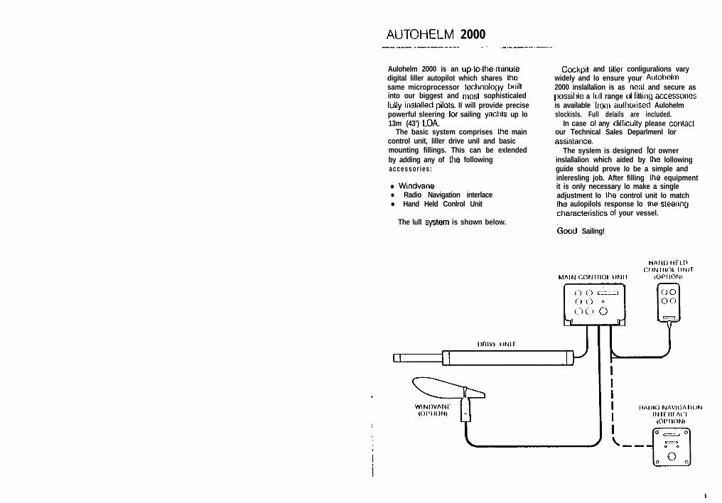
The basic system comprises Ihe maincontrol unit, liller drive unil and basicmounting fillings. This can be exlendedby adding any of Ihe followingaccessor ies :
l Windvanel Radio Navigation interlacel Hand Held Conlrol Unit
The lull syslem is shown below.
Cockpil and loller conliguralions varywidely and lo ensure your Aulohclm2000 inslallalion is as neal and secure aspossible a lull range ol lillrng accessonesis available lrom aulhorised Aulohelmslockisls. Full delails are included.
In case 01 any dillicully please conlaclour Technical Sales Deparlmenl lorassislance.
The syslem is designed lor ownerinslallalion which aided by Ihe lollowingguide should prove lo be a simple andinleresling job. After filling the equipmentit is only necessary lo make a singleadjustment lo the control unit lo matchthe aulopilols response lo Ihe sleenngcharaclerislics 01 your vessel.
hood Sailing!

INSTALLATION
DRIVE UNITThe drive unil is mounled belween thetoiler and a single allachmenl poinl on theyacht’s structure. After connection to theyacht’s 12 volt electrical system the unitbecomes operational.
For correcl installation two basicdimensions are critical (Fig.l):-
Dimension A = 620mm (24.5”)mounling socket lo tiller pin
Dimenslon B = 460mm (16”)rudder stock cenlre line to tiller pin
Clamp Ihe tiller on the yacht’s cenlreline and mark elf dimensions A and B (Ais measured on the STARBOARD side ofthe cockpit) using masking tape to locatethe fixing points. Ensure themeasurements are at right angles asshown.
The drive unit must be mountedhorizontally.
SLOPING RUDDERSTOCK
In certain circumslances it may be more (/convenient to mount the unit on lheporthand side. When this is the case, thechangeover switch will requireadjustment as lollows. Use a screwdriverto rotate lhe switch anli.clockwise untilthe endstop is reached (Fig. 2).
I Never force the changeover switch,light pressure only Is required.
PORTHAND MOUNTING
2

BASIC INSTALLATIONAlter eslahlrshrng Ihe conlrol dimensionsthe Aulohelm 2000 can usually bemounled drreclly onto the Starboardcockprl seal (Fig 3). Proceed as lollows.
TILLER PIN (Cal No. 0001)l Drill 6mm (l/4”) hole x 25mm (1”)
deep al porn1 marked.l Using a Iwo parl epoxy adhesive such
as Araldile, bond the tiller pin intoplace .
l Position Ihe shoulder 01 Ihe pin -125mm (r/z”) above Ihe liller surlace.
MOUNTING SOCKET(Ca! No. D602)0 Drill 12.5nlrn (l/2”) hole x 25rnrn (1”)
deep inlo Ihe starboard cockpil seal.
II Ihe slruclure thickness al Ihemounling posilion is less Ihan 25mm(1”) carelully reinforce Ihe undersurface wilh a plywood plale bondedinto posit ion.lnslall the mounling sockel using Iwopar1 epoxy adhesive.
Note The aulopilol is capable 01generating high pushrod loads. Ensurelhal:-l The epoxy is allowed to harden
Ihoroughly before applying any loads;l Ail holes are drilled to correcl size and
where necessary reinlorcing isprovrded.
MOI.INTING SOCKET TILLEII PIN
INSTALLATION PUSHROD EXTENSIONS (Fig.4)ACCESSORIES The prrshrod lengllr IWI~ be simplyII il is not possible lo inslall Ihe drive unildirectly onto Ihe cockpil seal or tiller asdescribed, one 01 the lollowingaccessories (or combinalion) will ensurea perfect inslallalion.
exlended using one 01 Ilre slandardpushrod exlensions. Drrnension C IS
modified as lollows:-
Dimension C Pushrod Extekion Length L Cat No.. _ _ ._ __ _622mm (24.5”) Sld Dimension’ ---.....-.. ----.-..--.-- .-.. -.--- . ..--__- __._ ._.. _ --.- - ._... _~_ ..__ .-.- ..-~-..- -646mm (25.5”) 25mm (1”) 0003_ _ _673mm (26.5”) 51 mm (2”) DO04--_ ^--....-........- __ -....-.- - -...--... ..___...._... -...- _~- ____._...........699mm (27.5”) 76mm (3”) DO05_ .--. . . _. _. _ - . .._._. ..- .- .___ __--_-... --..724mm (26.5”) 102mm (4”) 0006749rnrn (29.5;;) -- 127mm (5”) Dcro7~-
775rnm (30.5”) 152mm (6”) DOOa..._ .- . ..__..._. -..-- ._ _. -- ~.._ ._.._.......____..._
FICJ. 4

TILLER BRACKETS (Figs.5 and 6)Where the herghl 01 Ihe loller above orbelow Ihe cockpil seat or mounting planeis such lhal slandard mounling is notpracticat a range of tiller brackels allowsthe loller pin o&et lo be varied.
Installationl Posilron the tiller bracket on Ihe cenlre
line (upper/lower) 01 the tiller andeslablish lhe control dimensions Aand B.
l Mark oil Ihe position 01 the cenlres ofIhe Iwo Itxing boll holes.
l Drill Iwo 6mm (Y4”) diamelerclearance holes through Ihe cenlreline 01 the Irtter.
l Install Ihe liller bracket using 2 x 6mm(I/J”) diameter bolls, nuts andwashers.
0 Bond lhe lixing bolls in place wilhepoxy adhesive and fully lighlen thenuts.
SLOPING TILLER
.._.. .- _ . . . -..- -._ ..~Dimension Cl (below litter) Dimension E (above litter)
25mm (1”) 5 1 nw1 (2”)
5tmm (2”) 76mm (3”)_-. ______ __ ..- _______. ___.. -..-... . -76mm (3”) I ..-._ 1 0 2 m m (G)
102mm (G)
Cat No.
0006
DO10
DO11 -. ..
127mm (5”) 0012
.127mm (5”) 152mm (6”) DO13._-._. _ _ _.. ~_ ._.__ --. __~__.-------_-_
6

CANTILEVER MOUNTING (Fig.7)Where II is ncccessary lo nllach Iheaulopilol lo a verlical lace such as thecockpit srdewall a canlrlever sockelassembly is used.
The maximum exlension ollsel is254mm (10”) and Ihe canlilever can beGUI IO the exact lenglh necessary duringmounting.
installation0 Clamp the tiller on the yachl’s cenlre
line.l Measure dimension F (aclual)l Refer lo table lo eslablrsh cutling
length lor cantilever rod.
_______._____ - _.-.._-_-._-_--Dimension F Cut Length L
686mm (27”) I 51 mm (2”).__ .._.. ._ _.._~71 lmm(28”) 75mm (3”)
-. 737mm (29”) 102mrn (4”)
762mm (30”) 127mm (5”)_~. ._. .-__. _-. .-.-. ---.. .- -----..--- .- -.787mm (3 1”) 152mm (6”)_ - _._. _ _ _ --.8 13mm (32”) 178mm (7”).-..- _. _~ -.. _-. ..- . . ..- --- -838mm (33”) 203mm (8”)
0 Cut cantilever rod to length L using ahacksaw.Measure from threaded end.
l Remove burrs with He.0 Tr?rriporarily assemble the cantilever
by scrcwrrlg the rod into the mountingIlange.
l Ensure lhe drive unit is horizontaland mark oil Ihe location ol themounting Ilange.
l Mark and drill 3 x 6mm (V4”)clearance holes (ignore the two innerholes).
0 Mount the llange using 3 x 6mm (l/4”)
diameter bolts wilh nuts and washers.Be sure to install the backing platecorrectly. Bed the flange on a thin coalof silicone sealant.
l Screw the rod lirmly into place using atommy bar.Roughen the end of the rod and theinside 01 the cap to provide a key.Apply Ihe two part epoxy adhesiveprovided to the rod end and cap andplace the cap over the rod end.Ensure the hole lor the drive unitmounting pin is lacing up.Allow the epoxy adhesive 30 minutesto lully harden before applying anyload.
When the Autohelm is not in use thecomplete rod assembly may beunscrewed, leaving the cockpitunobstructed.
_ -_..._ ._ F--.. ---_ .--.. .-__ -,
9
;/

PEDESTAL SOCKET MOUNTINGII may be necessary lo raise the hcrghl otIhe Aulohelrn mourrliny sock& above Ihemounting surlace. For this a pedeslalsockel assembly is used.
Selectionl Lock Ihe lilter on the yacht’s cenlre
tine.l Establish the slandard control
dimensrons A and B.l Measure dimension G (Fig.8)
ensuring Ihe Aulohetm aclualor ishorizontal.
0 Setecl lhe appropriale pedestalsocket assembly from Ihe tableshown.
Installation /l Mark oft Ihe position 01 Ihe mounling
llange on Ihe cockpil seal or counler.
l Ensure that control dimensrons A andB are corrccl
l Mark and drrtt 3 x 6mm (VI”) dramclerclearance holes (ignore Ihe Iwo innerIroles).
0 Mounl Ihe ltange using 3 x 6mm (I/q”)diameter bolls, nuls and washers,being sure Ihe back ptale is installedcorreclty. Bed Ihe ltange on a thin coat01 silicone rubber sealanl (Frg.9.)
l Screw Ihe mounling socket lirmty inloplace.
When lhe Aulohelm is nol in use Ihemounling sockel may be unscrewed loleave Ihe cockpit unobslrucled.
Dimension G Pedestal Socket Length L Cat No.
38mm (1.5”) Std. Dimension -__-_---_-. --- - --_ --_. ._ _ ._ _ __.-__- .-- .________._.....___._
76mm (3.0”) 38mm (1.5”) DO26
69mm (3.5”) 50mm (2.0”) DO27- -.... - -_- . --..102mm (4 .O”) 64mm (2.5”) DO28
114mm (4.5”) 76mm (3.0”) DO29 --_... - _..._.. -__ ._ . _ .~ .._. _. _ .__ __ _ _. ._.. ._ -. --_. ___....127mm (5.0”) 89mm (3.5”) DO30
TILLER PINSFor cerlain non-slandard inslattations erange 01 litler pins is available.
Description Sire Cat No...--. - ___......____ -_--_-------- . . - ..-. - ..-- .-___-._--. __._ -_- _____.Small lhreaded titter pin 25mm (1”)..-.----.- DO14._.-.. .._._.. ..--.Extra length tiller pin 72mm (2.8”) DO20-_.-----_- ._.__.__ -___ _.--__ ____. -..------ ___._..Extra lenglh lhreaded tiller pin 72mm (2.8”) D O 2 1
10 11

CONTROL UNITThe conlrol unit slols into a permanentlymounled socket sited in the cockpit IIcontains a gimballed fluxgale compassand Iherefore has some reslriclions onmounling posilion.
The control unit should be siled whereit can be operated easily horn Ihesteering positron. It should also beposilioned al leas1 60cm (2’6”) awaylrom lhe main steering compass lo avoiddevialion of both compasses.
Deviation of the control unit fluxgalecompass is less imporlanl since
headings are always adjusted byreference lo the main sleering compass.Nevertheless, deviation should beavoided if possible and thus the conlrolunit should be siled as far away fromother magnelic or iron devices aspraclical.
Having selected the besl mounlingsite, the mounling sockel may besecured lo a convenient wooden or glasslibre surface using the self lappingscrews provided. The mounling surfacemay slope away from verlical by amaximum of 459
Battery ConnectionThe waterprool ‘Dri-Plug’ srrppliedshould be silualetl as close as possible loIhe Aulohelm 2000 lo minimise leadlength. The Dri-Plug sockel musl beconnecled directly lo the vesselselectrical dislribulion panel and on noaccount paralleled into exisling wiring forother equipment.
The Aulohelm supply must beindependently switched and protecledby a 5 amp fuse or current trip.
Since the autopilot is microprocessorbased il is very imporlant lhat vollagelosses in supply cables are minimised.
Supply cables sl~oulcl Iherelore he asshorl as possible and 01 no less size Winsl~own in Ihe lollowirg lable.
The brown wire of the Autohelm 2000lead should be connecled lo positive. IIconnections are accidenlly reversed IheAulohelm 2000 will nol operate bul nodamage will result
Lead Length Cop&r Area
-.tJp to 25m (6’) 1 .Omm*
UP P!vF! (‘3’1 _ _ .__ __ !:?mmf.. - -...up lo 65m (22’) 2.5mm2_ __ __ _-- ..------.- ..------
Accessory ConnectionIn common wilh all Ihe Aulohelm 2000’saccessories, the drive unit plugs inlo Iheconlrol unit lo facilitate slowing andservicing. To ensure reliable connectioneach plug incorporates a locking ringwhich should be turned clockwise losecure.
Although each accessory has aunique socket and cannot bemisconnected, Ihe drive unit should beconnected lo Ihe sockel marked Helm,Ihe windvane to Ihe socket marked Vaneand the hand held remole conlrol lo Ihesockel marked Remote.

OPERATION
WINDVANE ATTACHMENT \ \ I I!, I .ITIE w~ndvane atlaclrrrrcnt is normallyniounled cenlrally on lhe alter rail whereit can be sited in clear wrnd on bolhlacks. The windvane mounting masl isclamped lo Ihe aller rail by Ihe Iwo ‘U’bolls provided (Fig.12). Theinlerconnecling cable should be broughlIhrough Ihe slol lo allow Ihe windvanehead to be plugged into Ihe lop 01 Ihemasl (Fig.13). The inlerconnecling cablecan lhen be run back and plugged inloIhe Aulohelm 2000.
Note The windvane head is suppliedwith Ihe vane detached for ease ofpacking. The vane is easily assembled lolhe head and secured by means 01 lhecirclip provided (Fig.14). Care should belaken lo ensure that the small circlip iscorreclly locqled inlo lhe groove.
14
BASIC PRINCIPLESm lollowing descriplion 01 Ihe Aulohclrn2000’s principle of operalion will help youlo make lull use 01 ils advanced lealures.
The powerful combirralion of a Iluxgalecompass and microprocessor conlrolprovides ‘aulolock’ course selectionlogelher wilh precise push-bullon courseadjuslmenl.
Deviation from course is continuouslymonilored by a sensitive fluxgatecompass and correclive rudder isapplied lo relurn lhe vessel lo course.The applied rudder is proporlional locourse error al any lime and lhus whenIhe course is restored Ihe rudder will beneulra l ised.
When changes in vessel lrim occurdue lo varialions in wind pressure orengine Itirollle selling lhe course canonly be rnainlained by Ihe applicalion 01permanenl rudder oif-sel (standing helm)lo reslore balance. II permanenl rudderoll-sel is nol applied lo restore balancethe vessel will bear on lo a new heading.Under lhese circumslances Ihe
Arrlol~elm 2000 clclecls llial Itie origrnalcourse is nol berng reslored andconlinues lo apply addrlional rudder oll-scl in llie appropriale direclion urilil thevessel relurns lo Ihe origirral treading.Aulomalic lrimming capability ensuresthat Ihe originally sel course is heldirrespective of any changes in balanceIhal may occur during Ihe course 01 apassage.
The Aulohelm 2000’s computer alsocontinuously monilors Ihe pallern ofapplied rudder correclion and candist inguish unnecessary repet i l ivecorrections caused by prlch and roll ofIhe vessel lrom those necessary IOrnainlain Ihe selecled heading.
The computer will automatically, neglecl all unnecessary correclions soIhal aulopilol aclivily and powerconsumplion is conlrnuously oplimisedal minimum levels.
The high degree of control aulomalionmade possible by the micro compulersimplilies user control lo a series 01 pushbulton operations.

KEYPAD OPERATIONFull conlrol of Ihe Autohelm 2000 isprovided via a simple six bullon key pad.
The basic control functions are astallows:-
When the aulopilol is swilched on il wiltalways star1 up in Stand by mode. InStand by mode Ihe pushrod can beexlended or relracled lo engage wilh Ihetiller pin using the four black bullons.
t,0.ul0
ii ii Push and hold down loexlendlrelracl Ihe pushrod.
AUTO Push once lo engage the aulopilotlo mainlain Ihe currenl heading orpush twice (wilhin 2 seconds) loreturn lo Ihe previous aulomalicheading.
66Push lo aller course lo port (-) or
- 1 0 4-10slarboard (+) in incremenls of 1and 10 degrees.
STAN Push once lo disengage Iheautopilot and relurn to Stand bymode.
(The previous automatic headingwill be memorised).

-- __. _ _ _ _ _
WINDVANE SYSTEMPcrlormance under windvano has beenimproved by Ihe inlroduction of WindTrim.
Wilh Wind Trim the compuler uses Ihefluxgate compass as the primaryheading relerence. However, as changesoccur in the apparent wind angle thecompuler automatically adjusts Ihecompass heading lo maintain Ihe original
apparent wind angle.This syslcm eliminates the ellecls 01
turbulence or shorl term wind varialionsand provides smooth preciseperlormance under windvane withminrmum current consumption.
When a wrndvane syslem is lilled. anew layer 01 control funclions isaulomatically opened as follows:-
Push both red keys togelher onceto engage the windvane andmainlain Ihe currenl apparent windangle.orPush both red keys logelher twiceto return lo Ihe previous apparenlwind angle.
__--- - - -
Push once to alter the vessel’sheading relative lo the apparentwind in increments of 1 or 10degrees.Note + keys always turn the vesselto starboard.
- 1 0 +10
a 0
STAND BY
0AUTO
0
Push once lo disengage Ihewindvane for manual sleering. (Theprevious apparent wind angle wiltbe memorised).orPush once to change over to ,aulomalic compass headingcontrol and maintain Ihe currentheading.
AUTOTACK FUNCTIONThe Aulohelm 2000 has an automaliclacking lunction which operales in bothcompass and windvane mode aslollows:-
Push -1 and -10 keys logelheronce to iniliale a tack to port.,
0-
+1
-The Aulo Tack function operales byselecting a preset course change(100”) to bring Ihe vessel onlo theopposite tack.
During the tack, the Of1 CourseAlarm may sound. This indicatesthe autopilot is adjusting trim toacquire the new course.
On completing the tack andhaving sheeted and retrimmed the
Push +l and +lO keys togelheronce lo initiale a lack to starboard.
sails, the vessel rnay be broughtonlo Ihe desired apparenl windangle by line adjuslmenls lo lhecourse using the t/-lo keys. Noadjustments should be madewithin 1 minule of compleling thetack to allow the Autopilot tocompensate lor the helm trim onthe new tack.
19II

OPERATING MODE INDICATIONThe operating mode of Ihe Aulohelm2000 is indicated by a flashing LED asfollows:-
OPERATING MODE LED FLASIHING CODE
STANDBYEnables Ihe pushrod lo bepositioned over the tiller pin and 1 I Iprovides power sleenng.
AUTOAutopilot steers to maintaincompass heading.
- - -
WINDVANEAulopilol sleers lo maintainapparent wind angle. Windvanemode is also confirmed by a single -mliow
beep tone emitled every 30seconds.
Hand Held Control Unit
An optional hand held conlrol unit can beplugged inlo Ihe control unil to provide
(Cat No. 2076)
full course change capability fromanywhere on board. The unil duplicatesthe main control units four coursechange keys and may be used in bolhStand by and Auto modes. Theoperalion of the main conlrol unil isunchanged when Ihe hand held conlrofunit is connecled.
‘IIll:; llllOllilCX! lll;ly IX? IlWtl will1 iIl\y riltftl>
Radio Navigation Interface
IliIVI~)kIIlOIl SySl(?llt Ill;\1 Olllfl~llS crossIrack crlor lo olllicr IIIC NMEA Olt10, OltK?
(Cal No 2075 .- MMEA lormal)
or 0183 slailtlartl. II sufX!rvisos II1eAII~~II~II~I 2000 lo inainlniil Ihcf)l~!:;(!lC!c:lC!C I IliK~lt WI 011 II I(! raclloI I~.A~~~~I~II sysloi~i. hll of kmlrlg tlchrlsiirc :;i~f~~hxl wilh mcli inicrface*
Yt~tr III;III\ (11:;hd NIIOI or NiIlIl(X:ll’~I’rocli~c:l Sirfqboi I f.h:fx~~l~~~~!~ll wlfl 110 alhIO ;1(lvlsti YOII 01 f3~1tl10 NZIVI<);UI~IISySlC!lll!; Wlll1 Sllll~ll~lO illllOflllOl C~lllf~lll.
FUNCTIONAL TESTPROCEDUREAfler compleling (he ins(allalion youshould carry out the following lunclionallesl lo familiarise yourself wilh Ihe syslembefore allempting sea Irials.
Plug Ihe Aulohelm 2000 inlo Ihe powersockel and switch on Ihe eleclricalsupply. The unit will emit a short beepLone lo indicale lhat it is aclive and (heLED will flash to indicate Stand byoperaling mode.
Ensure the mounting pin is engaged inthe socket. Using Ihe four course controlkeys to extend or relracl Ihe pushrodposilion the end over Ihe tiller pin. Theunit will emil a short beep lone on eachpress of a key lo confirm valid enlries.Place Ihe pushrod end on Ihe liller pin,and press Ihe +lO key. The liller shouldmove lo porl. II the litter moves toslarboard, the changeover switch isincorredy set and musl be adjusted asdescribed on page 3.
Press Auto lo place the aulopitotunder compass control. The LED will betit constantly to indicale that Ihe unit is inAuto mode. If Ihe yacht is swingingaboul ils mooring, you will see lhat smallvariations in heading cause the unii toapply correclive action lo the rudder.Press Stand by lo relurn Ihe unit loStand by mode.
Rudder Control AdjustmentBefore allempling sea lrials Ihe rudder ’conlrol musl lirsl be adjusled lo Iheselling shown below.
This selling will provide stable controlfor inilial sea trials and may, if necessary,be fine luned later (see page 25).
20 21i/ ”

SEA TRIALS_- _....._ _. _. ..-. -.. -- _.-. __.. ’ .
lnltial sea trails should be carried oul incalm conditions with plenly 01 sea room.The previously conducled functional leslwill have verified lhal Ihe aulopilol isoperaling correclly and lhal you arefamiliar with all of its conlrols.
During lrrst sea trials. Ihe vessel will beconslanlly changing heading, and il is,Iherelore. very imporlanl lo mainlain aconstant look.oul.
The following initial lrial procedure isrecommended:-
@ Steer on to Ihe desired heading andhold the course steady.
l Using the lour course control keys,position and lhen place Ihe pushrodend over Ihe lillcr pin.
0 Press Auto lo lock on lo Ihe currenlheading. In calm sea conditions aperfectly constant heading will bemaintained.
l Aller course lo porl or slarboard inrnulllple incrcmenls of 1 and 10degrees.
Power Steeringl Press Stand by and praclice power
steering using the four course conlrolkeys.
l Press Auto lwice (wilhin 2 seconds) loreturn to Ihe original automaticheading.
Hand Steeringl Press Stand by and Ml the autopilol
lrom the tiller pin lor return to handsleering.
Automatic Sea State ControlDuring the sea Irial. the operation 01 theautomatic sea stale conlrol can beobserved. When the aulopilol is initiallyengaged in Auto mode the aulopilot willrespond lo all pilch and roll movemenls.During the lirsl minule of operation, it willbe noticed lhat repetitive movements ofthe vessel are gradually neglected untillinally the aulopilot will respond only lotrue varialions in course.
To ensure accurale course adjustmentthe sea stale control is automatically resetwhenever a 10 degree course change isexecuted.
Sea State tnhibitWhere maxmum course keepingaccuracy is required the automatic seastale control may be inhibited bypressing -1 and +l keys together once
Autopilot aclivity and lherelore powerconsumption will be increased but
, course keeping accuracy will bemaximised.
The automatic seaslale control isreslored by pressing the -1 and +l keystogether.Note Engaging the autopilot (pushingAuto) or engaging the windvane (bothred keys logelher) will always reslore theautomalic sea state conlrol.
i22

_.--..--.~ - - - --
Auto-Tack FunctionThe following addilional trial isrecommended:
Steer onto a constant headingapproximately loo free of closehauledPress Auto to lock onto the currentheading or bolh red keys lo lock OnlOIhe apparenl wind if a vane is filled.
l Decrease the apparenl wind angle(using the +l key if on the slarboardlack) unlil the yachi is sailing closehauled al oplimum penetration.
l Prepare to lack and then press Ihe + 1and +lO keys together (if on thestarboard lack) to initiate a lack IO
slarboard.
l The yacht will complele a 100° coursechange IO bring it onto Ihe oppositelack.
WINI)
v
1v.
On compleling lhe lack and havingsheeted and retrimmed Ihe sails, thevessel may be brought onlo the desiredapparent wind angle by fine adjuslmenlslo Ihe course using Ihe +ll-lo keys. Noadjuslmenls should be made within 1minute of compleling the lack lo allow theAutopilot lo compensale for the helm trimon Ihe new lack.
DisengagementThe pushrod is held inlo engagementwilh the lilter pin by Ihe weigh1 of theaclualor unit. This melhod ofengagement is secure and has beenadopted for safely reasons lo allow Ihe
* pushrod lo be easily disengaged whenmanual override becomes necessary.
w OFF-COURSE ALARMWhen the autopilot is set lo either Auto orVane mode a built in off-course alarm isaulomatically sel up. The off-coursealarm will sound when the vesseldeviales for any reason from the originalcourse by more than 15 degrees for over10 seconds. II is denoled by a continuousseries of bleep lones.
The alarm will be silenced if the vesselreturns to within 15 degrees of theoriginal course.
In Auto, if the vessel does not returnwithin these limils the alarm can only besilenced by selecting Standby.
In Vane, the alarm will sound when thewind direction changes by more lhan 15degrees and may be accepted bypressing bolh red keys together. This willsilence the alarm and advance Ihe offcourse alarm datum to the currentcompass heading.
CURRENT LIMITING AND. CUTOUT
If the autopilot is driven into its end stops,Ihe drive will be pulsed lo prevent
. overloading Ihe motor. If the pilol is left inthis condition for 30 seconds themicroprocessor will aulomalically cut outpower to the motor and sound the alarmcontinuously.
To restore the autopilot for normaloperation the standby key must bepressed lo put Ihe unit in standbyoperating mode.
Rudder Control AdjustmentThe rudder conlrol settingrecommended on page 21 will provideslable control for inilial sea trials.However, sailing crafl can vary widely intheir response lo the helm and furtheradjustment of Ihe rudder control settingmay improve Ihe Autohelms steeringcharacteristics.
An excessively high rudder controlselling results in oversteer which can berecognised by Ihe vessel swinging slowlylrom side lo side of Ihe aulomalicheading accompanied by excessiverudder movemenl. In addition, distinclovershool will be observed when Ihecourse is changed. This condition can becorrected by reducing the rudder controlselling (rolaling rudder control anti-clockwise).
Similarly, an insufficient rudder controlselling results in understeer which givessluggish sleering performance and isparticularly apparent when changingcourse. This is corrected by increasingIhe rudder control selling (rotatingrudder control clockwise). Theselendencies are most easily recognised incalm sea condilions where wave acliondoes not mask basic sleeringperformance. The rudder control settingis nol over critical and should be sel loIhe lowest selling consislenl withaccurate course keeping. This willminimise actuator movements and hencereduce power consumplion.
25i t

OPERATING HINTS- -~--_._--______---___------- -_-~_
The Aulohelm 2000’s computercontinuously optimises automalicsteering performance etiminaling theneed lor operalor supervision.
II is, however, very imporlanl loundersland the effect of sudden trimchanges on steering performance. Whena sudden change in lrim occurs theautomatic trim compensation systemrequires approximately 60 seconds toapply the necessary rudder off-set torestore the aulomalic heading. In guslingcondilions, therefore, the course maylend lo wander slightly. particularly in Ihecase 01 a sailing yachl with badlybalanced sails. In Ihe laller case, asigniticant improvement in coursekeeping can always be obtained byimproving sail balance. Bear in mind thefollowing imporlanl poinls:-
l Do not allow the yacht lo heelexcessively.
l Ease lhe mainsheel travetler loleeward lo reduce heeling andweather helm.
0 It necessary reef the mainsail a tillleearly.
II is also advisable whenever possiblelo avoid sailing with the wind dead asternin very slrong winds and large seas.Ideally, the wind should be brought alleast 30° away from a dead run and insevere conditions il may be advisable toremove the mainsail altogether and sailunder headsait only. Providing lhesesimple precautions are taken theautopilot will be able to mainlaincompetent control in gale forcecondilions.
It may be noliced Ihat ltre autopitoltends lo be a litlle less slable on northerlyheadings in the higher lalitudes of ther~orllrerr~ hemisphere (and corivcrsclysoutt rerly headings in the southernhemisphere). This is caused by theincreasing angle of dip of the earlh’smagnetic field at higher latitudes whichhas the effect of amplifying rudderresponse on northerly headings. Thetendency towards norlherty headinginstability is usually more obvious alhigher speeds and when it occurs canbe corrected by reducing the ruddercontrol selling.
Passage making under automatic pilotis a very pleasant experience which canlead lo the temptation of relaxingpermanent watch. This must always beavoided no malter how clear the sea mayappear to be.
Remember, a large ship can travel Iwomiles in five minutes -just the lime it takeslo make a cup of coffee!
TOTE BAG (Cat No. D089)A special zip top padded bag made fromlough PVC is available lo prolecl andstow your Aulohetm and is available fromAutohetm slockisls.Warn ingl Do not slow your Aulohelm in a locker
liable to flooding by the bilge water.0 Do not leave your Autohelm in a damp
locker over the winter lay up period.
MAINTENANCEAll moving parIs. the system have beenlubricated for life at the faclory. Thereloreii0 mainlenance whatsoever will berequired. Should a lault develop Iheautopilot’s plugabilily ensures that onlythe defective unit need be returned.
Before lhis is done please doublecheck that the power supply cable issound and that alt connections are lightand free from corrosion.
Since Ihe control unit is lhe mostcomplex, there is a very high probabilitythat if a fault has occurred it is in this unit
.
-.----z.-p-
which should therefore be returned forrepair, which wilt be carried out speedilyand al moderate cost. The drive unit hasp10va11 lo be extremely reliable and isvery unlikely to develop a fault. If howeverthe drive unit is suspecled of being faultyit may be checked by connecting 12Vacross the sockets al the end of the driveunit cable and ensuring the motor runsnormally.
In Ihe case of a sailing yacht fitted witha windvane system if a fault occurs onlyin vane mode then it is likely lhal a faulthas developed in the vane head.
LIMITED WARRANTYNaulech or ils appointed Distributors orService Cenlres will, subject lo Ihecondilions below, rectify any failures inthis producl due to faully manutacturewhich become apparent within two yearsot its puchase date.
Equipment used in lhe country ofpurchase should be sent directly to theaulhorised Distributor for that counlry orits appointed Service Cenlres. Theproduct will then be serviced lree ofcharge and returned promptly direct tothe sender.
Equipment used outside the country ofpurchase can be eilher:-a. Returned to the Distributor or Dealer
in whose country or from whom Iheequipment was originally purchased -it will then be serviced free of chargeand promptly returned direct to thesender , or
b. The product can be relurned freightpre-paid to the authorised Dislributoror its appoinled Service Centres in thecountry in which the product is beingused. II will then be serviced andreturned direct lo the sender on thebasis that the Distributor or ServiceCentre will supply any parts used freeof charge but the sender will beinvoiced for the necessary labour andreturn shipment at the local rate.
CONDITIONSThe warranty is invalid if:-a. The product has been misused,
installed or operaled not inaccordance with the standardsdefined in this manual.
b. Repairs have been attempted bypersons other lhan Nautech approvedServ ice personne l .
AFTER SALES SERVICE Centres. You will find a list enclosed.Should for any reason your Autohelm Each service cenlre is trained and2000 require attention ensure that youreturn it lo one of the Authorised Service
equipped lo provide expert allenlion toyour Autohelm 2000.
/ 26

_... _-- ..-
SERVICE CENTRES - UK, Eire and Channel Islands -
tiamprhtre0 2 4 3 3 7 8 3 1 4
-.,\’
Isle of Wighl
(’ I,>‘, Cecmac Marine Ehxtre4Ccs( $ .2 A”CdSl.3 Mame
Cl-WCSlow0983 293996
5 Lymtngro”lPoole(’ .)\I Grcenhrm Marine Lid
’E!.-? thng Saltcr”r lane
I ymu~qto”Ilampstlw0590 75771
Greenham Marine Ltd011.y ‘NW M.w”a2 3 west ally RoadrodrDcisel0202676363
Marine Eleclrontcs SystemsrmdgcBuckland Brewer8uleloldNorth Dew”0805 22870 c o Antnm
O96Q3 65565Ocean Marine Servicer43 aw”“riePl~“KXlllI0752 2 3 9 2 2
Quay Electrtcs (TeignmoutlJ LtdIl”‘\.ut,,4,
Dublin 11000134259C1
( ?.‘IE
:a
Dale Sail ing Co LtdDakIlavcrto!d Wnll)“hlMr( 65 349
IIPollw1 tIPlbw,t4Jllhd#0758613193
Sailtronk MarineCtnrrctlSlrcl?lGLm Cmwy,cohyn nayc‘w0492 68 536
SCdhWll~Strdd”ll059588645
Robbins Marine Radio Sew&r
l&$glZ& EkCtrO”ks
‘ . tw tdgafSwth Qwwateuy
051709 5431 Edmburgh0313314343
Rtder SewterGk”blwkP.lwgC westCoCmk1tlol532184 III6
Ayrrtlac0292 315355
Jell Rulherlard
Electronic ServicesLargr Yacht Have”llvule RwdbtgrAyvshwe0475686091
28 ,, 29

OVERSEAS REf%ESENTATlVES__ _ - 1. -.-. _... -.- --
New ZealandLusly 6 illundell Limited89 Wait al RoadTakapunaAtat.la,,d IONew 2raLwdlrl (010 64 9) 444 3675lekr 007 74 60324 LUSlY N2rar (010 64 9) 444 3798NorwaySratronic AISI ,.,,.,k, I la.ld‘lgmJl 515OOMOSSNCWOyCl ~01047)92727331231272835kh IX?7 56 76547 SIRON Nrm (01047)9774152PortugalA . PereiralordaoRusdc k-wF~lk.w 152.1564cOO Put0 codexrorlugalId ~0103512)209479Irk-s 002 404 22308 IORDAOPFal tOlO3Sl 2)314169SingaporeCommunicat ions SystemsEngineering Pte Ltd67 Ayer lla,ab CrescenlO7.01Slngapore0513ld (01065)7765191Telex 007 87 23036 DEBEGPLFax: (010 65) 77 66795South AfricaCentral Boating Pty L imiteda1 ewe SIreelcap-2 Towll8OolSouth AIncaTel (010 27 21) 248026/7/Elcim 007 955 2G712 SAfar (tHOZ7 20242564SpainSit&aMlmtancr 44tlaKelor1.l IISp4lllTr1.(010343)3234315Telec 007 52 542l8YlEEfax:(010343)3235C62
Argcnlinrlrimrr S.A.I ,.,y I\ M ,lr‘,,ll r’t,*IMt,,475 Hlrnlw, nllnAIqPIIlIMlr, to10 5 4 I) 7 7 4 372Iv4470lv+” 3,117 1 21653 11041 It AIt
Canadalom laylor Co Ltd.I2 I,.v.w *wlrrlwcrltr~ MGK 31 IOlU?lllO
ltoornana’s ttnldeb,,a~tul~a~,),ii lt.VI’0 Ilo.N, 501?81305 AC Akwte I t&-xl~lnllalldId (010 3) 3240) 115141vk.r no744 70171 GllwNLId” IOIU3l 32401 II519Hong KongFar East Yacht SpecialislsLimitedM2 FloorBaskct-alk lhnae22 Ice I Iwse’SlrmtHong KongTd ~010852~525701515 229394Tekr 007 802 65925 KRtMA IIX
r .u>n kH w1tt t 4,b~)5ttl lnltkb. I”,, ,, ,x,5,41 I7 IOMIAYYCO ,011AUSlnlia
Solo Marine pty L td11 Gwen StreetRev&y N S W 2 2 1 2r\,lnrrlii114 (01061 2)7745255lel~r 007 71 127045 SOLMARAAFar (01061 2) 7745291AMIdaWwnw Ober.YacbtekktronikA 6”‘Il I mtrlm,Rn<lvAt,.lrv 3 8I%“,,,.,Id (Olfl43)55772419lax ,010 43) 5577 24195
far (010 1416)5304J45
Canary IslandsNotdert<Is hr<ln Bwwa 57Sallla CllP de Iclvtlkcanaly IsbMhTel (010 34 22) 284 871Tekx 007 52 92230 COON Ef.w(0103422)287311
CYPNSMcrcwy Divcrl Co. L imited53 $ymu AlaollzW sllwtI’ 0 Box 469lsr,awll(‘ypw,k-1 (010 357 51)65497Irk. 007 605 4976 MtRCOM CY
lng Hai Company LimitedPO 00x9 54lip0l‘lwwl& 10108862~5312088Tekx CXJ7 785 13951 VIRAGOFax (OIORB 62)5976531
II & 1 Marine Ekclronkr2 Bach Avenue
nlrkcyLrimpexM Rud,aw,,n, lckh,llaywtll!, hLrleslcad 1-7AffitKI Rnaktarklanbl,llvl ,010, lCi4GRR/161 01 32I,+. 00760726613 tRlMl1USASWWAutohelm AmericaNON wlullleki SlleeIGuillord. Cl 06437U S Alrl (010 I 2031453 8753Ma: 007 230643 804 IMIFax: (010 1203) 453 6109
lrl (twa354l)R4077k*lrx 007 501 2 334 MXIX ISlax 1010 3541)29323IsraelBriza Yacht & Marine SupplyICI Aviv P 0. Box 392321‘1.d
BarbadosC.O. Willialnr ElectrkalCo. L tdWaflPllS5.1 t&healLt.vbdalel (010 I809)425 2250T&-x 007 392 2366 COW WEla* (“IO 1 Em) 474 0374gcfgiumWert Diep Yachting Centrc SPRLR 8450 NwwpoonI <“lwwq 2BelqwlTel tO103258)234061Fax. (010 32 5815823 9246Bermuda
FinlandOy Marilim ABWtwrnl~k~imhe I51 - 00210,ldnnkiFuda,ulk-l 1010358lO673331Tckx 007 57 124788 MAR,1 SFFar-(010358)06927917
Td (010 9721320 259913284432lrlrx 265871
(“wts ICI 137AUR) MONRtF G
West GcrmanvFerropilot GM&2084 Relkngensiimnslrasse 3 5West GermanyTel (010494101)301240Telex-00741 218916OFEF’lDFax:(010494101~301214
I14yDeck MarineV~ak Cerdola 15520151 M1amnaly
FranceSD. Marine Eiectronique17-25 Rue Barian78500SartrowilkFrdl-Ke81(01033~l39146833Telex: 007 42 698347 SOMtLECFax (010 33) I 39t3 3022GibraltarSI-IVWBond lnrlrumentationThe l&kyxdG,blaltarId (010 350) 73701114,x 007 405 237.3 GlRltLI’bKFar: (010 350) 73726
West IndiesThe Signal LockerN&m’s DockyayardAhJlMWest krdrr1,-+t0101809)4631528lclcr (007393)2147/2119
lIYRIW1 II AKNAClllS AKFax.(0101809)4631524YugoslnvisMate NostrumY.?.cllhng C0nSUllUlgllorut Ciw.SamM Told 8 5opat1jaYugorlavlaTel ~0103851~713506T&x. 007 62 24215 IEHRI YU
Tel (010 392) 308 7229Telex- 007 43 353147 DECK IFax: (010 392) 301 3398
Marine Communications72 PIIB flay RoadPembroke HM 06BermudaTel 010 1809) 295-0558Tekr- 007 290 3795 MARCO LtAFar (010 I 8091292 0079BrazilFall YXhlSCnrlrol 5 A
JapanJ.&J. Limited2F lnago 0Mg 370) layam. - bhikiMnmKanagawalap1tllrk(OlO81)468761S~~Irlw 007 72 3RS2532 IMJIIW Ilax. 010 81468 76 1044
tndwlre E ComericoPOLlo.127KlS.lil F.l”lO - SPLlr.17dT@l (01055) 11 5211944Tekr 007 38 1124612 CNIO LtRFax- (010 55) 11 5482070British Virgin IslandsCay ElectronicsP 0 Box 345Road TownTortolaEhlnh vrgtn ItildsICI (010 180949)42400Iekx 007 255510 1006891 ESLUllFax 1010 1809 49) 44707
S&iH. Sletmsrd L Co.walnl;;tG4~raltarkl (010 350) 77183T&ax: 007 405 2324 MARtNA GK
ltipardlarvan L RipardIS6 14’xLwx Sr4lra1tY&l MallnaMaltaTrl (010 356) 35591Tekr WI 406 994 YOl5 MW
GreecePiraeur Electronic46 Aktl Mwts~louManna zeas185 36 F’iraeurGweceTel (010301)453 1027Ml817g7lck~OO76Ot74l219DORlGRFw(010 301)418 1091
Netherlands Anti l lesRadio-HollandCaribbean N VPO. Box 146PhQxlxIrg51. Ma;lltelNrlhcdands Ant&sId u)10599)522589fax (010 599) 522589
SwedenAxhede & HanrsonNva Wvvc.15b21 71V. FrdundaSwdmlrl. (01046311291111lclcx w75421447AX1lAsFax: (0104631)292789
3 0