“optical designs that amateur astrophotographers and ccd ... · amateur telescope making, book...
TRANSCRIPT

1
“Optical Designs that Amateur Astrophotographers and CCD Users should Know”
by Rick Blakley
8/26/2002
delivered at ALCON 2002, the Convention of the Astronomical League,
July 31 through August 3, 2002, hosted by the Salt Lake Astronomical Society
at the University of Utah, Salt Lake City
2
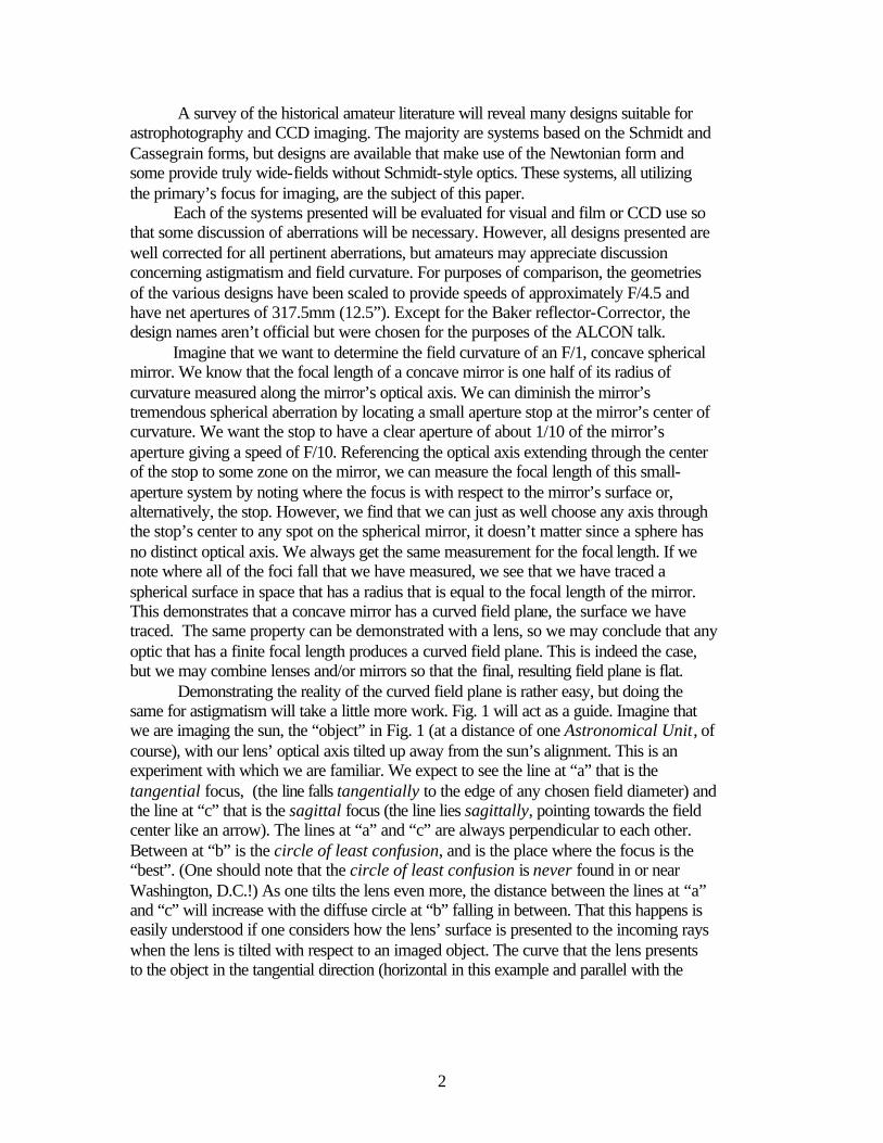
A survey of the historical amateur literature will reveal many designs suitable for astrophotography and CCD imaging. The majority are systems based on the Schmidt and Cassegrain forms, but designs are available that make use of the Newtonian form and some provide truly wide-fields without Schmidt-style optics. These systems, all utilizing the primary’s focus for imaging, are the subject of this paper. Each of the systems presented will be evaluated for visual and film or CCD use so that some discussion of aberrations will be necessary. However, all designs presented are well corrected for all pertinent aberrations, but amateurs may appreciate discussion concerning astigmatism and field curvature. For purposes of comparison, the geometries of the various designs have been scaled to provide speeds of approximately F/4.5 and have net apertures of 317.5mm (12.5”). Except for the Baker reflector-Corrector, the design names aren’t official but were chosen for the purposes of the ALCON talk. Imagine that we want to determine the field curvature of an F/1, concave spherical mirror. We know that the focal length of a concave mirror is one half of its radius of curvature measured along the mirror’s optical axis. We can diminish the mirror’s tremendous spherical aberration by locating a small aperture stop at the mirror’s center of curvature. We want the stop to have a clear aperture of about 1/10 of the mirror’s aperture giving a speed of F/10. Referencing the optical axis extending through the center of the stop to some zone on the mirror, we can measure the focal length of this small-aperture system by noting where the focus is with respect to the mirror’s surface or, alternatively, the stop. However, we find that we can just as well choose any axis through the stop’s center to any spot on the spherical mirror, it doesn’t matter since a sphere has no distinct optical axis. We always get the same measurement for the focal length. If we note where all of the foci fall that we have measured, we see that we have traced a spherical surface in space that has a radius that is equal to the focal length of the mirror. This demonstrates that a concave mirror has a curved field plane, the surface we have traced. The same property can be demonstrated with a lens, so we may conclude that any optic that has a finite focal length produces a curved field plane. This is indeed the case, but we may combine lenses and/or mirrors so that the final, resulting field plane is flat. Demonstrating the reality of the curved field plane is rather easy, but doing the same for astigmatism will take a little more work. Fig. 1 will act as a guide. Imagine that we are imaging the sun, the “object” in Fig. 1 (at a distance of one Astronomical Unit, of course), with our lens’ optical axis tilted up away from the sun’s alignment. This is an experiment with which we are familiar. We expect to see the line at “a” that is the tangential focus, (the line falls tangentially to the edge of any chosen field diameter) and the line at “c” that is the sagittal focus (the line lies sagittally, pointing towards the field center like an arrow). The lines at “a” and “c” are always perpendicular to each other. Between at “b” is the circle of least confusion, and is the place where the focus is the “best”. (One should note that the circle of least confusion is never found in or near Washington, D.C.!) As one tilts the lens even more, the distance between the lines at “a” and “c” will increase with the diffuse circle at “b” falling in between. That this happens is easily understood if one considers how the lens’ surface is presented to the incoming rays when the lens is tilted with respect to an imaged object. The curve that the lens presents to the object in the tangential direction (horizontal in this example and parallel with the
3
Fig. 1
line at “a”) is nearly the same as when the lens’ optical axis is aligned with the object. However, the curve that is presented to the incoming rays in the sagittal direction (vertical in this example and parallel with line “c”) is considerably different (it slopes more with respect to the incoming rays). The lens “looks” barrel or cylinder shaped to incoming rays depending on the tilt, and the foci show this. Most amateurs understand this phenomenon we call “astigmatism” but have difficulty understanding why any lens will show astigmatism when the lens’ optical axis is aligned with the object. The reasoning is very simple; most objects we observe are considerably larger than any lens or mirror that we image with so that most rays fall off-axis at some angle with respect to the lens’ optical axis. Any star grouping we observe is thousands of light years larger than our telescope’s entering aperture, so even though rays enter our telescope essentially parallel (the stellar grouping is so distant), our telescope receives most of the rays off axis at some real angle relative to the telescope’s optical axis. Thus, if our telescope/eyepiece system isn’t corrected for astigmatism, the characteristic tangential/sagittal lines will appear as we crank the eyepiece in and out because our telescope is tilted with respect to these off-axis rays. If we include a
4
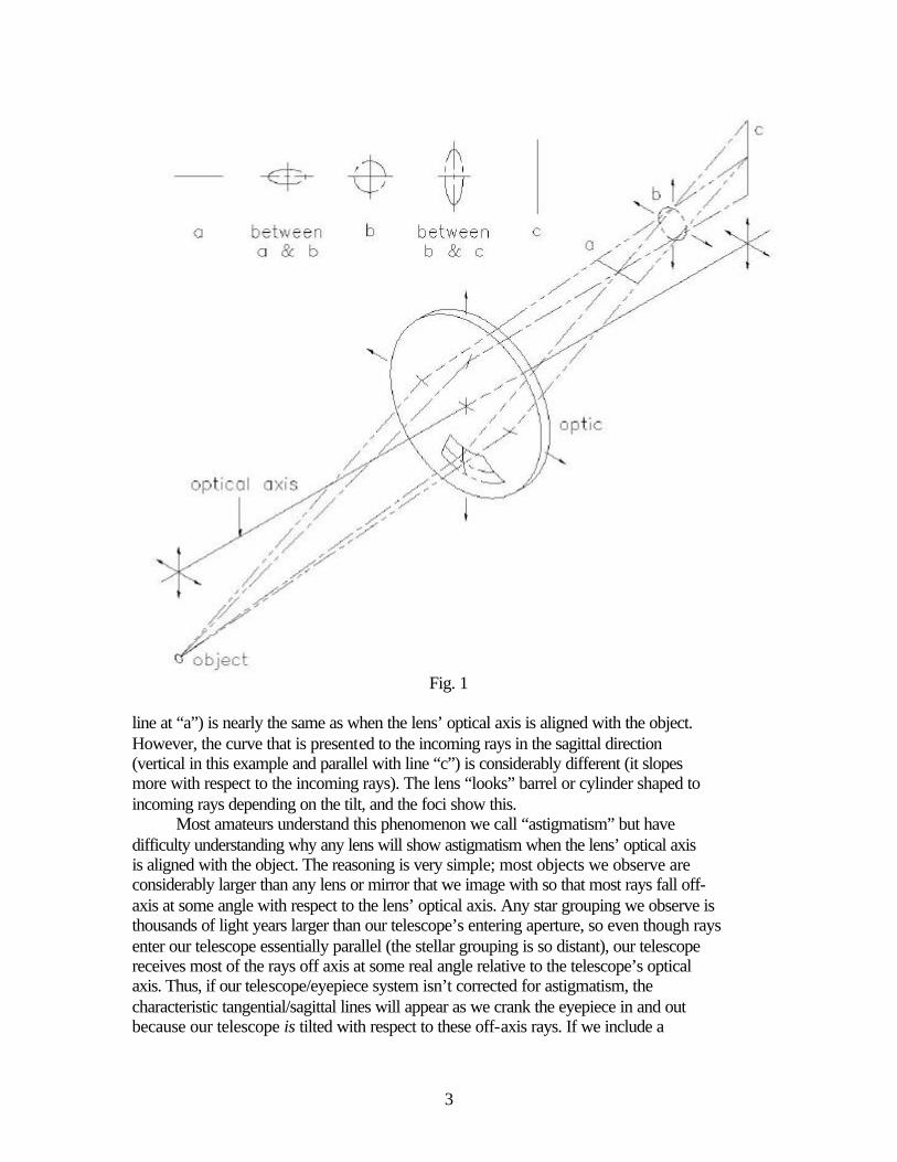
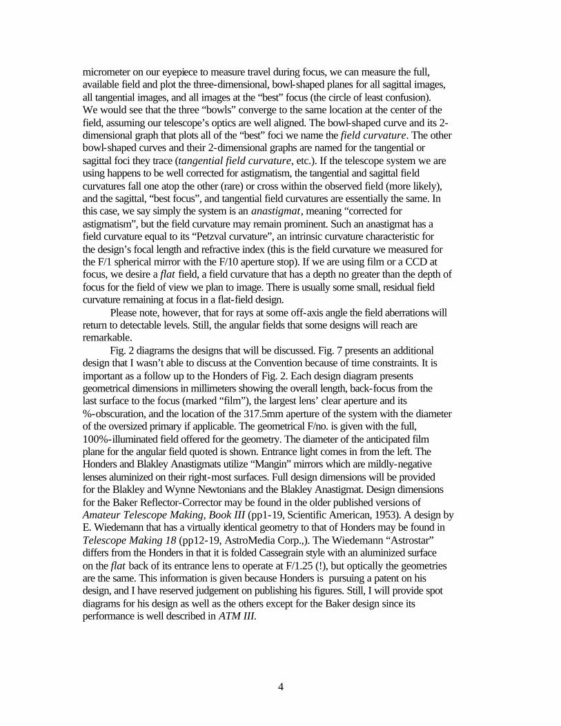
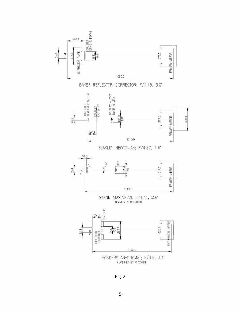
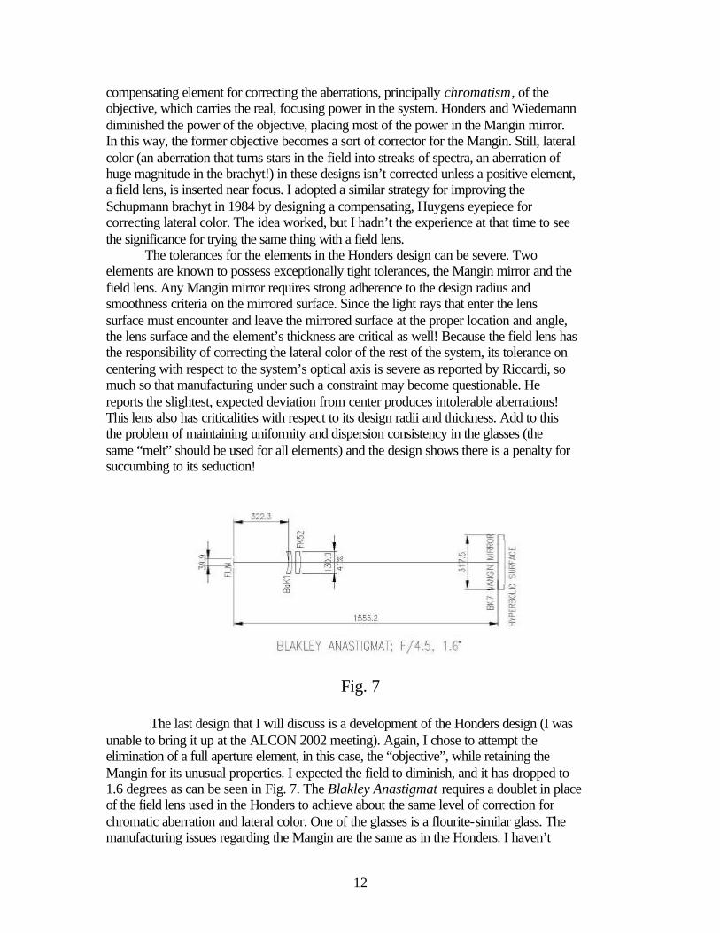
micrometer on our eyepiece to measure travel during focus, we can measure the full, available field and plot the three-dimensional, bowl-shaped planes for all sagittal images, all tangential images, and all images at the “best” focus (the circle of least confusion). We would see that the three “bowls” converge to the same location at the center of the field, assuming our telescope’s optics are well aligned. The bowl-shaped curve and its 2-dimensional graph that plots all of the “best” foci we name the field curvature. The other bowl-shaped curves and their 2-dimensional graphs are named for the tangential or sagittal foci they trace (tangential field curvature, etc.). If the telescope system we are using happens to be well corrected for astigmatism, the tangential and sagittal field curvatures fall one atop the other (rare) or cross within the observed field (more likely), and the sagittal, “best focus”, and tangential field curvatures are essentially the same. In this case, we say simply the system is an anastigmat, meaning “corrected for astigmatism”, but the field curvature may remain prominent. Such an anastigmat has a field curvature equal to its “Petzval curvature”, an intrinsic curvature characteristic for the design’s focal length and refractive index (this is the field curvature we measured for the F/1 spherical mirror with the F/10 aperture stop). If we are using film or a CCD at focus, we desire a flat field, a field curvature that has a depth no greater than the depth of focus for the field of view we plan to image. There is usually some small, residual field curvature remaining at focus in a flat-field design. Please note, however, that for rays at some off-axis angle the field aberrations will return to detectable levels. Still, the angular fields that some designs will reach are remarkable. Fig. 2 diagrams the designs that will be discussed. Fig. 7 presents an additional design that I wasn’t able to discuss at the Convention because of time constraints. It is important as a follow up to the Honders of Fig. 2. Each design diagram presents geometrical dimensions in millimeters showing the overall length, back-focus from the last surface to the focus (marked “film”), the largest lens’ clear aperture and its %-obscuration, and the location of the 317.5mm aperture of the system with the diameter of the oversized primary if applicable. The geometrical F/no. is given with the full, 100%-illuminated field offered for the geometry. The diameter of the anticipated film plane for the angular field quoted is shown. Entrance light comes in from the left. The Honders and Blakley Anastigmats utilize “Mangin” mirrors which are mildly-negative lenses aluminized on their right-most surfaces. Full design dimensions will be provided for the Blakley and Wynne Newtonians and the Blakley Anastigmat. Design dimensions for the Baker Reflector-Corrector may be found in the older published versions of Amateur Telescope Making, Book III (pp1-19, Scientific American, 1953). A design by E. Wiedemann that has a virtually identical geometry to that of Honders may be found in Telescope Making 18 (pp12-19, AstroMedia Corp.,). The Wiedemann “Astrostar” differs from the Honders in that it is folded Cassegrain style with an aluminized surface on the flat back of its entrance lens to operate at F/1.25 (!), but optically the geometries are the same. This information is given because Honders is pursuing a patent on his design, and I have reserved judgement on publishing his figures. Still, I will provide spot diagrams for his design as well as the others except for the Baker design since its performance is well described in ATM III.
5
Fig. 2
6
I begin with the Baker Reflector-Corrector because it is usually the oldest of the “modified” Newtonian types with which amateurs are generally familiar. Its primary is a parabola larger than the entrance aperture on the corrector plate if any significant 100%-illuminated field is desired. The doublet acts to correct the coma and astigmatism and flattens the field as well. However, the doublet adds spherical aberration that must be nulled with the corrector plate. The great advantage of the system is that one may use the primary as a classical Newtonian and then add the corrector plate and lens whenever wide-field photography is necessary. The largest example extant is the 20” corrector-plate aperture, 24” aperture primary mirror combination in use at the Dyer Observatory at Vanderbilt University in Nashville. Six degrees of well-corrected field may be covered with the design, but the geometry limits it to about three degrees at 100%-illumination. It is designed for use at 0.4341 microns in the violet, the sensitivity of older, silver plates. John Gregory has updated the design using modern, high-density glass in the doublet for film use in the more central, visual regions. The Baker Reflector-Corrector is an extraordinary design that sets a high standard for a visual/photographic convertible instrument. The Blakley Newtonian was my attempt to get the maximum field out of a traditional Newtonian using a strategy like Baker’s but designing without utilizing a corrector plate. I expected the well-corrected, maximum field to diminish once the corrector plate was eliminated, and that was indeed the case. The design was completed in 1992. I designed a simple doublet corrector, labeled “doublet & stop”, that fully corrected coma while maintaining the correction for spherical aberration the parabolic primary had. In fact, the coma-correcting property of the doublet corrector is the principal reason I chose to include it this paper because, as the reader will see, there are now other designs that do as much or more with fewer optics than had the fully complemented Blakley Newtonian. Both doublets in the design are air-spaced and have unique duties. Each is independently corrected for chromatic and spherical aberrations, but the doublet nearest the primary corrects the coma of the primary while the doublet further away corrects the astigmatism of the primary/first-doublet combination, it having no coma of its own. Having the first doublet exclusively carry the responsibility of correcting the primary’s coma generates an interesting lens. I searched for a combination of glasses that would allow superior correction for the spherical and chromatic aberrations while correcting precisely the coma of any parabola of any F/no. (limited to a reasonable F/no. for the lens aperture) that happened to become its mate. The lens will eliminate coma for the 100”, F/5 Hooker telescope’s parabola as well as it will a 16”, F/5 or a 6”, F/10 as long as its proper placement inside the focus is held. Only coma among the aberrations allows for this kind of geometric correction over such a range of F/no.s. The lens’ correction for the spherical and chromatic aberrations is so excellent that its diameter may be cut down to accommodate slower speeds rather than scaling the lens to a smaller size. It is specifically designed for an F/5 primary as a maximum, making the result F/4 (it’s not designed to change the focal length, rather its thickness plays a significant role in altering the speed). It may be used with the primary without any other lens, but the resulting field is strongly astigmatic. Still, the field at F/4 for an aperture of 317.5mm will cover about a 14mm circle with good imagery and will fill an older CCD chip in the visual wavelengths. The

7
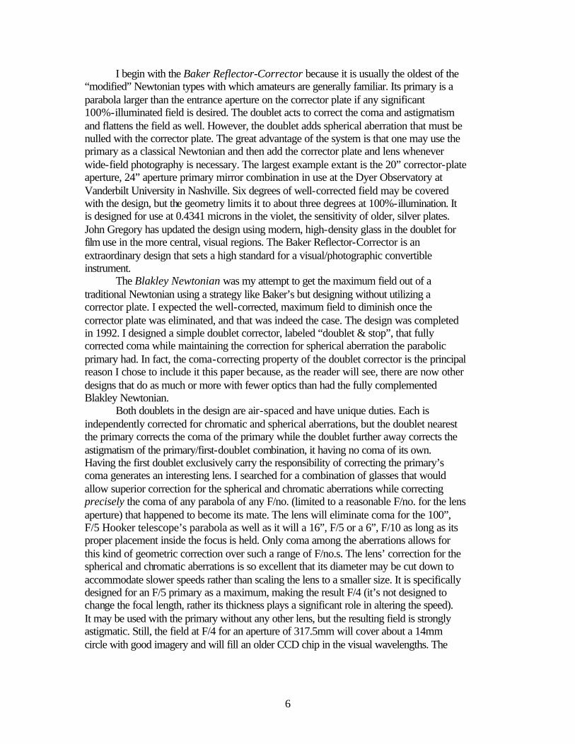
diffraction-limited, visual field, restricted by astigmatism, is about 1/8 degree at F/4 compared to 1/20 degree for the naked parabola limited by coma at the same speed. The purpose of the second doublet is to correct the astigmatism generated by the first doublet and the parabola. Unlike the coma-correcting doublet, this doublet must be specifically designed for each telescope that will utilize it. The resulting field is curved but is fully corrected for astigmatism. The diffraction-limited visual field is ¼ degree at F/4.9. Peter John Smith has designed a system that is superficially like the Blakley Newtonian. His design utilizes a hyperbolic primary and the set of doublets have a distribution of aberration correction that is different from my choice (ref. his site at www.users.bigpond.com/PJIFL/ and scroll down to the telescope designs). For visual use, the field curvature of the Blakley Newtonian at radius 500mm (somewhat shorter than for wide-field use) concave to the eye actually benefits the eyepiece, but for the maximum of wide field use with film or CCD, a field flattener is added near the focus. Fig. 3 provides graphs showing the extent of the astigmatism for the three variants of the Blakley Newtonian just described. The last lens in the system falls to the right of the Y-axis located at the focus in each plot. The Y-axis units indicate angle from the field center for the chosen field. The X-axis is the optical axis. The sagittal “S” and the tangential “T” curves are labeled. The field curvature’s arc falls between the S and T curves but isn’t shown. The plots were generated with ZEMAX software. Here one can see immediately how the astigmatic curves are manipulated with the addition of properly designed lenses in the optical train. Fig. 4 presents Blakley-Newtonian spot diagrams for the two, four, and five lens configurations for “CCD”, “Photo” (also good for CCD unless a “curved field” or “field radius” is specified under the title; film can be curved to fit), and “Visual” use. The spots were generated, as have all spots in this paper, with ATMOS software provided by Massimo Riccardi (ref. web.tiscali.it/ATMOS/ for the designer’s software site). The spots were plotted for field center and percentage locations to the design field edge. The half field is listed under the right-most spot. At the left may be a 0.025mm circle that is considered the encircling standard for photographic and CCD use (three, aligned, 9 micron pixel squares exceed its diameter a bit). All “Visual” plots are encircled with a circle the size of the Airy disk. The colors represent the various wavelengths as follows: dark red: 0.7065 microns, red: 0.6563, green: 0.5461, and blue: 0.4861. The “Visual” spots eliminate the dark red: 0.7065 microns. In the first set of plots following, the best-focus position for a flat CCD or film plane was chosen within the curves shown in the left-most plot of Fig. 3.
8
Blakley Newt., F/4.04 Blakley Newt., F/4.87 Blakley Newt., F/4.87 2-element corrector curved field, 4 elements flat field, 5 elements
Astigmatism
Fig. 3
Here are some final notes on the Blakley Newtonian. Faced with “competition” of higher efficiency, the one redeeming trait the design has over the others is that it can be used with a two, four, or five lens combination giving full coma and spherical aberration correction in each case. The first doublet, the coma corrector, has some short radii that would likely be critical as perhaps are the elements’ thicknesses. It carries the system stop primarily because its geometry limits its size (its %-obstruction is the lowest among the designs offered) and some improvement in aberration results at fast speeds, but a slightly slower system won’t be troubled with having the stop located on the primary. The coma corrector also carries the advantage that it may be transferred for use to any parabola of any speed to a limit of about F/5 (of course, it must always be properly located from the focus). It may also be used in a reduced-aperture version without scaling, and this certainly favors the designer. I anticipated that the Newtonian diagonal would locate just after this doublet. The second doublet must be designed for the specific telescope, and I arbitrarily chose to space it so that it could be mounted in the end of the telescope’s eyepiece adapter or even the drawtube. Perhaps when designed for a new location, maybe with different glasses, one could eliminate the fifth lens required for field flattening. Peter J. Smith’s work suggests this.

9
0.025mm Circle Center Field 70% Field 100% Field (0.32°)
CCD: Blakley Newtonian with 2-element coma-corrector; F/4.02
0.025mm Circle Center Field 70% Field 100% Field (0.8°)
Photo: Blakley Newtonian with 4-element corrector; F/4.91
(Spots plotted on curved field with radius of –600mm.)
0.025mm Circle Center Field 70% Field 100% Field (0.8°)
Photo: Blakley Newtonian with 5-element corrector; F/4.87
Center Field 70% Field 100% Field (0.125°)
Visual: Blakley Newtonian with 4-element corrector; F/4.91 (Each spot shown imposed on Airy-disk circle
& plotted on a field radius of –500mm.)
Fig. 4
10
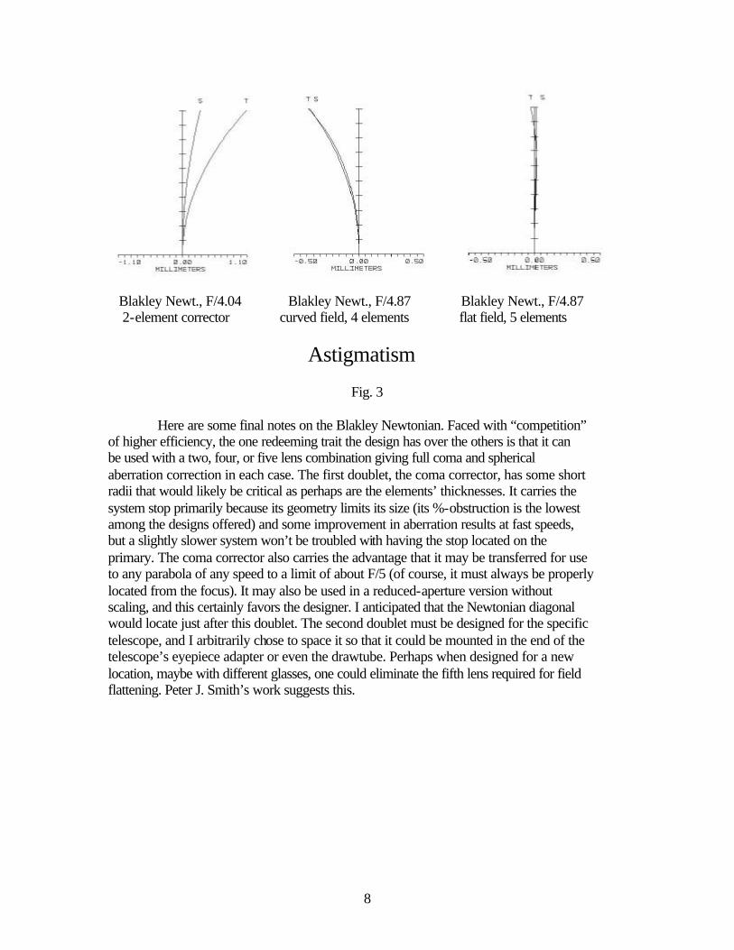
The Wynne Newtonian design was produced and contributed by Massimo Riccardi. The Wynne triplet has long been used with Cassegrain and Ritchey-Chretien designs but the amateur community has perhaps been unaware that it can be used with Newtonians as well. There aren’t many “professional” Newtonians because of the difficulties of mounting heavy instruments on a Newtonian focus, so Wynne triplets weren’t generally designed for Newtonians. (Richard Berry informed me at the ALCON 2002 meeting, however, that the University of Texas now operates a Newtonian of about one meter aperture with a Wynne corrector.) We may reference the spot diagrams for the system in Fig. 5. Notice how beautifully concentrated the spots are even at 1.3 degrees off axis for the “Photo”/CCD system! The wavelengths covered are colored as before with 0.7065, 0.6563, 0.5461, 0.4861, and 0.4583 (violet) as new. The 100%-illuminated field of 2.6 degrees may be extended to a value 50% greater with refocusing! Riccardi has designed faster systems also with incredible fields. The fields become so large as to make the obstruction caused by the triplet grow so that the primary mirror is severely obscured from incident light! Notice the concentration of the spots within the Airy disk for the “visual” system for 0.6563, 0.5461, and 0.4861 microns. The full, diffraction-limited field is one degree!
- 0.025mm Circle Center Field 70% Field 100% Field (1.3°)
Photo: Wynne Newtonian; F/4.41 (modified by Blakley, designed by Riccardi)
Center Field 70% Field 100% Field (0.5°)
Visual: Wynne Newtonian; F/4.41 (Each spot shown imposed on Airy-disk circle.)
Fig. 5
My contribution in this design comes in increasing the field slightly with a change of glass in the third element, the result as is shown here. P.J. Smith has also designed a Wynne Newtonian that utilizes some commercial lenses (on his web site).
11
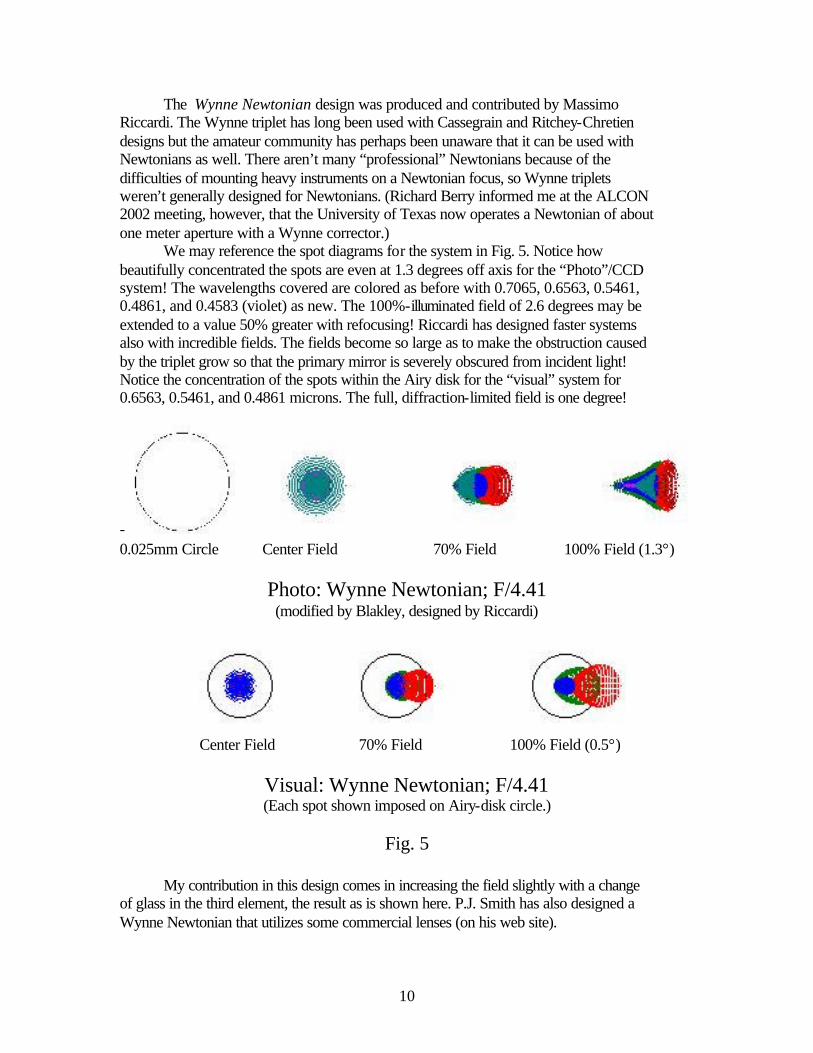
Massimo Riccardi cautions that the manufacturing, centering, spacing, and mounting tolerances of the lenses for a Wynne triplet are tight. One should consider this, but this is a situation that is probably true for all of the designs presented in this paper. The next design, by Klaas Honders, is probably the most extraordinary of any in this paper (I am thankful to Mr. Bratislav Curcic who alerted me to Honders’ effort). Massimo Riccardi modified it slightly to improve its performance over a wider field and also designed F/3.67 and F/2.67 versions. E. Wiedemann published his folded version of F/1.25 in 1978 in Sterne und Weltraum (issue 8) and may (?) actually have priority.
0.025mm Circle Center Field 70% Field 100% Field (1.7°)
Photo: Honders Anastigmat; F/4.5
(modified by Riccardi)
Center Field 70% Field 100% Field (1.5°)
Visual: Honders Anastigmat; F/4.5 (Each spot shown imposed on Airy-disk circle.)
Fig. 6
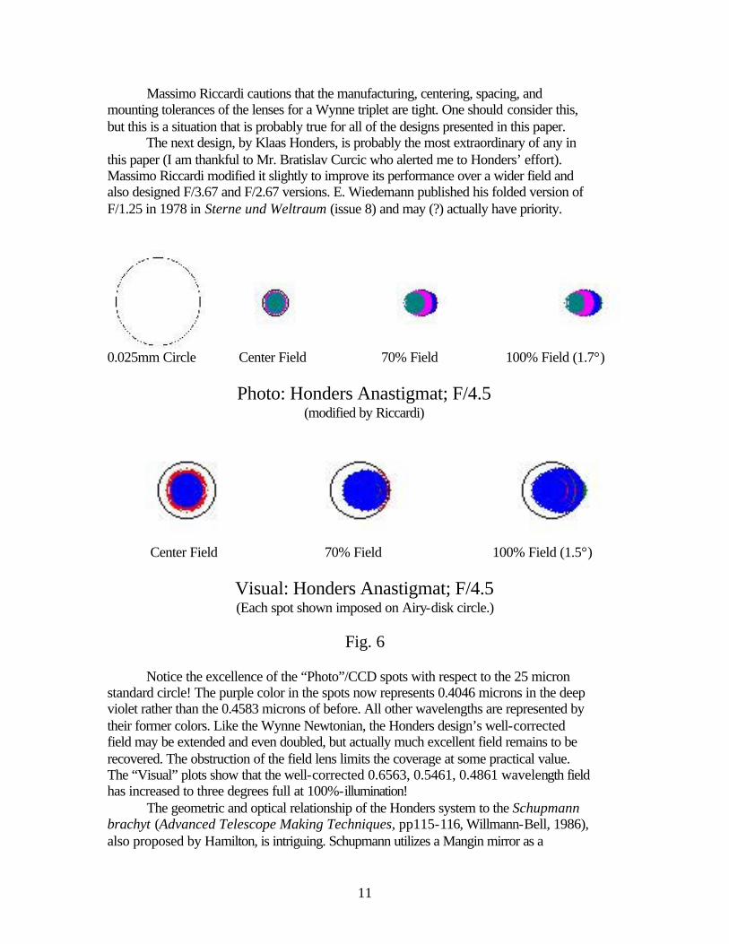
Notice the excellence of the “Photo”/CCD spots with respect to the 25 micron standard circle! The purple color in the spots now represents 0.4046 microns in the deep violet rather than the 0.4583 microns of before. All other wavelengths are represented by their former colors. Like the Wynne Newtonian, the Honders design’s well-corrected field may be extended and even doubled, but actually much excellent field remains to be recovered. The obstruction of the field lens limits the coverage at some practical value. The “Visual” plots show that the well-corrected 0.6563, 0.5461, 0.4861 wavelength field has increased to three degrees full at 100%-illumination! The geometric and optical relationship of the Honders system to the Schupmann brachyt (Advanced Telescope Making Techniques, pp115-116, Willmann-Bell, 1986), also proposed by Hamilton, is intriguing. Schupmann utilizes a Mangin mirror as a
12
compensating element for correcting the aberrations, principally chromatism, of the objective, which carries the real, focusing power in the system. Honders and Wiedemann diminished the power of the objective, placing most of the power in the Mangin mirror. In this way, the former objective becomes a sort of corrector for the Mangin. Still, lateral color (an aberration that turns stars in the field into streaks of spectra, an aberration of huge magnitude in the brachyt!) in these designs isn’t corrected unless a positive element, a field lens, is inserted near focus. I adopted a similar strategy for improving the Schupmann brachyt in 1984 by designing a compensating, Huygens eyepiece for correcting lateral color. The idea worked, but I hadn’t the experience at that time to see the significance for trying the same thing with a field lens. The tolerances for the elements in the Honders design can be severe. Two elements are known to possess exceptionally tight tolerances, the Mangin mirror and the field lens. Any Mangin mirror requires strong adherence to the design radius and smoothness criteria on the mirrored surface. Since the light rays that enter the lens surface must encounter and leave the mirrored surface at the proper location and angle, the lens surface and the element’s thickness are critical as well! Because the field lens has the responsibility of correcting the lateral color of the rest of the system, its tolerance on centering with respect to the system’s optical axis is severe as reported by Riccardi, so much so that manufacturing under such a constraint may become questionable. He reports the slightest, expected deviation from center produces intolerable aberrations! This lens also has criticalities with respect to its design radii and thickness. Add to this the problem of maintaining uniformity and dispersion consistency in the glasses (the same “melt” should be used for all elements) and the design shows there is a penalty for succumbing to its seduction!
Fig. 7
The last design that I will discuss is a development of the Honders design (I was unable to bring it up at the ALCON 2002 meeting). Again, I chose to attempt the elimination of a full aperture element, in this case, the “objective”, while retaining the Mangin for its unusual properties. I expected the field to diminish, and it has dropped to 1.6 degrees as can be seen in Fig. 7. The Blakley Anastigmat requires a doublet in place of the field lens used in the Honders to achieve about the same level of correction for chromatic aberration and lateral color. One of the glasses is a flourite-similar glass. The manufacturing issues regarding the Mangin are the same as in the Honders. I haven’t
13
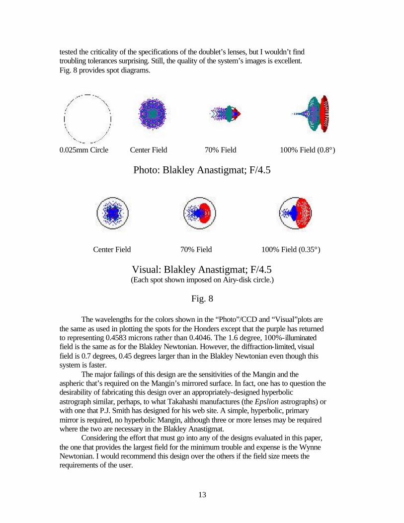
tested the criticality of the specifications of the doublet’s lenses, but I wouldn’t find troubling tolerances surprising. Still, the quality of the system’s images is excellent. Fig. 8 provides spot diagrams.
0.025mm Circle Center Field 70% Field 100% Field (0.8°)
Photo: Blakley Anastigmat; F/4.5
Center Field 70% Field 100% Field (0.35°)
Visual: Blakley Anastigmat; F/4.5 (Each spot shown imposed on Airy-disk circle.)
Fig. 8
The wavelengths for the colors shown in the “Photo”/CCD and “Visual”plots are the same as used in plotting the spots for the Honders except that the purple has returned to representing 0.4583 microns rather than 0.4046. The 1.6 degree, 100%-illuminated field is the same as for the Blakley Newtonian. However, the diffraction-limited, visual field is 0.7 degrees, 0.45 degrees larger than in the Blakley Newtonian even though this system is faster. The major failings of this design are the sensitivities of the Mangin and the aspheric that’s required on the Mangin’s mirrored surface. In fact, one has to question the desirability of fabricating this design over an appropriately-designed hyperbolic astrograph similar, perhaps, to what Takahashi manufactures (the Epslion astrographs) or with one that P.J. Smith has designed for his web site. A simple, hyperbolic, primary mirror is required, no hyperbolic Mangin, although three or more lenses may be required where the two are necessary in the Blakley Anastigmat. Considering the effort that must go into any of the designs evaluated in this paper, the one that provides the largest field for the minimum trouble and expense is the Wynne Newtonian. I would recommend this design over the others if the field size meets the requirements of the user.
14
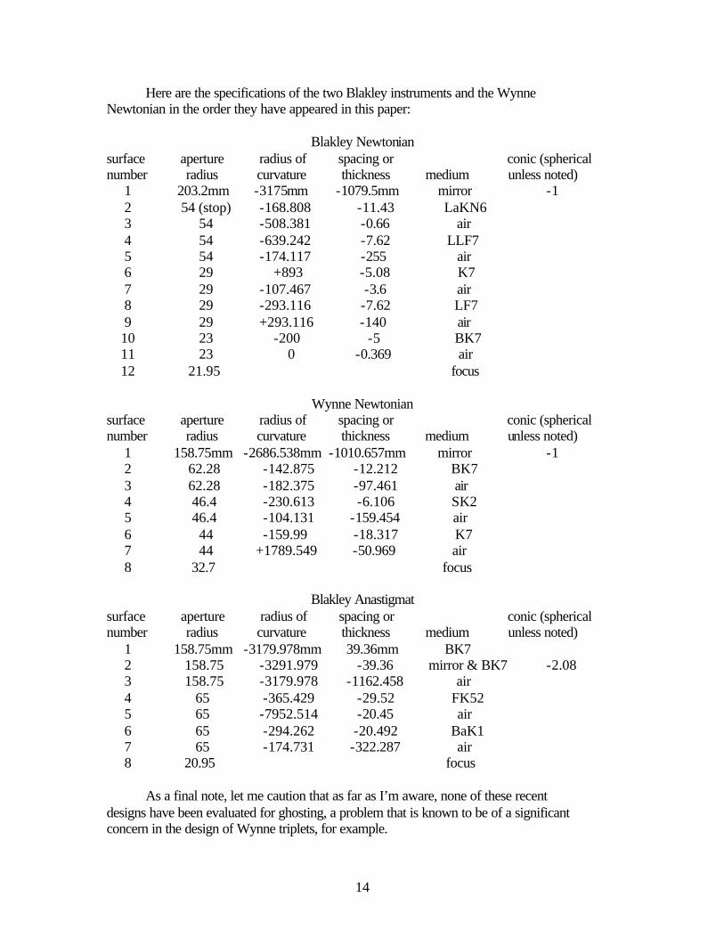
Here are the specifications of the two Blakley instruments and the Wynne Newtonian in the order they have appeared in this paper:
Blakley Newtonian surface aperture radius of spacing or conic (spherical number radius curvature thickness medium unless noted) 1 203.2mm -3175mm -1079.5mm mirror -1 2 54 (stop) -168.808 -11.43 LaKN6 3 54 -508.381 -0.66 air 4 54 -639.242 -7.62 LLF7 5 54 -174.117 -255 air 6 29 +893 -5.08 K7 7 29 -107.467 -3.6 air 8 29 -293.116 -7.62 LF7 9 29 +293.116 -140 air 10 23 -200 -5 BK7 11 23 0 -0.369 air 12 21.95 focus
Wynne Newtonian surface aperture radius of spacing or conic (spherical number radius curvature thickness medium unless noted) 1 158.75mm -2686.538mm -1010.657mm mirror -1 2 62.28 -142.875 -12.212 BK7 3 62.28 -182.375 -97.461 air 4 46.4 -230.613 -6.106 SK2 5 46.4 -104.131 -159.454 air 6 44 -159.99 -18.317 K7 7 44 +1789.549 -50.969 air 8 32.7 focus
Blakley Anastigmat
surface aperture radius of spacing or conic (spherical number radius curvature thickness medium unless noted) 1 158.75mm -3179.978mm 39.36mm BK7 2 158.75 -3291.979 -39.36 mirror & BK7 -2.08 3 158.75 -3179.978 -1162.458 air 4 65 -365.429 -29.52 FK52 5 65 -7952.514 -20.45 air 6 65 -294.262 -20.492 BaK1 7 65 -174.731 -322.287 air 8 20.95 focus As a final note, let me caution that as far as I’m aware, none of these recent designs have been evaluated for ghosting, a problem that is known to be of a significant concern in the design of Wynne triplets, for example.