ap100us 2010.02 update release - amada global version 2010.02 update & release notes ... 7025...
TRANSCRIPT

AP100US Version 2010.02
1
7025 Firestone Blvd. Buena Park, CA 90621 877-AMADA-US
For support please contact usPhone: (800) 254-7532
Email: [email protected]
AP100US Version 2010.02 Update & Release Notes
Thank you for purchasing Amada’s AP100US! These release notes outline the new features or changes in the latest version of the software as well as information regarding updating to the current version. These modifications are in response to customer feedback. The AP100US CAD/CAM System is licensed software, and cannot be freely distributed. Please read the license agreement that accompanies the software.
CONTENTS
System Requirements………………………………………………………………………………………………………………………… P2
Post-Release Enhancements – v2010.01…………………………………………………………………………………………… P3
New Features – v2010………………………………………………………………………………………………………………………… P3
New Features – v8.03………………………………………………………………………………………………………………………… P6
New Features – v8.01………………………………………………………………………………………………………………………… P6
New Features – v8.0…………………………………………………………………………………………………………………………… P7
New Features – v7.01………………………………………………………………………………………………………………………… P9
New Features – v7.0…………………………………………………………………………………………………………………………… P9
Fixed Issues - v2010.02……………………………………………………………………………………………………………………… P11
Fixed Issues - v2010.01……………………………………………………………………………………………………………………… P14
Fixed Issues - v8.03…………………………………………………………………………………………………………………………… P17
Fixed Issues - v8.02…………………………………………………………………………………………………………………………… P18
Fixed Issues - v8.01…………………………………………………………………………………………………………………………… P21
Update Installation via Download………………………………………………………………………………………………………. P25
Update Installation via Online Update……………………………………………………………………………………………….. P28
Update Installation via DVD Install……………………………………………………………………………………………………. P28
AP100US Version 2010.02
2
7025 Firestone Blvd. Buena Park, CA 90621 877-AMADA-US
For support please contact usPhone: (800) 254-7532
Email: [email protected]
Important This is a cumulative patch file for AP100US Version 2010.02 only! The patch fi xes the following problems and adds the enhancements outlined in this document. This service patch is intended for users currently running version 2010. It is not intende d to upgrade 8.x or ear lier versions. You will render your current 8.x and earlier software inoperable if you attempt to use this patch!
System Requirements Hardware Description
CPU Intel Pentium 4 1.2 GHZ, AMD DURON 1.2 GHZ or higher 32 bit CPU.
Memory 1 GB of RAM (2 GB or more recommended).
Hard Disk 1 GB of free hard disk space.
Pointing Device Mouse with wheel button.
Video Graphics card capable of supporting a minimum resolution of 1024x768. 32MB Video RAM recommended with 32-bit colors.
Protection Block You cannot install or operate the software without the protection block.
Multimedia An optional sound card.
Software Description
Operating System
Microsoft Windows 2000, 2003 Server, XP Professional 32-bit, Vista 32-& 64-bit, Windows 7, 32- & 64-bit.
Sentinel Driver You must install the Sentinel Driver before you can install the AP100US System or optional software packages. (Note: Sentinel Driver automatically installs in most setups. If it does not, please refer to the PDF manual located on the CD-ROM or within the AP100US folder on the hard disk.)
Network For a network installation, the computer server must be running the server versions of Windows 2000 or Windows 2003 Server. Also, it may be necessary to update the Sentinel Driver on the computer server.
ADDITIONAL INFORMATION
Supports SolidWorks® 2010, SolidEdge® 16, 18, 19 & ST2.
If both SolidWorks® and SolidEdge® are installed on the same system, an OLE integration conflict will occur in AP100US.

AP100US Version 2010.02
3
7025 Firestone Blvd. Buena Park, CA 90621 877-AMADA-US
For support please contact usPhone: (800) 254-7532
Email: [email protected]
IMPORTANT! Make sure to completely read and understand the installation instructions. You can render your current software unusable if you perform the installation incorrectly! Back up your current set of machine drivers to a safe location. If you encounter any problems, please contact Technical Support. You should develop an installation strategy before performing a new or upgrade installation.
Files you create i n a new version of the AP100US System are not backward co mpatible with previous versions of the software.
You can import files created in previous vers ions of the AP100US System into the latest version. However, some versions require using the Convert File Names option found on the Fi le menu to convert fi les that use the V irtual Di rectory fi le format to t he 32-bit, long f ilename format. Please see Chapter 2: Getting Started, in the AP100US System Manual.
In some cases, you will have to use the File Stuff/Backup option in a previous version of the software to convert the file names.
Post-Release Enhancements – v2010.01
1. Machine Info
Previously the Machine Setup file was automatically output to the NC file folder; the user had no control over this. Now a checkbox has been added and when checked, the user can select another directory.
New Features v2010
1. Microjoint Tool Improvement
This option allows Microjoints to be automatically placed on internal cutouts. In addition, menu items have been added to allow the user to easily Assign, UnAssign, Clear and Inquire MJ Tool.
2. Pre-punch Tool Sequence Control
Pre-Punch hits have become an attribute of the cutting path, giving the user more control over Pre-Punch hits. The pre-punch tool is able to sequence inside the subroutines or macros, and the system generates the macro code for pre-punch tool hits.
3. Import Cutting Table
The Cutting Table from the machine controller has been imported into the program. A new Condition File is used to load the JKA or JKM file into the CAD/CAM system and the View Cutting Table option displays cutting table information.
AP100US Version 2010.02
4
7025 Firestone Blvd. Buena Park, CA 90621 877-AMADA-US
For support please contact usPhone: (800) 254-7532
Email: [email protected]
4. Turret Graphic Numeric Display
In order to identify the location of each station in the view, the Turret Illustration can now display the station numbers for each station. The Turret Illustration with station numbers can also be printed.
5. Output Machine Setup Improvement
The program can now output the Setup Sheet to a separate folder, giving the user full control of the setup sheet files location.
6. Tool Order in NC Code Setup
The user has the option to either output the Tool List in the setup sheet in the order that the tools were sequenced, or in the order that they appear in the turret.
7. Bump Protective Zone
A configurable border or zone can be placed around a part boundary, in order to prevent parts from overlapping during nesting. Moving and copying parts while Bump mode is enabled is still allowed.
8. Laser Cutting Path in Priority Order List
A Cutting Inside Tool and Cutting Perimeter Tool are now available in the Auto Sequence Priority tooling order for a combination machine. For laser machines these tools are called Inside Laser and Perimeter Laser.
9. Auto-Search for Optimized Cutting Sequence
Previously the snap points were used as starting point in the cutting sequence path. As a result, the sheet cutting path was not optimized. Now the system will find the closest point on the next cutting pattern instead of the closest snap point to minimize the cutting sequence.
10. Run Time Estimate
The Runtime setting feature calculates the operating time after the pattern assigned tool, enabling the user to make decisions based on the calculated runtime.
11. Easy Edit Functions
This feature makes editing patterns easier by allowing patterns in parts to be edited with simple mouse-clicks. Certain editing functions can be pre-selected and applied directly to patterns in the work area.

AP100US Version 2010.02
5
7025 Firestone Blvd. Buena Park, CA 90621 877-AMADA-US
For support please contact usPhone: (800) 254-7532
Email: [email protected]
12. Update Modified Parts
If a part is modified, this feature will automatically compare geometry and tool assignment, and prompt the user that the part was changed after the sheet was created. Changes are viewable in the part preview.
13. Sheet Wizard
The Sheet Wizard now supports multiple sheet generation. The Nested Layout logic is improved and the module can now display NC code in the Results Page. Sheet Wizard also has an improved interface that simplifies setting up a new sheet.
14. Shape Library
The Shape Library allows the creation of a User-Defined Shape Library, allowing the user to conveniently select, modify and place standard shapes onto a part or sheet.
15. Add Die Clearance
This new feature has the ability to batch add Die Clearances to the tool inventory during Setup.
16. Tool Comment Information
A new column is added to the Tool Inventory window and the NC Sequence Viewer, which displays user-entered Tool Comment information.
17. Material Setup
A Material Setup dialog box has been added to the installation procedure, allowing the user to load preset Material Files for different machines.
18. Change Line Side - Scribe Path
The user can change the punch line side for a single pattern, or for an entire scribe path. Individual line segments can be assigned different scribe tools, and different punch line sides.
19. Improve Laser Material Name
The CAD/CAM system will search the Laser Material Name in the JKA file based on the Material Type and Thickness.

AP100US Version 2010.02
6
7025 Firestone Blvd. Buena Park, CA 90621 877-AMADA-US
For support please contact usPhone: (800) 254-7532
Email: [email protected]
20. Cutting Sequence Direction Arrows
Now the user can select the type and quantity of arrows that illustrate the cutting sequence direction.
21. New Bend Parameters Options
New CAD/CAM options allow the user to select bending and V Width options. These selections automatically produce a Bend Deduction value, which is editable by the user.
New Features - v8.03 The Sy2 file can now be saved into the SDDJ in the same way as the NC file is.
In addition to TK and Part Remover (PR) Unloading, the system now supports PR-C1 Unloading.
New Features - v8.01
The tool shape in the turret is now easier to identify. Selected tooling is highlighted to make them more accessible to the user.
Tools redraws will no longer slow down or disrupt Zoom and View Sequence changes, even when a large number of tools are placed and sequenced in the work area.
Amada TK & and Amada PR loaders now have default configuration values in the software, to simplify operation. Discover Dead Zone control, Tab Punchouts for improved sheet unloading, effective Auto Final Hit programming and Last Hit speed control for your PRII.
Output compatible .PRT files for FabriVISION systems. Now you can export native files for the FabriVISION machine.
Bending values previously had to be redefined each time they were used. Now, the most recent values are loaded by default in the Bend Parameters.
A “Title Display” button appears in the “Color and Style Parameters” tab within Preferences, allowing the user to control the title bar display in the AP100US CAD/CAM system frame window. With this button, the user may enable/disable file name display respectively. Also, the user is able to adjust the display order in title bar.
The Select Material File dialog box is now resizable and will keep the window size saved. A new Horizontal scroll toolbar is added into the dialog to help read items listed.
AP100US Version 2010.02
7
7025 Firestone Blvd. Buena Park, CA 90621 877-AMADA-US
For support please contact usPhone: (800) 254-7532
Email: [email protected]
New Features - v8.0 Part Edge in common with Sheet Edge
If the part edges and sheet edges coincides, the overlapped edges will not be sequenced. This new feature applies only to the punching machines when the "No Grid Parts" option has been enabled.
If part(s) are modified after the sheet had been generated, the AP100US CAD/CAM system will display a message and list out the changed part(s). The modified parts can be distinguished easily this way.
The AP100US CAD/CAM system can now load the SolidWorks® 3D parts directly without opening SolidWorks®. 3D part loaded in is unfolded automatically.
The AP100US CAD/CAM system now passes the cutting side flag to the driver, so the driver can tell if the cutting is inside, outside or on the pattern.
Network license runs on Windows Vista now, the user can set Network license for their CAD\CAM system which running on the new Vista platform.
New Undo/Redo menu added, which supports the undo/redo operations of Draw, Tool, and Sheet. Multiple steps of undo/redo are supported.
When designing a special tool, they keyed angle marker and special tool dead zone are now displayed so the user can easily determine their location during the design process, tell where the key angle is, and what the dead zone is.
Nesting data can be customized and exported to an Excel file, for integration into other applications.
Users can now set a gap value for the scribe tool. The gaps of the tool hits on different patterns are now uniform. The User can box select (or “fence select”) the patterns to be scribed.
Micro Joint tools now support common angle when sequencing.
The “Walk Thru Wizard” is now called “Sheet Wizard.” Sheet Wizard automatically checks micro joints, missing tool assignment, tool interferences, etc, and prompts the user to intervene. After reviewing the sheet, simply click save and return to the wizard to continue. As an option, generated NC code and sheets can be saved, and the sheet report can be viewed at the last step.

AP100US Version 2010.02
8
7025 Firestone Blvd. Buena Park, CA 90621 877-AMADA-US
For support please contact usPhone: (800) 254-7532
Email: [email protected]
Form shapes can be detected, if they exist on the face of a SolidWorks® 3D model. The user can map the special shape with the special tool in AP100US. After OLE import, form features of SolidWorks® become a group in AP100US and special tools can be assigned for the groups.
Support drivers generate the SY2 file, and each machine can have it’s own SY2 file format, easily customized for individual machines.
The user can now view the sheet information easily, using the Sheet Information window. Both Material Settings and CAM information are contained in the “Sheet Information” window. The user can input comments and specify a customer as well, to include with the sheet data.
The First Travel Range is for the user to specify and control the processing range of the reposition, so the sheet won’t become weak and the clamps can hold the sheet tightly when repositioning.
To have the AP100US CAD/CAM system integrated with FMS, certain files with defined formats can be created.
The Tool Preview has been moved from the output area and floating on the work area. Keyed angles display in the preview also.
Common cutting happens when the distance of the parts’ boundary equals to beam width. This applies to non-similar parts, too, not necessarily the same part.
Letters can be designated for station sizes freely, not just in an alphanumeric order. Letters can be swapped also. The letters which are occupied display in the red color.
The Part Info windows are now unified into one single window. The window is standard for all users, regardless of modules or packages used with the AP100US CAD/CAM system- there is no difference for IntelliNEST vs. Non-IntelliNEST users.
AP100US Version 2010.02
9
7025 Firestone Blvd. Buena Park, CA 90621 877-AMADA-US
For support please contact usPhone: (800) 254-7532
Email: [email protected]
New Features - v7.01 The system will get the Customer Data as well as Revision Data output from Part Info,
and output it to the NC Code.
All sheets can have the remnant cut now, after nesting.
Now shows tools with angle as a setting in the turret, regardless if the setting in Tool menu is “From Turret” or “From Tool Inventory”.
The system will retain more tools when changing the machine file.
The maximum (“max”) microjoint that can be added in the system is now expanded to 250.
New Features - v7.0 The Part Information window contains much more information than ever before. The
part information is divided into two categories, i.e. generic and specific information. The generic information contains CAD Information, CAM Information and Production Information. The specific information contains Nesting Information.
The system can display the overtravel not only for the cutting machine, but also for the punching and combination machine. If you use the punching machine to process the sheet, the system can display the travel zones for the tools. If you use the combination machine, the system can display the cutting travel zone and punching travel zone for the Pre-Punch.
This function provides the user with easier and more intelligent tool assignment. The system will list all the matching tools for the pattern you select from the drop-down list automatically.
Many notch templates are available in the system. The user can select one template and set it as needed, which makes creating notches easier and quicker. You can assign a relief tool to process the notch holes.
This function allows you to add a flag on the pattern, indicating the tool on the pattern is fixed or the pattern can’t be assigned a tool when you load the part or machine.
This function provides you with a quick method to get all functions done by a few clicks of the mouse. This reduces too much work for the system settings and raises the production efficiency greatly.
This is an extended function in the nesting. The system can remove, sort and stack the machined parts from the machine. The position of last hit is determined by the system automatically.

AP100US Version 2010.02
10
7025 Firestone Blvd. Buena Park, CA 90621 877-AMADA-US
For support please contact usPhone: (800) 254-7532
Email: [email protected]
The MJC is short for Micro Joint Cutter, which cuts the joint part in the unloaded sheet with joint. The IJP is short for Ink Jet Printer, which has a function to print part name, part size and other information on the part. There are two types of IJP device. One is combined with the MJC device, and the other is individual.
Duct Unfold creates unfolded parts of an air-duct. The User selects an air-duct shape from the list and enters the parameters of the shape, such as height, width, diameter or angle. The system calculates the unfolded shapes and transfers them into AP100US.
The Cross-Section Unfold creates unfolded parts by rough sketched cross-section figures. The User roughly draws cross-sections and defines the parameters such as length, angle or bend allowance. The system calculates the unfolded shapes and transfers them into AP100US.
The Flange Unfold creates unfolded parts by adding some flanges on a specified base face. User draws a base face shape in AP100US, and then launches Flange Unfold. The Flange Unfold receives the base face shape and the user specifies some parametric flange shapes on it. The flange shapes are drawn by the same way as cross-section unfolding. User also can break the part by 3D edit functions if needed. The system calculates the unfolded shapes and transfers them into AP100US.
The Simulation module is software for validating NC programs created on AP100US. If you perform simulation before proceeding with an actual process, you can predict the time of each process, discover probable errors, and avoid any mishaps. This software also enables you to edit or create new NC programs.
The system imports the bending properties including the bend line length, the bend angle, the inner radius, the bend deduction, the bend direction and the bend order.
This function allows the Part Number, Programmer Name and Comments in the Part Information window to be output in the NC Code files.
This function allows you to control faces and also angles when OLE from SolidWorks®.
This function will help the new user to setup some necessary files conveniently, such as tool inventory, material files, material inventory etc. Then user can run and use the system to design and generate NC code after he installs the system for the first time.

AP100US Version 2010.02
11
7025 Firestone Blvd. Buena Park, CA 90621 877-AMADA-US
For support please contact usPhone: (800) 254-7532
Email: [email protected]
FIXED ISSUES - v2010.02
Cutting Sequence
1. Box and Fence Group Edit can't edit the properties correctly. This problem has been fixed.
2. Auto sequencing locks up when using the common cut process. This has been corrected.
3. After cutting the radius, the laser cuts a chamfer which it is not supposed to. This incorrect behavior has been fixed.
Easy Edit
1. Easy Edit cancels the repeated Copy or Move when snapped to another pattern. This problem has been fixed.
Edit
1. Dynamic Origin doesn’t function in Copy Patterns. Dynamic Origin now functions correctly.
2. The Origin offset Hot Key does not function. The Hot Key now functions correctly.
3. The ability to blend to lines (with the “blend pattern” function) with a radius of “0.000” to create sharp corners has been added.
Feature Tree
1. When scaling a macro the tool is lost, but the tool info still shows in the Feature tree. The tool info no longer displays.
Installation
1. Place the CADCAM Install Guide in pdf into the route of the directory of the CD. The Install Guide has been included.
2. Place the Converter after the Supplemental Disc during installation. The Converter has been included.
NC Code Generation
1. The Gcode Nesting Module passes an MJ tool, even if it is not used on the sheet. This incorrect behavior has been fixed.
2. Using the NC "Sequence Order" option causes tool setup data to be lost. This has been corrected and setup data is no longer lost.

AP100US Version 2010.02
12
7025 Firestone Blvd. Buena Park, CA 90621 877-AMADA-US
For support please contact usPhone: (800) 254-7532
Email: [email protected]
OLE Integration
1. Bend line info is lost when files from Autodesk Inventor are imported through OLE integration. Bend line information is preserved when importing files from Autodesk.
Part Info
1. Arcs and circles are not calculated in the Cut Length in the part info. This incorrect behavior has been fixed.
Punch Sequence
1. Some grid patterns have a double hits problem. This problem has been fixed.
2. When resetting the sequence and then auto sequencing again, the application crashes. This incorrect behavior has been fixed and the application no longer crashes.
3. Finn power setup sheet shows 32 extra pre-punch hits. These extra hits no longer display.
Run Time
1. A prompt should be added, so the user knows there is a delay in calculating the RunTime. This prompt has been added.
Shape Library
1. In the Design SP tool window, placing an SP instance causes a crash. The program no longer crashes.
2. The SP instance tool in the Shape Library will be replaced when loading another tool inventory. This has been fixed and the instance tool remains the same.
Sheet
1. When gridding grouped parts, and then changing the location of the grid, only the selected part is moved. This incorrect behavior has been fixed.
Sheet/Part Association
1. Part/Sheet Association does not refresh the display window after loading a sheet. This incorrect behavior has been fixed.

AP100US Version 2010.02
13
7025 Firestone Blvd. Buena Park, CA 90621 877-AMADA-US
For support please contact usPhone: (800) 254-7532
Email: [email protected]
Sheet Wizard
1. The error boundary part is highlighted in the first page, but only one is highlighted in the second page. Now error boundaries are highlighted in the second page.
Special Tool
1. The Special Tool name changes in the title bar after selecting another tool. Fixed issue.
Tool
1. When using the clear tabs option when tools have been assigned to the perimeter with the Nibble OFF, the tools will revert back to having the nibble on (H7 SheetMetal Solutions, Inc.).
Tool Assignment
1. FabriWIN incorrectly calculates the pitch when changing from .086 and .087 Materials. The pitch is now correctly calculated.
Turret Info
1. The opening parenthesis is missing when assigning a tool to the turret. The opening parenthesis has been included.
2. The Y Offset To Hold Down value can't be set in Machine>Turret>Station Info. This value can now be set.
AP100US Version 2010.02
14
7025 Firestone Blvd. Buena Park, CA 90621 877-AMADA-US
For support please contact usPhone: (800) 254-7532
Email: [email protected]
FIXED ISSUES - v2010.01 Bump Check
1. When the user bumped the selected part into a stationary part and then left-clicked, the system selected a completely different part instead. This incorrect behavior has been fixed.
2. When a part is being moved, ghost-images of that part appear on the screen. The ghost-images no longer appear in the display.
Display
1. In the tab corner with Cutting Direction Display turned on, the arrows get cut off in the display. The arrows now display correctly.
BendCAM
1. DDE Bend data (Vwidth and Bend Type data) passed to BendCAM was inaccurate. This problem has been corrected and now the valid values are passed.
File
1. When using F10 Quick Save and the “Y” key once to save, the user must select it twice. The problem has been fixed.
Import Cutting Table
1. The Material Name M102 of the current material file was not entered in the Laser Material Name field in Sheet info and the database. The Material Name now displays.
2. A new sheet with the same material set in preferences didn’t select the material name in JKA. This has been fixed.
Intellinest
1. NewAssembly2 only shows for an assembly file; if more parts are loaded and saved, the assembly will get an error. This has been fixed.
Material Info
1. When reloading a new driver, values for all conditions were set to "0", even though the user had made no changes. The system now retains the previously entered values.

AP100US Version 2010.02
15
7025 Firestone Blvd. Buena Park, CA 90621 877-AMADA-US
For support please contact usPhone: (800) 254-7532
Email: [email protected]
Microjoint Tool
1. The system gave an Error alarm when the user tried to remove the MJ sequence. Now no error appears when the MJ sequence is removed.
NC Code Generation
1. In the Microjoint tool sequence with AmNEST enabled, the values given for the MJ tool origin in the NC code pane were incorrect. Now the correct tool origin values appear.
2. The parameter is incorrect when setting up Use Part/Sheet Info =1 and generating the NC code. The problem has been fixed
Punch Sequence
1. Using the Insert Sequence function pushed the inserted sequence to the end of the code. This behavior has been eliminated.
Run Time
1. When reloading material the runtime module should calculate the time based on the feedrate and/or other related values set in the CNC Table.
2. The Output machine setup will show ESTIMATED TIME= RUN TIME instead of 00:00:00. This has been fixed.
Sheet
1. When the user selected Sheet>Move/Copy using keyboard commands, the cursor would jump to the comment line and the function didn’t work. This behavior has been eliminated.
2. Select a part, snap to the corner of the part and then type .75s to step move it and it will fail. Fixed issue.
3. The part will snap to a clamp or sheet pattern after a move to the right of sheet. Fixed issue.
4. Open the Properties dialog, and it fails to show the location of the selected, copied or active part. Fixed issue.
AP100US Version 2010.02
16
7025 Firestone Blvd. Buena Park, CA 90621 877-AMADA-US
For support please contact usPhone: (800) 254-7532
Email: [email protected]
Sheet Wizard
1. Sheet Wizard only checked if a part had microjoints and showed an alarm if they were absent. Tabs were not checked. Sheet Wizard will now check both MJ and Tabs, only giving an alarm when the part has neither.
2. Common punch should not be active between different parts in Sheet Wizard. This has been addressed.
Tool
1. The tool in the turret display showed an incorrect angle. The tool now shows the correct angle as entered in the Station dialog.
2. A large tool could be placed in a station reserved as a Multi-Tool station. This incorrect behavior has been eliminated.
Turret Station
1. In Multi-tool stations, station numbers didn’t display correctly. Station numbers now appear in the correct places.
Other
1. The system did not output the correct time in the Runtime Details dialog. A variable flag is now passed from the driver, allowing the XML format to support this type of code.
2. When Logitech® SetPoint is installed, the user couldn’t launch FabriWIN 2010.0. This has been fixed and the CADCAM program now opens normally.
3. “Inquire MJ Tool” has been removed from the Classic Menus and Customize Tool Bar Commands.

AP100US Version 2010.02
17
7025 Firestone Blvd. Buena Park, CA 90621 877-AMADA-US
For support please contact usPhone: (800) 254-7532
Email: [email protected]
FIXED ISSUES - v8.03
Cutting Feature
1. Parts in the sheet now run the Corner Radius feature without difficulty.
Draw
1. Previously, in Windows Vista repeating text in the Output box caused an “=” sign to appear. This has been corrected.
Intellinest
1. The preferred machine from the Part Info dialog box now copies correctly into the Nesting Info dialog.
Punching Sequence
1. The Microjoint Tool Sequence used in a keyed station can now be removed.
2. When using the group command for the 2" squares of the part, out of range alarms do not occur.
3. When the "Cut Entire Sheet Twice” checkbox is checked, the program no longer punches the regular punch hits twice.
Reposition
1. The Reprogrammable Clamps origin is now correct after reposition.
Sheet
1. “New Sheet” now brings in the Material Info\ Pierce Location\ Cutter Comp\ Beam Diameter value.
2. When "Clear Database for New Sheet“ is unchecked, the Machine File and Material File are disabled.
AP100US Version 2010.02
18
7025 Firestone Blvd. Buena Park, CA 90621 877-AMADA-US
For support please contact usPhone: (800) 254-7532
Email: [email protected]
3. The Tool Line Nibble command now makes the correct sheet utilization.
Tool
1. When opening a previously saved sheet, the "Tool Not Found in Inventory" error window does not display.
View
1. Mirroring parts on a sheet does not drop the Microjoints when switching from Part to Sheet View.
FIXED ISSUES - v8.02
Cutting Feature
1. The Check Attributes feature now works correctly, and will give a proper message when lead-in/lead-out and cutting features collide with parts or geometry.
Cutting Sequence
1. Cutting Sequence, which was not optimized has now been fixed.
Installation
1. When installing an upgrade, the wrong default folders from previously installed versions
would appear at times. This has been fixed in the current version.

AP100US Version 2010.02
19
7025 Firestone Blvd. Buena Park, CA 90621 877-AMADA-US
For support please contact usPhone: (800) 254-7532
Email: [email protected]
IntelliNest
1. When Common Cutting is disabled in Machine>Edit Material>Process Type by selecting
None, the beam diameter value in Common Cutting will be taken into account in the
distance between parts.
2. The “Include Leads/Features” setting in nesting now works smoothly with the Center
Rectangle option.
3. AP100US no longer pulls the micro joint length when Include Features is disabled.
Load File
1. Multiple .dxf files can be dragged into AP100US simultaneously, and the program will
still function normally. Previously the system would crash.
2. A .dxf file can be saved into AP100US without crashing the system.
3. Now PolyLines will group to a standard pattern when opening .dxf or .dwg files.
Material
1. The settings entered in Edit Material now remain when another tab is selected and
before OK is clicked. Previously these settings would disappear if OK was not clicked.
NC Code Generation
1. When NC Code is generated without an extension, no extra dot appears behind the NC
name.
OLE Integration
1. Lofted bends in SolidWorks OLE now works correctly.
2. When SolidWorks is uninstalled, and then installed in another directory, Open&OLE will
continue to work properly. Previously this action disabled Open&OLE.
3. A single SLDPRT file using a v1.0.06 Transfaddin.dll now works in the current verison.

AP100US Version 2010.02
20
7025 Firestone Blvd. Buena Park, CA 90621 877-AMADA-US
For support please contact usPhone: (800) 254-7532
Email: [email protected]
Other
1. Clamp Dead Zones are now correctly placed when the machine’s origin is in the upper
left corner.
2. The user can now run AP100US with a remote login. Previously this was not possible.
3. The entire part can now be viewed in the zoom window.
4. When running the program on a Windows® Vista OS, viewing speed (0-9) now
functions normally.
5. Selecting “Process Geometry” now properly arranges the line side on the part
perimeter.
Punching Sequence
1. The radius tool will not be shown when viewing sequence.
2. The sequence will no longer stall when Microjoints and First Travel Range are removed.
3. The system will now give an error message when the pattern is out of punching range.
4. The sequence direction will remain correct when a sheet having the last AI tool is re-
sequenced.
Sheet
1. When making a new Sheet, the Clear Database was not using the default machine from
the preferences, this has been fixed.
2. The material file will change in accordance to a machine change in the New Sheet
dialog.
Template Report
1. The Bridge Microjoint Tool will show up in Template Report.
2. Bend Part Report no longer prints with a black background, and the Turret Report is not
shaded.
3. The full special tool name is now output on the template report.
AP100US Version 2010.02
21
7025 Firestone Blvd. Buena Park, CA 90621 877-AMADA-US
For support please contact usPhone: (800) 254-7532
Email: [email protected]
4. A new control in Print Setting has been added to enable zoom all or not before printing.
Tool
1. The correct keyed angle now displays in Design Special Tool. Previously the incorrect
angle displayed.
2. An SP tool assigned in Part Mode will retain its angle after the part is rotated on a
sheet.
User Interface
1. The Options Menu now turns off when the system is switched back to Modern Mode.
2. The Save As > Options button in design special tool for .dxf and .dwg is no longer
grayed out.
View
1. The gridded parts column now consistently displays on the sheet mode when Zoom in is
enabled.
FIXED ISSUES - v8.01
1. AP100US 8 .01 includes an improved prev iew system. The progr am now p roperly renders part file previews that would not display previously.
2. The t ool color f unction has been improved t o display consistently, when it prev iously would not.
3. When opening a part or zoom ing on a part, the sys tem wi ll not take the co mment dimension into account if the comment is empty.
4. Some patterns “jumped” from an original .DXF or .DWG file when the user set the unit as millimeter upon import.
5. When t he Di splay Cut ting Di rection opti on in Preferences is enabled, the cutting direction displays en when using the mouse wheel to zoom in and zoom out.
6. Change tab size in Preference could not take effect when assigning Corner Notches. 7. Previously, only one assembly would load in from the Open File menu. Now, the system
can load multiple assemblies at the same time. 8. When using "drag-and-drop“ function to open DXF file, the system previously would not
consider the dimensions of the part file. 9. Condition Ran ges f or Arcs w ere permanently ch ecked before, w ithin th e C ondition
Tables of Material Information.
AP100US Version 2010.02
22
7025 Firestone Blvd. Buena Park, CA 90621 877-AMADA-US
For support please contact usPhone: (800) 254-7532
Email: [email protected]
10. When the Zoom window wa s previously open , the s ystem woul d hang up i f the u ser shifted programs while generating NC code.
11. Open & OL E opt ion in t he F ile menu w as previously unavailable w hen Soli dWorks 2008™ was installed. This feature is now available.
12. Both Open & OL E an d OLE int egration now w orks w ith SolidWork s 2008, in Windows Vista.
13. The "Location on Sheets" and the "Sheet Layout Setting" values in the Machine Settings previously appeared be different by a factor of 25.4". This has been corrected.
14. The NC Path n ow display s correct ly. P reviously, t wo slash es (“ \\”) appeared in t he file path.
15. The Online Tutorial has been updated for the ne w version of the A P100US CAD/CAM software.
16. Sometimes the Last Tool Hi t coul d not be added correctly in a sheet using PRII. This has been fixed.
17. The last tool hit is on ly assigned to a l ine when using PRII. Previously, when using the PRII system, the last tool hits could be erroneously assigned to either a Line or an Arc.
18. The system displays the auto unloading sequence view, now. 19. New Sheet Information dialog will no longer pop up when popups are disabled. This can
be changes in Display Mode Settings, within Preferences. 20. Some special tools did not follow the Common Angle rule, previously. 21. Some peripherals including the Amada PD C machine did not follow the Common Angle
rule, previously. 22. The tool hits placed on a radius corner were missing after auto sequencing. 23. The template report now remains appropriately scaled upon launch. Previously, it would
sometimes be affected by an active current zoom scale. 24. Using the " Put In Same Stati on" option to replace a too l now works properly. An error
would occur previously and the tool could not be put into the station. 25. Smaller sized tools can be used in larger stat ions, If the user checks “Use Adapter” and
properly assigns the tool. Previously, a sm aller sized tool would become los t whe n loading the machine.
26. When the user added a special tool, the Open dialog would close after adding the tool to the inventory. Now, the dialog remains open, to permit additional loads.
27. When the user made a new sheet, the tools assigned to the station could disappear from the default machine and inventory, previously.
28. Previously, in combination machines, users could only assign " last tool h it" to finish a line. Now, "last cut" is also available.
29. If a mater ial or machine name was too long , the syste m would only show part of the name on the program title bar, previously.
30. The charac ter li mit f or the buil t-in Dyna mic Calculator has been increased to accommodate more than six characters, allowing much more complicated calculations.
31. In previous versions of AP100US, the program would end the Separate comma nd after a part was separated. Now the function remains selected and available.
32. The correct punch seq uence and cut sequence features should be available t o users within the menus. Previously, some items were not listed in the menu.
33. Parts with tabs will not list in the Parts without Microjoints column in Sheet Wizard. 34. Hole sequencing has been improved when using NC View in Sheet Wizard. 35. The system would crash after customizing toolbars by deleting icons from Standard
toolbar.
AP100US Version 2010.02
23
7025 Firestone Blvd. Buena Park, CA 90621 877-AMADA-US
For support please contact usPhone: (800) 254-7532
Email: [email protected]
36. When two punching machines were loaded one after the other, the Overtravel lines did not refresh until Machine Info was selected and closed.
37. The system should show “min dead zone” and “active station’s dead zone” when inquiring tools and viewing sequence.
38. The “convert dialog” display was too small. 39. The system would show different dimensions or parts in part mode when clicking the
different part names on the part list dialog. The part and part name on the window caption does not automatically change.
40. Close pull down menus would disrupt the display. 41. When loading DXF, IGA, DWG or IGS files, the system would ask the user to load sheet
size and material thickness. 42. DXF files loaded through the Walk-Through Wizard will have a line side problem; the
part should be processed. 43. Added a switch to turn off the pop-up message for applying material and sheet
thickness. 44. “Apply material thickness and sheet size” system message would appear when loading
old part, DXF file, DWG files, etc. 45. DXF file output from the system would mistakenly create open entities. 46. “Cancel” button missing in the New Part dialog. 47. When selecting Grid, clicking on the part and then centering Grid-X to put the part on
the center of the sheet, the system moved the part to the far right side of the sheet. 48. When start point moved to the part corner, prepunch would not move with the start
point and stay in the original place. 49. Due to an angle placement conflict, the part did not nest with the angle set in the Part
Information dialog and the parts were lost in the nesting report. 50. An error message appeared when the user attempted to complete nesting jobs. 51. When updating the sheet after nesting, the cutoff line on the sheet could not be deleted
or edited. 52. After nesting, the tools on the part would be lost and wrong tools would be assigned to
the pattern. 53. Some parameter values were multiplied 25.4 times larger when displayed in the Tool
Assignment dialog, if units converted from inches to millimeters. 54. When using a special tool as a Wheel tool, the system did not pass the correct value to
the driver. 55. The Cancel button, which showed up during generating NC code, did not do anything. 56. The decimal value could not be entered in the Pop-Up dialog when generating NC code. 57. Generating NC code off some sheets were excessively slow, and have been optimized. 58. The Overtravel display of this sheet did not refresh when performing View Sequence. 59. System would crash when set to auto sequence with cup and stack suction cups on the
PRUL machine. 60. The system could not print variables of the Tool conditions such as “Feed Rate 1-4” in
the template report.

AP100US Version 2010.02
24
7025 Firestone Blvd. Buena Park, CA 90621 877-AMADA-US
For support please contact usPhone: (800) 254-7532
Email: [email protected]
61. The table format in the Hole Chart template should be rearranged to support one hole in one line.
62. When placing tool hits and then using “Expand All Items” to select other tools to place, the tool hits placed were always the last one selected.
63. “Check for Tool Interference” could not find the tool interference in some parts. 64. Place Special Tool Hits would have ghost image problems with drawings in black
backgrounds and white patterns. 65. When turning on common tool punch, Remove DUPLICATE HITS did not remove the
Square tool double hits in this sheet. 66. Assigning a special tool to the closed line, the system could hang up. 67. When entering the string value into some items under Edit Material\CNC Code, pressing
Enter button would change the string value into float value. 68. After clicking on Edit Reposition Amount the user was able to right click and toggle
between 69. AutoCAD could not open .DXF files converted from .PRT files, using the export program
[expgr.exe]. 70. Under Windows 2000 Operation System, the part could not be seen in the
Inquire/Correct window in CAD. 71. IMPORT/EXPORT modules would not work correctly with Power User permissions set on
NTFS hard drive partitions. 72. The “Finish” button did not work under the OLE Preview dialog, when the angle was
selected. 73. There would be one additional ellipse when importing this part into the system. 74. Part name would appear when pressing F10 or "Save As" but the part name would NOT
be the file name box after OLE import 75. Using Open and OLE from the File menu, the user could not get the Preview for OLE
dialog 76. The user could not tell which part was selected under Auto Tooling Options Dialog. 77. Added a switch to the Preferences to turn off the pop-up message for applying material
and sheet thickness. 78. Unable to show all dimensions because the window was zoomed in too close. 79. When outputting BMP file, the system would crash. 80. If the angle was rotated in the Part Info dialog and the user switched the view, the part
would rotate off the sheet. 81. Area AutoGrid function had layout conflicts. 82. The pop up dialog for generating NC code would create errors for any item displayed
behind it. 83. When entering Pattern Properties and other details, values would "round up" the input
data before being saved into the database, after the user pressed OK or Tab button to accept input values.
84. Place the ULX loader and the storage table at the left side by using ULXSIDE=1. 85. The microjoints on this part would be lost when doing auto sequence.
AP100US Version 2010.02
25
7025 Firestone Blvd. Buena Park, CA 90621 877-AMADA-US
For support please contact usPhone: (800) 254-7532
Email: [email protected]
86. The system would crash when switching to view part mode by clicking Part button. 87. With “Use Subroutines and Macro On” checked, the part gird on the sheet could not
perform prepierce. 88. Changed Part Width and Part Height into Part size X and Part size Y under the dialog for
New Part and New Sheet. 89. DimZ should be changed to “other name” in the Setup Wizard. 90. After the installation, the icons on the desktop would mess up.
Update Installation via Download Updating the AP100US CAD/CAM System via http://amadasupport.com
Note: Do not unzip the service release files to your default CAD/CAM directory.
To update the AP100US CAD/CAM system using download:
1. Run Windows Explorer and navigate to the folder C: \FabriWIN\AP100US or the CAD/CAM system folder you specified when you installed it.
2. Create a temporary folder, such as “C:\Temp” and unzip AP100US2010_2010.01.exe to it.
3. Copy backup.bat in “C:\Temp\FabriWIN” to C:\AP100US\FabriWIN or the CAD/CAM system folder and run it.
4. Copy the unzipped files in “C:\temp\FabriWIN” to the CAD/CAM system main folder you previously specified. The default folder is C:\AP100US\FabriWIN.
5. If the CAD/CAM system is installed in a 32-bit machine, copy “Sldworks.dll” in “C:\Temp\FabriWIN\32-bit” to the CAD/CAM system main folder you previously specified. If the CAD/CAM system is installed in a 64-bit machine, copy “Sldworks.dll” in “C:\Temp\FabriWIN\64-bit” to the CAD/CAM system main folder you previously specified.
6. Copy the unzipped files in “C:\temp\RTFiles” to the “RTFiles” folder of the CAD/CAM system you previously specified. The default folder is C:\AP100US\FabriWIN\RTFiles.
7. Copy the unzipped files in “C:\temp\TemplateReport” to the “TemplateReport” folder of the CAD/CAM system you previously specified. The default folder is C:\AP100US\FabriWIN\ TemplateReport.
8. You have now updated your CAD/CAM system and can run it.

AP100US Version 2010.02
26
7025 Firestone Blvd. Buena Park, CA 90621 877-AMADA-US
For support please contact usPhone: (800) 254-7532
Email: [email protected]
CAD/CAM Updated File List
Name Path Edition
MSNestExpert.dll C:\AP100US\FabriWIN 0.0.1.40
cadcam.exe C:\AP100US\FabriWIN 2010.0.1.361
cadcam_res.dll C:\AP100US\FabriWIN 2010.0.1.361
TemplateReport.exe C:\AP100US\FabriWIN 1.2.23.0
backup.bat C:\AP100US\FabriWIN
AppUpdate.exe.config C:\AP100US\FabriWIN
StationDesign.dll C:\AP100US\FabriWIN 1.0.3.3
NCCodeParser.dll C:\AP100US\FabriWIN 1.0.0.2
ExpImpDxfDwg.dll C:\AP100US\FabriWIN 1.1.0.26
DxfigsWrapper.dll C:\AP100US\FabriWIN 1.1.0.23
dxfigs.dll C:\AP100US\FabriWIN 1.1.0.24
FWFileConverter.exe C:\AP100US\FabriWIN 1.1.0.3
RunTimeServer.dll C:\AP100US\FabriWIN 1.0.0.2
RunTimeInterface.dll C:\AP100US\FabriWIN 1.0.0.2
NCCodeParserHelper.dll C:\AP100US\FabriWIN
SetParms.exe C:\AP100US\FabriWIN 1.0.3.4
csh.dll C:\AP100US\FabriWIN 2.0.40.0
Sldworks.dll (64bit) C:\AP100US\FabriWIN 1.1.1.29
AP100US Version 2010.02
27
7025 Firestone Blvd. Buena Park, CA 90621 877-AMADA-US
For support please contact usPhone: (800) 254-7532
Email: [email protected]
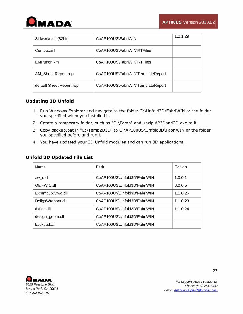
Sldworks.dll (32bit) C:\AP100US\FabriWIN 1.0.1.29
Combo.xml C:\AP100US\FabriWIN\RTFiles
EMPunch.xml C:\AP100US\FabriWIN\RTFiles
AM_Sheet Report.rep C:\AP100US\FabriWIN\TemplateReport
default Sheet Report.rep C:\AP100US\FabriWIN\TemplateReport
Updating 3D Unfold
1. Run Windows Explorer and navigate to the folder C:\Unfold3D\FabriWIN or the folder you specified when you installed it.
2. Create a temporary folder, such as "C:\Temp" and unzip AP3Dand2D.exe to it.
3. Copy backup.bat in "C:\Temp2D3D" to C:\AP100US\Unfold3D\FabriWIN or the folder you specified before and run it.
4. You have updated your 3D Unfold modules and can run 3D applications.
Unfold 3D Updated File List
Name Path Edition
zw_u.dll C:\AP100US\Unfold3D\FabriWIN 1.0.0.1
OldFWIO.dll C:\AP100US\Unfold3D\FabriWIN 3.0.0.5
ExpImpDxfDwg.dll C:\AP100US\Unfold3D\FabriWIN 1.1.0.26
DxfigsWrapper.dll C:\AP100US\Unfold3D\FabriWIN 1.1.0.23
dxfigs.dll C:\AP100US\Unfold3D\FabriWIN 1.1.0.24
design_geom.dll C:\AP100US\Unfold3D\FabriWIN
backup.bat C:\AP100US\Unfold3D\FabriWIN
AP100US Version 2010.02
28
7025 Firestone Blvd. Buena Park, CA 90621 877-AMADA-US
For support please contact usPhone: (800) 254-7532
Email: [email protected]
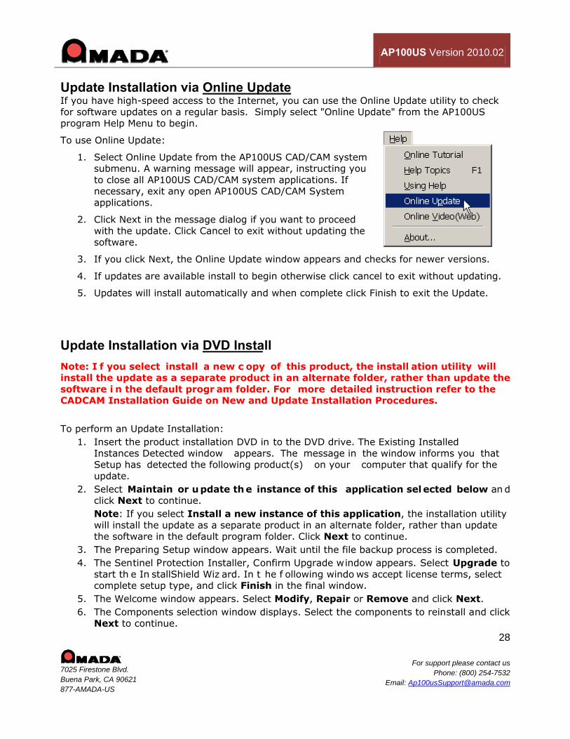
Update Installation via Online Update If you have high-speed access to the Internet, you can use the Online Update utility to check for software updates on a regular basis. Simply select "Online Update" from the AP100US program Help Menu to begin.
To use Online Update:
1. Select Online Update from the AP100US CAD/CAM system submenu. A warning message will appear, instructing you to close all AP100US CAD/CAM system applications. If necessary, exit any open AP100US CAD/CAM System applications.
2. Click Next in the message dialog if you want to proceed with the update. Click Cancel to exit without updating the software.
3. If you click Next, the Online Update window appears and checks for newer versions.
4. If updates are available install to begin otherwise click cancel to exit without updating.
5. Updates will install automatically and when complete click Finish to exit the Update.
Update Installation via DVD Install Note: I f you select install a new c opy of this product, the install ation utility will install the update as a separate product in an alternate folder, rather than update the software i n the default progr am folder. For more detailed instruction refer to the CADCAM Installation Guide on New and Update Installation Procedures.
To perform an Update Installation: 1. Insert the product installation DVD in to the DVD drive. The Existing Installed
Instances Detected window appears. The message in the window informs you that Setup has detected the following product(s) on your computer that qualify for the update.
2. Select Maintain or u pdate th e instance of this application sel ected below an d click Next to continue. Note: If you select Install a new instance of this application, the installation utility will install the update as a separate product in an alternate folder, rather than update the software in the default program folder. Click Next to continue.
3. The Preparing Setup window appears. Wait until the file backup process is completed. 4. The Sentinel Protection Installer, Confirm Upgrade window appears. Select Upgrade to
start th e In stallShield Wiz ard. In t he f ollowing windo ws accept license terms, select complete setup type, and click Finish in the final window.
5. The Welcome window appears. Select Modify, Repair or Remove and click Next. 6. The Components selection window displays. Select the components to reinstall and click
Next to continue.

AP100US Version 2010.02
29
7025 Firestone Blvd. Buena Park, CA 90621 877-AMADA-US
For support please contact usPhone: (800) 254-7532
Email: [email protected]
7. In Setup Type select the preferred language and click Next. 8. The Parameter Setti ngs di alog di splays. Confirm t he set tings in th e dialog an d mak e
changes if necessary. Click Next to continue. 9. The 3D Directory Settings dial og displays. Confirm the settings in the dialog and make
changes if necessary. Click Next to continue. 10. The Select P rogram F older w indow appears. Specif y a program f older f or t he
installation. Click Next to continue. 11. The Start Copying Files window appears. The installation utility begins to copy f iles to
your computer system. 12. After the Copying Files process is complete d, the Li cense Setti ng Wi ndow appears.
Complete the license configuration in this window. Click Next to continue. 13. The Maintenance Complete window appears. Click Finish to complete the Update.
Contact Information Amada America Inc. 7025 Firestone Blvd. Buena Park, CA 90621 1-800-254-7532 [email protected] For more information about Amada and its line of products, please visit www.amada.com.
Microsoft Windows 2000® and Windows XP® are registered trademarks or trademarks of Microsoft Corporation in the United States and other countries.