ap1610010 emil-eye v1 02 - infineon technologies
TRANSCRIPT
M icrocont ro l le rs
EMIL-EYE E m u l a t i n g I n t e r p r o c e s s o r L i n k I n t e r f a c e b y S S C a n d P E C f o r X C 1 6 6 f a m i l y m i c r o c o n t r o l l e r s
A “Companionship” via SSC & PEC for a Companion Chip
App l i ca t i on No te , V1 .0 , Aug . 2006
AP16100
Edition 2006-09-11
Published by Infineon Technologies AG 81726 München, Germany
© Infineon Technologies AG 2006. All Rights Reserved.
LEGAL DISCLAIMER THE INFORMATION GIVEN IN THIS APPLICATION NOTE IS GIVEN AS A HINT FOR THE IMPLEMENTATION OF THE INFINEON TECHNOLOGIES COMPONENT ONLY AND SHALL NOT BE REGARDED AS ANY DESCRIPTION OR WARRANTY OF A CERTAIN FUNCTIONALITY, CONDITION OR QUALITY OF THE INFINEON TECHNOLOGIES COMPONENT. THE RECIPIENT OF THIS APPLICATION NOTE MUST VERIFY ANY FUNCTION DESCRIBED HEREIN IN THE REAL APPLICATION. INFINEON TECHNOLOGIES HEREBY DISCLAIMS ANY AND ALL WARRANTIES AND LIABILITIES OF ANY KIND (INCLUDING WITHOUT LIMITATION WARRANTIES OF NON-INFRINGEMENT OF INTELLECTUAL PROPERTY RIGHTS OF ANY THIRD PARTY) WITH RESPECT TO ANY AND ALL INFORMATION GIVEN IN THIS APPLICATION NOTE.
Information
For further information on technology, delivery terms and conditions and prices please contact your nearest Infineon Technologies Office (www.infineon.com).
Warnings
Due to technical requirements components may contain dangerous substances. For information on the types in question please contact your nearest Infineon Technologies Office. Infineon Technologies Components may only be used in life-support devices or systems with the express written approval of Infineon Technologies, if a failure of such components can reasonably be expected to cause the failure of that life-support device or system, or to affect the safety or effectiveness of that device or system. Life support devices or systems are intended to be implanted in the human body, or to support and/or maintain and sustain and/or protect human life. If they fail, it is reasonable to assume that the health of the user or other persons may be endangered.

AP16100 EMIL-EYE
Application Note 3 V1.0, 2006-07
AP16100 Revision History: 2006-08 V1.0
Previous Version: none
Page Subjects (major changes since last revision)
We Listen to Your Comments Any information within this document that you feel is wrong, unclear or missing at all? Your feedback will help us to continuously improve the quality of this document. Please send your proposal (including a reference to this document) to: [email protected]

AP16100 EMIL-EYE
Table of Contents Page
Application Note 4 V1.0, 2006-08
1 Introduction ...................................................................................................................................5 1.1 Idea Embryo (Dialog Behind)..........................................................................................................5 1.2 What is PEC - The Peripheral Event Controller?............................................................................6 1.3 Application Example with EMIL-EYE setup via SSC and PEC ......................................................7 1.4 Application Example with EMIL-EYE access to actions in Drive & Control....................................7
2 EMIL-EYE Basics ..........................................................................................................................8 2.1 Properties........................................................................................................................................8 2.2 Protocol ...........................................................................................................................................8 2.3 Clarifying example ..........................................................................................................................9 2.4 Protocol handler in Companion Chip (Slave) .................................................................................9
3 EMIL-EYE Download / Upload protocols ....................................................................................9 3.1 Download – The DOWNL template ...................................................................................................9 3.2 Upload – The UPL template ............................................................................................................9 3.3 Block Upload – The BLKUPL template............................................................................................9
4 EMIL-EYE Initialization .................................................................................................................9 4.1 EOP Interrupt handling ...................................................................................................................9 4.2 The Frame Cell EOP Interrupt template .........................................................................................9 4.3 The SSCx Transmit Interrupt template ...........................................................................................9 4.4 Companion Chip (Slave) Setup Template ......................................................................................9
5 EMIL-EYE Implementation Guide ................................................................................................9 5.1 Companion Chip with EMIL-EYE implementation on the XC166 eFlash .......................................9 5.1.1 SSCx initialization SW by DAvE Code Generator - Example.........................................................9 5.2 Companion Chip without EMIL-EYE implementation on the XC166 eFlash ..................................9 5.2.1 SSCx initialization by Bootstrap Loader – HW setup......................................................................9 5.2.2 SSCx initialization Code by Bootstrap Loader into PSRAM – Example .........................................9
6 Appendix........................................................................................................................................9 6.1 XC166 family ASC Bootstrap Loader .............................................................................................9 6.2 XC166 family CAN Bootstrap Loader – AP16092 ..........................................................................9 6.3 XC166 family SSC Bootstrap Loader .............................................................................................9
7 Last words… .................................................................................................................................9

AP16100 EMIL-EYE
Introduction
Application Note 5 V1.0, 2006-08
1 Introduction
1.1 Idea Embryo (Dialog Behind)
- How do I get another CAN channel (or two) plus maybe an ADC and even an RTC unit added to an application with the 32-bit Microcontroller TC1115?
- Well – you have to use some kind of companion chip or some other external devices.
- Could I use an XC164xM derivative, which is small, cost effective and would cover all the extra peripheral functions that are needed here?!
- Well – how should you find some partnership between those devices? They don’t speak the same language and you would need two different development tool systems!
- Why not go for some protocol over SSC then, the High-Speed Synchronous Serial Interface, and let all execution be performed at the host side and just let PEC transfers perform setup and control on the companion chip (XC164xM)?! By this primitive methodology you might not even need the eFlash on the slave. Essentially you don’t need to have any program running there. In principal you might just need the BSL (Bootstrap Loader) functionality and the PSRAM set up to handle a couple of interrupt vectors!
- OK – what would you call it?
- EMIL-EYE, of course, the Emulated Inter-processor Link Interface – where the host “keeps an eye” on everything he needs and wants to control on the companion chip.
- It means, you could also use it as a tool for Test and Calibration in XC166 based applications – e g to manipulate parameters in field tests etc?
- Yes – even the C166 family could benefit from this idea!
---
- By the way, what do you mean “you don’t need to have any program running” on the companion chip?!! How would actions be performed then on that chip?
- Well, nothing hinders you from using the eFlash (it would be waste of resources not to use it), but principally the PEC (Peripheral Event Controller) can be setup initially to handle all commands from the host for control and data transfers to and from the slave! An appropriate Bootstrap procedure supervised by the host is necessary of course.
- You’ve mentioned “PEC” at least twice now and it seems to have a basic role here. You have to explain what it is PEC - so I can follow.
- Well, yes you’ve hit the point. This “DMA-like” feature of all the Infineon 16-bit microcontrollers has to be clarified – so, let’s start with a brief explanation of PEC.
Author: Per Engdahl Infineon Technologies Nordic AB (IFND)

AP16100 EMIL-EYE
Introduction
Application Note 6 V1.0, 2006-08
1.2 What is PEC - The Peripheral Event Controller?
The Peripheral Event Controller (PEC) offers up to eight “DMA-like” service channels which move a copy of a single byte or word between any two locations that are addressable externally as well as internally by an XC166 device or a C166 device.
A PEC transfer can be triggered by an interrupt service request and is the fastest possible alternative to a conventional interrupt service routine for the simple task of just copying data from one location to another!. In many cases a PEC transfer is sufficient to service the respective peripheral request (for example the SSC in this application note).
The big benefits of the PEC transfers are:
1. They do not change the current context, so the current program status and context need not be saved and restored as with standard interrupts.
2. They do no arbitrate conventionally with the CPU to get the bus, i.e. they do not waste bus cycles by “hold & hold acknowledge” protocol, but rather “steal” cycles from the CPU.
The PEC channels (‘x’= channel number 0..7) are controlled by a dedicated set of registers which are assigned to dedicated PEC resources:
� A 24-bit source pointer for each channel, by an 8-bit source segment pointer (SRCSEGx =00..FFh) and a 16-bit pointer SRCPx for the chosen segment.
� A 24-bit destination pointer for each channel, by an 8-bit destination segment pointer (DSTSEGx=00..FFh) and a 16-bit destination pointer DSTPx.
� A Channel Counter/Control register (PECCx) for each channel, selecting the number of PEC transfers to be performed (0..254) and operating mode
� Two interrupt control registers to control the operation of block transfers
The PECC registers control the action performed by the respective PEC channel.
A PEC channel ‘x’ is enabled by setting the 8 bit bit field COUNT >00h in PECCx and by setting the associated, triggering interrupt service request register priority bit field to 14 or 15.
If the COUNT value in the register PECCx is set 01h or any value up to FEh then it will be decremented by each PEC transfer. When decremented to zero a standard interrupt service routine is performed. If the COUNT value is initiated by the value 255 (FFh), then no decount of the COUNT value will be done, i.e only PEC transfers will be performed, without any so called End-Of-PEC interrupt (EOP).
PEC pointers (SRCPCx respective DSTPx) may be set by PECCx to be incremented by 1 or 2 (after a byte or word transfer) individually, none or both (for block transfers
AP16100 EMIL-EYE
Introduction
Application Note 7 V1.0, 2006-08
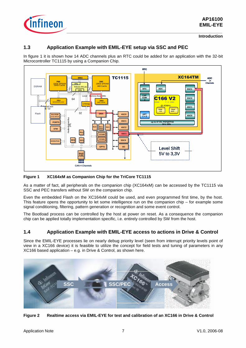
1.3 Application Example with EMIL-EYE setup via SSC and PEC
In figure 1 it is shown how 14 ADC channels plus an RTC could be added for an application with the 32-bit Microcontroller TC1115 by using a Companion Chip.
Figure 1 XC164xM as Companion Chip for the TriCore TC1115
As a matter of fact, all peripherals on the companion chip (XC164xM) can be accessed by the TC1115 via SSC and PEC transfers without SW on the companion chip.
Even the embedded Flash on the XC164xM could be used, and even programmed first time, by the host. This feature opens the opportunity to let some intelligence run on the companion chip – for example some signal conditioning, filtering, pattern generation or recognition and some event control.
The Bootload process can be controlled by the host at power on reset. As a consequence the companion chip can be applied totally implementation specific, i.e. entirely controlled by SW from the host.
1.4 Application Example with EMIL-EYE access to actions in Drive & Control
Since the EMIL-EYE processes lie on nearly debug priority level (seen from interrupt priority levels point of view in a XC166 device) it is feasible to utilize the concept for field tests and tuning of parameters in any XC166 based application – e.g. in Drive & Control, as shown here.
Figure 2 Realtime access via EMIL-EYE for test and calibration of an XC166 in Drive & Control
External bus16 / 32
TriCore (TC1.3)
LFI Bridge
DMI28KB SPRAM
4kB Cache
PMI32KB SPRAM16KB Cache
FPU
MMU
EBUSDRAM,BFLASH
DMU64KB SRAM
CPS
Fle x
ib le
Peri p
hera
lBus
(FP I
)
64
256128
32Boot ROM
16KB BROM
OCDS/JTAG
STM
PORTS
MultiCAN
4 Nodes
BCU SCU
PLL
GPTU
CCU60
CCU61
SMIF
BI0
MemCheck
MLI0
ASC0
ASC1
ASC2
SSC1
I2C
MLI1
CAN 4 Channels
DSRAM
Flash
������
SSC0
DMA
Local Memory Bus(LMB)
�������
Flash64 K
RAM6 K
@ 40MHz
THE Standard for 16- bit Solutions
up to 47 I/O, PG-TQFP-645V ± 10%
ADC
�������
Flash64 K
RAM6 K
@ 40MHz
THE Standard for 16- bit SolutionsTHE Standard for 16- bit Solutions
up to 47 I/O, PG-TQFP-645V ± 10%
ADC
up to 47 I/O, PG-TQFP-645V ± 10%
ADC
CAPCOM
2
GPT1 + 2
RTC
CAPCOM
2
CAPCOM
2
GPT1 + 2
RTC
GPT1 + 2
RTC SSC0
ASC0
SSC1
ASC1
SSC0SSC1
ASC0ASC0
SSC0
ASC1
ADC14
Channels
�����
RTC
Level Shift5V to 3,3V
External bus16 / 32
TriCore (TC1.3)
LFI Bridge
DMI28KB SPRAM
4kB Cache
PMI32KB SPRAM16KB Cache
FPU
MMU
EBUSDRAM,BFLASH
DMU64KB SRAM
CPS
Fle x
ib le
Peri p
hera
lBus
(FP I
)
64
256128
32Boot ROM
16KB BROM
OCDS/JTAG
STM
PORTS
MultiCAN
4 Nodes
BCU SCU
PLL
GPTU
CCU60
CCU61
SMIF
BI0
MemCheck
MLI0
ASC0
ASC1
ASC2
SSC1
I2C
MLI1
CAN 4 Channels
DSRAM
Flash
������
SSC0SSC0
DMA
Local Memory Bus(LMB)
�������
Flash64 K
RAM6 K
@ 40MHz
THE Standard for 16- bit Solutions
up to 47 I/O, PG-TQFP-645V ± 10%
ADC
�������
Flash64 K
RAM6 K
@ 40MHz
THE Standard for 16- bit SolutionsTHE Standard for 16- bit Solutions
up to 47 I/O, PG-TQFP-645V ± 10%
ADC
up to 47 I/O, PG-TQFP-645V ± 10%
ADC
CAPCOM
2
GPT1 + 2
RTC
CAPCOM
2
CAPCOM
2
GPT1 + 2
RTC
GPT1 + 2
RTC SSC0
ASC0
SSC1
ASC1
SSC0SSC1
ASC0ASC0
SSC0
ASC1
ADC14
Channels
�����
RTC
�������
Flash64 K
RAM6 K
@ 40MHz
THE Standard for 16- bit Solutions
up to 47 I/O, PG-TQFP-645V ± 10%
ADC
�������
Flash64 K
RAM6 K
@ 40MHz
THE Standard for 16- bit SolutionsTHE Standard for 16- bit Solutions
up to 47 I/O, PG-TQFP-645V ± 10%
ADC
up to 47 I/O, PG-TQFP-645V ± 10%
ADC
CAPCOM
2
GPT1 + 2
RTC
CAPCOM
2
CAPCOM
2
GPT1 + 2
RTC
GPT1 + 2
RTC
CAPCOM
2
GPT1 + 2
RTC
CAPCOM
2
CAPCOM
2
GPT1 + 2
RTC
GPT1 + 2
RTC SSC0
ASC0
SSC1
ASC1
SSC0SSC1
ASC0ASC0
SSC0
ASC1
SSC0
ASC0
SSC1
ASC1
SSC0SSC1
ASC0ASC0
SSC0
ASC1
ADC14
Channels
�����
RTC
Level Shift5V to 3,3VLevel Shift5V to 3,3V
SSC SSC/PEC AccessSSC SSC/PEC Access

AP16100 EMIL-EYE
EMIL-EYE Basics
Application Note 8 V1.0, 2006-08
2 EMIL-EYE Basics
2.1 Properties
� Up to 10 Mbit/s SSC (SPI) protocol.
� Core independent primitives, just DATA transfers – no instructions.
� PEC Service at the Slave side. (I.e. no code execution! Code is optional.)
� Master-Slave hierarchy. The Master supervises the Slave via SSC and PEC.
� Simple, generic protocol with Frame Cells sent by a Master.
� No Control Lines needed!
� Generic Boot-up of Slave (Companion Chip) by the Master (Host).
� Each 32-bit Frame Cell consists of two 16-bit words - “whereto” and “what”:
2.2 Protocol
Figure 3 The EMIL-EYE protocol
SSC PEC
Host: Companion:
Ports
ADC
RTC
ASCSSC
CC6
CCU
RAM
GPT
{Resources:
SSC Protocol:
ADDR DATA
Action
AnyMicrocontroller
withSSC(SPI)
Host Command: ADDR DATA
Companion Response: Action
Frame Cell:
(2 x 16 bits
3,2 us @ 10 Mbit/s)
SSC PEC
Host: Companion:
Ports
ADC
RTC
ASCSSC
CC6
CCU
RAM
GPT
{Resources:
SSC Protocol:
ADDR DATA
Action
AnyMicrocontroller
withSSC(SPI)
Host Command: ADDR DATA
Companion Response: Action
Frame Cell:
(2 x 16 bits
3,2 us @ 10 Mbit/s)
AP16100 EMIL-EYE
EMIL-EYE Basics
Application Note 9 V1.0, 2006-08
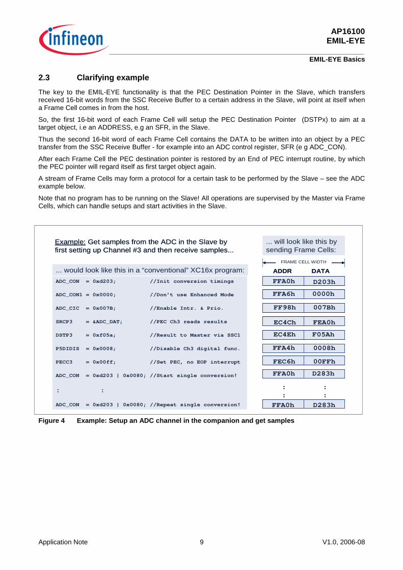
2.3 Clarifying example
The key to the EMIL-EYE functionality is that the PEC Destination Pointer in the Slave, which transfers received 16-bit words from the SSC Receive Buffer to a certain address in the Slave, will point at itself when a Frame Cell comes in from the host.
So, the first 16-bit word of each Frame Cell will setup the PEC Destination Pointer (DSTPx) to aim at a target object, i.e an ADDRESS, e.g an SFR, in the Slave.
Thus the second 16-bit word of each Frame Cell contains the DATA to be written into an object by a PEC transfer from the SSC Receive Buffer - for example into an ADC control register, SFR (e g ADC_CON).
After each Frame Cell the PEC destination pointer is restored by an End of PEC interrupt routine, by which the PEC pointer will regard itself as first target object again.
A stream of Frame Cells may form a protocol for a certain task to be performed by the Slave – see the ADC example below.
Note that no program has to be running on the Slave! All operations are supervised by the Master via Frame Cells, which can handle setups and start activities in the Slave.
Figure 4 Example: Setup an ADC channel in the companion and get samples
D283h
D283h
00FFh
0008h
Example: Get samples from the ADC in the Slave byfirst setting up Channel #3 and then receive samples...
ADC_CON = 0xd203; //Init conversion timings
ADC_CON1 = 0x0000; //Don’t use Enhanced Mode
ADC_CIC = 0x007B; //Enable Intr. & Prio.
SRCP3 = &ADC_DAT; //PEC Ch3 reads results
DSTP3 = 0xf05a; //Result to Master via SSC1
P5DIDIS = 0x0008; //Disable Ch3 digital func.
PECC3 = 0x00ff; //Set PEC, no EOP interrupt
ADC_CON = 0xd203 | 0x0080; //Start single conversion!
: :
ADC_CON = 0xd203 | 0x0080; //Repeat single conversion! FFA0h
FFA0h
FEC6h
FFA4h
EC4Eh F05Ah
EC4Ch FEA0h
007Bh FF98h
0000h FFA6h
D203h FFA0h
::
::
FRAME CELL WIDTH
ADDR DATA... would look like this in a “conventional” XC16x program:
... will look like this by sending Frame Cells:
D283h
D283h
00FFh
0008h
Example: Get samples from the ADC in the Slave byfirst setting up Channel #3 and then receive samples...
ADC_CON = 0xd203; //Init conversion timings
ADC_CON1 = 0x0000; //Don’t use Enhanced Mode
ADC_CIC = 0x007B; //Enable Intr. & Prio.
SRCP3 = &ADC_DAT; //PEC Ch3 reads results
DSTP3 = 0xf05a; //Result to Master via SSC1
P5DIDIS = 0x0008; //Disable Ch3 digital func.
PECC3 = 0x00ff; //Set PEC, no EOP interrupt
ADC_CON = 0xd203 | 0x0080; //Start single conversion!
: :
ADC_CON = 0xd203 | 0x0080; //Repeat single conversion! FFA0h
FFA0h
FEC6h
FFA4h
EC4Eh F05Ah
EC4Ch FEA0h
007Bh FF98h
0000h FFA6h
D203h FFA0h
::
::
FRAME CELL WIDTHFRAME CELL WIDTH
ADDR DATA... would look like this in a “conventional” XC16x program:
... will look like this by sending Frame Cells:
AP16100 EMIL-EYE
EMIL-EYE Basics
Application Note 10 V1.0, 2006-08
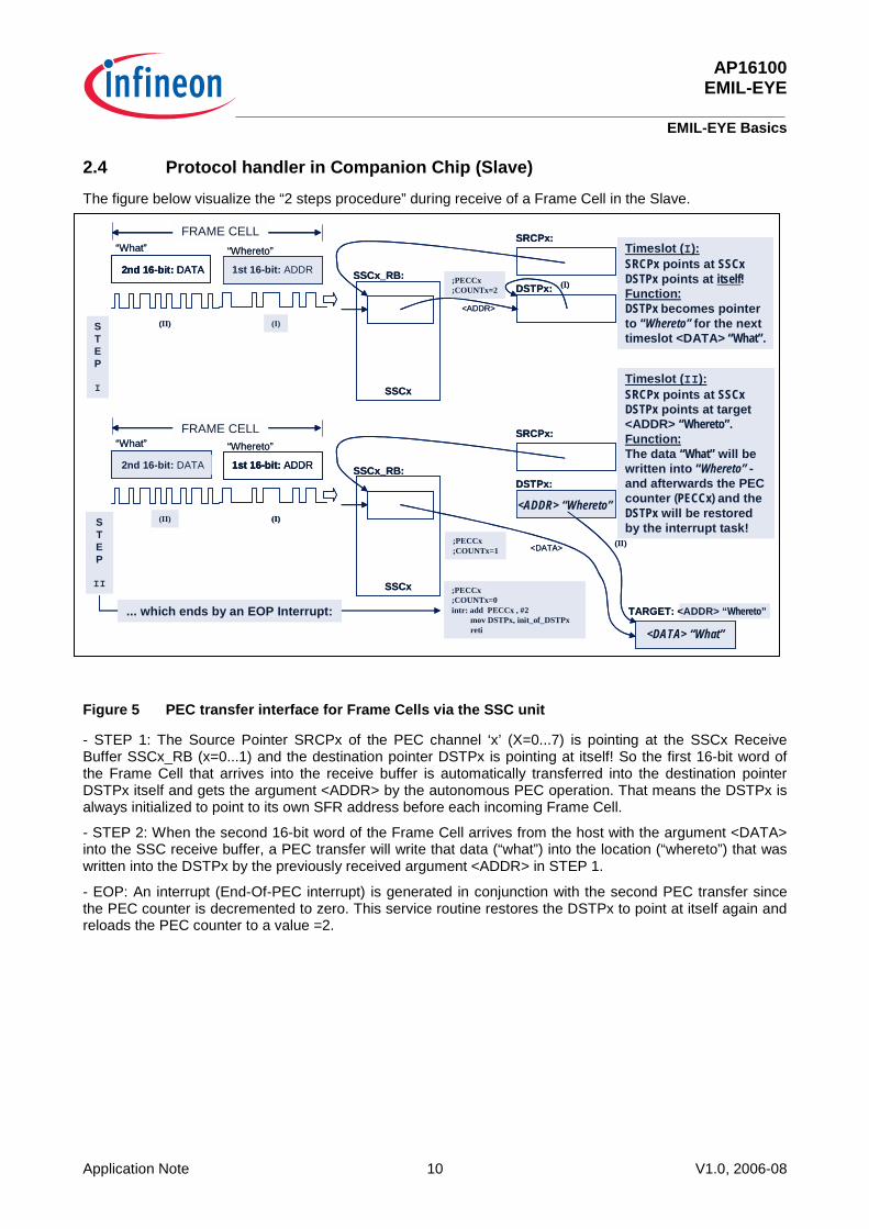
2.4 Protocol handler in Companion Chip (Slave)
The figure below visualize the “2 steps procedure” during receive of a Frame Cell in the Slave.
Figure 5 PEC transfer interface for Frame Cells via the SSC unit
- STEP 1: The Source Pointer SRCPx of the PEC channel ‘x’ (X=0...7) is pointing at the SSCx Receive Buffer SSCx_RB (x=0...1) and the destination pointer DSTPx is pointing at itself! So the first 16-bit word of the Frame Cell that arrives into the receive buffer is automatically transferred into the destination pointer DSTPx itself and gets the argument <ADDR> by the autonomous PEC operation. That means the DSTPx is always initialized to point to its own SFR address before each incoming Frame Cell.
- STEP 2: When the second 16-bit word of the Frame Cell arrives from the host with the argument <DATA> into the SSC receive buffer, a PEC transfer will write that data (“what”) into the location (“whereto”) that was written into the DSTPx by the previously received argument <ADDR> in STEP 1.
- EOP: An interrupt (End-Of-PEC interrupt) is generated in conjunction with the second PEC transfer since the PEC counter is decremented to zero. This service routine restores the DSTPx to point at itself again and reloads the PEC counter to a value =2.
TARGET: <ADDR> “Whereto”
;PECCx;COUNTx=2 DSTPx:
SRCPx:
SSCx_RB:
<ADDR>
1st 16-bit: ADDR2nd 16-bit: DATA(I)
(I)(II)
FRAME CELL
“Whereto”“What”
;PECCx;COUNTx=0intr: add PECCx , #2
mov DSTPx, init_of_DSTPxreti
;PECCx;COUNTx=1
DSTPx:
SRCPx:
SSCx_RB:
<DATA>
1st 16-bit: ADDR2nd 16-bit: DATA
(II)
(I)(II)
“Whereto”“What”
Timeslot (I):SRCPx points at SSCxDSTPx points at itself!Function:DSTPx becomes pointerto “Whereto” for the nexttimeslot <DATA> “What”.
Timeslot (II):SRCPx points at SSCxDSTPx points at target <ADDR> “Whereto”.Function:The data “What” will bewritten into “Whereto” -and afterwards the PECcounter (PECCx) and theDSTPx will be restoredby the interrupt task!
<DATA> “What”
SSCx
SSCx
STEP
I
STEP
II
<ADDR> “Whereto”
FRAME CELL
... which ends by an EOP Interrupt: TARGET: <ADDR> “Whereto”
;PECCx;COUNTx=2 DSTPx:
SRCPx:
SSCx_RB:
<ADDR>
1st 16-bit: ADDR1st 16-bit: ADDR2nd 16-bit: DATA2nd 16-bit: DATA(I)
(I)(II)
FRAME CELLFRAME CELL
“Whereto”“What”
;PECCx;COUNTx=0intr: add PECCx , #2
mov DSTPx, init_of_DSTPxreti
;PECCx;COUNTx=1
DSTPx:
SRCPx:
SSCx_RB:
<DATA>
1st 16-bit: ADDR1st 16-bit: ADDR2nd 16-bit: DATA2nd 16-bit: DATA
(II)
(I)(II)
“Whereto”“What”
Timeslot (I):SRCPx points at SSCxDSTPx points at itself!Function:DSTPx becomes pointerto “Whereto” for the nexttimeslot <DATA> “What”.
Timeslot (II):SRCPx points at SSCxDSTPx points at target <ADDR> “Whereto”.Function:The data “What” will bewritten into “Whereto” -and afterwards the PECcounter (PECCx) and theDSTPx will be restoredby the interrupt task!
<DATA> “What”
SSCx
SSCx
STEP
I
STEP
II
<ADDR> “Whereto”
FRAME CELLFRAME CELL
... which ends by an EOP Interrupt:
AP16100 EMIL-EYE
EMIL-EYE Basics
Application Note 11 V1.0, 2006-08
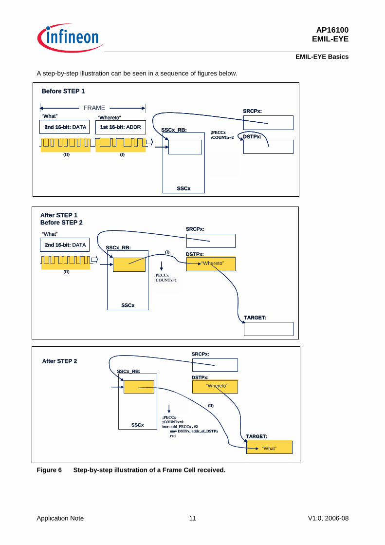
A step-by-step illustration can be seen in a sequence of figures below.
Figure 6 Step-by-step illustration of a Frame Cell received.
1st 16-bit: ADDR
;PECCx;COUNTx=1
;PECCx;COUNTx=2 DSTPx:
SRCPx:
SSCx_RB:2nd 16-bit: DATA
(I)(II)
FRAME
“Whereto”“What”
SSCx
Before STEP 1
1st 16-bit: ADDR
;PECCx;COUNTx=1
;PECCx;COUNTx=2 DSTPx:
SRCPx:
SSCx_RB:2nd 16-bit: DATA
(I)(II)
FRAME
“Whereto”“What”
SSCx
1st 16-bit: ADDR1st 16-bit: ADDR
;PECCx;COUNTx=1
;PECCx;COUNTx=2 DSTPx:
SRCPx:
SSCx_RB:2nd 16-bit: DATA2nd 16-bit: DATA
(I)(II)
FRAMEFRAME
“Whereto”“What”
SSCx
Before STEP 1
2nd 16-bit: DATA
(II)
“What”
;PECCx;COUNTx=1
DSTPx:
TARGET:
SRCPx:
SSCx_RB:
SSCx
;PECCx;COUNTx=1
“Whereto”
(I)
After STEP 1Before STEP 2
2nd 16-bit: DATA2nd 16-bit: DATA
(II)
“What”
;PECCx;COUNTx=1
DSTPx:
TARGET:TARGET:
SRCPx:
SSCx_RB:
SSCx
;PECCx;COUNTx=1
“Whereto”
(I)
After STEP 1Before STEP 2
(II)
“What”
;PECCx;COUNTx=1
DSTPx:
TARGET:
SRCPx:
SSCx_RB:
SSCx
“Whereto”
;PECCx;COUNTx=0intr: add PECCx , #2
mov DSTPx, addr_of_DSTPxreti
After STEP 2
(II)
“What”
;PECCx;COUNTx=1
DSTPx:
TARGET:TARGET:
SRCPx:
SSCx_RB:
SSCx
“Whereto”
;PECCx;COUNTx=0intr: add PECCx , #2
mov DSTPx, addr_of_DSTPxreti
After STEP 2
AP16100 EMIL-EYE
EMIL-EYE Download / Upload protocols
Application Note 12 V1.0, 2006-08
3 EMIL-EYE Download / Upload protocols By regarding Frame Cells as a puzzle of pieces makes it possible to build different protocols by the host (Master) to manipulate data, operations and even program code in the companion chip (Slave). The smallest “piece” is the DOWNL template which is one Frame Cell wide (= 2 x 16-bit words as previously described).
3.1 Download – The DOWNL template
The host microcontroller or processor (Master) has to send two consecutive 16-bit arguments over the SSC (SPI) line, in order to perform a write operation of a data “what” at a location “whereto” on the companion chip. Since the SSCx SFR registers reside in Segment 00, both PEC segment pointers, DSTSEGx and SRCSEGx, have to be zero (=00), which they are by default after power on reset though.
Master: Downl (template) void downl(uword *whereto, uword what); { SSCx_vSendData(whereto); //x=0 or 1 for SSC0 resp SSC1 SSCx_vSendData(what); }
To address another segment than 00 requires the use of a second PEC channel (‘z’) and an intersegment move of the data “what” via an intermediate buffer.
If there is an intention to download more than one data to such a segment (zz<>00), it’s advisable to set up a second PEC channel first, dedicated for the internal transfers. You may “borrow” the SSCx Transmit Interrupt PEC Channel for that purpose, by redirecting the according PEC pointers and set the PEC counter value accordingly:
downl(&SRCPy,&buffer); //Point at intermediate data buffer downl(&DSTPy,whereto); //Point at “whereto” location downl(&DSTSEGy,0x00zz);//in segment ‘zz’. downl(&PECCy,0x00ff); //No PEC counter decount, nor EOP intr! downl(&buffer,what); // OK – now send a data to the buffer! downl(&SSCx_TIC,0x79|0x80); //Let it be moved to “whereto” in segment ‘zz’ by PEC transfer!
By setting the PECCy for incrementing DSTPy mode, a sequence of data may be written into an array in the segment ‘zz’ by repeating the last to downl-lines.
3.2 Upload – The UPL template
An Upload protocol can be built by 3 Frame Cells to transmit a 16-bit data from a location “wherefrom” in the companion chip (slave) to the host (master). A source pointer SRCPy for the SSCx Transmit Buffer has to be set, a PEC Counter (for one transmission) has to be set and the operation is stimulated by the host when it sends a Frame Cell that sets the Interrupt Request Flag in the SFR SSCx_TIC!
(The DSTPy and DSTSEGy pointers are assumed to be set already by initialization SW at power on reset.)
Master: Upload (setup template) void upl(uword *wherefrom) { downl(&SRCPy,wherefrom); downl(&PECCy,0x0001); // PEC Channel #y for 1 Transmit downl(&SSCx_TIC,0x79|0x80); // Start transmit via PEC by // setting the Interrupt flag! }
AP16100 EMIL-EYE
EMIL-EYE Initialization
Application Note 13 V1.0, 2006-08
Master: Next Upload downl(&PECCy,0x0001); downl(&SSCx_TIC,0x79 | 0x80);
3.3 Block Upload – The BLKUPL template
A command from the host may be a complex task for the companion chip, for example to upload an entire data block from the companion chip to the host – as follows:
Block Upload a BLKLEN number of words from location “wherefrom” to the host: downl(&SRCPy,wherefrom); downl(&DSTPx,&SSCx_TB); downl(&PECCx,0x0400|BLKLEN;//Inc SRC along the whole length downl(&SSCx_TIC,0x79 | 0x80); //Start the BLKUPL process!
From this moment the host can “put its arms across” and await all the data transmitted. The number of transmissions is determined by the block length BLKLEN – and when the last word has been transmitted and the PEC counter has decremented to zero, an EOP interrupt will clear the SSCx_TIC control register automatically.
4 EMIL-EYE Initialization
4.1 EOP Interrupt handling
Since all actions on the companion chip are based on PEC operations, there has to be a set of End-Of-PEC (EOP) interrupt service routines that ends each PEC cycle that has been used.
Each Frame Cell that is received by the Slave SSCx unit consumes a PEC cycle of two PEC transfers of 16-bit data – and requires a restore of the PEC SFR registers in front of each next Frame Cell sent to the SSCx unit in the companion chip (slave).
The upload procedure (UPL), described above, requires an EOP interrupt handling as well – in order to clear the SSCx_TIC interrupt control register.
The context switching has been avoided in the templates recommended below. In order to make each interrupt task as “discrete” as possible in the sense “do not impact on other execution onboard, if such is programmed and running”, Neither are any PUSH, POP invoked nor system control registers, like the PSW, manipulated.
4.2 The Frame Cell EOP Interrupt template
In the following EOP template example the PEC Channel #0 is shown how to be used:
_SSCx_viRx PROC TASK SSCx_Rx_TASK INTNO SSCx_Rx_INUM = 052h
add PECCx,#2H ;Restore counter to the value=2. movw DSTPx , AnyFreeSFR ;Use any free, unlikely used 8-bit ;addressable register to carry the ;restore value for DSTPx (=#DSTPx)!
;So, no register bank is disturbed!
RETI
_SSCx_viRx ENDP
AP16100 EMIL-EYE
EMIL-EYE Implementation Guide
Application Note 14 V1.0, 2006-08
4.3 The SSCx Transmit Interrupt template
PEC transfers onboard as well as for transmission of data back to the host is based on the SSCx_TIC PEC Channel and corresponding EOP interrupt shown below:
_SSCx_viTx PROC TASK SSCx_Tx_TASK_ INTNO SSCx_Tx_INUM_ = 051h
AND SSCx_TIC , ZEROS ;Disable this channel after use!
RETI
_SSCx_viTx ENDP
4.4 Companion Chip (Slave) Setup Template
The most essential initializations that have to be performed after power on reset and Boot Loading are shown here – as a template:
SSC1_vInit(void) ;
/*** Default init: *****/
DSTPx = (uword)(&DSTPx);
SRCPx = (uword)(&SSCx_RB);
PECCx = 0x0002;
AnyFreeSFR = (uword)(&DSTPx); //Used in the SSCx_TIC EOP interrupt //routine to restore the DSTPx value
5 EMIL-EYE Implementation Guide This session will give some hints about some different ways to set up an EMIL-EYE implementation for a companion chip.
First alternative will show an easy way by using any XC166 microcontroller with a preprogrammed eFlash. That solution also shows basically how the EMIL-EYE could be implemented as a Test/Calibration add-on feature for any XC166 single chip application, where it is not utilized as a companion chip. You will need the appropriate development tool set for the XC166 family to get the embedded Flash programmed.
Second alternative will show implementations that require some kind of Bootload procedure, where maybe the embedded eFlash is not necessarily used at all. In this case the XC166 header files for SFR declarations will do plus XC166 Users Manuals.
5.1 Companion Chip with EMIL-EYE implementation on the XC166 eFlash
Let’s assume there is an appropriate START.ASM existing (e.g. easily generated by the SW configuration tools on the DAvE CD), according to the HW configuration, including XTAL and CPU clock settings that will be used in a specific application. There might also exist other application specific SW intended to be linked.
The following C file has to be linked as well to invoke the EMIL-EYE add-on features. It’s assumed that highest priority level (ILVL) = 15 and highest group level (GLVL) =3 will be used.
AP16100 EMIL-EYE
EMIL-EYE Implementation Guide
Application Note 15 V1.0, 2006-08
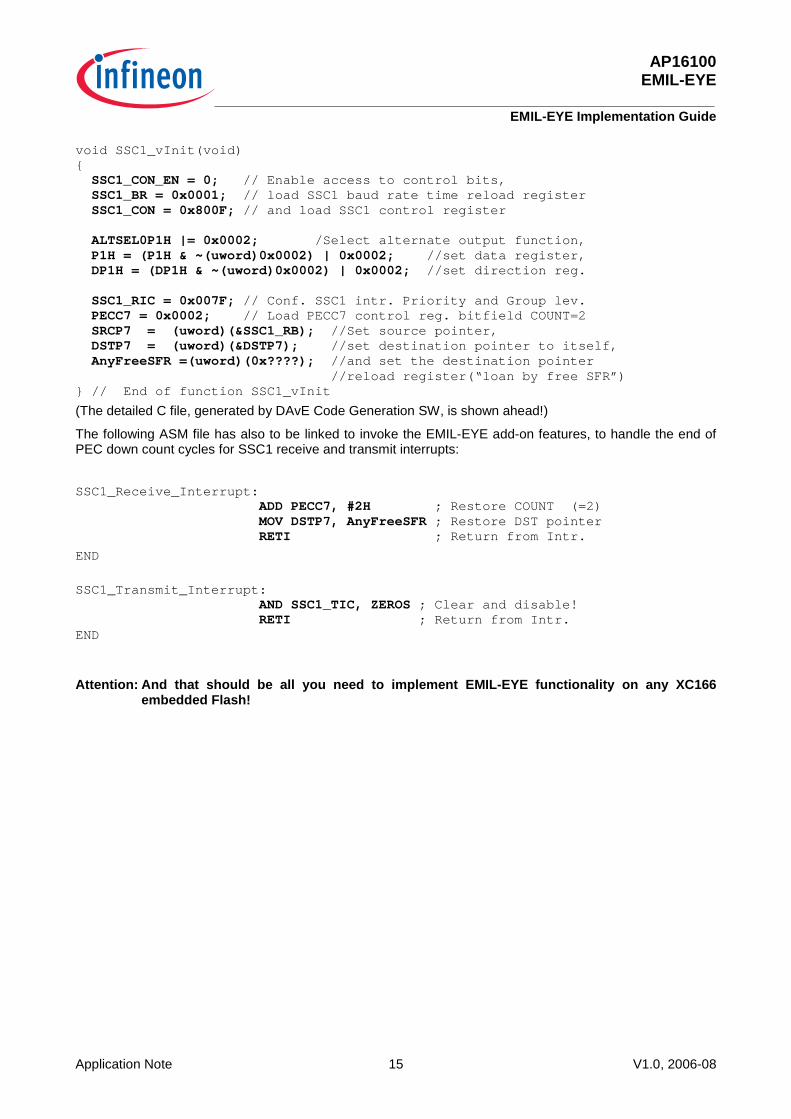
void SSC1_vInit(void) { SSC1_CON_EN = 0; // Enable access to control bits, SSC1_BR = 0x0001; // load SSC1 baud rate time reload register SSC1_CON = 0x800F; // and load SSC1 control register ALTSEL0P1H |= 0x0002; /Select alternate output function, P1H = (P1H & ~(uword)0x0002) | 0x0002; //set data register, DP1H = (DP1H & ~(uword)0x0002) | 0x0002; //set direction reg. SSC1_RIC = 0x007F; // Conf. SSC1 intr. Priority and Group lev. PECC7 = 0x0002; // Load PECC7 control reg. bitfield COUNT=2 SRCP7 = (uword)(&SSC1_RB); //Set source pointer, DSTP7 = (uword)(&DSTP7); //set destination pointer to itself, AnyFreeSFR =(uword)(0x????); //and set the destination pointer //reload register(“loan by free SFR”) } // End of function SSC1_vInit
(The detailed C file, generated by DAvE Code Generation SW, is shown ahead!)
The following ASM file has also to be linked to invoke the EMIL-EYE add-on features, to handle the end of PEC down count cycles for SSC1 receive and transmit interrupts:
SSC1_Receive_Interrupt: ADD PECC7, #2H ; Restore COUNT (=2) MOV DSTP7, AnyFreeSFR ; Restore DST pointer RETI ; Return from Intr.
END
SSC1_Transmit_Interrupt: AND SSC1_TIC, ZEROS ; Clear and disable! RETI ; Return from Intr. END
Attention: And that should be all you need to implement EMIL-EYE functionality on any XC166 embedded Flash!
AP16100 EMIL-EYE
EMIL-EYE Implementation Guide
Application Note 16 V1.0, 2006-08
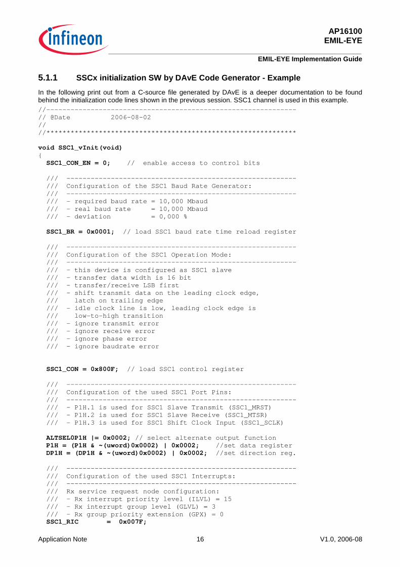
5.1.1 SSCx initialization SW by DAvE Code Generator - Example
In the following print out from a C-source file generated by DAvE is a deeper documentation to be found behind the initialization code lines shown in the previous session. SSC1 channel is used in this example. //-------------------------------------------------------------- // @Date 2006-08-02 // //************************************************************** void SSC1_vInit(void) { SSC1_CON_EN = 0; // enable access to control bits /// --------------------------------------------------------- /// Configuration of the SSC1 Baud Rate Generator: /// --------------------------------------------------------- /// - required baud rate = 10,000 Mbaud /// - real baud rate = 10,000 Mbaud /// - deviation = 0,000 % SSC1_BR = 0x0001; // load SSC1 baud rate time reload register /// --------------------------------------------------------- /// Configuration of the SSC1 Operation Mode: /// --------------------------------------------------------- /// - this device is configured as SSC1 slave /// - transfer data width is 16 bit /// - transfer/receive LSB first /// - shift transmit data on the leading clock edge, /// latch on trailing edge /// - idle clock line is low, leading clock edge is /// low-to-high transition /// - ignore transmit error /// - ignore receive error /// - ignore phase error /// - ignore baudrate error SSC1_CON = 0x800F; // load SSC1 control register /// --------------------------------------------------------- /// Configuration of the used SSC1 Port Pins: /// --------------------------------------------------------- /// - P1H.1 is used for SSC1 Slave Transmit (SSC1_MRST) /// - P1H.2 is used for SSC1 Slave Receive (SSC1_MTSR) /// - P1H.3 is used for SSC1 Shift Clock Input (SSC1_SCLK) ALTSEL0P1H |= 0x0002; // select alternate output function P1H = (P1H & ~(uword)0x0002) | 0x0002; //set data register DP1H = (DP1H & ~(uword)0x0002) | 0x0002; //set direction reg. /// --------------------------------------------------------- /// Configuration of the used SSC1 Interrupts: /// --------------------------------------------------------- /// Rx service request node configuration: /// - Rx interrupt priority level (ILVL) = 15 /// - Rx interrupt group level (GLVL) = 3 /// - Rx group priority extension (GPX) = 0 SSC1_RIC = 0x007F;
AP16100 EMIL-EYE
EMIL-EYE Implementation Guide
Application Note 17 V1.0, 2006-08
/// Use PEC channel 7 for SSC1 Rx INT: /// - decrement counter /// - pointers are not modified /// - transfer a word /// - service End of PEC intr. by EOP intr. Node is disabled PECC7 = 0x0002; // load PECC7 control register SRCP7 = (uword)(&SSC1_RB); //set source pointer DSTP7 = (uword)(&DSTP7); //set destination pointer to itself AnyFreeSFR =(uword)(&DSTP7); //set destination pointer //reload register(“loan by free SFR”) } // End of function SSC1_vInit
5.2 Companion Chip without EMIL-EYE implementation on the XC166 eFlash
In principal the same programming of the companion chip has to be done after Power on Reset when the eFlash is NOT intended to be used – but the PSRAM instead. That means, the initialization code for the SSCx unit has to be downloaded into the PSRAM – and so is also required for the EOP Interrupt service routines (looking the same as when eFlash is used – but the interrupt Vector Segment Pointer will refer to the root address of the PSRAM instead, i.e. at segment 0Eh!
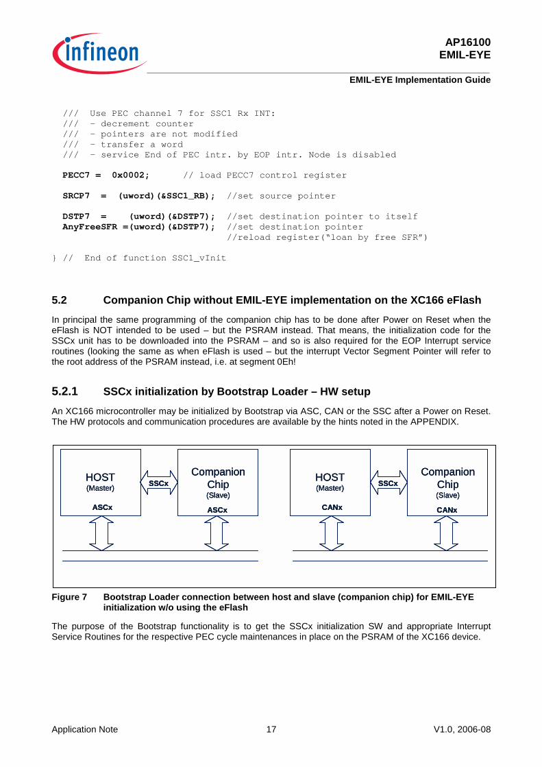
5.2.1 SSCx initialization by Bootstrap Loader – HW setup
An XC166 microcontroller may be initialized by Bootstrap via ASC, CAN or the SSC after a Power on Reset. The HW protocols and communication procedures are available by the hints noted in the APPENDIX.
Figure 7 Bootstrap Loader connection between host and slave (companion chip) for EMIL-EYE initialization w/o using the eFlash
The purpose of the Bootstrap functionality is to get the SSCx initialization SW and appropriate Interrupt Service Routines for the respective PEC cycle maintenances in place on the PSRAM of the XC166 device.
HOST(Master)
CompanionChip(Slave)
ASCx ASCx
SSCxHOST(Master)
CompanionChip(Slave)
CANx CANx
SSCxHOST(Master)
CompanionChip(Slave)
ASCx ASCx
SSCxHOST(Master)
CompanionChip(Slave)
ASCx ASCx
SSCxHOST(Master)
CompanionChip(Slave)
CANx CANx
SSCxHOST(Master)
CompanionChip(Slave)
CANx CANx
SSCx
AP16100 EMIL-EYE
EMIL-EYE Implementation Guide
Application Note 18 V1.0, 2006-08
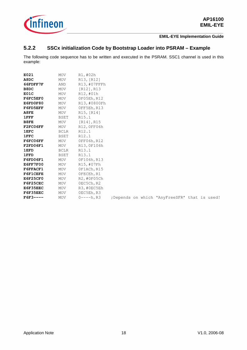
5.2.2 SSCx initialization Code by Bootstrap Loader into PSRAM – Example
The following code sequence has to be written and executed in the PSRAM. SSC1 channel is used in this example:
E021 MOV R1,#02h A8DC MOV R13,[R12] 66FDFF7F AND R13,#07FFFh B8DC MOV [R12],R13 E01C MOV R12,#01h F6FC5EF0 MOV 0F05Eh,R12 E6FD0F80 MOV R13,#0800Fh F6FD5EFF MOV 0FF5Eh,R13 A8FE MOV R15,[R14] 1FFF BSET R15.1 B8FE MOV [R14],R15 F2FC06FF MOV R12,0FF06h 1EFC BCLR R12.1 1FFC BSET R12.1 F6FC06FF MOV 0FF06h,R12 F2FD06F1 MOV R13,0F106h 1EFD BCLR R13.1 1FFD BSET R13.1 F6FD06F1 MOV 0F106h,R13 E6FF7F00 MOV R15,#07Fh F6FFACF1 MOV 0F1ACh,R15 F6F1CEFE MOV 0FECEh,R1 E6F25CF0 MOV R2,#0F05Ch F6F25CEC MOV 0EC5Ch,R2 E6F35EEC MOV R3,#0EC5Eh F6F35EEC MOV 0EC5Eh,R3 F6F3---- MOV 0----h,R3 ;Depends on which “AnyFreeSFR” that is used!

AP16100 EMIL-EYE
Appendix
Application Note 19 V1.0, 2006-08
6 Appendix The following hints show different approaches to Bootstrap the EMIL-EYE initialization at Power on Reset when the eFlash is not preprogrammed on the XC166 microcontroller...
6.1 XC166 family ASC Bootstrap Loader
In the chapter “The Bootstrap Loader” in any XC166’s “Users Manuals System Units” the detailed description of the Bootstrap functionality is to be found. Using the ASC communication for this purpose will “cost” one ASC resource on both the host as well as on the companion chip – but is en easy, straight forward alternative solution though.
6.2 XC166 family CAN Bootstrap Loader – AP16092
If the application, where the XC166 as companion chip is going to be implemented, uses CAN anyway, it could be recommendable to utilize CAN communication for the initialization of the EMIL-EYE.
There is an Application Note available on the Infineon Internet website:
http://www.infineon.com/upload/Document/AIM/Microcontroller/16bit/ap1609210_CAN_Bootloader.pdf
This PDF file contains the procedures for the HW setup and SW templates in detail.
The code restored in PSRAM may be the final application code. It may also contain a code sequence to change the system configuration and enable the bus interface to store the received data into external memory. For example, the flash driver may be loaded and used for the on-chip flash programming via CAN BSL. For details please refer to the application note AP16048 “XC166 Flash-on-the-Fly”:
http://www.infineon.com/upload/Document/cmc_upload/documents/097/556/AP1604811_flash_on_the_fly.pdf
6.3 XC166 family SSC Bootstrap Loader
This alternative wouldn’t impact on other serial communication unit resources of neither the host nor the companion chip as the CAN or the ASC alternatives would do.
The SSC Bootloader alternative has to be defined.

AP16100 EMIL-EYE
Last words…
Application Note 20 V1.0, 2006-08
7 Last words… Attention: All documents like datasheets, user’s manuals or addendums for the selected device
should be crosschecked in all aspects regarding new functions or deviations to former versions and the latest documents should always be used.
The latest XC166 family related documents can be found by the following link:
http://www.infineon.com/xc166
In case for any reason this link does not work you can find such information by the links:
Infineon home page: http://www.infineon.com
Infineon microcontroller home page: http://www.infineon.com/microcontrollers

AP16100 EMIL-EYE
Last words…
Application Note 21 V1.0, 2006-08

http:/ /www.inf ineon.com
Published by Infineon Technologies AG